US8842935B2 - Image capturing apparatus with image compensation and method thereof - Google Patents
Image capturing apparatus with image compensation and method thereof Download PDFInfo
- Publication number
- US8842935B2 US8842935B2 US11/525,055 US52505506A US8842935B2 US 8842935 B2 US8842935 B2 US 8842935B2 US 52505506 A US52505506 A US 52505506A US 8842935 B2 US8842935 B2 US 8842935B2
- Authority
- US
- United States
- Prior art keywords
- image
- tilt
- capturer
- compensation
- region
- Prior art date
- Legal status (The legal status is an assumption and is not a legal conclusion. Google has not performed a legal analysis and makes no representation as to the accuracy of the status listed.)
- Expired - Fee Related, expires
Links
Images


Classifications
-
- H—ELECTRICITY
- H04—ELECTRIC COMMUNICATION TECHNIQUE
- H04N—PICTORIAL COMMUNICATION, e.g. TELEVISION
- H04N7/00—Television systems
- H04N7/14—Systems for two-way working
- H04N7/141—Systems for two-way working between two video terminals, e.g. videophone
- H04N7/142—Constructional details of the terminal equipment, e.g. arrangements of the camera and the display
-
- H—ELECTRICITY
- H04—ELECTRIC COMMUNICATION TECHNIQUE
- H04N—PICTORIAL COMMUNICATION, e.g. TELEVISION
- H04N23/00—Cameras or camera modules comprising electronic image sensors; Control thereof
- H04N23/60—Control of cameras or camera modules
- H04N23/61—Control of cameras or camera modules based on recognised objects
-
- H—ELECTRICITY
- H04—ELECTRIC COMMUNICATION TECHNIQUE
- H04N—PICTORIAL COMMUNICATION, e.g. TELEVISION
- H04N23/00—Cameras or camera modules comprising electronic image sensors; Control thereof
- H04N23/60—Control of cameras or camera modules
- H04N23/63—Control of cameras or camera modules by using electronic viewfinders
-
- H04N5/23293—
-
- H—ELECTRICITY
- H04—ELECTRIC COMMUNICATION TECHNIQUE
- H04N—PICTORIAL COMMUNICATION, e.g. TELEVISION
- H04N5/00—Details of television systems
- H04N5/222—Studio circuitry; Studio devices; Studio equipment
- H04N5/262—Studio circuits, e.g. for mixing, switching-over, change of character of image, other special effects ; Cameras specially adapted for the electronic generation of special effects
- H04N5/2628—Alteration of picture size, shape, position or orientation, e.g. zooming, rotation, rolling, perspective, translation
-
- H—ELECTRICITY
- H04—ELECTRIC COMMUNICATION TECHNIQUE
- H04N—PICTORIAL COMMUNICATION, e.g. TELEVISION
- H04N7/00—Television systems
- H04N7/14—Systems for two-way working
- H04N7/141—Systems for two-way working between two video terminals, e.g. videophone
- H04N7/142—Constructional details of the terminal equipment, e.g. arrangements of the camera and the display
- H04N2007/145—Handheld terminals
Definitions
- the present invention relates to an image capturing apparatus with image compensation and a method thereof, and more particularly to an image capturing apparatus with image compensation and a method thereof, which can perform compensation of a user's facial image that is distorted in accordance with the position of a camera relative to an imaged object.
- An IMT-2000 service which is the recently appearing next-generation mobile communication service, goes a step further to provide a video photography function between users of mobile communication devices having provided with cameras.
- a user maintains a posture looking down toward the mobile communication device in hand because video telephony generally requires that the user continuously gaze at a communication partner's facial image displayed on the screen of the mobile communication device for several to tens of minutes. That is, the camera attached to the mobile communication device is mostly located below the user's face to capture the face of the user.
- the image of the user's face in three-dimensions is distorted in such a manner that user's chin appears to be larger that it actually is and user's forehead appears to be more narrow than it actually is. This phenomenon is called perspective.
- This distorted facial image is generally unnatural to users and may cause psychological rejection, which may delay the widespread use of video photography devices.
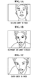
- a mobile communication device is located below a user's face as illustrated in FIG. 1A , in front of the user's face as illustrated in FIG. 1B , or over (i.e., above) the user's face as illustrated in FIG. 1C , user's facial images captured by the mobile communication device may differ depending on the image capturing angles.
- the user maintains a posture looking down on the mobile communication device i.e., if the user's facial image is captured by the mobile communication device that is positioned below the user's face, the user's chin appears to be larger and the user's forehead appears to be narrowed. That is, the user's chin appears to be wider than normal, while the user's forehead part appears to be narrowed.
- Korean Patent Unexamined Publication No. 2004-0107890 discloses an image display compensation method for a mobile phone that adjusts a captured image parallel to user's eyes by automatically performing compensation of an image tilt appearing on a display screen of the mobile phone, in accordance with a relative rotating-angle difference between the user and the display screen of the mobile phone.
- the displayed information can be recognized more easily and naturally by making the image parallel to the user's eyes, irrespective of the user's motion, by performing compensation on the rotating angle of the image that is seen through the mobile phone.
- An aspect of the present invention provides an image capturing apparatus with image compensation and a method thereof, which can obtain an image desired by a user by determining the tilt status of a mobile communication device that captures the image of an object and performing compensation of the captured image in accordance with the determined tilt status of the device during a video telephony using the mobile communication device.
- an image capturing apparatus with image compensation including an image capturing unit capturing an image of an object, a tilt determining unit determining a tilt of the image capturing unit against the object, and a compensation unit compensating the captured image in accordance with the determined tilt.
- an image compensation method including capturing an image of an object, determining a tilt of the image capturing unit relative to the object, and compensating the captured image in accordance with the determined tilt.
- a video telephony apparatus including an image capturing unit in a device, having an optical axis, and movable relative to a main body of the device, a tilt sensing unit in the main body sensing a tilt of the device relative to horizontal, a tilt calculation unit calculating a tilt of the image capturing unit based on an angle between a plane in the main body and the optical axis, and a compensation unit compensating for distortion of an image captured by the image capturing unit, based on the calculated tilt.
- an image compensation method including sensing a first tilt angle which is an angle of a device in which an image capturing unit is installed relative to a horizontal plane, calculating a second tilt angle which is an angle of the image capturing unit relative to the device, capturing an image of an object and determining, based on the first and the second tilt angles, whether the image capturing unit is above the object, below the object or level with the object, and compensating for image distortion of the captured image when the image capturing unit is determined to be above or below the object.
- FIGS. 1A to 1C are exemplary views illustrating images captured by a general video photography device
- FIG. 2 is a block diagram illustrating the construction of an image capturing apparatus with image compensation according to an embodiment of the present invention
- FIG. 3 is a view illustrating a tilt sensing unit according to an embodiment of the present invention.
- FIG. 4 is a view illustrating an image capturing unit and a tilt sensing unit according to an embodiment of the present invention
- FIG. 5 is a view illustrating a mobile communication device that captures images of an object according to an embodiment of the present invention
- FIGS. 6A and 6B are views illustrating a captured image and a compensated image according to an embodiment of the present invention.
- FIG. 7 is a view explaining divided parts of an image before being compensated according to an embodiment of the present invention.
- FIG. 8 is a view explaining divided parts of a compensated image according to an embodiment of the present invention.
- FIG. 9 is a view illustrating a surplus region in a display region according to an embodiment of the present invention.
- FIGS. 10A to 10D are views explaining a method of processing a surplus region in a display region according to an embodiment of the present invention.
- FIG. 11 is a block diagram illustrating the construction of an image capturing apparatus with image compensation according to an embodiment of the present invention.
- FIG. 12 is a block diagram illustrating the construction of an image capturing apparatus with image compensation that is provided by adding a user compensation unit to the apparatus of FIG. 2 ;
- FIG. 13 is a block diagram illustrating the construction of an image capturing apparatus with image compensation provided by adding a user compensation unit to the apparatus of FIG. 11 ;
- FIG. 14 is a flowchart illustrating an image compensation method according to an embodiment of the present invention.
- FIG. 15 is a flowchart illustrating an image compensation method according to an embodiment of the present invention.
- an image capturing apparatus with image compensation is descried as being applied to devices such as a camera and mobile communication device (e.g., a mobile phone or a personal digital assistant (PDA)) having a camera attached thereto.
- a camera and mobile communication device e.g., a mobile phone or a personal digital assistant (PDA)
- PDA personal digital assistant
- image compensation compensates the captured image in accordance with the position of a module that captures the image of an object.
- a device that can sense the tilt against a specified reference plane such as, by way of non-limiting examples, a tilt sensor and an accelerometer, may be used, or a predetermined tilt may be used.
- FIG. 2 is a block diagram illustrating the construction of an image capturing apparatus with image compensation according to an embodiment of the present invention.
- the image capturing apparatus 100 with image compensation includes an image capturing unit 110 capturing the image of a specified object, a tilt sensing unit 120 sensing a tilt of a device in which the image capturing unit 110 is installed, a tilt determining unit 130 determining the tilt of the image capturing unit 110 in accordance with the sensed tilt, and a compensation unit 140 performing compensation of the captured image in accordance with the determined tilt.
- the image capturing apparatus 100 also includes a first storage unit 150 storing captured images and compensated images, a second storage unit 160 storing tilts sensed by the tilt sensing unit 120 and tilts determined by the tilt determining unit 130 , and a transmission unit 170 transmitting the compensated image to an outside through a specified interface.
- the first storage unit 150 , the second storage unit 160 , and the transmission unit are optional.
- the object is a person.
- the position of the image capturing unit 110 is a position looking up at the object.
- the image capturing unit 110 is located below a plane on which the object is positioned and which is perpendicular to the direction of gravity. Accordingly, the image capturing unit 110 is located below the object to photograph the object.
- these are merely non-limiting examples and that other orientations are contemplated.
- the image capturing unit 110 may be, by way of a non-limiting example, a camera mounted in the mobile communication device, and images captured by the image capturing unit 110 may be stored in the first storage unit 150 .
- the first storage unit 150 may be, by way of non-limiting examples, a cache, ROM, PROM, EPROM, EEPROM, flash, or SRAM.
- a flash memory which is a nonvolatile memory, is used as the first storage unit 150 .
- the image capturing unit 110 is mounted in the mobile communication device. However, it is to be understood that this is merely a non-limiting example to enhance understanding of the present embodiment.
- the image capturing unit 110 can be applied to other devices that require the photographing of an object.
- the tilt sensing unit 120 can sense the tilt of the device in which the image capturing unit 110 is installed against a specified reference plane by using a device that can sense the tilt against the specified reference plane, such as, by way of a non-limiting example, a tilt sensor and an accelerometer.
- a device that can sense the tilt against the specified reference plane such as, by way of a non-limiting example, a tilt sensor and an accelerometer.
- the reference plane is a plane that is perpendicular to the direction of gravity, on the assumption that the above-described sensors are is used as measuring means.
- the reference plane is the ground. However, it is to be understood that this is merely a non-limiting example.
- the tilt sensing unit 120 is installed inside the mobile communication device that is generally divided into a main body and a display device.
- FIG. 3 is a view illustrating the tilt sensing unit 120 of FIG. 1 that senses the tilt of the main body of the mobile communication device against (i.e., relative to) the ground according to an embodiment of the present invention.
- the tilt sensing unit 120 is installed in the main body 210 of the mobile communication device.
- the tilt sensing unit 120 senses the tilt of the main body 210 of the mobile communication device against a plane that is parallel to the ground 220 .
- the sensed tilt is stored in the second storage unit 160 .
- the second storage unit 160 may be, by way of non-limiting examples, a cache, ROM, PROM, EPROM, EEPROM, flash, or SRAM.
- the first storage unit 150 and the second storage unit are respectively constructed by hardware, but are not limited thereto. Rather, they may be, by way of a non-limiting example, integrated by hardware.
- the tilt of the main body 210 of the mobile communication device against a plane that is parallel to the ground 220 is indicated “ ⁇ 1 ”.
- the use of the ground as the reference to the tilt sensed by the tilt sensing unit 120 is a non-limiting example to facilitate the understanding of the present embodiment, and the reference plane to the tilt sensed by the tilt sensing unit 120 may be changed depending on the image capturing environment. As illustrated in FIG. 3 , ⁇ 1 has a negative value against the ground 220 . However, it is to be understood that ⁇ 1 need not be negative and could have a positive value.
- the tilt determining unit 130 calculates the tilt of the image capturing unit 110 in consideration of the angle between the tilt sensing unit 120 and an optical axis 111 of FIG. 4 of the image capturing unit 110 , on the basis of the tilt sensing unit 120 .
- the tilt calculated by the tilt determining unit 130 is stored in the second storage unit 160 in the same manner as the tilt sensed by the tilt sensing unit 120 .
- the tilt of the image capturing unit 110 is calculated in consideration of the tilt sensed by the tilt sensing unit 120 and the angle between the tilt sensing unit 120 and the image capturing unit 110 , and thus it can be a measure of the position of the mobile communication device on the basis of a specified object. Specifically, referring to FIGS.
- the tilt determining unit 130 calculates the angle between the tilt sensing unit 120 installed in the main body 210 of the mobile communication device and the optical axis 111 of the image capturing unit 120 , and then calculate the tilt of the image capturing unit 110 through the calculated angle and the tilt sensed by the tilt sensing unit 120 .
- the angle between the image capturing unit 110 and the tilt sensing unit 120 is indicated “ ⁇ 2 ” as illustrated in FIG. 4 .
- ⁇ 2 has a positive value against the tilt sensing unit 120 .
- ⁇ 1 need not be negative and could have a positive value. Accordingly, the tilt calculated by the tilt determining unit 130 may be “ ⁇ 1 + ⁇ 2 ”.
- the compensation unit 140 determines whether the image capturing unit 110 is located over (i.e. above) the object or below the object through “ ⁇ 1 + ⁇ 2 ” that is the tilt calculated by the tilt determining unit 130 . For example, if “ ⁇ 1 + ⁇ 2 ” is “0” on the assumption that the angle of the ground is “0”, it is determined that the optical axis of the image capturing unit 110 is parallel to the ground 220 .
- the tilt sensing unit 120 is installed parallel to (i.e., in front of the optical axis of the image capturing unit 110 , the tilt sensed by the tilt sensing unit 120 may be considered to be the tilt of the ground reference camera. Accordingly, as illustrated in FIG.
- the object is a user's face
- an image of the user's face which is desired by the user, is an image captured by the image capturing unit 110 that is located over the user's face.
- the optical axis 111 of the image capturing unit 110 points to the user.
- the optical axis 111 of the image capturing unit 110 may also point to an object other than the user. Accordingly, the position of the image capturing unit 110 , which is determined depending on “ ⁇ 1 + ⁇ 2 ” may be changed by the optical axis 111 of the image capturing unit 110 .
- the compensation unit 140 performs compensation of the captured image. Specifically, the compensation unit 140 determines whether the image desired by the user has been captured by comparing the tilt predetermined by the user or by default with the tilt calculated by the tilt determining unit 130 , and then it determines whether to perform the compensation in accordance with the result of judgment. If the calculated tilt is determined to be an angle that causes a perspective distortion of the facial image that is not desired by the user, the compensation unit 140 compensates for the generated distortion.
- the captured image may be a distorted image in which the chin part 310 appears to be emphasized and the forehead part 320 appears to be narrowed.
- the compensation unit 140 performs perspective compensation on the image as illustrated in FIG. 6A to provide a compensated image as illustrated in FIG. 6B .
- the chin part 310 is reduced and the forehead part 320 is enlarged, in comparison to the distorted image of FIG. 6A .
- the width of the chin part 310 of FIG. 6A is “A” and the width of the chin part 310 of FIG. 6B is “B”, the relation of “A>B” is effected between them.
- the image compensation may also be performed so as to decrease the shadowing effect of the image by compulsory flashing through a camera flash or heightening of the brightness of the image during the image capturing, in addition to the image modification as illustrated in FIGS. 6A and 6B .
- the compensation unit 140 can perform the image compensation in such a manner that the captured image is divided into lattices having the same spacing in horizontal and vertical directions on an xy-plane, and as y is increased from the original point (0, 0), the width W of the image and the lattice spacing d in the vertical direction is decreased. Accordingly, the compensation unit 140 can compensate the image captured through the image capturing unit 110 of FIG. 2 located below the user's face by widening the upper part of the image, narrowing the lower part of the image, and decreasing the lattice spacing d in the vertical direction, as illustrated in FIG. 8 .
- the compensation unit 140 performs the compensation in a manner that the captured image is divided into two specified regions having the same shape and size as those of the image before the image compensation is performed and having different positions in upward and downward directions, respectively. Accordingly, the size of the lower region of the image becomes smaller than the size of the upper region of the image.
- the compensation unit 140 can perform another process on the empty region in order to prevent the user from arousing psychological rejection against the empty region on which no image is displayed. For example, after the compensation according to FIGS. 7 and 8 is performed, the width of the lower part of the compensated image becomes narrower than the width of the upper part thereof.
- the width of the upper part of the compensated image becomes equal to the width of the display region, but the width of the lower part of the compensated image becomes smaller than the width of the display region, thereby causing empty regions occur on both lower sides of the compensated image.
- the compensation unit can perform the process on an empty region 430 occurring due to the different sizes of the display region 410 and the compensated image region 420 .
- the empty region 430 may be filled with pixel values constituting the empty region 430 of the image 440 before being compensated as shown in FIG. 10A , the empty region is filled with pixel values of the compensated image existing at the closest position in the same row, on the basis of a specified pixel in the empty region as shown in FIG. 10B , or a specified frame 450 (e.g., a picture frame) may be overlaid along the circumference of the display region 410 so that the empty region is hidden as shown in FIG. 10C .
- the overlay and the pixel values can be used in the case where the width of the upper part of the compensated image is equal to the width of the display region 410 .
- the compensated image may be cut to match (i.e., cropped) the display region 410 after the captured image is compensated as shown in FIG. 10D .
- the resolution of the image captured by the image capturing unit 110 is higher than the resolution of the display region 410 , and the image region that is not displayed in the display region 410 is removed after the image compensation.
- a method of cutting out an unimpaired square region of the compensated image 420 , except for the empty region 430 , and enlarging cut region to a size enough to fill the display region 410 is contemplated.
- the methods of processing the empty region 430 occurring due to the difference in size between the display region 410 and the compensated image 420 have been explained with reference to FIGS. 10A to 10D .
- the processing of the empty region is not limited thereto.
- the compensation unit 140 can perform the image compensation using a geometric transform technique and a perspective transform technique that is a kind of geometric transform technique.
- a geometric transform technique and a perspective transform technique that is a kind of geometric transform technique.
- these are merely non-limiting examples to facilitate the understanding of the present embodiment, and other diverse techniques can be used for the image compensation.
- the perspective transform refers to typical matrix-based image transform algorithm
- the image compensation may be performed according to Equation (1).
- Equation (1) “x” and “y” denote specified points of an image before the image is compensated, “x′” and “y′” denote compensated points of the image, of which the positions have been changed by the perspective transform technique, and “w” denotes a weighted value.
- values of m 00 , m 01 , m 02 , m 10 , m 11 , m 20 , and m 22 which are transform matrix coefficients of Equation (1), are adjusted on the basis of the ground reference tilt of the image capturing unit 110 , which have been finally calculated by the tilt determining unit 130 .
- Equation (1) “x” and “y” are coordinates of an image before the image is compensated, and “x′” and “y′” are coordinates of the compensated image. Also, it is exemplified that a 3 ⁇ 3 matrix is used in Equation (1), but is not limited thereto. A 2 ⁇ 2 matrix may also be used. In this case, a user can re-compensate the image compensated by the compensation unit 140 by changing a horizontal magnitude value m 00 and a vertical magnitude value m 11 that are parameters that the user can actually change through the user compensation unit 190 .
- the transmission unit 170 transmits the image stored in the first storage unit 150 to another user or to an external device.
- the transmission unit 170 may transmit the image through a wired network such as, by way of non-limiting examples, an Ethernet and universal serial bus (USB), a mobile telephone network such as CDMA, TDMA, and GSM, and a wireless network such as Bluetooth and 802.11a/b/g.
- a wired network such as, by way of non-limiting examples, an Ethernet and universal serial bus (USB), a mobile telephone network such as CDMA, TDMA, and GSM, and a wireless network such as Bluetooth and 802.11a/b/g.
- the transmission unit 170 may transmit the image stored in the first storage unit 150 with/without performing a specified process of the image. If a fast transmission is required, the transmission unit directly transmits the image stored in the first storage unit 150 without processing the image. In this case, the compensated image is stored in a buffer (not illustrated), and then transmitted to an outside.
- FIG. 11 is a block diagram illustrating the construction of an image capturing apparatus with image compensation according to an embodiment of the present invention.
- the image capturing apparatus 100 with image compensation includes an image capturing unit 110 capturing the image of a specified object, a tilt storage unit 180 storing information about predetermined tilts of the image capturing unit 110 , a tilt determining unit 130 determining the tilt of the image capturing unit 110 in accordance with the stored tilt information, and a compensation unit 140 performing compensation of the captured image in accordance with the determined tilt.
- the image capturing apparatus 100 with image compensation of FIG. 11 does not sense the tilt, but uses the predetermined tilt.
- the tilt information stored in the tilt storage unit 180 can be experimentally obtained from attitudes typically taken when the apparatus including the image capturing unit 110 is used.
- the tilt information stored in the tilt storage unit 180 may be stored in the manufacturing process or through a firmware upgrade later, but the storage of the tilt information is not limited thereto.
- the tilt determining unit 130 of FIG. 11 determines the tilt of the image capturing unit 110 by using the tilt information stored in the tilt storage unit 180 .
- the compensation unit 140 may perform compensation of an image captured by the image capturing unit 110 in accordance with the tilt determined by the tilt determining unit 130 .
- a user may directly perform compensation according to the user's propensity and taste, after the compensation is performed by the compensation unit 140 can be further compensated as desired.
- the image capturing apparatus as illustrated in FIGS. 2 and 11 may further include a user compensation unit 190 , whereby a user can directly compensate an image as illustrated in FIGS. 12 and 13 .
- the user compensation unit 190 may be a button installed in the mobile communication device. Accordingly, the user can obtain an image suitable for the user by re-compensating the image once compensated by the compensation unit 140 .
- the compensation unit 140 by changing the parameters m 00 and m 00 that are parameters of Equation (1) through the user compensation unit 140 , the image once compensated by the compensation unit 140 .
- FIG. 14 is a flowchart illustrating a method of operating an image capturing apparatus with image compensation according to an embodiment of the present invention. This method is described with concurrent reference to the apparatus of FIG. 2 for ease of explanation only.
- the tilt sensing unit 120 senses the tilt of the device in which the image capturing unit 110 is installed (operation S 110 ).
- the image capturing unit 110 is a camera installed in the mobile communication device
- the tilt sensing unit 120 is installed in the main body 210 of the mobile communication terminal. Accordingly, the tilt sensing unit 120 senses the tilt of the main body 210 of the mobile communication device against the ground 220 and the sensed tilt is stored in the second storage unit 160 , as described above.
- a camera is but one non-limiting example.
- the tilt determining unit 130 calculates the tilt of the image capturing unit 110 in consideration of the angle between the tilt sensing unit 120 and the optical axis of the image capturing unit 110 (operation S 120 ).
- the calculated tilt may be stored in the second storage unit 160 in the same manner as the sensed tilt.
- the compensation unit 140 determines whether the image has been captured through the image capturing unit 110 (operation S 130 ). In other words, the compensation unit determines whether the image captured by the image capturing unit 110 through a user's manipulation has been stored in the first storage unit 150 .
- the compensation unit 140 determines whether distortion has occurred in the captured image through the tilt of the image capturing unit 110 (operation S 140 ).
- the user desires to capture the upper image of the object through the image capturing unit 110 , and thus the compensation unit 140 determines whether the image capturing unit 110 is located over the object or below the object on the basis of the tilt of the image capturing unit 110 .
- the compensation unit 140 performs compensation of the image stored in the first storage unit 150 by using the perspective transform technique and so on (operation S 150 ). For example, if the image is captured at a position that is below the user's face as illustrated in FIG. 6A , although the user desires to capture the image at a position that is over the user's face, the compensation unit performs the compensation of the image stored in the first storage unit 150 , as illustrated in FIG. 6A , using the perspective transform technique.
- the compensation unit 140 stores the compensated image in the first storage unit 150 (operation S 160 ).
- the user can contemplate communications by setting the display screen of the user's mobile communication device or transmitting the user's image to another user.
- FIG. 15 is a flowchart illustrating a method of operating an image capturing apparatus with image compensation according to an embodiment of the present invention. This method is described with concurrent reference to the apparatus of FIG. 11 for ease of explanation only.
- the tilt determining unit determines the tilt of the image capturing unit 110 with reference to the tilt information stored in the tilt storage unit 180 (operation S 210 ).
- the compensation unit 140 determines whether the image is captured through the image capturing unit 110 (operation S 220 ). In other words, the compensation unit 140 determines whether the image captured by the image capturing unit 110 through the user's manipulation is stored in the first storage unit 150 .
- the compensation unit 140 performs compensation of the captured image with reference to the determined tilt (operation S 230 ).
- the compensation unit 140 re-stores the compensated imaged in the first storage unit 150 (operation S 240 ).
- the term “unit”, as used herein, means, but is not limited to, a software or hardware component, such as a Field Programmable Gate Array (FPGA) or Application Specific Integrated Circuit (ASIC), which performs certain tasks.
- a unit may advantageously be configured to reside on the addressable storage medium and configured to execute on one or more processors.
- a unit may include, by way of example, components, such as software components, object-oriented software components, class components and task components, processes, functions, attributes, procedures, subroutines, segments of program code, drivers, firmware, microcode, circuitry, data, databases, data structures, tables, arrays, and variables.
- the functionality provided for in the components and units may be combined into fewer components and units or further separated into additional components and units.
- These computer program instructions may also be stored in a computer usable or computer-readable memory that can direct a computer or other programmable data processing apparatus to function in a particular manner, such that the instructions stored in the computer usable or computer-readable memory produce an article of manufacture including instruction means that implement the function specified in the flowchart block or blocks.
- the computer program instructions may also be loaded onto a computer or other programmable data processing apparatus to cause a series of operational processes to be performed on the computer or other programmable apparatus to produce a computer implemented process such that the instructions that execute on the computer or other programmable apparatus provide operations for implementing the functions specified in the flowchart block or blocks.
- each block of the flowchart illustrations may represent a module, segment, or portion of code, which comprises one or more executable instructions for implementing the specified logical function(s). It should also be noted that in some alternative implementations, the functions noted in the blocks may occur in an order that differs from those described and/or illustrated. For example, two blocks shown in succession may in fact be executed substantially concurrently or the blocks may sometimes be executed in the reverse order, depending upon the functionality involved.
- the distortion of a user's facial image occurring due to the capturing angle of the camera is compensated for even if the user keeps an unaffected posture during the video telephony through a mobile communication device, the psychological rejection to the facial image that is seen by an opposite party can be minimized to promote the spread of video photography devices.
Applications Claiming Priority (4)
| Application Number | Priority Date | Filing Date | Title |
|---|---|---|---|
| KR10-2005-0088356 | 2005-09-22 | ||
| KR20050088356 | 2005-09-22 | ||
| KR1020060084321A KR100818989B1 (ko) | 2005-09-22 | 2006-09-01 | 이미지 보정 기능을 구비한 화상 촬영 장치 및 그 동작방법 |
| KR10-2006-0084321 | 2006-09-01 |
Publications (2)
| Publication Number | Publication Date |
|---|---|
| US20070065039A1 US20070065039A1 (en) | 2007-03-22 |
| US8842935B2 true US8842935B2 (en) | 2014-09-23 |
Family
ID=37627221
Family Applications (1)
| Application Number | Title | Priority Date | Filing Date |
|---|---|---|---|
| US11/525,055 Expired - Fee Related US8842935B2 (en) | 2005-09-22 | 2006-09-22 | Image capturing apparatus with image compensation and method thereof |
Country Status (4)
| Country | Link |
|---|---|
| US (1) | US8842935B2 (fr) |
| EP (1) | EP1768387B1 (fr) |
| JP (1) | JP4377399B2 (fr) |
| CN (1) | CN1937716B (fr) |
Cited By (2)
| Publication number | Priority date | Publication date | Assignee | Title |
|---|---|---|---|---|
| US10275863B2 (en) * | 2015-04-03 | 2019-04-30 | Cognex Corporation | Homography rectification |
| US20200065602A1 (en) * | 2018-08-27 | 2020-02-27 | Daon Holdings Limited | Methods and systems for capturing image data |
Families Citing this family (35)
| Publication number | Priority date | Publication date | Assignee | Title |
|---|---|---|---|---|
| EP1768387B1 (fr) * | 2005-09-22 | 2014-11-05 | Samsung Electronics Co., Ltd. | Dispositif de prise d'image avec compensation d'image et procédé pour les mêmes |
| JP4344888B2 (ja) * | 2005-12-09 | 2009-10-14 | 株式会社カシオ日立モバイルコミュニケーションズ | 撮像装置、撮像画像処理方法及びプログラム |
| DE202006014883U1 (de) * | 2006-09-26 | 2008-02-07 | Corimage Ag | Aufnahmesystem, Kamera und Winkelsensor für eine Kamera |
| JP4286292B2 (ja) * | 2007-01-30 | 2009-06-24 | 三洋電機株式会社 | 電子カメラ |
| US8174555B2 (en) * | 2007-05-30 | 2012-05-08 | Eastman Kodak Company | Portable video communication system |
| US7391442B1 (en) | 2007-11-01 | 2008-06-24 | International Business Machines Corporation | Digital camera including a distortion correction system |
| CN101650627B (zh) * | 2008-08-14 | 2011-02-02 | 鸿富锦精密工业(深圳)有限公司 | 电子设备及其操作控制方法 |
| EP2166510B1 (fr) * | 2008-09-18 | 2018-03-28 | Delphi Technologies, Inc. | Procédé de détermination de la position et de l'orientation d'une caméra installée dans un véhicule |
| JP5166230B2 (ja) * | 2008-12-26 | 2013-03-21 | 富士フイルム株式会社 | 画像処理装置および方法並びにプログラム |
| US8599238B2 (en) * | 2009-10-16 | 2013-12-03 | Apple Inc. | Facial pose improvement with perspective distortion correction |
| JP5413250B2 (ja) | 2010-03-05 | 2014-02-12 | ソニー株式会社 | 画像処理装置、画像処理方法およびプログラム |
| TWI432021B (zh) * | 2011-01-27 | 2014-03-21 | Altek Corp | 影像擷取裝置及其影像校正方法 |
| US9035940B2 (en) * | 2011-03-08 | 2015-05-19 | Nokia Corporation | Apparatus and associated methods |
| US20120249792A1 (en) * | 2011-04-01 | 2012-10-04 | Qualcomm Incorporated | Dynamic image stabilization for mobile/portable electronic devices |
| US9204047B2 (en) | 2011-04-08 | 2015-12-01 | Nokia Technologies Oy | Imaging |
| EP2795572B1 (fr) | 2011-12-20 | 2019-08-21 | Hewlett-Packard Development Company, L.P. | Transformation de données d'image sur la base d'une position d'utilisateur |
| WO2013097139A1 (fr) * | 2011-12-29 | 2013-07-04 | Intel Corporation | Communication au moyen d'un avatar |
| US9386268B2 (en) | 2012-04-09 | 2016-07-05 | Intel Corporation | Communication using interactive avatars |
| US20140055339A1 (en) * | 2012-08-22 | 2014-02-27 | David Stanasolovich | Adaptive visual output based on motion compensation of a mobile device |
| KR101978214B1 (ko) * | 2012-11-19 | 2019-05-14 | 엘지전자 주식회사 | 동영상 디스플레이 장치 및 그 방법 |
| CN104065911B (zh) * | 2013-03-18 | 2019-01-15 | 联想(北京)有限公司 | 显示控制方法及装置 |
| WO2014153689A1 (fr) | 2013-03-29 | 2014-10-02 | Intel Corporation | Animation d'avatar, réseautage social et applications pour écran tactile |
| JP5971216B2 (ja) * | 2013-09-20 | 2016-08-17 | カシオ計算機株式会社 | 画像処理装置、画像処理方法及びプログラム |
| KR102086510B1 (ko) * | 2013-09-26 | 2020-04-14 | 엘지전자 주식회사 | 헤드 마운트 디스플레이 및 제어 방법 |
| CN103824252A (zh) * | 2014-02-10 | 2014-05-28 | 安徽科大讯飞信息科技股份有限公司 | 图片处理方法及系统 |
| JP6320251B2 (ja) * | 2014-09-09 | 2018-05-09 | オリンパス株式会社 | 撮像装置、撮像方法、およびプログラム |
| JP6032252B2 (ja) * | 2014-09-09 | 2016-11-24 | カシオ計算機株式会社 | 画像補正装置、画像補正方法及びプログラム |
| WO2016101131A1 (fr) | 2014-12-23 | 2016-06-30 | Intel Corporation | Animation faciale augmentée |
| JP2016127419A (ja) * | 2014-12-26 | 2016-07-11 | カシオ計算機株式会社 | 画像補正装置、画像補正方法及びプログラム |
| KR102317820B1 (ko) * | 2015-08-12 | 2021-10-26 | 삼성전자주식회사 | 이미지 처리 방법 및 이를 지원하는 전자장치 |
| WO2017101094A1 (fr) | 2015-12-18 | 2017-06-22 | Intel Corporation | Système d'animation d'avatar |
| CN107092853A (zh) * | 2016-02-17 | 2017-08-25 | 中兴通讯股份有限公司 | 拍照方法及装置 |
| JP2018011172A (ja) * | 2016-07-13 | 2018-01-18 | 株式会社リコー | 撮像装置、撮像システムおよびプログラム |
| CN107607204A (zh) * | 2017-09-05 | 2018-01-19 | 昆山博威泰克电子科技有限公司 | 色彩分析设备及方法 |
| CN109618097B (zh) * | 2018-12-29 | 2021-03-16 | 维沃移动通信有限公司 | 辅助拍照方法及终端设备 |
Citations (41)
| Publication number | Priority date | Publication date | Assignee | Title |
|---|---|---|---|---|
| JPS6265567A (ja) | 1985-09-17 | 1987-03-24 | Nippon Telegr & Teleph Corp <Ntt> | 画像ひずみ補正方法 |
| US5742853A (en) * | 1994-06-09 | 1998-04-21 | Asahi Kogaku Kogyo Kabushiki Kaisha | Information setting and display device for a camera |
| US5831746A (en) * | 1993-02-25 | 1998-11-03 | Ohio Electronic Engravers, Inc. | Engraved area volume measurement system and method using pixel data |
| JPH1196346A (ja) | 1997-09-22 | 1999-04-09 | Konica Corp | 画像処理方法及び画像処理装置 |
| US5982952A (en) * | 1995-09-28 | 1999-11-09 | Nec Corporation | Optical character reader with tangent detection for detecting tilt of image data |
| KR20000054209A (ko) | 2000-05-26 | 2000-09-05 | 서상인 | 인터넷과 휴대비디오폰을 이용한 얼굴영상 변형모델링서비스 |
| US6314211B1 (en) * | 1997-12-30 | 2001-11-06 | Samsung Electronics Co., Ltd. | Apparatus and method for converting two-dimensional image sequence into three-dimensional image using conversion of motion disparity into horizontal disparity and post-processing method during generation of three-dimensional image |
| WO2002037179A2 (fr) | 2000-11-01 | 2002-05-10 | Koninklijke Philips Electronics N.V. | Procede et appareil de suivi d'un objet d'interet au moyen d'une camera liee a un dispositif manuel de traitement |
| US6392693B1 (en) * | 1998-09-03 | 2002-05-21 | Matsushita Electric Industrial Co., Ltd. | Monitoring video camera apparatus |
| US20020118292A1 (en) * | 2001-02-28 | 2002-08-29 | Baron John M. | System and method for removal of digital image vertical distortion |
| JP2002281150A (ja) | 2001-03-21 | 2002-09-27 | Sony Corp | 携帯情報端末装置 |
| US20030016883A1 (en) * | 2001-07-20 | 2003-01-23 | Baron John M. | System and method for horizon correction within images |
| US20030090475A1 (en) * | 1999-05-25 | 2003-05-15 | Lapstun Paul | Orientation sensing device for use with coded marks |
| US20030125008A1 (en) * | 2001-12-28 | 2003-07-03 | Nec Corporation | Portable electronic equipment having a photographing function |
| GB2384381A (en) | 2002-01-17 | 2003-07-23 | James Leigh Taylor | Camera incorporating tilt sensor |
| US20030231243A1 (en) * | 2002-06-18 | 2003-12-18 | Casio Computer Co., Ltd. | Digital camera and photographing direction acquisition method |
| JP2004030251A (ja) | 2002-06-26 | 2004-01-29 | Fuji Photo Film Co Ltd | 画像データ送信方法および携帯端末装置並びにプログラム |
| US6704048B1 (en) * | 1998-08-27 | 2004-03-09 | Polycom, Inc. | Adaptive electronic zoom control |
| JP2004147138A (ja) | 2002-10-25 | 2004-05-20 | Kyocera Corp | 電子カメラの自動アオリ補正装置 |
| US20040125073A1 (en) * | 2002-12-30 | 2004-07-01 | Scott Potter | Portable electronic apparatus and method employing motion sensor for function control |
| JP2004242208A (ja) | 2003-02-07 | 2004-08-26 | Nec Saitama Ltd | 移動体通信端末装置および画像補正処理プログラム |
| US20040203535A1 (en) * | 2003-04-14 | 2004-10-14 | Samsung Electronics Co., Ltd. | Mobile phone having a rotational camera lens housing |
| US6820980B1 (en) * | 2001-03-23 | 2004-11-23 | Panavision, Inc. | Automatic pan and tilt compensation system for a camera support structure |
| KR20040107890A (ko) | 2003-06-14 | 2004-12-23 | 엘지전자 주식회사 | 휴대폰의 영상 기울기 제어 방법 |
| US20040257752A1 (en) * | 2003-06-16 | 2004-12-23 | Lg Electronics Inc. | Portable terminal |
| US20050058367A1 (en) * | 2002-02-15 | 2005-03-17 | Fujitsu Limited | Image transformation method and apparatus, image recognition apparatus, robot control apparatus and image projection apparatus |
| US20050104968A1 (en) * | 2003-03-18 | 2005-05-19 | Fujitsu Limited | Capture device |
| US20050207671A1 (en) * | 2003-04-11 | 2005-09-22 | Tadashi Saito | Data presentation device |
| US20050264653A1 (en) * | 2004-05-27 | 2005-12-01 | Starkweather James A | Portable electronic device with adjustable image capture orientation and method therefore |
| US20050281443A1 (en) * | 2003-12-19 | 2005-12-22 | Fujitsu Limited | Information processing unit |
| US20060055778A1 (en) * | 2004-09-15 | 2006-03-16 | Elmo Co., Ltd. | Surveillance camera system |
| US20060238502A1 (en) * | 2003-10-28 | 2006-10-26 | Katsuhiro Kanamori | Image display device and image display method |
| US20070065039A1 (en) * | 2005-09-22 | 2007-03-22 | Samsung Electronics Co., Ltd. | Image capturing apparatus with image compensation and method thereof |
| US20070081818A1 (en) * | 2005-10-06 | 2007-04-12 | Motorola, Inc. | Integrated selectively angled camera for clam style products |
| US20070101382A1 (en) * | 2005-10-31 | 2007-05-03 | Hitachi Kokusai Electric Inc. | Node management system and node managing program using sensing system |
| US7272253B2 (en) * | 2001-02-09 | 2007-09-18 | Hitachi, Ltd. | Method for non-destructive inspection, apparatus thereof and digital camera system |
| US7486837B2 (en) * | 2004-12-07 | 2009-02-03 | Panasonic Corporation | Method, device, and program for image conversion, method, device and program for texture mapping, and server-client system |
| US7515178B1 (en) * | 2007-11-01 | 2009-04-07 | International Business Machines Corporation | Method of correcting distortions in digital images captured by a digital camera system |
| US7539334B2 (en) * | 2005-09-06 | 2009-05-26 | Intel Corporation | Method and apparatus for identifying mole growth |
| US20090284463A1 (en) * | 2008-05-13 | 2009-11-19 | Yukako Morimoto | Information processing apparatus, information processing method, information processing program, and mobile terminal |
| US20110149094A1 (en) * | 2009-12-22 | 2011-06-23 | Apple Inc. | Image capture device having tilt and/or perspective correction |
Family Cites Families (1)
| Publication number | Priority date | Publication date | Assignee | Title |
|---|---|---|---|---|
| JP2003036059A (ja) * | 2001-07-24 | 2003-02-07 | Nec Saitama Ltd | 階調調整液晶表示装置 |
-
2006
- 2006-09-20 EP EP06076754.8A patent/EP1768387B1/fr not_active Expired - Fee Related
- 2006-09-22 JP JP2006257543A patent/JP4377399B2/ja not_active Expired - Fee Related
- 2006-09-22 CN CN2006101392956A patent/CN1937716B/zh not_active Expired - Fee Related
- 2006-09-22 US US11/525,055 patent/US8842935B2/en not_active Expired - Fee Related
Patent Citations (47)
| Publication number | Priority date | Publication date | Assignee | Title |
|---|---|---|---|---|
| JPS6265567A (ja) | 1985-09-17 | 1987-03-24 | Nippon Telegr & Teleph Corp <Ntt> | 画像ひずみ補正方法 |
| US5831746A (en) * | 1993-02-25 | 1998-11-03 | Ohio Electronic Engravers, Inc. | Engraved area volume measurement system and method using pixel data |
| US5742853A (en) * | 1994-06-09 | 1998-04-21 | Asahi Kogaku Kogyo Kabushiki Kaisha | Information setting and display device for a camera |
| US5982952A (en) * | 1995-09-28 | 1999-11-09 | Nec Corporation | Optical character reader with tangent detection for detecting tilt of image data |
| JPH1196346A (ja) | 1997-09-22 | 1999-04-09 | Konica Corp | 画像処理方法及び画像処理装置 |
| US6314211B1 (en) * | 1997-12-30 | 2001-11-06 | Samsung Electronics Co., Ltd. | Apparatus and method for converting two-dimensional image sequence into three-dimensional image using conversion of motion disparity into horizontal disparity and post-processing method during generation of three-dimensional image |
| US6704048B1 (en) * | 1998-08-27 | 2004-03-09 | Polycom, Inc. | Adaptive electronic zoom control |
| US6392693B1 (en) * | 1998-09-03 | 2002-05-21 | Matsushita Electric Industrial Co., Ltd. | Monitoring video camera apparatus |
| US20030090475A1 (en) * | 1999-05-25 | 2003-05-15 | Lapstun Paul | Orientation sensing device for use with coded marks |
| US20030090476A1 (en) * | 1999-05-25 | 2003-05-15 | Paul Lapstun | Orientation sensing device with identifier |
| KR20000054209A (ko) | 2000-05-26 | 2000-09-05 | 서상인 | 인터넷과 휴대비디오폰을 이용한 얼굴영상 변형모델링서비스 |
| WO2002037179A2 (fr) | 2000-11-01 | 2002-05-10 | Koninklijke Philips Electronics N.V. | Procede et appareil de suivi d'un objet d'interet au moyen d'une camera liee a un dispositif manuel de traitement |
| US7272253B2 (en) * | 2001-02-09 | 2007-09-18 | Hitachi, Ltd. | Method for non-destructive inspection, apparatus thereof and digital camera system |
| US6963365B2 (en) * | 2001-02-28 | 2005-11-08 | Hewlett-Packard Development Company, L.P. | System and method for removal of digital image vertical distortion |
| JP2002335438A (ja) | 2001-02-28 | 2002-11-22 | Hewlett Packard Co <Hp> | デジタル画像のパースペクティブ歪みを除去するディジタルカメラ |
| US20020118292A1 (en) * | 2001-02-28 | 2002-08-29 | Baron John M. | System and method for removal of digital image vertical distortion |
| JP2002281150A (ja) | 2001-03-21 | 2002-09-27 | Sony Corp | 携帯情報端末装置 |
| US6820980B1 (en) * | 2001-03-23 | 2004-11-23 | Panavision, Inc. | Automatic pan and tilt compensation system for a camera support structure |
| US20030016883A1 (en) * | 2001-07-20 | 2003-01-23 | Baron John M. | System and method for horizon correction within images |
| US20030125008A1 (en) * | 2001-12-28 | 2003-07-03 | Nec Corporation | Portable electronic equipment having a photographing function |
| GB2384381A (en) | 2002-01-17 | 2003-07-23 | James Leigh Taylor | Camera incorporating tilt sensor |
| US7561754B2 (en) * | 2002-02-15 | 2009-07-14 | Fujitsu Limited | Image transformation apparatus for image transformation of projected image by preventing distortion |
| US20080212896A1 (en) * | 2002-02-15 | 2008-09-04 | Fujitsu Limited | Image transformation method and apparatus, image recognition apparatus, robot control apparatus and image projection apparatus |
| US20050058367A1 (en) * | 2002-02-15 | 2005-03-17 | Fujitsu Limited | Image transformation method and apparatus, image recognition apparatus, robot control apparatus and image projection apparatus |
| US20030231243A1 (en) * | 2002-06-18 | 2003-12-18 | Casio Computer Co., Ltd. | Digital camera and photographing direction acquisition method |
| JP2004030251A (ja) | 2002-06-26 | 2004-01-29 | Fuji Photo Film Co Ltd | 画像データ送信方法および携帯端末装置並びにプログラム |
| JP2004147138A (ja) | 2002-10-25 | 2004-05-20 | Kyocera Corp | 電子カメラの自動アオリ補正装置 |
| US20040125073A1 (en) * | 2002-12-30 | 2004-07-01 | Scott Potter | Portable electronic apparatus and method employing motion sensor for function control |
| JP2004242208A (ja) | 2003-02-07 | 2004-08-26 | Nec Saitama Ltd | 移動体通信端末装置および画像補正処理プログラム |
| US20050104968A1 (en) * | 2003-03-18 | 2005-05-19 | Fujitsu Limited | Capture device |
| US20050207671A1 (en) * | 2003-04-11 | 2005-09-22 | Tadashi Saito | Data presentation device |
| US20040203535A1 (en) * | 2003-04-14 | 2004-10-14 | Samsung Electronics Co., Ltd. | Mobile phone having a rotational camera lens housing |
| KR20040107890A (ko) | 2003-06-14 | 2004-12-23 | 엘지전자 주식회사 | 휴대폰의 영상 기울기 제어 방법 |
| US20040257752A1 (en) * | 2003-06-16 | 2004-12-23 | Lg Electronics Inc. | Portable terminal |
| US7155118B2 (en) * | 2003-06-16 | 2006-12-26 | Lg Electronics Inc. | Portable terminal |
| US20060238502A1 (en) * | 2003-10-28 | 2006-10-26 | Katsuhiro Kanamori | Image display device and image display method |
| US20050281443A1 (en) * | 2003-12-19 | 2005-12-22 | Fujitsu Limited | Information processing unit |
| US20050264653A1 (en) * | 2004-05-27 | 2005-12-01 | Starkweather James A | Portable electronic device with adjustable image capture orientation and method therefore |
| US20060055778A1 (en) * | 2004-09-15 | 2006-03-16 | Elmo Co., Ltd. | Surveillance camera system |
| US7486837B2 (en) * | 2004-12-07 | 2009-02-03 | Panasonic Corporation | Method, device, and program for image conversion, method, device and program for texture mapping, and server-client system |
| US7539334B2 (en) * | 2005-09-06 | 2009-05-26 | Intel Corporation | Method and apparatus for identifying mole growth |
| US20070065039A1 (en) * | 2005-09-22 | 2007-03-22 | Samsung Electronics Co., Ltd. | Image capturing apparatus with image compensation and method thereof |
| US20070081818A1 (en) * | 2005-10-06 | 2007-04-12 | Motorola, Inc. | Integrated selectively angled camera for clam style products |
| US20070101382A1 (en) * | 2005-10-31 | 2007-05-03 | Hitachi Kokusai Electric Inc. | Node management system and node managing program using sensing system |
| US7515178B1 (en) * | 2007-11-01 | 2009-04-07 | International Business Machines Corporation | Method of correcting distortions in digital images captured by a digital camera system |
| US20090284463A1 (en) * | 2008-05-13 | 2009-11-19 | Yukako Morimoto | Information processing apparatus, information processing method, information processing program, and mobile terminal |
| US20110149094A1 (en) * | 2009-12-22 | 2011-06-23 | Apple Inc. | Image capture device having tilt and/or perspective correction |
Non-Patent Citations (4)
| Title |
|---|
| Ahn, Jung-Hyeok, "The image slope control method of the cellular phone", Dec. 23, 2004, English Translation of Korean Unexamined Patent Applicaton Publication No. 10-2004-0107890, p. 1-8. * |
| Chinese Office Action dated Jan. 4, 2008 issued in corresponding Chinese Patent Application. |
| Japanese Office Action dated May 20, 2008 issued in corresponding Japanese Patent Application No. 2006-257543. |
| Office Action issued in corresponding Korean Patent Application No. 10- 2006-0084321, on Sep. 28, 2007. |
Cited By (3)
| Publication number | Priority date | Publication date | Assignee | Title |
|---|---|---|---|---|
| US10275863B2 (en) * | 2015-04-03 | 2019-04-30 | Cognex Corporation | Homography rectification |
| US20200065602A1 (en) * | 2018-08-27 | 2020-02-27 | Daon Holdings Limited | Methods and systems for capturing image data |
| US10970576B2 (en) * | 2018-08-27 | 2021-04-06 | Daon Holdings Limited | Methods and systems for capturing image data |
Also Published As
| Publication number | Publication date |
|---|---|
| EP1768387B1 (fr) | 2014-11-05 |
| JP2007089183A (ja) | 2007-04-05 |
| EP1768387A1 (fr) | 2007-03-28 |
| CN1937716B (zh) | 2011-07-13 |
| CN1937716A (zh) | 2007-03-28 |
| JP4377399B2 (ja) | 2009-12-02 |
| US20070065039A1 (en) | 2007-03-22 |
Similar Documents
| Publication | Publication Date | Title |
|---|---|---|
| US8842935B2 (en) | Image capturing apparatus with image compensation and method thereof | |
| JP5659305B2 (ja) | 画像生成装置および画像生成方法 | |
| JP5659304B2 (ja) | 画像生成装置および画像生成方法 | |
| JP5769813B2 (ja) | 画像生成装置および画像生成方法 | |
| JP5865388B2 (ja) | 画像生成装置および画像生成方法 | |
| US9158969B2 (en) | Information processing device, server system, image processing system, and information storage device | |
| WO2015135477A1 (fr) | Procédé et dispositif anti-tremblement d'écran et de terminal portatif destinés à un terminal portatif | |
| JP6899875B2 (ja) | 情報処理装置、映像表示システム、情報処理装置の制御方法、及びプログラム | |
| CN111064895B (zh) | 一种虚化拍摄方法和电子设备 | |
| US9277201B2 (en) | Image processing device and method, and imaging device | |
| CN109936697B (zh) | 一种视频拍摄目标跟踪方法和装置 | |
| US10462358B2 (en) | Information processing apparatus, information processing system, and information processing method | |
| WO2012157546A1 (fr) | Projecteur | |
| JP2019080243A (ja) | 撮像装置、撮像装置の制御方法、及びプログラム | |
| CN111083371A (zh) | 拍摄方法和电子设备 | |
| WO2018196854A1 (fr) | Procédé de photographie, appareil de photographie et terminal mobile | |
| US8593543B2 (en) | Imaging apparatus | |
| KR100818989B1 (ko) | 이미지 보정 기능을 구비한 화상 촬영 장치 및 그 동작방법 | |
| CN115225806A (zh) | 用于宽视场(fov)相机的电影式图像取景 | |
| JP2007166529A (ja) | テレビ電話装置 | |
| JP2008053833A (ja) | 情報処理装置、画像補正用制御プログラムおよび情報処理装置の画像補正方法 | |
| JP4443990B2 (ja) | 電子機器 | |
| CN114339101A (zh) | 一种录像方法及设备 | |
| JP5603671B2 (ja) | 電子機器、撮像方法、及び画像変換プログラム | |
| JP3845407B2 (ja) | 携帯端末および撮像記録方法 |
Legal Events
| Date | Code | Title | Description |
|---|---|---|---|
| AS | Assignment |
Owner name: SAMSUNG ELECTRONICS CO., LTD., KOREA, REPUBLIC OF Free format text: ASSIGNMENT OF ASSIGNORS INTEREST;ASSIGNORS:PARK, TAE-SUH;KIM, YEUN-BAE;PARK, MIN-KYU;REEL/FRAME:018339/0819 Effective date: 20060918 |
|
| STCF | Information on status: patent grant |
Free format text: PATENTED CASE |
|
| FEPP | Fee payment procedure |
Free format text: PAYOR NUMBER ASSIGNED (ORIGINAL EVENT CODE: ASPN); ENTITY STATUS OF PATENT OWNER: LARGE ENTITY |
|
| MAFP | Maintenance fee payment |
Free format text: PAYMENT OF MAINTENANCE FEE, 4TH YEAR, LARGE ENTITY (ORIGINAL EVENT CODE: M1551) Year of fee payment: 4 |
|
| FEPP | Fee payment procedure |
Free format text: MAINTENANCE FEE REMINDER MAILED (ORIGINAL EVENT CODE: REM.); ENTITY STATUS OF PATENT OWNER: LARGE ENTITY |
|
| LAPS | Lapse for failure to pay maintenance fees |
Free format text: PATENT EXPIRED FOR FAILURE TO PAY MAINTENANCE FEES (ORIGINAL EVENT CODE: EXP.); ENTITY STATUS OF PATENT OWNER: LARGE ENTITY |
|
| STCH | Information on status: patent discontinuation |
Free format text: PATENT EXPIRED DUE TO NONPAYMENT OF MAINTENANCE FEES UNDER 37 CFR 1.362 |
|
| FP | Lapsed due to failure to pay maintenance fee |
Effective date: 20220923 |