US8829863B2 - Field winding type rotary electric machine - Google Patents
Field winding type rotary electric machine Download PDFInfo
- Publication number
- US8829863B2 US8829863B2 US13/328,400 US201113328400A US8829863B2 US 8829863 B2 US8829863 B2 US 8829863B2 US 201113328400 A US201113328400 A US 201113328400A US 8829863 B2 US8829863 B2 US 8829863B2
- Authority
- US
- United States
- Prior art keywords
- field current
- controller
- field
- limiting
- integral value
- Prior art date
- Legal status (The legal status is an assumption and is not a legal conclusion. Google has not performed a legal analysis and makes no representation as to the accuracy of the status listed.)
- Active, expires
Links
Images


Classifications
-
- H—ELECTRICITY
- H02—GENERATION; CONVERSION OR DISTRIBUTION OF ELECTRIC POWER
- H02P—CONTROL OR REGULATION OF ELECTRIC MOTORS, ELECTRIC GENERATORS OR DYNAMO-ELECTRIC CONVERTERS; CONTROLLING TRANSFORMERS, REACTORS OR CHOKE COILS
- H02P9/00—Arrangements for controlling electric generators for the purpose of obtaining a desired output
- H02P9/10—Control effected upon generator excitation circuit to reduce harmful effects of overloads or transients, e.g. sudden application of load, sudden removal of load, sudden change of load
Definitions
- the present invention relates to a field winding type rotary electric machine chiefly incorporated into a vehicle and provided with a control apparatus as well as having an armature winding and a field winding.
- a rotary electric machine for vehicle is generally incorporated into an engine room.
- An operating temperature of the rotary electric machine for vehicle is therefore extremely high.
- An internal temperature of the rotary electric machine for vehicle rises further due to heat generated by the rotary electric machine for vehicle in association with power generating and driving operations.
- the rotary electric machine for vehicle may possibly break down because of damage on inner parts.
- an output control method and an output control apparatus of an AC generator for vehicle in the related art propose a technique as follows as a prevention of a breakdown of the AC generator for vehicle caused by a rise in temperature. That is, a temperature of the AC generator or ambient temperature thereof is measured and an output current of the AC generator is limited upon detection of the measured temperature exceeding a pre-set abnormal temperature value so that thermal burden on the control apparatus is lessened (see, for example, Patent Document 1).
- Patent Document 2 describes a technique to prevent an excessive rise in temperature by limiting a field current to be passed to a range within which no damage is caused by heat generation in a case where a field current flowing to a field winding remains at or above a predetermined threshold value for a predetermined time.
- Patent Document 1 JP-A-8-9567 (FIG. 1 and a description thereof)
- Patent Document 2 JP-A-2010-279085 (FIG. 3 and a description thereof)
- the invention was devised to solve the problems discussed above and has an object to provide a field winding type rotary electric machine requiring no temperature sensor and capable of suppressing a rise in temperature by limiting a field current flowing to a field winding and hence capable of preventing damage caused by a rise in temperature in a reliable manner even when an initial condition is unknown, such as at the start-up of the power supply.
- a field winding type rotary electric machine includes: a controller; a field current integration portion that is provided in the controller and calculates an integral value by integrating an excessive field current exceeding a field current threshold; a field current limiting portion that is provided in the controller and carries out limiting processing to limit a field current to or below a predetermined value when the integral value calculated by the field current integration portion reaches an integral value threshold defined as a reference value at or above which the field current is limited; a controller power supply connection switch that is switched ON and OFF for power feeding to the controller; a controller power supply connection determination portion that switches ON and OFF the controller power supply connection switch; and a power feeding ON state maintaining portion that maintains an ON state of the power feeding to the controller from start to end of the limiting processing by the field current limiting portion.
- the field winding type rotary electric machine includes: the controller; the field current integration portion that is provided in the controller and calculates an integral value by integrating an excessive field current exceeding the field current threshold; the field current limiting portion that is provided in the controller and carries out the limiting processing to limit a field current to or below a predetermined value when the integral value calculated by the field current integration portion reaches the integral value threshold defined as the reference value at or above which the field current is limited.
- the field winding type rotary electric machine further includes the controller power supply connection switch that is switched ON and OFF for power feeding to the controller; the controller power supply connection determination portion that switches ON and OFF the controller power supply connection switch; and the power feeding ON state maintaining portion that maintains an ON state of the power feeding to the controller from start to end of the limiting processing by the field current limiting portion. It thus becomes possible to obtain a field finding type rotary electric machine capable of limiting the field current in a reliable manner so as to prevent a temperature of the field current type rotary electric machine from rising excessively by monitoring the field current flowing to the field current.
- FIG. 1 is a view schematically showing the configuration when a field winding type rotary electric machine of the invention is incorporated into a vehicle;
- FIG. 2 is a view showing the configuration of a field winding type rotary electric machine according to a first embodiment of the invention
- FIG. 3 is a view showing the configuration of a field current limiting portion of FIG. 2 according to the first embodiment of the invention
- FIG. 4 is a view showing time changes of a field current and a field current integral value in the field current limiting portion according to the first embodiment of the invention
- FIG. 5 is a view showing time changes of a field current, a field current integral value, and a field current limiting time counter value in the field current limiting portion according to the first embodiment of the invention in a case where the field current is limited;
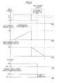
- FIG. 6 is a view showing time changes of a field current, a field current integral value, a field current limiting time counter value, and an IG signal in the field current limiting portion according to the first embodiment of the invention in a case where the IG signal is switched OFF while the field current is limited;
- FIG. 7 is a view showing time changes of the IG signal and a controller power supply connection switch according to the first embodiment of the invention in a case where the field current integral value is greater than 0;
- FIG. 8 is a view showing time changes of the IG signal and the controller power supply connection switch according to the first embodiment of the invention in a case where the field current limiting time counter value is greater than 0.
- FIG. 1 through FIG. 8 Like components are labeled with like reference numerals in the respective drawings.
- FIG. 1 is a view schematically showing the configuration when the field winding type rotary electric machine of the first embodiment is incorporated into a vehicle.
- a field winding type rotary electric machine 40 is connected to an internal combustion engine 10 via a connection portion 20 , such as a belt and pulleys.
- a battery 30 is electrically connected to the field winding type rotary electric machine 40 .
- the internal combustion engine 10 is not limited to either a gasoline engine or a diesel engine.
- the battery 30 may be dedicated to the field winding type rotary electric machine 40 or shared by a load for vehicle other than the field winding type rotary electric machine 40 .
- FIG. 2 is a view showing the configuration of the field winding type rotary electric machine 40 .
- FIG. 3 is a view showing the configuration of a field current limiting portion of the field winding type rotary electric machine 40 .
- FIG. 4 is a view showing time changes of a field current and a field current integral value in the field current limiting portion.
- the field winding type rotary electric machine 40 is formed of three prominent parts: a motor generator 50 , a power converter 60 , and a controller 70 .
- the battery 30 is connected to the power converter 60 so that the power converter 60 receives a supply of power from the outside.
- a controller power supply 170 is connected to the controller 70 and a controller power supply connection switch 160 switches ON and OFF states of a connection to the controller power supply 170 .
- the motor generator 50 includes a Y-connected or delta-connected three-phase armature winding 51 , a field winding 52 , and a current detector 53 . It should be noted that the motor generator 50 may use an armature winding 51 other than a three-phase armature winding.
- the power converter 60 includes a field winding current switching element 61 connected to the field winding 52 with a three-phase inverter, power conversion switching elements 63 a through 63 c and 64 a through 64 c connected to the respective phases of a flywheel diode 62 and the armature winding 51 .
- the controller 70 includes a gate driving portion 80 , a driving control portion 90 , a power generation control portion 100 , a field current control portion 110 , a field current detection portion 120 , a field current instruction portion 130 , a field current limiting portion 140 , a controller power supply connection determination portion 150 , and the controller power supply connection switch 160 .
- the gate driving portion 80 drives the motor generator 50 or controls power generation thereof by driving the field winding current switching element 61 and the power conversion switching elements 63 a through 63 c and 64 a through 64 c according to ON and OFF instructions for the armature winding 51 and the field winding 52 sent from the driving control portion 90 , the power generation control portion 100 , and the field current control portion 110 .
- the driving control portion 90 controls ON and OFF timings of the power conversion switching elements 63 a through 63 c and 64 a through 64 c when the motor generator 50 is driven.
- the power generation control portion 100 controls ON and OFF timings of the power conversion switching elements 63 a through 63 c and 64 a through 64 c for synchronous rectification while the motor generator 50 is generating power.
- the field current detection portion 120 detects a field current I flowing to the field winding 52 by means of the current detector 53 .
- the field current instruction portion 130 sends to the field current control portion 110 a field current instruction value I r for which the field current I is set as a control target.
- the field current limiting portion 140 determines whether the field current I is to be limited according to the field current I detected by the field current detection portion 120 . In a case where a need to limit the field current I is determined as the result, the field current limiting portion 140 sends a field current limiting value I lim to the field current control portion 110 .
- the controller power supply connection determination portion 150 switches ON and OFF the controller power supply connection switch 160 according to an ON or OFF state of an IG signal 180 inputted from the outside and an instruction from the field current limiting portion 140 .
- the field current control portion 110 upon receipt of the field current limiting value I lim from the field current limiting portion 140 , the field current control portion 110 sends a signal that controls the field current I to be flown to the field winding 52 to the gate driving portion 80 by setting the field current limiting value I lim as a control target value. It should be noted, however, that in a case where the field current instruction value I r is smaller than the field current limiting value I lim , that is, a relation, field current instruction value I r ⁇ field current limiting value I lim , is established, the field current control portion 110 sends a signal that controls the field current I to take the field current instruction value I r .
- the field current control portion 110 In a case where the field current control portion 110 does not receive the field current limiting value I lim from the field current limiting portion 140 , the field current control portion 110 constantly sends a signal that controls the field current I to be flown to the field winding 52 according to the field current instruction value I f .
- FIG. 3 showing the configuration of the field current limiting portion 140 and FIG. 4 showing time changes of the field current I and a field current integral value in the field current limiting portion 140 .
- the field current limiting portion 140 includes a storage portion 141 , a field current limiting determination portion 142 , and a field current limiting instruction portion 143 .
- the storage portion 141 includes a field current threshold storage portion 141 a , a field current integral threshold storage portion 141 b , a field current limiting value storage portion 141 c , and a field current limiting time storage portion 141 d .
- the field current limiting determination portion 142 includes a field current integrator 142 a and the field current limiting instruction portion 143 includes a field current limiting time measuring instrument 143 a.
- the field current threshold storage portion 141 a pre-stores a first field current threshold I th1 and a second field current threshold I th2 set to a value smaller than the first field current threshold I th1 .
- the relation between the first and second field current thresholds I th1 and I th2 is expressed as: first field current threshold I th1 >second field current threshold I th2 .
- the field current integral threshold storage portion 141 b pre-stores a field current integral threshold S th and the field current limiting determination portion 142 is connected thereto.
- the field current limiting value storage portion 141 c pre-stores the field current limiting value I lim .
- the field current limiting time storage portion 141 d pre-stores a field current limiting time T lim of the field current I.
- the field current limiting determination portion 142 adds a difference ⁇ I 1 between the field current I and the first field current threshold I th1 to a field current integral value S (integration in the positive direction).
- the field current limiting determination portion 142 subtracts a difference ⁇ I 2 between the second field current threshold I th2 and the field current I from the field current integral value S (integration in the negative position).
- the field current limiting determination portion 142 maintains the current field current integral value S in a case where both the following relations are established: field current I ⁇ first field current threshold I th1 and field current I ⁇ second field current threshold I th2 .
- the field current limiting determination portion 142 determines that it is necessary to limit the field current I.
- the field current limiting determination portion 142 then sends a determination result to the field current limiting instruction portion 143 .
- the second field current threshold I th2 is set so that a temperature of the field winding type rotary electric machine 40 falls within a normal range while the field winding type rotary electric machine 40 is continuously operating.
- the field current limiting value I lim is set to or below the second field current threshold value I th2 . Owing to these settings, it becomes possible to lower the temperature of the field winding type rotary electric machine 40 to a normally operable temperature in a more reliable manner.
- the field current limiting determination portion 142 clears the field current integral value S to 0.
- the field current limiting instruction portion 143 stops sending the field current limiting value I lim to the field current control portion 110 .
- the limiting of the field current I is released and the field current I is controlled according to the field current instruction value I f .
- the controller power supply connection determination portion 150 cuts off the connection between the controller 70 and the controller power supply 170 by switching OFF the controller power supply connection switch 160 .
- the controller power supply connection determination portion 150 cuts off the connection between the controller 70 and the controller power supply 170 by switching OFF the controller power supply connection switch 160 .
- the controller power supply connection determination portion 150 cuts off the connection between the controller 70 and the controller power supply 170 by switching OFF the controller power supply connection switch 160 .
- the controller power supply connection determination portion 150 cuts off the connection between the controller 70 and the controller power supply 170 by switching OFF the controller power supply connection switch 160 .
- the invention is configured in such a manner that the controller power supply connection determination portion 150 keeps the controller power supply connection switch 160 switched ON even when the IG signal 180 is switched OFF in a case where either one or both of the following conditions are satisfied:
- FIG. 7 shows an operation when the IG signal 180 is switched OFF in a case where the field current integral value S is greater than 0.
- the controller power supply connection determination portion 150 switches OFF the controller power supply connection switch 160 to cut off the connection to the controller power supply 170 .
- the controller power supply connection determination portion 150 continues to keep the controller power supply connection switch 160 switched ON according to the IG signal 180 independently of the field current integral value S.
- the controller power supply connection determination portion 150 switches OFF the controller power supply connection switch 160 to cut off the connection to the controller power supply 170 .
- the controller power supply connection determination portion 150 continues to keep the controller power supply connection switch 160 switched ON according to the IG signal 180 independently of the field current limiting time counter value C lim .
- the controller power supply connection determination portion 150 switches OFF the controller power supply connection switch 160 as soon as the IG signal 180 is switched OFF.
- the second field current threshold I th2 is set so that a temperature of the winding type rotary electric machine 40 falls within a normal range in a reliable manner while the field winding type rotary electric machine 40 is operating continuously.
- the first field current threshold value I th1 is set to a value with which the temperature of the field winding type rotary electric machine 40 rises beyond the normal range while the field winding type rotary electric machine 40 operates continuously. More specifically, when a difference between the field current I and the second field current threshold I th2 is used for integration, the field current I is limited too early in comparison with a case where a difference between the field current I and the first field current threshold I th1 is used for integration.
- An addition of the field current integral value S can be performed through computation by an internal CPU (not shown) of the controller 70 .
- the field current limiting time counter value C lim is a time measuring count value used in the field current limiting time measuring instrument 143 a of FIG. 3 .
- a rise in temperature of the field winding type rotary electric machine 40 is suppressed by forming the field winding type rotary electric machine 40 with: the motor generator 50 having the field winding 52 ; the field current detection portion 120 that detects a field current flowing to the field winding 52 ; the field current control portion 110 that controls the field current; the field current limiting determination portion 142 that calculates a field current integral value by integrating the field current over time and determines whether the calculated field current integral value has reached a predetermined field current integral threshold; the field current limiting instruction portion 143 that outputs an instruction to the field current control portion 110 to set the field current at or below a predetermined field current limiting value for a predetermined limiting time when it is determined that the calculated field current integral value has reached the predetermined field current integral threshold and outputs an instruction to change the predetermined limiting time in response to the field current; and the controller power supply connection switch 160 that switches ON and OFF the controller power supply 170 according to an instruction from the outside and
- the field winding type rotary electric machine of the first embodiment in a case where the field current is limited according to a detection result of the field current flowing to the field winding so that a temperature of the field winding type rotary electric machine does not rise excessively, when the field current integral value, which is the limiting determination value of the field current, is greater than 0 or the field current is being limited, a connection between the controller and the controller power supply is switched to an ON state independently of an instruction from the outside and the ON state is maintained until the field current integral value decreases 0 and the limiting of the field current ends. Owing to this configuration, there can be achieved a significant advantage that it becomes possible to obtain a field winding type rotary electric machine capable of preventing damaged caused by a rise in temperature in a reliable manner.
Applications Claiming Priority (2)
| Application Number | Priority Date | Filing Date | Title |
|---|---|---|---|
| JP2011-112265 | 2011-05-19 | ||
| JP2011112265A JP5566336B2 (ja) | 2011-05-19 | 2011-05-19 | 界磁巻線式回転電機 |
Publications (2)
| Publication Number | Publication Date |
|---|---|
| US20120293139A1 US20120293139A1 (en) | 2012-11-22 |
| US8829863B2 true US8829863B2 (en) | 2014-09-09 |
Family
ID=47136929
Family Applications (1)
| Application Number | Title | Priority Date | Filing Date |
|---|---|---|---|
| US13/328,400 Active 2032-11-06 US8829863B2 (en) | 2011-05-19 | 2011-12-16 | Field winding type rotary electric machine |
Country Status (3)
| Country | Link |
|---|---|
| US (1) | US8829863B2 (ja) |
| JP (1) | JP5566336B2 (ja) |
| FR (1) | FR2975548B1 (ja) |
Citations (13)
| Publication number | Priority date | Publication date | Assignee | Title |
|---|---|---|---|---|
| JPS6051421A (ja) | 1983-08-29 | 1985-03-22 | 株式会社デンソー | 車両充電発電機用制御装置 |
| JPH04229100A (ja) | 1990-06-21 | 1992-08-18 | Robert Bosch Gmbh | 発電機を調整する装置 |
| US5444354A (en) * | 1992-03-02 | 1995-08-22 | Hitachi, Ltd. | Charging generator control for vehicles |
| JPH089567A (ja) | 1994-06-23 | 1996-01-12 | Mitsubishi Electric Corp | 車両用交流発電機の出力制御方法及び出力制御装置 |
| US6121757A (en) * | 1998-02-12 | 2000-09-19 | Hitachi, Ltd. | Control device for motor vehicle use charging generator |
| US20040008009A1 (en) * | 2002-03-20 | 2004-01-15 | Mitsuo Fukaya | Portable power supply |
| US20050135133A1 (en) * | 2003-12-08 | 2005-06-23 | Denso Corporation | Control apparatus for electrical generator apparatus of motor vehicle |
| US7292007B2 (en) * | 2005-02-15 | 2007-11-06 | Denso Corporation | Vehicular electric generation control apparatus and related method of detecting electric generation status |
| US20080106240A1 (en) * | 2006-11-08 | 2008-05-08 | Mitsubishi Electric Corporation | Controller for vehicle AC generator |
| US7570027B2 (en) * | 2005-10-06 | 2009-08-04 | Denso Corporation | Electric power generation control apparatus |
| US7687929B2 (en) * | 2006-12-29 | 2010-03-30 | Cummins Power Generation Ip, Inc. | Electric power generation system with multiple inverters |
| US20100301816A1 (en) * | 2009-05-26 | 2010-12-02 | Mitsubishi Electric Corporation | Field winding type generator-motor |
| US8155795B2 (en) * | 2007-03-09 | 2012-04-10 | Sanyo Electric Co., Ltd. | Demand control system, demand controller, demand program, and demand controlling method |
Family Cites Families (3)
| Publication number | Priority date | Publication date | Assignee | Title |
|---|---|---|---|---|
| JP2941664B2 (ja) * | 1994-09-21 | 1999-08-25 | 三菱電機株式会社 | 同期機の過励磁制限装置 |
| JP2004176877A (ja) * | 2002-11-29 | 2004-06-24 | Toyota Motor Corp | トランスミッション暖機促進手段を備えた自動車 |
| JP2006271634A (ja) * | 2005-03-29 | 2006-10-12 | Fujitsu Ten Ltd | 車両の火災防止装置 |
-
2011
- 2011-05-19 JP JP2011112265A patent/JP5566336B2/ja active Active
- 2011-12-16 US US13/328,400 patent/US8829863B2/en active Active
-
2012
- 2012-01-16 FR FR1250387A patent/FR2975548B1/fr active Active
Patent Citations (18)
| Publication number | Priority date | Publication date | Assignee | Title |
|---|---|---|---|---|
| JPS6051421A (ja) | 1983-08-29 | 1985-03-22 | 株式会社デンソー | 車両充電発電機用制御装置 |
| JPH04229100A (ja) | 1990-06-21 | 1992-08-18 | Robert Bosch Gmbh | 発電機を調整する装置 |
| US5444354A (en) * | 1992-03-02 | 1995-08-22 | Hitachi, Ltd. | Charging generator control for vehicles |
| JPH089567A (ja) | 1994-06-23 | 1996-01-12 | Mitsubishi Electric Corp | 車両用交流発電機の出力制御方法及び出力制御装置 |
| US6121757A (en) * | 1998-02-12 | 2000-09-19 | Hitachi, Ltd. | Control device for motor vehicle use charging generator |
| US20040008009A1 (en) * | 2002-03-20 | 2004-01-15 | Mitsuo Fukaya | Portable power supply |
| US20050135133A1 (en) * | 2003-12-08 | 2005-06-23 | Denso Corporation | Control apparatus for electrical generator apparatus of motor vehicle |
| US7235952B2 (en) * | 2003-12-08 | 2007-06-26 | Denso Corporation | Control apparatus for electrical generator apparatus of motor vehicle |
| US7292007B2 (en) * | 2005-02-15 | 2007-11-06 | Denso Corporation | Vehicular electric generation control apparatus and related method of detecting electric generation status |
| US7570027B2 (en) * | 2005-10-06 | 2009-08-04 | Denso Corporation | Electric power generation control apparatus |
| US20080106240A1 (en) * | 2006-11-08 | 2008-05-08 | Mitsubishi Electric Corporation | Controller for vehicle AC generator |
| US7486052B2 (en) * | 2006-11-08 | 2009-02-03 | Mitsubishi Electric Corporation | Controller for vehicle AC generator |
| US7687929B2 (en) * | 2006-12-29 | 2010-03-30 | Cummins Power Generation Ip, Inc. | Electric power generation system with multiple inverters |
| US7956584B2 (en) * | 2006-12-29 | 2011-06-07 | Cummins Power Generation Ip, Inc. | Electric power generation system with multiple alternators driven by a common prime mover |
| US8155795B2 (en) * | 2007-03-09 | 2012-04-10 | Sanyo Electric Co., Ltd. | Demand control system, demand controller, demand program, and demand controlling method |
| US20100301816A1 (en) * | 2009-05-26 | 2010-12-02 | Mitsubishi Electric Corporation | Field winding type generator-motor |
| JP2010279085A (ja) | 2009-05-26 | 2010-12-09 | Mitsubishi Electric Corp | 界磁巻線式発電電動機 |
| US8334680B2 (en) * | 2009-05-26 | 2012-12-18 | Mitsubishi Electric Corporation | Field winding type generator-motor |
Also Published As
| Publication number | Publication date |
|---|---|
| FR2975548B1 (fr) | 2019-06-28 |
| FR2975548A1 (fr) | 2012-11-23 |
| JP5566336B2 (ja) | 2014-08-06 |
| JP2012244758A (ja) | 2012-12-10 |
| US20120293139A1 (en) | 2012-11-22 |
Similar Documents
| Publication | Publication Date | Title |
|---|---|---|
| US20140176085A1 (en) | Battery controller of vehicle | |
| US8736234B2 (en) | Power converter control apparatus | |
| US8680819B2 (en) | Field winding type rotary electric machine | |
| KR101898423B1 (ko) | 전원 시스템 및 그의 제어 방법 | |
| US20210044209A1 (en) | Power conversion device | |
| US8334680B2 (en) | Field winding type generator-motor | |
| JP2011173574A (ja) | 車両用異常検出装置 | |
| US9755557B2 (en) | Field-winding rotating electrical machine | |
| JP2016213918A (ja) | 車両の充電制御装置 | |
| US9007034B2 (en) | Electric power generation control system for vehicle | |
| US8829863B2 (en) | Field winding type rotary electric machine | |
| JP5192170B2 (ja) | 発電制御装置及び鞍乗型車両 | |
| US8704497B2 (en) | Control device for vehicle AC generator | |
| JP6525431B2 (ja) | バッテリ制御装置 | |
| JP2007151304A (ja) | 車両用発電機の制御装置 | |
| KR100213761B1 (ko) | 하이브리드 자동차용 보조동력장치 제어시스템 | |
| JP5974523B2 (ja) | バッテリ充電率判定方法及びバッテリ充電率判定装置 | |
| JP2006046279A (ja) | エンジン自動停止始動制御装置 | |
| KR101283254B1 (ko) | 연료저감을 위한 차량용 발전제어시스템 및 이의 제어방법 | |
| JP2011147218A (ja) | 発電制御装置 | |
| JP2012085419A (ja) | モータ回転判定方法 |
Legal Events
| Date | Code | Title | Description |
|---|---|---|---|
| AS | Assignment |
Owner name: MITSUBISHI ELECTRIC CORPORATION, JAPAN Free format text: ASSIGNMENT OF ASSIGNORS INTEREST;ASSIGNORS:AKITA, KENICHI;NAKAJIMA, KENJI;MORI, MASATO;AND OTHERS;SIGNING DATES FROM 20110921 TO 20110923;REEL/FRAME:027408/0633 |
|
| STCF | Information on status: patent grant |
Free format text: PATENTED CASE |
|
| MAFP | Maintenance fee payment |
Free format text: PAYMENT OF MAINTENANCE FEE, 4TH YEAR, LARGE ENTITY (ORIGINAL EVENT CODE: M1551) Year of fee payment: 4 |
|
| MAFP | Maintenance fee payment |
Free format text: PAYMENT OF MAINTENANCE FEE, 8TH YEAR, LARGE ENTITY (ORIGINAL EVENT CODE: M1552); ENTITY STATUS OF PATENT OWNER: LARGE ENTITY Year of fee payment: 8 |