US8808042B1 - Amphibious vehicle drive system - Google Patents

Amphibious vehicle drive system Download PDF

Info

Publication number
US8808042B1
US8808042B1 US13/932,483 US201313932483A US8808042B1 US 8808042 B1 US8808042 B1 US 8808042B1 US 201313932483 A US201313932483 A US 201313932483A US 8808042 B1 US8808042 B1 US 8808042B1
Authority
US
United States
Prior art keywords
track
drive
pair
amphibious vehicle
output shaft
Prior art date
Legal status (The legal status is an assumption and is not a legal conclusion. Google has not performed a legal analysis and makes no representation as to the accuracy of the status listed.)
Expired - Fee Related
Application number
US13/932,483
Inventor
Stanley C. Hewitt
Current Assignee (The listed assignees may be inaccurate. Google has not performed a legal analysis and makes no representation or warranty as to the accuracy of the list.)
Individual
Original Assignee
Individual
Priority date (The priority date is an assumption and is not a legal conclusion. Google has not performed a legal analysis and makes no representation as to the accuracy of the date listed.)
Filing date
Publication date
Application filed by Individual filed Critical Individual
Priority to US13/932,483 priority Critical patent/US8808042B1/en
Priority to US14/328,114 priority patent/US9022822B2/en
Application granted granted Critical
Publication of US8808042B1 publication Critical patent/US8808042B1/en
Expired - Fee Related legal-status Critical Current
Anticipated expiration legal-status Critical

Links

Images

Classifications

    • BPERFORMING OPERATIONS; TRANSPORTING
    • B60VEHICLES IN GENERAL
    • B60FVEHICLES FOR USE BOTH ON RAIL AND ON ROAD; AMPHIBIOUS OR LIKE VEHICLES; CONVERTIBLE VEHICLES
    • B60F3/00Amphibious vehicles, i.e. vehicles capable of travelling both on land and on water; Land vehicles capable of travelling under water
    • B60F3/0007Arrangement of propulsion or steering means on amphibious vehicles
    • B60F3/0015Arrangement of propulsion or steering means on amphibious vehicles comprising tracks specially adapted therefor

Definitions

  • This invention is related to an amphibious vehicle and especially to an amphibious vehicle having twin internal combustion engines propelling the vehicle in water with a pair of water jet drives and propelling the vehicle on land with one of the same engines having an automatic transmission controlling a pair of track assemblies.
  • An amphibious vehicle is a motorized vehicle capable of travel on land as well as in the water. Such vehicles are known and are capable of providing transportation either in water or on land and are useful in areas where there are bodies of water, such as lakes, rivers, swamps, and the like, which need to be traversed.
  • the amphibious vehicle allows its operator to travel across land and upon reaching the edge of a body of water, proceed into the water and continue on.
  • a drive assembly typically an assembly of wheels or caterpillar tracks that are fixed in position and cannot be retracted from the water during marine operation.
  • the inability to remove the driving assembly from the water when the vehicle is traveling in the water means the amphibious vehicle cannot be operated at a high speed in the water because of the high drag caused by the submerged driving assembly. Maneuverability in the water is also compromised by the additional drag.
  • the present invention is for an improved drive system for the amphibious vehicle as shown in my prior U.S. Patent and propels the vehicle in the water with a pair of water jet drives and propels the vehicle on land with a pair of track assemblies using an automatic transmission while using the same engine for both land and on water using a power transfer system from the output shaft of one of the engines.
  • This invention relates to an amphibious vehicle and amphibious vehicle drive system having a vehicle hull with a pair of track drive assemblies and a pair of water jet drives.
  • a pair of diesel internal combustion engines are mounted in the hull, each having an output shaft.
  • a marine transmission couples each internal combustion engine output shaft to one of the water jet drives.
  • An automatic transmission which may be a standard automobile automatic transmission, is driven by a power takeoff from one of the engines output shafts.
  • the automatic transmission is coupled to a differential having a pair of track drive shafts operatively coupled to a pair of track drive assemblies.
  • Each track drive shaft has an air clutch therein for selectively clutching one or the other track drive shafts and coupled track assembly.
  • Each track drive shaft has a planetary gear therein for selectively changing the torque applied to each track assembly.
  • An amphibious vehicle drive system is thus powered by a pair of internal combustion engines driving a pair of water jet drives in the water and for driving the vehicle on land with an automatic transmission driving a pair of track assemblies.
  • FIG. 1 is a perspective view of an amphibious vehicle having a drive train in accordance with the present invention
  • FIG. 2 is a partial perspective view of the amphibious vehicle of FIG. 1 ;
  • FIG. 3 is an exploded elevation of the power takeoff and transfer case for the amphibious vehicle of FIGS. 1 and 2 .
  • this invention is related to an amphibious vehicle 10 and especially to an amphibious vehicle having twin internal combustion engines 11 and 12 , such as two 300 hp diesel engines, propelling the vehicle in water with a pair of water jet drives 13 and 14 and propelling the vehicle 10 on land with one of the same engines having an automatic transmission 15 controlling a pair of track assemblies 16 and 17 .
  • twin internal combustion engines 11 and 12 such as two 300 hp diesel engines, propelling the vehicle in water with a pair of water jet drives 13 and 14 and propelling the vehicle 10 on land with one of the same engines having an automatic transmission 15 controlling a pair of track assemblies 16 and 17 .
  • the amphibious vehicle 10 has a hull 18 , such as a 32 foot long hull, having a cabin 19 thereon and has track drive assemblies 16 and 17 mounted on either side of the hull 18 .
  • the track assemblies 16 and 17 are arranged so that the tracks can be rotated between a lowered position as shown in FIGS. 1 and 2 and a raised position where they can rest above the water level during marine operations in accordance with my prior U.S. Patents.
  • the drive system of the present invention having a pair of diesel engines 11 and 12 powering a pair of water jet drives 13 and 14 .
  • Engine 11 has a marine transmission 20 coupled to the output of the engine.
  • the marine transmission 20 output shaft 21 is coupled to the water jet drive 13 .
  • Engine 12 has a marine transmission 22 coupled to the water jet drive 14 .
  • the water jet drives 13 and 14 propel the amphibious vehicle 10 when traveling in water with the track assemblies 16 and 17 in a raised position.
  • Amphibious vehicle engine 11 has a power takeoff 23 in a transfer case 23 coupled to the output of the output shaft of engine 11 and to the input shaft of a torque converter 24 and to an automatic transmission 15 .
  • the automatic transmission 15 is a standard six speed automobile automatic transmission coupled to the output of the diesel engine 11 through the power takeoff 23 .
  • the output shaft of the automatic transmission 15 is coupled to a differential 25 driving a pair of drive shafts 26 and 27 .
  • Each drive shaft 26 and 27 has an air clutch 28 and 30 therein which can be selectively actuated when steering the amphibious vehicle 10 on land.
  • the steering of a track vehicle is conventionally done by braking one or the other of the track assemblies, forcing the non-braked track assembly to turn the vehicle. To accomplish this however requires that the track assembly being braked also be clutched at the same time.
  • Drive shaft 27 has a planetary gear 31 therein while drive shaft 28 has a planetary gear 32 therein.
  • the planetary gears 31 and 32 may be selectively actuated to change the gear ratio, such as 2.7:1, in the drive shafts to change the torque output to each track assembly.
  • Drive shaft 26 is coupled through disc brake 33 while drive shaft 27 is coupled through a disc brake 34 , which disc brakes are used in selectively braking the track assemblies 16 and 17 to brake and steer the amphibious vehicle 10 .
  • Each drive shaft 26 and 27 is coupled to a track assembly by a sprocket driving a chain 35 .
  • hydraulic rams 36 can be seen driving a bell crank 37 and linkage 38 which raise and lower the track assemblies 16 and 17 .
  • FIG. 3 is an exploded view of the power takeoff 23 in a transfer case which is coupled to the torque converter 24 and to the automatic transmission 15 .
  • the transmission 15 is connected to the differential 25 .
  • the output of the diesel engine 11 drives a belt pulley 40 which drives a belt 41 to drive the belt pulley 42 .
  • a bearing plate 43 connects the belt pulley 42 to the belt pulley drive 44 .
  • the belt 41 and pulleys 40 and 42 are encased in a transfer casing 45 .
  • the belt 41 transfers power from the output shaft of engine 11 to the torque converter 24 through a torque converter bearing and flex plate housed in a bell housing 48 .
  • the track assemblies 16 and 17 are in a raised position and the marine transmissions 20 and 22 are engaged to have the engines 11 and 12 drive the water jet drives 13 and 14 to propel the amphibious vehicle 10 across the water.
  • the track assemblies 16 and 17 are lowered and the automatic transmission 15 engaged from idle to drive.
  • the transmission 15 is being powered by engine 11 through the power takeoff 23 and remains in idle when the tracks 16 and 17 are raised.
  • the transmission 15 drives the differential 25 and both drive shafts 26 and 27 through the different gear ratios of the automatic transmission 15 .
  • the amphibious vehicle 10 is driven and steered by the activation of the air clutches 28 and 30 and the disc brakes 33 and 34 .
  • the planetary gears 31 and 32 can gear down each shaft 26 or 27 and thereby increase the torque to each track assembly 16 or 17 separately.

Abstract

This invention relates to an amphibious vehicle and especially to an amphibious vehicle having twin internal combustion engines propelling the vehicle in water with a pair of water jet drives and propelling the vehicle on land with one of the same engines having an automatic transmission controlling a pair of track assemblies with a pair of planetary gears, clutches and disc brakes.

Description

FIELD OF THE INVENTION
This invention is related to an amphibious vehicle and especially to an amphibious vehicle having twin internal combustion engines propelling the vehicle in water with a pair of water jet drives and propelling the vehicle on land with one of the same engines having an automatic transmission controlling a pair of track assemblies.
BACKGROUND OF THE INVENTION
An amphibious vehicle is a motorized vehicle capable of travel on land as well as in the water. Such vehicles are known and are capable of providing transportation either in water or on land and are useful in areas where there are bodies of water, such as lakes, rivers, swamps, and the like, which need to be traversed. The amphibious vehicle allows its operator to travel across land and upon reaching the edge of a body of water, proceed into the water and continue on.
Many amphibious vehicles use a drive assembly, typically an assembly of wheels or caterpillar tracks that are fixed in position and cannot be retracted from the water during marine operation. The inability to remove the driving assembly from the water when the vehicle is traveling in the water means the amphibious vehicle cannot be operated at a high speed in the water because of the high drag caused by the submerged driving assembly. Maneuverability in the water is also compromised by the additional drag.
In my prior U.S. Pat. No. 7,950,973 for an Amphibious Vehicle, I show an improved amphibious vehicle which allows the track assemblies to be rotated between a lower position supporting the amphibious vehicle on land while providing propulsion to the vehicle on land and a raised position where the tracks rest vertically above the hull's deck during marine operation. With the caterpillar track assemblies fully removed from the water, the vehicle's performance and maneuverability are improved. The track assemblies are hydraulically driven to rotate the wheels and tracks between a lowered and a raised position. The present application is an improved drive system for the vehicle in this prior U.S. Patent and the contents of this earlier patent is incorporated herein by reference in its entirety.
In my prior U.S. Pat. No. 6,921,304 for an Amphibious Vehicle, I show an earlier improved amphibious vehicle which allows the track assemblies to be rotated between raised and lowered positions. In this prior patent the tracks are raised and lowered by a lifting mechanism which lifts the tracks and then pulls the tracks inward toward the hull of the vehicle using hydraulic rams. The lifting and pulling lifts the tracks into a fully upright position onto the hull to reduce the overall width of the amphibious vehicle to facilitate trailering.
The present invention is for an improved drive system for the amphibious vehicle as shown in my prior U.S. Patent and propels the vehicle in the water with a pair of water jet drives and propels the vehicle on land with a pair of track assemblies using an automatic transmission while using the same engine for both land and on water using a power transfer system from the output shaft of one of the engines.
SUMMARY OF THE INVENTION
This invention relates to an amphibious vehicle and amphibious vehicle drive system having a vehicle hull with a pair of track drive assemblies and a pair of water jet drives. A pair of diesel internal combustion engines are mounted in the hull, each having an output shaft. A marine transmission couples each internal combustion engine output shaft to one of the water jet drives. An automatic transmission, which may be a standard automobile automatic transmission, is driven by a power takeoff from one of the engines output shafts. The automatic transmission is coupled to a differential having a pair of track drive shafts operatively coupled to a pair of track drive assemblies. Each track drive shaft has an air clutch therein for selectively clutching one or the other track drive shafts and coupled track assembly. Each track drive shaft has a planetary gear therein for selectively changing the torque applied to each track assembly. An amphibious vehicle drive system is thus powered by a pair of internal combustion engines driving a pair of water jet drives in the water and for driving the vehicle on land with an automatic transmission driving a pair of track assemblies.
BRIEF DESCRIPTION OF THE DRAWINGS
The accompanying drawings, which are included to provide further understanding of the invention are incorporated in and constitute a part of the specification, and illustrate an embodiment of the invention and together with the description serve to explain the principles of the invention.
In the drawings:
FIG. 1 is a perspective view of an amphibious vehicle having a drive train in accordance with the present invention;
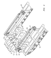
FIG. 2 is a partial perspective view of the amphibious vehicle of FIG. 1; and
FIG. 3 is an exploded elevation of the power takeoff and transfer case for the amphibious vehicle of FIGS. 1 and 2.
DETAILED DESCRIPTION OF EXEMPLARY EMBODIMENT
As seen in FIGS. 1-3 of the drawings, this invention is related to an amphibious vehicle 10 and especially to an amphibious vehicle having twin internal combustion engines 11 and 12, such as two 300 hp diesel engines, propelling the vehicle in water with a pair of water jet drives 13 and 14 and propelling the vehicle 10 on land with one of the same engines having an automatic transmission 15 controlling a pair of track assemblies 16 and 17.
In FIGS. 1 and 2, the amphibious vehicle 10 has a hull 18, such as a 32 foot long hull, having a cabin 19 thereon and has track drive assemblies 16 and 17 mounted on either side of the hull 18. The track assemblies 16 and 17 are arranged so that the tracks can be rotated between a lowered position as shown in FIGS. 1 and 2 and a raised position where they can rest above the water level during marine operations in accordance with my prior U.S. Patents.
The drive system of the present invention, as more clearly seen in connection with FIGS. 1 and 2, having a pair of diesel engines 11 and 12 powering a pair of water jet drives 13 and 14. Engine 11 has a marine transmission 20 coupled to the output of the engine. The marine transmission 20 output shaft 21 is coupled to the water jet drive 13. Engine 12 has a marine transmission 22 coupled to the water jet drive 14. The water jet drives 13 and 14 propel the amphibious vehicle 10 when traveling in water with the track assemblies 16 and 17 in a raised position. Amphibious vehicle engine 11 has a power takeoff 23 in a transfer case 23 coupled to the output of the output shaft of engine 11 and to the input shaft of a torque converter 24 and to an automatic transmission 15. The automatic transmission 15 is a standard six speed automobile automatic transmission coupled to the output of the diesel engine 11 through the power takeoff 23.
The output shaft of the automatic transmission 15 is coupled to a differential 25 driving a pair of drive shafts 26 and 27. Each drive shaft 26 and 27 has an air clutch 28 and 30 therein which can be selectively actuated when steering the amphibious vehicle 10 on land. The steering of a track vehicle is conventionally done by braking one or the other of the track assemblies, forcing the non-braked track assembly to turn the vehicle. To accomplish this however requires that the track assembly being braked also be clutched at the same time. Drive shaft 27 has a planetary gear 31 therein while drive shaft 28 has a planetary gear 32 therein. The planetary gears 31 and 32 may be selectively actuated to change the gear ratio, such as 2.7:1, in the drive shafts to change the torque output to each track assembly. This arrangement gives the vehicle a 120 to 1 gear reduction in the transmission's low gear with the planetary gears engaged and a 32 to 1 with the planetary gears in direct drive. Drive shaft 26 is coupled through disc brake 33 while drive shaft 27 is coupled through a disc brake 34, which disc brakes are used in selectively braking the track assemblies 16 and 17 to brake and steer the amphibious vehicle 10. Each drive shaft 26 and 27 is coupled to a track assembly by a sprocket driving a chain 35. In FIG. 2, hydraulic rams 36 can be seen driving a bell crank 37 and linkage 38 which raise and lower the track assemblies 16 and 17.
FIG. 3 is an exploded view of the power takeoff 23 in a transfer case which is coupled to the torque converter 24 and to the automatic transmission 15. The transmission 15 is connected to the differential 25. The output of the diesel engine 11 drives a belt pulley 40 which drives a belt 41 to drive the belt pulley 42. A bearing plate 43 connects the belt pulley 42 to the belt pulley drive 44. The belt 41 and pulleys 40 and 42 are encased in a transfer casing 45. The belt 41 transfers power from the output shaft of engine 11 to the torque converter 24 through a torque converter bearing and flex plate housed in a bell housing 48.
In operation in water, the track assemblies 16 and 17 are in a raised position and the marine transmissions 20 and 22 are engaged to have the engines 11 and 12 drive the water jet drives 13 and 14 to propel the amphibious vehicle 10 across the water. On land, the track assemblies 16 and 17 are lowered and the automatic transmission 15 engaged from idle to drive. The transmission 15 is being powered by engine 11 through the power takeoff 23 and remains in idle when the tracks 16 and 17 are raised. When in gear, the transmission 15 drives the differential 25 and both drive shafts 26 and 27 through the different gear ratios of the automatic transmission 15. The amphibious vehicle 10 is driven and steered by the activation of the air clutches 28 and 30 and the disc brakes 33 and 34. The planetary gears 31 and 32 can gear down each shaft 26 or 27 and thereby increase the torque to each track assembly 16 or 17 separately.
It should be clear at this time that an amphibious vehicle and amphibious vehicle drive system have been provided. However the present invention is not to be considered limited to the forms shown which are to be considered illustrative rather than restrictive.

Claims (14)

I claim:
1. An amphibious vehicle drive system comprising:
a vehicle hull having a pair of track drive assemblies and at least one water jet drive;
at least one internal combustion engine mounted in said hull and having an output shaft therefrom;
a marine transmission coupling said internal combustion engine output shaft to said water jet drive;
an automatic transmission;
a transfer case coupling said output shaft to said automatic transmission;
a differential coupling said automatic transmission to a pair of track drive shafts, each track drive shaft being operatively coupled to one of said pair of track drive assemblies;
a pair of clutches, each clutch located in one of said pair of track drive shafts for selectively clutching one or the other track drive shafts and coupled track assembly; and
a planetary gear mounted in each track drive shaft for selectively changing the torque in each track drive shaft and track assembly;
whereby said amphibious vehicle drive system is powered by said at least one internal combustion engine selectively driving said at least one water jet drive and the automatic transmission driving the pair of track assemblies.
2. The amphibious vehicle drive system in accordance with claim 1 in which each of said pair of clutches is an air clutch individually controlled.
3. The amphibious vehicle drive system in accordance with claim 2 including a pair of disc brakes each being operatively coupled to one of said pair of track drive shafts.
4. The amphibious vehicle drive system in accordance with claim 3 having a chain drive for each track drive assembly driven by one said track drive shaft.
5. The amphibious vehicle drive system in accordance with claim 1 in which each said chain drive includes a sprocket attached to said track drive shaft having a chain thereon for driving said track drive assembly.
6. The amphibious vehicle drive system in accordance with claim 5 wherein said at least one internal combustion engine includes a pair of internal combustion engines each driving a water jet drive.
7. The amphibious vehicle drive system in accordance with claim 6 in which each said combustion engine is a diesel engine.
8. The amphibious vehicle drive system in accordance with claim 5 in which said automatic transmission includes a torque converter.
9. The amphibious vehicle drive system in accordance with claim 5 in which said transfer case includes an engine output shaft pulley coupled to said engine output shaft and transmission drive pulley coupled to said torque converter, and a belt coupled between said engine output shaft pulley and said transmission drive pulley.
10. An amphibious vehicle drive system comprising:
a vehicle hull having a pair of track drive assemblies and two water jet drives;
two internal combustion engines mounted in said hull, each having an output shaft therefrom;
a marine transmission coupling to each said internal combustion engine output shaft to said water jet drive;
an automatic transmission;
a transfer case coupling the output shaft of one of said internal combustion engines to said automatic transmission;
a differential coupling said automatic transmission to a pair of track drive shafts, each track drive shaft being operatively coupled to one of said pair of track drive assemblies;
a pair of clutches, each clutch located in one of said pair of track drive shafts for selectively clutching one or the other track drive shafts and coupled track assembly; and
a planetary gear mounted in each track drive shaft for selectively changing the torque in each track drive shaft and track drive assembly;
whereby said amphibious vehicle drive system is powered by the two internal combustion engines driving the two water jet drives and the automatic transmission driving the pair of track assemblies.
11. The amphibious vehicle drive system in accordance with claim 10 in which said two internal combustion engines are diesel engines.
12. The amphibious vehicle drive system in accordance with claim 11 in which each of said pair of clutches is an air clutch individually controlled.
13. The amphibious vehicle drive system in accordance with claim 12 including a pair of disc brakes each disc brake being operatively coupled to one of said pair of track drive shafts for braking each said track assembly.
14. The amphibious vehicle drive system in accordance with claim 13 in which said transfer case includes an engine output shaft pulley coupled to said engine output shaft and a transmission drive pulley coupled to said torque converter, and a belt coupled between said engine output shaft pulley and said transmission drive pulley for driving said automatic transmission from one engine output shaft.
US13/932,483 2013-07-01 2013-07-01 Amphibious vehicle drive system Expired - Fee Related US8808042B1 (en)

Priority Applications (2)

Application Number Priority Date Filing Date Title
US13/932,483 US8808042B1 (en) 2013-07-01 2013-07-01 Amphibious vehicle drive system
US14/328,114 US9022822B2 (en) 2013-07-01 2014-07-10 Amphibious vehicle electric drive system

Applications Claiming Priority (1)

Application Number Priority Date Filing Date Title
US13/932,483 US8808042B1 (en) 2013-07-01 2013-07-01 Amphibious vehicle drive system

Related Child Applications (1)

Application Number Title Priority Date Filing Date
US14/328,114 Continuation-In-Part US9022822B2 (en) 2013-07-01 2014-07-10 Amphibious vehicle electric drive system

Publications (1)

Publication Number Publication Date
US8808042B1 true US8808042B1 (en) 2014-08-19

Family

ID=51301586

Family Applications (1)

Application Number Title Priority Date Filing Date
US13/932,483 Expired - Fee Related US8808042B1 (en) 2013-07-01 2013-07-01 Amphibious vehicle drive system

Country Status (1)

Country Link
US (1) US8808042B1 (en)

Cited By (12)

* Cited by examiner, † Cited by third party
Publication number Priority date Publication date Assignee Title
US9022822B2 (en) * 2013-07-01 2015-05-05 Stanley C Hewitt Amphibious vehicle electric drive system
US20160176254A1 (en) * 2012-04-13 2016-06-23 Aeplog, Inc. Modularized containerized amphibious vehicle transport
CN106080432A (en) * 2016-08-04 2016-11-09 代兴 A kind of chassis type vehicle water-tight device and system
CN106394147A (en) * 2016-12-24 2017-02-15 宁波市镇海捷登应用技术研究所 Water-beach two-purpose ship
EP3222499A1 (en) * 2016-03-24 2017-09-27 Kässbohrer Geländefahrzeug AG Civil tracked vehicle
CN107839417A (en) * 2017-10-17 2018-03-27 青岛中邦防务智能装备有限公司 A kind of application method of amphibious unmanned boat caterpillar system
CN108253231A (en) * 2016-06-23 2018-07-06 文秀 A kind of shooting, collecting is intelligently equipped
US10053198B1 (en) * 2017-01-28 2018-08-21 Alcee John Thibodeaux Crawfish track system
US10106004B2 (en) 2013-12-27 2018-10-23 Mitsubishi Heavy Industries, Ltd. Amphibious vehicle
US10604200B2 (en) 2016-12-14 2020-03-31 Ontario Drive & Gear Limited All-terrain vehicle
US11358636B2 (en) 2016-12-21 2022-06-14 Ontario Drive & Gear Limited Vehicle drive transmission and electrically assisted steering system
US11919345B2 (en) 2022-05-23 2024-03-05 J. David March Amphibious vehicle

Citations (8)

* Cited by examiner, † Cited by third party
Publication number Priority date Publication date Assignee Title
US3486477A (en) * 1968-02-12 1969-12-30 David R Pender Amphibian vehicle
US4712636A (en) * 1985-05-29 1987-12-15 Kawasaki Jukogyo Kabushiki Kaisha Carriage for watercraft
US6764358B2 (en) * 2000-08-26 2004-07-20 Gibbs Technologies Ltd. Amphibious vehicle
US6821166B2 (en) * 2000-08-25 2004-11-23 Gibbs Technologies Limited Power train
US6921304B2 (en) 2003-06-18 2005-07-26 Stanley C. Hewitt Amphibious vehicle
US7011557B2 (en) * 2001-02-01 2006-03-14 Gibbs Technologies Limited Amphibious vehicle
US7410396B2 (en) * 2004-10-22 2008-08-12 Gibbs Technologies Ltd Amphibious vehicle transmission
US7950973B2 (en) 2007-12-18 2011-05-31 Hewitt Stanley C Amphibious vehicle

Patent Citations (8)

* Cited by examiner, † Cited by third party
Publication number Priority date Publication date Assignee Title
US3486477A (en) * 1968-02-12 1969-12-30 David R Pender Amphibian vehicle
US4712636A (en) * 1985-05-29 1987-12-15 Kawasaki Jukogyo Kabushiki Kaisha Carriage for watercraft
US6821166B2 (en) * 2000-08-25 2004-11-23 Gibbs Technologies Limited Power train
US6764358B2 (en) * 2000-08-26 2004-07-20 Gibbs Technologies Ltd. Amphibious vehicle
US7011557B2 (en) * 2001-02-01 2006-03-14 Gibbs Technologies Limited Amphibious vehicle
US6921304B2 (en) 2003-06-18 2005-07-26 Stanley C. Hewitt Amphibious vehicle
US7410396B2 (en) * 2004-10-22 2008-08-12 Gibbs Technologies Ltd Amphibious vehicle transmission
US7950973B2 (en) 2007-12-18 2011-05-31 Hewitt Stanley C Amphibious vehicle

Cited By (17)

* Cited by examiner, † Cited by third party
Publication number Priority date Publication date Assignee Title
US20160176254A1 (en) * 2012-04-13 2016-06-23 Aeplog, Inc. Modularized containerized amphibious vehicle transport
US9022822B2 (en) * 2013-07-01 2015-05-05 Stanley C Hewitt Amphibious vehicle electric drive system
US10106004B2 (en) 2013-12-27 2018-10-23 Mitsubishi Heavy Industries, Ltd. Amphibious vehicle
EP3222499A1 (en) * 2016-03-24 2017-09-27 Kässbohrer Geländefahrzeug AG Civil tracked vehicle
RU2683210C2 (en) * 2016-03-24 2019-03-26 Кессборер Гелендефарцойг АГ Civilian tracked vehicle
CN108253231A (en) * 2016-06-23 2018-07-06 文秀 A kind of shooting, collecting is intelligently equipped
CN106080432A (en) * 2016-08-04 2016-11-09 代兴 A kind of chassis type vehicle water-tight device and system
CN106080432B (en) * 2016-08-04 2018-04-13 重庆电子工程职业学院 A kind of chassis type vehicle water-tight device and system
US10604200B2 (en) 2016-12-14 2020-03-31 Ontario Drive & Gear Limited All-terrain vehicle
US11685436B2 (en) 2016-12-21 2023-06-27 Ontario Drive & Gear Limited Vehicle drive transmission and electrically assisted steering system
US11358636B2 (en) 2016-12-21 2022-06-14 Ontario Drive & Gear Limited Vehicle drive transmission and electrically assisted steering system
CN106394147B (en) * 2016-12-24 2019-12-31 宁波市镇海捷登应用技术研究所 Water and beach dual-purpose ship
CN106394147A (en) * 2016-12-24 2017-02-15 宁波市镇海捷登应用技术研究所 Water-beach two-purpose ship
US10053198B1 (en) * 2017-01-28 2018-08-21 Alcee John Thibodeaux Crawfish track system
CN107839417B (en) * 2017-10-17 2019-06-21 青岛中邦防务智能装备有限公司 A kind of application method of amphibious unmanned boat caterpillar system
CN107839417A (en) * 2017-10-17 2018-03-27 青岛中邦防务智能装备有限公司 A kind of application method of amphibious unmanned boat caterpillar system
US11919345B2 (en) 2022-05-23 2024-03-05 J. David March Amphibious vehicle

Similar Documents

Publication Publication Date Title
US8808042B1 (en) Amphibious vehicle drive system
US9022822B2 (en) Amphibious vehicle electric drive system
US7950973B2 (en) Amphibious vehicle
CA2583219C (en) Amphibious vehicle speed change transmission arrangement
US7214112B2 (en) Amphibious vehicle
CA2712337C (en) Vehicle drive transmission and steering system
JP2006528100A (en) Multi-speed transmission
RU2003107951A (en) TRANSMISSION AND CAR-AMPHIBIA
JP2006528100A5 (en)
US20110028055A1 (en) Amphibious All-Terrain Vehicle
CA2677010A1 (en) Tracked amphibious vehicle and adaptable amphibious tracking system
CN103085618B (en) Amphibious boat
US20090156069A1 (en) Amphibious vehicle
US6575796B1 (en) Amphibious vehicle drive train
US4124124A (en) Hydraulic control and drive system for amphibious vehicle having a topside dragline draw works thereon
CN201400091Y (en) Automobile capable of self rescuing during breakdowns
CN107771132A (en) Dynamical system for duck
CN201456963U (en) Double-body amphibious tourist automobile
RU147488U1 (en) PONTON TRAILER
US20050014425A1 (en) Drive system for amphibious equipment
JP3019727U (en) Rail carrier
CN87103918A (en) Boat type two-purpose vehicle for travelling on beach and shallow sea
CN2286119Y (en) Two-purpose boat in water and on land
RU211175U1 (en) SMALL TRACKED MACHINE
KR101781490B1 (en) drive device of snow plow

Legal Events

Date Code Title Description
STCF Information on status: patent grant

Free format text: PATENTED CASE

MAFP Maintenance fee payment

Free format text: PAYMENT OF MAINTENANCE FEE, 4TH YEAR, MICRO ENTITY (ORIGINAL EVENT CODE: M3551)

Year of fee payment: 4

FEPP Fee payment procedure

Free format text: MAINTENANCE FEE REMINDER MAILED (ORIGINAL EVENT CODE: REM.); ENTITY STATUS OF PATENT OWNER: MICROENTITY

LAPS Lapse for failure to pay maintenance fees

Free format text: PATENT EXPIRED FOR FAILURE TO PAY MAINTENANCE FEES (ORIGINAL EVENT CODE: EXP.); ENTITY STATUS OF PATENT OWNER: MICROENTITY

STCH Information on status: patent discontinuation

Free format text: PATENT EXPIRED DUE TO NONPAYMENT OF MAINTENANCE FEES UNDER 37 CFR 1.362

FP Lapsed due to failure to pay maintenance fee

Effective date: 20220819