JP2006528100A - Multi-speed transmission - Google Patents
Multi-speed transmission Download PDFInfo
- Publication number
- JP2006528100A JP2006528100A JP2006520631A JP2006520631A JP2006528100A JP 2006528100 A JP2006528100 A JP 2006528100A JP 2006520631 A JP2006520631 A JP 2006520631A JP 2006520631 A JP2006520631 A JP 2006520631A JP 2006528100 A JP2006528100 A JP 2006528100A
- Authority
- JP
- Japan
- Prior art keywords
- gear
- shaft
- output shaft
- clutch
- input shaft
- Prior art date
- Legal status (The legal status is an assumption and is not a legal conclusion. Google has not performed a legal analysis and makes no representation as to the accuracy of the status listed.)
- Pending
Links
Images


Classifications
-
- B—PERFORMING OPERATIONS; TRANSPORTING
- B63—SHIPS OR OTHER WATERBORNE VESSELS; RELATED EQUIPMENT
- B63H—MARINE PROPULSION OR STEERING
- B63H20/00—Outboard propulsion units, e.g. outboard motors or Z-drives; Arrangements thereof on vessels
- B63H20/14—Transmission between propulsion power unit and propulsion element
- B63H20/20—Transmission between propulsion power unit and propulsion element with provision for reverse drive
-
- B—PERFORMING OPERATIONS; TRANSPORTING
- B63—SHIPS OR OTHER WATERBORNE VESSELS; RELATED EQUIPMENT
- B63H—MARINE PROPULSION OR STEERING
- B63H23/00—Transmitting power from propulsion power plant to propulsive elements
- B63H23/02—Transmitting power from propulsion power plant to propulsive elements with mechanical gearing
- B63H23/06—Transmitting power from propulsion power plant to propulsive elements with mechanical gearing for transmitting drive from a single propulsion power unit
-
- B—PERFORMING OPERATIONS; TRANSPORTING
- B63—SHIPS OR OTHER WATERBORNE VESSELS; RELATED EQUIPMENT
- B63H—MARINE PROPULSION OR STEERING
- B63H23/00—Transmitting power from propulsion power plant to propulsive elements
- B63H23/30—Transmitting power from propulsion power plant to propulsive elements characterised by use of clutches
-
- F—MECHANICAL ENGINEERING; LIGHTING; HEATING; WEAPONS; BLASTING
- F16—ENGINEERING ELEMENTS AND UNITS; GENERAL MEASURES FOR PRODUCING AND MAINTAINING EFFECTIVE FUNCTIONING OF MACHINES OR INSTALLATIONS; THERMAL INSULATION IN GENERAL
- F16H—GEARING
- F16H3/00—Toothed gearings for conveying rotary motion with variable gear ratio or for reversing rotary motion
- F16H3/02—Toothed gearings for conveying rotary motion with variable gear ratio or for reversing rotary motion without gears having orbital motion
- F16H3/08—Toothed gearings for conveying rotary motion with variable gear ratio or for reversing rotary motion without gears having orbital motion exclusively or essentially with continuously meshing gears, that can be disengaged from their shafts
- F16H3/087—Toothed gearings for conveying rotary motion with variable gear ratio or for reversing rotary motion without gears having orbital motion exclusively or essentially with continuously meshing gears, that can be disengaged from their shafts characterised by the disposition of the gears
- F16H3/091—Toothed gearings for conveying rotary motion with variable gear ratio or for reversing rotary motion without gears having orbital motion exclusively or essentially with continuously meshing gears, that can be disengaged from their shafts characterised by the disposition of the gears including a single countershaft
-
- F—MECHANICAL ENGINEERING; LIGHTING; HEATING; WEAPONS; BLASTING
- F16—ENGINEERING ELEMENTS AND UNITS; GENERAL MEASURES FOR PRODUCING AND MAINTAINING EFFECTIVE FUNCTIONING OF MACHINES OR INSTALLATIONS; THERMAL INSULATION IN GENERAL
- F16H—GEARING
- F16H3/00—Toothed gearings for conveying rotary motion with variable gear ratio or for reversing rotary motion
- F16H3/02—Toothed gearings for conveying rotary motion with variable gear ratio or for reversing rotary motion without gears having orbital motion
- F16H3/08—Toothed gearings for conveying rotary motion with variable gear ratio or for reversing rotary motion without gears having orbital motion exclusively or essentially with continuously meshing gears, that can be disengaged from their shafts
- F16H3/10—Toothed gearings for conveying rotary motion with variable gear ratio or for reversing rotary motion without gears having orbital motion exclusively or essentially with continuously meshing gears, that can be disengaged from their shafts with one or more one-way clutches as an essential feature
-
- B—PERFORMING OPERATIONS; TRANSPORTING
- B63—SHIPS OR OTHER WATERBORNE VESSELS; RELATED EQUIPMENT
- B63H—MARINE PROPULSION OR STEERING
- B63H23/00—Transmitting power from propulsion power plant to propulsive elements
- B63H23/02—Transmitting power from propulsion power plant to propulsive elements with mechanical gearing
- B63H2023/0258—Transmitting power from propulsion power plant to propulsive elements with mechanical gearing comprising gearings with variable gear ratio, other than reversing drives or trolling drives
-
- B—PERFORMING OPERATIONS; TRANSPORTING
- B63—SHIPS OR OTHER WATERBORNE VESSELS; RELATED EQUIPMENT
- B63H—MARINE PROPULSION OR STEERING
- B63H23/00—Transmitting power from propulsion power plant to propulsive elements
- B63H23/02—Transmitting power from propulsion power plant to propulsive elements with mechanical gearing
- B63H2023/0283—Transmitting power from propulsion power plant to propulsive elements with mechanical gearing using gears having orbital motion
-
- F—MECHANICAL ENGINEERING; LIGHTING; HEATING; WEAPONS; BLASTING
- F16—ENGINEERING ELEMENTS AND UNITS; GENERAL MEASURES FOR PRODUCING AND MAINTAINING EFFECTIVE FUNCTIONING OF MACHINES OR INSTALLATIONS; THERMAL INSULATION IN GENERAL
- F16H—GEARING
- F16H1/00—Toothed gearings for conveying rotary motion
- F16H1/02—Toothed gearings for conveying rotary motion without gears having orbital motion
- F16H1/04—Toothed gearings for conveying rotary motion without gears having orbital motion involving only two intermeshing members
- F16H1/12—Toothed gearings for conveying rotary motion without gears having orbital motion involving only two intermeshing members with non-parallel axes
- F16H1/14—Toothed gearings for conveying rotary motion without gears having orbital motion involving only two intermeshing members with non-parallel axes comprising conical gears only
- F16H1/145—Toothed gearings for conveying rotary motion without gears having orbital motion involving only two intermeshing members with non-parallel axes comprising conical gears only with offset axes, e.g. hypoïd gearings
-
- F—MECHANICAL ENGINEERING; LIGHTING; HEATING; WEAPONS; BLASTING
- F16—ENGINEERING ELEMENTS AND UNITS; GENERAL MEASURES FOR PRODUCING AND MAINTAINING EFFECTIVE FUNCTIONING OF MACHINES OR INSTALLATIONS; THERMAL INSULATION IN GENERAL
- F16H—GEARING
- F16H2200/00—Transmissions for multiple ratios
- F16H2200/003—Transmissions for multiple ratios characterised by the number of forward speeds
- F16H2200/0034—Transmissions for multiple ratios characterised by the number of forward speeds the gear ratios comprising two forward speeds
-
- F—MECHANICAL ENGINEERING; LIGHTING; HEATING; WEAPONS; BLASTING
- F16—ENGINEERING ELEMENTS AND UNITS; GENERAL MEASURES FOR PRODUCING AND MAINTAINING EFFECTIVE FUNCTIONING OF MACHINES OR INSTALLATIONS; THERMAL INSULATION IN GENERAL
- F16H—GEARING
- F16H2200/00—Transmissions for multiple ratios
- F16H2200/0082—Transmissions for multiple ratios characterised by the number of reverse speeds
- F16H2200/0086—Transmissions for multiple ratios characterised by the number of reverse speeds the gear ratios comprising two reverse speeds
-
- F—MECHANICAL ENGINEERING; LIGHTING; HEATING; WEAPONS; BLASTING
- F16—ENGINEERING ELEMENTS AND UNITS; GENERAL MEASURES FOR PRODUCING AND MAINTAINING EFFECTIVE FUNCTIONING OF MACHINES OR INSTALLATIONS; THERMAL INSULATION IN GENERAL
- F16H—GEARING
- F16H3/00—Toothed gearings for conveying rotary motion with variable gear ratio or for reversing rotary motion
- F16H3/02—Toothed gearings for conveying rotary motion with variable gear ratio or for reversing rotary motion without gears having orbital motion
- F16H3/08—Toothed gearings for conveying rotary motion with variable gear ratio or for reversing rotary motion without gears having orbital motion exclusively or essentially with continuously meshing gears, that can be disengaged from their shafts
- F16H3/087—Toothed gearings for conveying rotary motion with variable gear ratio or for reversing rotary motion without gears having orbital motion exclusively or essentially with continuously meshing gears, that can be disengaged from their shafts characterised by the disposition of the gears
-
- F—MECHANICAL ENGINEERING; LIGHTING; HEATING; WEAPONS; BLASTING
- F16—ENGINEERING ELEMENTS AND UNITS; GENERAL MEASURES FOR PRODUCING AND MAINTAINING EFFECTIVE FUNCTIONING OF MACHINES OR INSTALLATIONS; THERMAL INSULATION IN GENERAL
- F16H—GEARING
- F16H3/00—Toothed gearings for conveying rotary motion with variable gear ratio or for reversing rotary motion
- F16H3/02—Toothed gearings for conveying rotary motion with variable gear ratio or for reversing rotary motion without gears having orbital motion
- F16H3/08—Toothed gearings for conveying rotary motion with variable gear ratio or for reversing rotary motion without gears having orbital motion exclusively or essentially with continuously meshing gears, that can be disengaged from their shafts
- F16H3/14—Gearings for reversal only
- F16H3/145—Gearings for reversal only with a pair of coaxial bevel gears, rotatable in opposite directions
-
- Y—GENERAL TAGGING OF NEW TECHNOLOGICAL DEVELOPMENTS; GENERAL TAGGING OF CROSS-SECTIONAL TECHNOLOGIES SPANNING OVER SEVERAL SECTIONS OF THE IPC; TECHNICAL SUBJECTS COVERED BY FORMER USPC CROSS-REFERENCE ART COLLECTIONS [XRACs] AND DIGESTS
- Y10—TECHNICAL SUBJECTS COVERED BY FORMER USPC
- Y10T—TECHNICAL SUBJECTS COVERED BY FORMER US CLASSIFICATION
- Y10T74/00—Machine element or mechanism
- Y10T74/19—Gearing
- Y10T74/19219—Interchangeably locked
- Y10T74/19228—Multiple concentric clutch shafts
-
- Y—GENERAL TAGGING OF NEW TECHNOLOGICAL DEVELOPMENTS; GENERAL TAGGING OF CROSS-SECTIONAL TECHNOLOGIES SPANNING OVER SEVERAL SECTIONS OF THE IPC; TECHNICAL SUBJECTS COVERED BY FORMER USPC CROSS-REFERENCE ART COLLECTIONS [XRACs] AND DIGESTS
- Y10—TECHNICAL SUBJECTS COVERED BY FORMER USPC
- Y10T—TECHNICAL SUBJECTS COVERED BY FORMER US CLASSIFICATION
- Y10T74/00—Machine element or mechanism
- Y10T74/19—Gearing
- Y10T74/19219—Interchangeably locked
- Y10T74/19251—Control mechanism
-
- Y—GENERAL TAGGING OF NEW TECHNOLOGICAL DEVELOPMENTS; GENERAL TAGGING OF CROSS-SECTIONAL TECHNOLOGIES SPANNING OVER SEVERAL SECTIONS OF THE IPC; TECHNICAL SUBJECTS COVERED BY FORMER USPC CROSS-REFERENCE ART COLLECTIONS [XRACs] AND DIGESTS
- Y10—TECHNICAL SUBJECTS COVERED BY FORMER USPC
- Y10T—TECHNICAL SUBJECTS COVERED BY FORMER US CLASSIFICATION
- Y10T74/00—Machine element or mechanism
- Y10T74/19—Gearing
- Y10T74/19219—Interchangeably locked
- Y10T74/19284—Meshing assisters
- Y10T74/19288—Double clutch and interposed transmission
Landscapes
- Engineering & Computer Science (AREA)
- Mechanical Engineering (AREA)
- Chemical & Material Sciences (AREA)
- Combustion & Propulsion (AREA)
- Ocean & Marine Engineering (AREA)
- General Engineering & Computer Science (AREA)
- Structure Of Transmissions (AREA)
- Control Of Transmission Device (AREA)
- Hydraulic Clutches, Magnetic Clutches, Fluid Clutches, And Fluid Joints (AREA)
Abstract
入力シャフトを同軸の出力シャフトに接続するための第1クラッチ、典型的には入力シャフトおよび出力シャフトに対して平行である副シャフト、前記のものを入力シャフトを介して駆動するために入力シャフトを副シャフトに接続する第1ギヤトレイン、副シャフトを出力シャフトに接続する第2ギヤトレインを含む、特に海洋使用のための2速度変速装置システム。第1クラッチは、入力シャフトを出力シャフトに接続し、また、第2クラッチは、副シャフトを介して入力シャフトを出力シャフトに接続して1対1以外のギヤ比を与える。ギヤトレインは、より高速のギヤ噛み合い、すなわち第2クラッチが係合するときに副シャフトのより速い高速回転を提供するように選択されている。制御システムが、クラッチ圧力センサー、入力シャフトおよび出力シャフトの速度をそれぞれ測定するセンサー、およびギヤトレインにおけるギヤの位置に関する情報を提供するセンサーを含むさまざまなセンサーからの入力値を受ける。2〜3ノット程度の極めて低い速度が望ましいドック入れおよび他の機能のための制御されたクラッチ滑りを提供するために、制御バルブと電子油圧ソレノイドとを使用することができる。この制御システムは、この制御システムは、船舶の移動を開始するときに船のギヤが入れられるかあるいはギヤが外される際の「鈍い音の発生」の問題を回避するために、ソレノイドを制御してクラッチの滑りを可能にするために使用することもできる。
【選択図】 図3A first clutch for connecting the input shaft to the coaxial output shaft, typically a secondary shaft parallel to the input shaft and the output shaft, the input shaft for driving the one through the input shaft A two-speed transmission system, particularly for marine use, comprising a first gear train connecting to the secondary shaft and a second gear train connecting the secondary shaft to the output shaft. The first clutch connects the input shaft to the output shaft, and the second clutch connects the input shaft to the output shaft via a secondary shaft to provide a gear ratio other than 1: 1. The gear train is selected to provide faster gear engagement, i.e., faster rotation of the secondary shaft when the second clutch is engaged. A control system receives input values from various sensors including a clutch pressure sensor, a sensor that measures the speed of the input shaft and the output shaft, respectively, and a sensor that provides information about the position of the gear in the gear train. Control valves and electrohydraulic solenoids can be used to provide controlled clutch slip for docking and other functions where very low speeds, such as 2-3 knots, are desirable. This control system controls the solenoid to avoid the problem of “blunting noise” when the ship's gear is engaged or disengaged when the ship begins to move. It can also be used to allow clutch slipping.
[Selection] Figure 3
Description
本発明は変速装置に関するものである。さらに詳しくは、本発明は、特に海洋用途における使用に適しているが、他の用途、特にコンパクトな変速装置が望ましい用途にも使用することのできる2速度複クラッチ自動手動型変速装置に関するものである。 The present invention relates to a transmission. More particularly, the present invention relates to a two-speed double-clutch automatic manual transmission that is particularly suitable for use in marine applications, but can also be used in other applications, particularly those where a compact transmission is desirable. is there.
本発明は、オーストラリア仮出願第2003903771号からの、さらにまた米国仮出願第60/506947号からの優先権を主張するものである。両方の文書の全内容は参照として組み入れられている。同一の出願人/譲受人により提出された関連仮出願であるオーストラリア仮出願第2004901167号もまた言及される。この全内容もまた参照として組み入れられている。 The present invention claims priority from Australian Provisional Application No. 200303771, and also from US Provisional Application No. 60/506947. The entire contents of both documents are incorporated by reference. Reference is also made to Australian Provisional Application No. 200501167, a related provisional application filed by the same applicant / assignee. This entire content is also incorporated by reference.
船舶における現行の大部分の海洋用駆動装置にあっては、海洋用エンジンが、単一ギヤ比を提供するギヤボックスを介してプロペラに連結されている。船舶の速度は、スロットルを介してエンジン速度を制御することによって制御される。一般的に言えば、船舶は、それらがそれらの所期巡航速度で最も効率的に動くようにギヤが噛み合わされている。大きいヨットは、35〜40ノットで巡航するように設計することができ、したがって、その速度であるいはその速度前後で最も効率的かつ制御可能であるようにギヤが噛み合わされている。しかしながら、この構成に伴う問題は、そのような船舶を、例えば船舶をドックに入れるときに必要である低い速度で作動させることが極めて難しいということである。例えば、船が満足のいくように進む最低速度が10ノット前後であるときには、船を安全にドックに入れることは極めて難しい。いくつかの場合には、高速作動のためのより高いギヤ比とともに、増大したトルクが必要である用途のための低いギヤ比を有することもまた望ましい。 In most current marine drives on ships, marine engines are connected to the propeller via a gearbox that provides a single gear ratio. The speed of the ship is controlled by controlling the engine speed via the throttle. Generally speaking, ships are geared so that they move most efficiently at their intended cruise speed. Large yachts can be designed to cruise at 35-40 knots, and therefore geared so that they are most efficient and controllable at or around that speed. However, a problem with this configuration is that it is extremely difficult to operate such a ship at the low speeds required, for example, when docking the ship. For example, it is extremely difficult to safely dock a ship when the minimum speed at which the ship proceeds satisfactorily is around 10 knots. In some cases, it is also desirable to have a low gear ratio for applications where increased torque is required, along with a higher gear ratio for high speed operation.
いくつかの多段速度駆動変速装置が船舶のために提案されてきたが、それらにはいくつかの問題が含まれている。例えば、米国特許第6,350,165号には、2つの前進速度に加え1つの後退速度の変速装置を組み入れている船舶が開示されている。この変速装置は、遊星ギヤ器具に基づいており、その結果、コストが比較的高い。この変速装置には、ギヤの噛み合いが構成されている方式のせいでさらに別の問題があり、すべてのギヤホイールを変更しなければならないため、ギヤ比を簡単に変えることはできない。したがって、相異なる用途、エンジン寸法などに適する遊星ギヤ噛み合いシステムをまとめるとともに適合させることは、いっそう困難である。 Several multi-speed drive transmissions have been proposed for ships, but they involve several problems. For example, US Pat. No. 6,350,165 discloses a ship that incorporates two forward speeds plus one reverse speed transmission. This transmission is based on a planetary gear apparatus and as a result is relatively expensive. This transmission has yet another problem due to the manner in which the gear meshing is configured, and since all gear wheels must be changed, the gear ratio cannot be easily changed. It is therefore more difficult to assemble and adapt planetary gear meshing systems suitable for different applications, engine dimensions, etc.
船舶でのさらに別の問題となる区域は「トルク遮断」に関係がある。トルク遮断は、変速装置システムのギヤ比が変わって変速装置システムが一時的に係合解除されたときに生じる。トルク遮断の1つの共通例は、運転手が自動車両におけるギヤを変えるときに生じる。自動車では、変速装置が一時的に係合解除されたときにその車両の運動量がその時間帯の間、車両を移動させるので、トルク遮断があることは許容することができるが、船舶では、船舶の船体における抗力が自動車両における摩擦抗力よりも極めて大きいために変速装置が係合解除されたときの時間帯の間、船舶はそれとわかるほどに速度が落ちることから、トルク遮断はいっそう深刻な問題である。 Another area of concern on ships is related to “torque shut-off”. Torque interruption occurs when the gear ratio of the transmission system changes and the transmission system is temporarily disengaged. One common example of torque interruption occurs when a driver changes gears in a motor vehicle. In automobiles, when the transmission is temporarily disengaged, the momentum of the vehicle moves the vehicle during that time period, so it is acceptable to have torque interruption. Torque shut-off is a more serious problem because the ship is slow enough to notice during the time when the gearbox is disengaged because the drag in the hull is much greater than the friction drag in the motor vehicle. It is.
船舶で生じるさらに別の問題は、船舶が前進ギヤあるいは後退ギヤに入れられるために生じる「鈍い音の発生」である。それは操作上の観点からは深刻な問題ではないが、明らかなことには、船舶を購入するために大金を費やす人は、とりわけ市場でより高価なものにおいては、その船舶にギヤが入れられるときに「鈍い音の発生する」ことがない変速装置システムを手に入れることを期待するであろう。 Yet another problem that arises in ships is the “blunting of noise” that occurs when a ship is put into a forward or reverse gear. It's not a serious problem from an operational point of view, but it is clear that people who spend a lot of money to buy a ship are geared to the ship, especially in the more expensive ones on the market You will sometimes expect to get a transmission system that does not "buzz".
本発明の目的は、従来技術の諸問題の少なくともいくつかを扱うかあるいは軽減することである。 The purpose of the present invention is to address or mitigate at least some of the problems of the prior art.
この明細書に含まれた、文書、作用、材料、装置、物品などについてのどのような検討も、本発明についての状況を提供する目的のためだけのものである。それは、これらの事柄のうちのどれかあるいはすべてが、従来技術の基礎の一部を形成するか、あるいはそれがこの出願のそれぞれの請求項の優先日以前に存在したように本発明に関連した分野における一般常識であるということの承認と受け止めるべきではない。 Any discussion of documents, acts, materials, devices, articles or the like which has been included in this specification is solely for the purpose of providing a context for the present invention. It is relevant to the present invention that any or all of these matters form part of the prior art basis or existed before the priority date of each claim of this application. It should not be accepted as recognition of common general knowledge in the field.
本発明の第1の態様によれば、
海洋用船舶のためのコンパクトな2速度変速装置システムであって、
入力シャフトと、
出力シャフトと、
入力シャフトを出力シャフトに接続して第1ギヤにおける出力シャフトを駆動するための第1ギヤトレインと、
入力シャフトを出力シャフトに接続して第2ギヤにおける出力シャフトを駆動するための第2ギヤトレインと、
入力シャフトを出力シャフトに1対1以外のギヤ比で接続するためのクラッチ手段と、
を備える2速度変速装置システムが提供される。
According to a first aspect of the invention,
A compact two-speed transmission system for a marine vessel,
An input shaft;
An output shaft;
A first gear train for connecting the input shaft to the output shaft to drive the output shaft in the first gear;
A second gear train for connecting the input shaft to the output shaft to drive the output shaft in the second gear;
Clutch means for connecting the input shaft to the output shaft at a gear ratio other than 1: 1;
A two-speed transmission system is provided.
出力シャフトおよび入力シャフトは、平行であってもよく、かつ第1ギヤおよび第2ギヤのためのギヤトレインによってつながれてもよい。 The output shaft and the input shaft may be parallel and may be connected by a gear train for the first gear and the second gear.
代わりに、出力シャフトおよび入力シャフトは、同軸であって、入力シャフトおよび出力シャフトに対して平行に延びている副シャフトを介してつながれていてもよい。 Alternatively, the output shaft and the input shaft may be connected via a secondary shaft that is coaxial and extends parallel to the input shaft and the output shaft.
ギヤトレインは、より高速のギヤ噛み合い、すなわち反対の構成が可能であっても第2クラッチが係合するときに副シャフトのより速い高速回転を提供するように選択されているのが好ましい。 The gear train is preferably selected to provide faster gear engagement, i.e., faster rotation of the secondary shaft when the second clutch is engaged even though the opposite configuration is possible.
好ましい実施形態では、第2ギヤが係合されると第1ギヤがオーバーランするように、第1ギヤトレインにワンウェイクラッチ手段が組み込まれている。 In a preferred embodiment, a one-way clutch means is incorporated in the first gear train so that the first gear overruns when the second gear is engaged.
クラッチ手段は摩擦クラッチであってもよい。 The clutch means may be a friction clutch.
第1ギヤを出力シャフトに接続するさらに別の摩擦クラッチ手段が設けられてもよい。 Additional friction clutch means for connecting the first gear to the output shaft may be provided.
摩擦クラッチは、第1ギヤと第2ギヤとの間か、そのクラッチと出力シャフトの出力端部との間に位置決めされた第1ギヤと第2ギヤとともにかのいずれかで、出力シャフトにおいて位置決めされていてもよい。 The friction clutch is positioned on the output shaft, either between the first gear and the second gear, or with the first gear and the second gear positioned between the clutch and the output end of the output shaft. May be.
第1クラッチおよび第2クラッチを制御するために制御システムが設けられていてもよい。その制御システムは、他の入力値の中でもとりわけ、クラッチ圧力センサー、入力シャフトおよび出力シャフトの速度をそれぞれ測定するセンサー、およびギヤトレインにおけるギヤの位置に関する情報を提供するセンサーを含むさまざまなセンサーからの入力値を受けることができる。 A control system may be provided to control the first clutch and the second clutch. The control system, among other input values, comes from a variety of sensors including a clutch pressure sensor, a sensor that measures the speed of the input and output shafts, respectively, and a sensor that provides information about the position of the gear in the gear train. Can accept input values.
2〜3ノット程度の極めて低い速度が望ましいドック入れおよび他の機能のための制御されたクラッチ滑りを提供するために、1つ以上の制御バルブと電子油圧ソレノイドとを使用することができる。 One or more control valves and electrohydraulic solenoids can be used to provide controlled clutch slipping for docking and other functions where very low speeds, such as 2-3 knots, are desirable.
この制御システムは、船舶の移動を開始するときに船のギヤが入れられるかあるいはギヤが外される際の「鈍い音の発生」の問題を回避するために、ソレノイドを制御してクラッチの滑りを可能にするために使用することもできる。 This control system controls the solenoid to prevent slipping of the clutch to avoid the problem of “blunting noise” when the ship's gear is engaged or disengaged when the ship begins to move. Can also be used to enable
本発明の第2の態様では、
入力シャフトを同軸の出力シャフトに接続するための第1クラッチ手段と、
典型的には入力シャフトおよび出力シャフトに対して平行である副シャフトと、
入力シャフトを副シャフトに接続して入力シャフトを介して前記のものを駆動する第1ギヤトレインと、
副シャフトを出力シャフトに接続する第2ギヤトレインと
を含み、
第1クラッチ手段は入力シャフトを出力シャフトに接続し、かつ、
第2クラッチ手段が、入力シャフトを、1対1以外のギヤ比を与える副シャフトを介して出力シャフトに接続する、2速度変速装置システムが提供される。
In the second aspect of the present invention,
First clutch means for connecting the input shaft to the coaxial output shaft;
A secondary shaft that is typically parallel to the input and output shafts;
A first gear train connecting the input shaft to the secondary shaft and driving the one through the input shaft;
A second gear train connecting the secondary shaft to the output shaft;
The first clutch means connects the input shaft to the output shaft; and
A two speed transmission system is provided wherein the second clutch means connects the input shaft to the output shaft via a secondary shaft that provides a gear ratio other than 1: 1.
ギヤトレインは、より高速のギヤ噛み合い、すなわち反対の構成が可能であっても第2クラッチが係合するときに副シャフトのより速い高速回転を提供するように選択されているのが好ましい。 The gear train is preferably selected to provide faster gear engagement, i.e., faster rotation of the secondary shaft when the second clutch is engaged even though the opposite configuration is possible.
本発明を使用すると、トルク遮断の問題は、第1クラッチが第2クラッチの係合と同時に係合解除するようにまたその逆になるように変速装置を操作することで、克服することができる。 Using the present invention, the torque interruption problem can be overcome by operating the transmission so that the first clutch disengages simultaneously with the engagement of the second clutch and vice versa. .
第1クラッチおよび第2クラッチを制御するために制御システムが設けられていてもよい。その制御システムは、他の入力値の中でもとりわけ、クラッチ圧力センサー、入力シャフトおよび出力シャフトの速度をそれぞれ測定するセンサー、およびギヤトレインにおけるギヤの位置に関する情報を提供するセンサーを含むさまざまなセンサーからの入力値を受けることができる。 A control system may be provided to control the first clutch and the second clutch. The control system, among other input values, comes from a variety of sensors including a clutch pressure sensor, a sensor that measures the speed of the input and output shafts, respectively, and a sensor that provides information about the position of the gear in the gear train. Can accept input values.
2〜3ノット程度の極めて低い速度が望ましいドック入れおよび他の機能のための制御されたクラッチ滑りを提供するために、1つ以上の制御バルブと電子油圧ソレノイドとを使用することができる。 One or more control valves and electrohydraulic solenoids can be used to provide controlled clutch slipping for docking and other functions where very low speeds, such as 2-3 knots, are desirable.
この制御システムは、船舶の移動を開始するときに船のギヤが入れられるかあるいはギヤが外される際の「鈍い音の発生」の問題を回避するために、ソレノイドを制御してクラッチの滑りを可能にするために使用することもできる。 This control system controls the solenoid to prevent slipping of the clutch to avoid the problem of “blunting noise” when the ship's gear is engaged or disengaged when the ship begins to move. Can also be used to enable
本発明のさまざまな態様を具体化する変速装置は、船舶、とりわけ船尾駆動ユニットに使用することができるが、限定的なものではない。 Transmissions embodying various aspects of the invention can be used in ships, particularly stern drive units, but are not limited.
本発明の特定の実施形態が、例示としてだけ、かつ、添付図面を参照して、これから説明される。 Specific embodiments of the present invention will now be described by way of example only and with reference to the accompanying drawings.
図面を参照すれば、図1は船体12を有する船舶10の船尾を示している。複クラッチ自動手動型変速装置18を組み入れている船尾駆動ユニット16が、船舶の船尾梁20の後方に位置決めされ、エンジン(図示略)が船体の内側に位置決めされているとともに、エンジンからの出力シャフト22が船舶の船尾からほぼ水平に突出して、船尾駆動ユニット16へ動力が提供されるようになっている。この型の海洋用推進システムは、「船内/船外駆動装置」としても広く称されている。
Referring to the drawings, FIG. 1 shows the stern of a
船舶の出力シャフト22は、ほぼ水平な軸の周りに回転する。出力シャフトの先端部にはベベルギヤ24が固定されている。出力シャフトの端部に画成されたベベルギヤ24は、前進および後退ベベルギヤ26,28にそれぞれ噛み合っており、また、ドッグクラッチ(あるいはコーンクラッチ、摩擦クラッチ、などの類似した装置)は、右ねじプロペラが嵌められているか左ねじプロペラが嵌められているかによって決まるが、矢印「A」の方向へ移動して垂直な出力シャフト32を前進ベベルギヤ26に接続し、あるいは方向「B」へ移動して垂直な出力シャフト32を後退ベベルギヤ28に接続するように、またはその逆となるように作用する。垂直な出力シャフトの下部34はさらに、出力シャフト34の垂直軸の移動をプロペラまたは複数のプロペラ42の駆動のためのほぼ水平なシャフト40へ変換する一対の噛み合いベベルギヤ36,38に作動可能に接続されている。上記構成は、現行の海洋用船尾駆動システムの典型的なものであり、一部の企業では「ブラボー」型駆動装置として広く知られている。本発明は、船舶のための2速度駆動装置を提供するだけでなく現行の海洋用変速装置システムに勝る他のいくつかの利点をも提供する変速装置システムと制御手段とに関するものである。
The ship's
図2は、本発明を具体化する第1変速装置18をいっそう詳しく示している。大部分の現行の船尾駆動装置のように、より低速のベベルギヤ36に直接連結される代わりに、垂直な出力シャフト32(変速装置18のための入力シャフトである)が、第1摩擦クラッチ44を介して同軸の下部出力シャフト46に接続されている。第1クラッチが係合すると、下部出力シャフト46が垂直出力シャフト32と同じ速度で高速回転する。第2摩擦クラッチ48も設けられている。第2摩擦クラッチが係合すると、副シャフト56が、構成要素52,54を介して駆動され、次には、ギヤ57および58を介して下部出力シャフト46を駆動する。記載された実施形態では、ギヤ噛み合いは、より高速のギヤ噛み合い、すなわち第2クラッチが係合するときの下部シャフト46のより速い高速回転を提供するように選択されたが、しかしながら、このことはすべての実施形態の場合に必ずしも必要ではなく、ギヤは増速駆動装置あるいは減速駆動装置として使用することができる。前進および後退はさらに、ベベルギヤの噛み合いと出力シャフトの頭部におけるドッグクラッチ30(あるいは類似装置)とによって選択され、このシステムは前進方向および後退方向の両方において2速度を提供することができる。
FIG. 2 shows in more detail a
図3に図示された制御システムは、この複クラッチを制御するために提供されている。この制御システムには、クラッチの位置/圧力に関するECUに情報を提供するセンサーを含むさまざまなセンサーにつながれた電子制御ユニット(ECU)60が含まれている。このシステムには、入力シャフトおよび出力シャフトの速度をそれぞれ測定するセンサー62および64、ギヤの位置についての情報を提供するセンサー66、エンジンのスロットル位置についての情報を提供するセンサー68、およびこのシステムの油圧流体の温度に関する情報を提供するセンサー70もまた含まれている。代わりに、この情報のいくつかは、共通の槽/エンジンBUSあるいはCAN100から収集することができる。
The control system illustrated in FIG. 3 is provided to control this double clutch. The control system includes an electronic control unit (ECU) 60 coupled to various sensors, including sensors that provide information to the ECU regarding clutch position / pressure. The system includes
この制御システムは、電子油圧ソレノイド82へ送られた電気信号を介するピストン圧力の制御を通して出力速度を制御する。このシステムは、このシステムがボタン、レバー、無線操縦装置などのような任意の適切な入力手段から、ドック入れ、トローリング、進水のエネルギーのようなもので作動するさまざまなモードについての電子的要求を受けることもできる。
This control system controls the output speed through control of the piston pressure via an electrical signal sent to the
図3は、制御バルブを収容するバルブ本体80と、以下でさらに詳しく説明されるように制御されたクラッチ滑りを活動的にする(2つ以上を使用してもよい)電子油圧ソレノイド82もまた示している。ソレノイド82の圧力はECUにも送り込むことができる。図3は、このシステムの油圧制御における油圧を維持するために使用される油圧ポンプ84もまた図示している。
FIG. 3 also shows a
この制御システムは、船のギヤが入れられるかあるいはギヤが外される際の「鈍い音の発生」の問題を回避するために、クラッチの滑りを可能にするために構成されている。ドッグクラッチ(あるいは類似した装置)は、入力シャフトを前進ベベルギヤかあるいは後退ベベルギヤかのいずれかに係合させるとともに、出力シャフトを係合解除させるであろう。この制御システムは、入力シャフトから出力シャフトへ動力を滑らかに伝達するために、電子油圧ソレノイドを使用してクラッチを徐々に適用するように構成されている。 This control system is configured to allow clutch slipping in order to avoid the problem of "blunting noise" when a ship's gear is engaged or disengaged. A dog clutch (or similar device) will engage the input shaft with either the forward or reverse bevel gear and disengage the output shaft. The control system is configured to gradually apply the clutch using an electrohydraulic solenoid to smoothly transmit power from the input shaft to the output shaft.
このクラッチ滑りのシステムは、2〜3ノット程度の極めて低い速度が望ましいドック入れ機能のためにも使用することができ、クラッチ滑りは、出力シャフトの過剰な回転速度を消散させて、スロットル速度を維持しながら船のいっそうゆっくりした移動を可能にする。加えて、滑り速度の制御によって、クラッチが任意の速度あるいはトルクで滑ることが可能になり、高エネルギー進水が達成されるとともに、船舶のプロペラが海底、枝、岩などのような障害物に接触したときに船舶の動力伝達系統の保護もなされる。 This clutch slip system can also be used for docking functions where a very low speed of the order of 2 to 3 knots is desired, and the clutch slip dissipates the excessive rotational speed of the output shaft and reduces the throttle speed. Allows the ship to move more slowly while maintaining. In addition, slip speed control allows the clutch to slide at any speed or torque, achieving high energy launches and helping ship propellers to obstructions such as the seabed, branches, rocks, etc. The ship's power transmission system is also protected when contacted.
トルク遮断の問題は、船が移動するときに、第1クラッチが第2クラッチの係合と同時に係合解除するようにまたその逆になるように変速装置を操作することで、克服することができる。 The torque interruption problem can be overcome by manipulating the transmission so that the first clutch disengages simultaneously with the engagement of the second clutch and vice versa as the ship moves. it can.
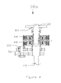
図4および図5は、図2および図3の変速装置の変形例18aを図示している。両方の実施形態に共通である構成要素には同じ参照符号が付けられている。変速装置18aには、副シャフト56と入力シャフト32との間にワンウェイクラッチ100が設けられている。これによって、どのギヤが選択されるかによって左右されるがワンウェイクラッチがつかむかあるいは解放するかのいずれかであるので、クラッチ切換に時間を要することなく滑らかなギヤシフトの利点がもたらされる。これの欠点は、後退ギヤが低速ギヤにおいてだけ操作することができることである。この実施形態では、制御システムは共通の槽/エンジンBUSあるいはCAN110に接続されている。
FIGS. 4 and 5 illustrate a
図6は、図1に示されたブラボー「型」駆動装置の代わりに、「アルファ」型駆動装置とともに使用するシステムを図示している。この場合において、出力シャフト24はベベルギヤ24および28を介して入力シャフト32へ直接接続されており、また、この駆動装置の下端には、ドッグクラッチ120あるいは類似物を介して選択されたプロペラ40に隣接して前進および後退ベベルギヤが設けられている。
FIG. 6 illustrates a system for use with an “alpha” type drive instead of the Bravo “type” drive shown in FIG. In this case, the
上で説明されたシステムには2つの湿式クラッチが組み入れられているが、乾式クラッチもまた湿式クラッチに取って代わることができる、ということは認識されるであろう。 It will be appreciated that although the system described above incorporates two wet clutches, a dry clutch can also replace a wet clutch.
図7は、海洋用変速装置のさらに別の実施形態、この場合は単一クラッチ自動手動型変速装置100を示している。先に説明した変速装置の場合と同じように、この変速装置もまた、船内/船外海洋用駆動装置の一部として示されている。
FIG. 7 shows yet another embodiment of a marine transmission, in this case a single clutch automatic
図示されていない船舶の出力シャフトは、ほぼ水平な軸の周りに回転するとともに、ベアリング103に取り付けられた変速装置の入力シャフト102と同軸であってこれを駆動させる。この海洋用変速装置の出力シャフト104は、ベアリング105に支持されており、また、入力シャフト102に対して平行であって入力シャフト102から間隔を置いて配置されている。
A marine output shaft (not shown) rotates about a substantially horizontal axis and is coaxial with and drives the
出力シャフト104の出力端部104aに画成されたベベルギヤ106は、前進および後退ベベルギヤ108,110にそれぞれ噛み合っており、また、ドッグクラッチ112(あるいは類似した装置)は、右ねじプロペラが嵌められているか左ねじプロペラが嵌められているかによって決まるが、垂直方向へ移動して垂直な出力シャフト114を後退ベベルギヤ110かあるいは前進ベベルギヤ108かのいずれかに接続するように、またはその逆となるように作用する。
The
この海洋用船舶のプロペラの、前進あるいは後退の方向の選択は、この海洋用変速装置の出力の後にドッグクラッチ112によって実行され、それゆえ、海洋用変速装置の入力シャフトおよび出力シャフトは、常に同じ向きに回転し、また、変速装置101は、入力シャフトあるいは出力シャフトを2つ以上の方向に回転させるように対処することを要求されない。
Selection of the forward or reverse direction of the marine vessel propeller is performed by the
当分野において標準であるように、図示されていない垂直な出力シャフトの下部が、垂直な出力シャフト114の垂直軸の移動をプロペラ駆動用水平シャフトのほぼ水平軸の移動に変換するさらに別の一対の噛み合いベベルギヤに作動可能に接続されている。
As is standard in the art, yet another pair of vertical output shaft lower portions, not shown, convert the vertical axis movement of the
第1ギヤのためのギヤホイール120が出力シャフト114に取り付けられ、これは次には、入力シャフト102に取り付けられたワンウェイクラッチを組み入れるギヤホイール122に噛み合っている。第2ギヤおよび関連クラッチ126のためのギヤホイール124が、第1ギヤに隣接する出力シャフトに、かつ、第1ギヤ120の、出力シャフトの出力端部104aとは反対側に取り付けられている。第2ギヤ124は、ワンウェイクラッチ122に隣接する入力シャフトに取り付けられたギヤホイール128に噛み合っている。
A
クラッチが係合しないときには、それは海洋用船舶がクラッチの故障の場合に第1ギヤで進むことができるような初期設定状態であるが、入力シャフトは、ドック入れおよび低速操作のために使用される第1ギヤ120を介して出力シャフトを駆動する。ギヤが回転すると、第1クラッチパックを横切って滑りが生じる。クラッチ126の主要部は出力シャフトとともに回転する。
When the clutch is not engaged, it is in an initial setting that allows the marine vessel to proceed with the first gear in case of clutch failure, but the input shaft is used for docking and low speed operation The output shaft is driven through the
クラッチ126が係合すると、第2ギヤが係合し、かつ、クラッチ126と第2ギヤとが出力シャフトとともに回る。第1ギヤ120は、第2ギヤ124と同じ速度、同じ角速度で回転させられ、また、ワンウェイクラッチ122はオーバーランする。
When the clutch 126 is engaged, the second gear is engaged, and the clutch 126 and the second gear rotate together with the output shaft. The
現行の海洋用変速装置とは対照的に、ギヤ比を2つのギヤホイールであるいは第1比および第2比の両方が変更される(第2比が通常は1:1であっても)ときには4つのギヤホイールで単に置き換えることによって変更することは比較的簡単な事柄である、ということは認識される。 In contrast to current marine transmissions, when the gear ratio is changed with two gear wheels or both the first ratio and the second ratio are changed (even if the second ratio is usually 1: 1) It will be appreciated that changing by simply replacing four gear wheels is a relatively simple matter.
さらに別の利点は、この駆動装置が、2つの相異なるギヤを提供するためにはただ1つのクラッチだけを必要とし、また、それゆえ、いっそうコンパクトであるということである。 Yet another advantage is that the drive requires only one clutch to provide two different gears and is therefore more compact.
この変速装置には、電子制御部130、油圧ポンプ132および先に説明された実施形態に関して説明されたものと同じ型のセンサーを含む制御システムが組み入れられている。
The transmission incorporates a control system that includes an
図8には、図7に示されているものに類似した構成が示されているが、ただし、この構成では、第1ギヤホイール104および第2ギヤホイール126の相対位置は入力シャフトおよび出力シャフトにおいて逆になっており、また、クラッチは出力シャフトの出力端部に隣接して位置決めされている。この構成には、全体の変速装置が上部でいっそう短くされており、図11を参照して以下でいっそう詳しく検討するように、変速装置がスイミングプラットフォームを取り除くことができるということを保証するのに役立つという利点がある。図8では、および、続いて記載される実施形態では、図7の実施形態と共通である構成要素には同じ参照符号が付けられている。
FIG. 8 shows a configuration similar to that shown in FIG. 7, except that in this configuration, the relative positions of the
図9および図10は、2つのクラッチが組み入れられている海洋用2速度変速装置を示している。図9に示されたように、入力シャフト150はこれもまた、出力シャフト152に対して平行にかつ出力シャフト152から間隔を置いて配置され、出力シャフトの出力端部152aはこれもまた、図7および図8の構成について説明されたものに類似した構成で、垂直な軸を介して船のプロペラを駆動するためのベベルギヤおよびドッグクラッチ構成に接続されている。
9 and 10 show a marine two-speed transmission that incorporates two clutches. As shown in FIG. 9, the
入力シャフト150は、第1ギヤ154および第2ギヤ156を介して出力シャフト152に接続されている。第1ギヤは、ワンウェイクラッチを含むギヤホイール158に噛み合っている。第2ギヤ156は、ギヤホイール160に噛み合っている。摩擦クラッチ162および164が、第2ギヤおよび第1ギヤにそれぞれ係合するために設けられている。
The
第2ギヤがクラッチ162を使用することで係合されると、ワンウェイクラッチがオーバーランし、第1ギヤ154はそのまま回転する。第2ギヤでは、第1ギヤとこの第1ギヤに関連したクラッチとは、たいていの時間に使用されるギヤである第2ギヤにおける抗力がないように回転することはない。
When the second gear is engaged by using the clutch 162, the one-way clutch overruns and the
この構成によれば、摩擦クラッチを制御するために電子空気圧ソレノイドあるいは電子油圧ソレノイドを使用することで、図1〜図6に示された実施形態に関連して上で説明されたような現行の海洋用駆動装置に勝るいくつかの利点が提供される。この構成は、前進および後退の選択が出力シャフトの端部152aの後で行われるため、逆回転感知性のものではない。
According to this configuration, the use of an electropneumatic solenoid or electrohydraulic solenoid to control the friction clutch allows the current one as described above in connection with the embodiment shown in FIGS. Several advantages are provided over marine drives. This arrangement is not sensitive to reverse rotation because the forward and backward selection is made after the
代わりの構成が図10に示されている。この型のものでは、2つのクラッチパックが、ギヤと出力シャフトの出力部との間において、ギヤの反対側に位置決めされている。図10の構成と比べると、図9は最上部でいっそう短いものである。この構成によれば、全体の変速装置が最上部でいっそう短くなる。船尾駆動装置が使用されないときには、それは水の外へ上げられるが、その駆動装置がきれいにしなければならないスイミングプラットフォームが存在する。この設計は、最上部の軸でいっそう短くて、スイミングプラットフォームをきれいにするための多くの部屋が可能になる。図11へ移ると、変速およびプロペラアセンブリー200は、このアセンブリーを矢印Aで表したように時計回り方向へ回転させることによって、水の外へ引き上げることができる。アセンブリー200の最上部202はこの船の後部へ向かって移動し、後部204はスイミングプラットフォーム206へ向かって移動する。この変速装置が短ければ短いほど、それがスイミングプラットフォームにぶつかるおそれはより少ない。
An alternative configuration is shown in FIG. In this type, two clutch packs are positioned on opposite sides of the gear between the gear and the output portion of the output shaft. Compared to the configuration of FIG. 10, FIG. 9 is even shorter at the top. According to this configuration, the entire transmission is further shortened at the top. When the stern drive is not in use, it is raised out of the water, but there are swimming platforms that the drive must clean. This design is much shorter on the top axis, allowing many rooms to clean the swimming platform. Turning to FIG. 11, the transmission and
また、ワンウェイクラッチは、入力シャフトにおける噛み合い用ギヤホイール158にではなく出力シャフトにおける第1ギヤ154に設けられている。この構成では、出力シャフトは第2ギヤ比でより速く回転し、その後に、ワンウェイクラッチが第1ギヤ比の異なる速度でオーバーランする。
The one-way clutch is provided not on the
さらに、このシステムは、船内/船外海洋用推進システムの船尾駆動ユニットに組み入れられて説明されているが、このシステムはエンジンおよび変速装置システムがそのコンパクトな寸法と軽い重量とに起因して船尾梁の後方にすべて位置決めされている船外機付きボートシステムに組み入れることもできる、ということは認識される。このシステムは、エンジンとプロペラとの間におけるシャフト駆動、v駆動、ジェット駆動および表面駆動の海洋用推進システムの変形例にもまた使用することができる。 In addition, the system is described incorporated into the stern drive unit of an inboard / outboard marine propulsion system, but the system is stern due to the compact size and light weight of the engine and transmission system. It will be appreciated that it can also be incorporated into an outboard boat system that is all positioned behind the beam. This system can also be used for variations of shaft driven, v driven, jet driven and surface driven marine propulsion systems between the engine and propeller.
この変速装置は、フォークリフトまたは工業用変速装置のような、寸法、コストおよび重量が課題である非海洋用途に使用することもできる。 This transmission can also be used in non-marine applications where size, cost and weight are issues, such as forklifts or industrial transmissions.
広く説明されたように本発明の精神あるいは範囲から逸脱することなく特定の実施形態に関して多数の変更および/または修正を本発明に行うことができるということは、当業者に明らかである。これらの実施形態はそれゆえ、すべての点で例示的なものであって限定的なものではないとみなされる。 It will be apparent to those skilled in the art that numerous changes and / or modifications can be made to the invention with respect to particular embodiments without departing from the spirit or scope of the invention as broadly described. These embodiments are therefore considered in all respects as illustrative and not restrictive.
Claims (15)
入力シャフトと、
出力シャフトと、
第1ギヤにおける前記出力シャフトを駆動するために前記入力シャフトを前記出力シャフトに接続する第1ギヤトレインと、
第2ギヤにおける前記出力シャフトを駆動するために前記入力シャフトを前記出力シャフトに接続する第2ギヤトレインと、
前記入力シャフトを前記出力シャフトに1対1以外のギヤ比で接続するためのクラッチ手段と、
を備える2速度変速装置システム。 A two-speed transmission system for a marine vessel,
An input shaft;
An output shaft;
A first gear train connecting the input shaft to the output shaft to drive the output shaft in a first gear;
A second gear train connecting the input shaft to the output shaft to drive the output shaft in a second gear;
Clutch means for connecting the input shaft to the output shaft at a gear ratio other than 1: 1;
A two-speed transmission system comprising:
典型的には前記入力シャフトおよび前記出力シャフトに対して平行に配置された副シャフトと、
前記副シャフトを前記入力シャフトを介して駆動するために前記入力シャフトを前記副シャフトに接続する第1ギヤトレインと、
前記副シャフトを前記出力シャフトに接続する第2ギヤトレインと、
を含んでおり、
前記第1クラッチ手段は、前記入力シャフトを前記出力シャフトに接続し、かつ、
前記第2クラッチ手段は、前記副シャフトを介して前記入力シャフトを前記出力シャフトに接続して1対1以外のギヤ比を与える、2速度変速装置システム。 First clutch means for connecting the input shaft to the coaxial output shaft;
A secondary shaft typically disposed parallel to the input shaft and the output shaft;
A first gear train connecting the input shaft to the secondary shaft to drive the secondary shaft through the input shaft;
A second gear train connecting the secondary shaft to the output shaft;
Contains
The first clutch means connects the input shaft to the output shaft; and
The second clutch means is a two-speed transmission system that provides a gear ratio other than 1: 1 by connecting the input shaft to the output shaft via the auxiliary shaft.
Applications Claiming Priority (4)
| Application Number | Priority Date | Filing Date | Title |
|---|---|---|---|
| AU2003903771A AU2003903771A0 (en) | 2003-07-21 | 2003-07-21 | Dual clutch transmission |
| US50694703P | 2003-09-28 | 2003-09-28 | |
| AU2004901167A AU2004901167A0 (en) | 2004-03-05 | Transmission for marine craft | |
| PCT/AU2004/000973 WO2005007503A1 (en) | 2003-07-21 | 2004-07-20 | Dual speed transmission |
Related Child Applications (1)
| Application Number | Title | Priority Date | Filing Date |
|---|---|---|---|
| JP2012034469A Division JP2012162256A (en) | 2003-07-21 | 2012-02-20 | Dual speed transmission |
Publications (2)
| Publication Number | Publication Date |
|---|---|
| JP2006528100A true JP2006528100A (en) | 2006-12-14 |
| JP2006528100A5 JP2006528100A5 (en) | 2007-09-06 |
Family
ID=46045488
Family Applications (2)
| Application Number | Title | Priority Date | Filing Date |
|---|---|---|---|
| JP2006520631A Pending JP2006528100A (en) | 2003-07-21 | 2004-07-20 | Multi-speed transmission |
| JP2012034469A Pending JP2012162256A (en) | 2003-07-21 | 2012-02-20 | Dual speed transmission |
Family Applications After (1)
| Application Number | Title | Priority Date | Filing Date |
|---|---|---|---|
| JP2012034469A Pending JP2012162256A (en) | 2003-07-21 | 2012-02-20 | Dual speed transmission |
Country Status (8)
| Country | Link |
|---|---|
| US (1) | US7891263B2 (en) |
| EP (1) | EP1651513A4 (en) |
| JP (2) | JP2006528100A (en) |
| KR (1) | KR20060111901A (en) |
| AU (1) | AU2004257892B2 (en) |
| CA (1) | CA2533185A1 (en) |
| NZ (1) | NZ544870A (en) |
| WO (1) | WO2005007503A1 (en) |
Cited By (12)
| Publication number | Priority date | Publication date | Assignee | Title |
|---|---|---|---|---|
| JP2009538765A (en) * | 2006-06-01 | 2009-11-12 | イェーゲル フランツペーター | Ship drive |
| WO2010041531A1 (en) * | 2008-10-06 | 2010-04-15 | Ntn株式会社 | Electric motor driving device |
| JP2010090947A (en) * | 2008-10-06 | 2010-04-22 | Ntn Corp | Electric motor driving device |
| KR101313585B1 (en) * | 2011-06-13 | 2013-10-01 | 삼성중공업 주식회사 | Propulsion apparatus for ship, and ship having the same |
| KR101313611B1 (en) * | 2011-06-07 | 2013-10-02 | 삼성중공업 주식회사 | Propulsion apparatus for ship, and ship having the same |
| KR101380660B1 (en) * | 2011-06-07 | 2014-04-04 | 삼성중공업 주식회사 | Propulsion apparatus for ship, and ship having the same |
| KR101390843B1 (en) * | 2012-04-27 | 2014-05-08 | 삼성중공업 주식회사 | Propulsion apparatus for ship, and ship having the same |
| KR101399852B1 (en) * | 2012-04-27 | 2014-05-28 | 삼성중공업 주식회사 | Propulsion apparatus for ship, and ship having the same |
| KR101399855B1 (en) | 2012-05-08 | 2014-05-28 | 삼성중공업 주식회사 | Propulsion apparatus for ship, and ship having the same |
| KR101444328B1 (en) * | 2012-04-27 | 2014-09-26 | 삼성중공업 주식회사 | Propulsion apparatus for ship, and ship having the same |
| KR101444331B1 (en) | 2012-05-09 | 2014-09-30 | 삼성중공업 주식회사 | Propulsion apparatus for ship, and ship having the same |
| JP2020514177A (en) * | 2016-12-19 | 2020-05-21 | ロバート ジョージ エバンズRobert George EVANS | Transmission assembly |
Families Citing this family (38)
| Publication number | Priority date | Publication date | Assignee | Title |
|---|---|---|---|---|
| JP4979556B2 (en) | 2007-12-04 | 2012-07-18 | ヤンマー株式会社 | Hydraulic control device for marine speed reducer |
| KR101139184B1 (en) * | 2007-12-27 | 2012-04-26 | 아이신에이더블류 가부시키가이샤 | Controller of automatic shift |
| JP2009185972A (en) * | 2008-02-08 | 2009-08-20 | Yamaha Motor Co Ltd | Outboard motor |
| DE102008018703A1 (en) * | 2008-04-10 | 2009-10-15 | Reintjes Gmbh | Marine gear |
| EP2143979B1 (en) * | 2008-05-13 | 2012-02-08 | Magneti Marelli S.p.A. | Double-clutch gearchange |
| DE102008042702A1 (en) * | 2008-10-09 | 2010-04-15 | Zf Friedrichshafen Ag | Propeller drive arrangement for controlling and driving a ship |
| JP5303318B2 (en) * | 2009-03-06 | 2013-10-02 | 株式会社エフ・シー・シー | Power transmission device |
| DE102009003107A1 (en) * | 2009-05-14 | 2010-11-18 | Zf Friedrichshafen Ag | Drive arrangement for a motor vehicle with a power take-off clutch |
| CN101813168B (en) * | 2010-04-30 | 2013-03-27 | 沃德(天津)传动有限公司 | Dual-speed-ratio speed reducer |
| JP5855843B2 (en) * | 2011-04-20 | 2016-02-09 | Gknドライブラインジャパン株式会社 | Drive device |
| WO2013138942A1 (en) | 2012-03-23 | 2013-09-26 | Pacific Rim Engineered Products (1987) Ltd. | Gear engagement mechanism for transmissions and related methods |
| CA2866935A1 (en) | 2012-03-23 | 2013-09-26 | Pacific Rim Engineered Products (1987) Ltd. | Dual clutch type power transmission with alternative torque transmission path providing alternative ratios |
| CN103523194A (en) * | 2013-10-29 | 2014-01-22 | 中国船舶重工集团公司第七�三研究所 | Double-speed gear transmission |
| US20150158572A1 (en) * | 2013-12-10 | 2015-06-11 | Caterpillar Inc. | Transmission system for pod system of marine vessel |
| NL2012904B1 (en) * | 2014-05-28 | 2016-06-08 | Ihc Holland Ie Bv | Gearbox for a dredging vessel. |
| KR101601472B1 (en) * | 2014-08-22 | 2016-03-09 | 현대자동차주식회사 | Transmission for electric vehicle |
| US9446829B1 (en) | 2014-12-22 | 2016-09-20 | Brunswick Corporation | Transmissions for outboard marine engines having internal ring gear and layshaft |
| US9676463B1 (en) | 2014-12-30 | 2017-06-13 | Brunswick Corporation | Planetary transmission arrangements for marine propulsion devices |
| US10124874B1 (en) | 2015-01-26 | 2018-11-13 | Brunswick Corporation | Systems and methods for controlling planetary transmission arrangements for marine propulsion devices |
| US10215278B1 (en) | 2015-02-20 | 2019-02-26 | Brunswick Corporation | Shift system for a marine drive |
| US9731804B1 (en) | 2015-02-20 | 2017-08-15 | Brunswick Corporation | Directly mounted shaft actuator |
| US9896177B1 (en) | 2015-02-20 | 2018-02-20 | Brunswick Corporation | Shift system for a marine drive |
| US9441724B1 (en) | 2015-04-06 | 2016-09-13 | Brunswick Corporation | Method and system for monitoring and controlling a transmission |
| US9759321B1 (en) | 2015-04-08 | 2017-09-12 | Brunswick Corporation | Band brake actuators for actuating band brakes on planetary gearsets in marine propulsion devices |
| CN105676756B (en) * | 2015-08-19 | 2018-02-23 | 张桂臣 | Full circle swinging machine oar rudder monitoring combination system and monitoring method |
| US10161482B1 (en) | 2016-12-08 | 2018-12-25 | Brunswick Corporation | Planetary transmission arrangements for marine propulsion devices |
| TWI644041B (en) | 2017-10-20 | 2018-12-11 | 財團法人工業技術研究院 | Dual axes clutch variable speed apparatus |
| TWI641772B (en) | 2017-10-20 | 2018-11-21 | 財團法人工業技術研究院 | Dual axes toggling variable speed apparatus |
| DE102018204474A1 (en) * | 2018-03-23 | 2019-09-26 | Zf Friedrichshafen Ag | Transmission for a marine propulsion and marine propulsion |
| CN108438188A (en) * | 2018-03-30 | 2018-08-24 | 莆田三帆设备制造有限公司 | A kind of outboard tail machine that split type 360 degree of variable-ratio freely turns to |
| US11215128B1 (en) * | 2018-08-14 | 2022-01-04 | Brunswick Corporation | Acceleration control method for marine engine |
| US10766592B1 (en) | 2018-08-28 | 2020-09-08 | Brunswick Corporation | System and method for controlling a multi-speed transmission on a marine engine |
| US10794474B1 (en) | 2018-10-25 | 2020-10-06 | Brunswick Corporation | System and method for controlling a transmission on a marine engine |
| CN109654177B (en) * | 2018-11-30 | 2023-10-13 | 浙江云洲科技有限公司 | Flexible steering stepless gearbox for hydraulic control |
| DE102020202788B3 (en) * | 2020-03-04 | 2021-04-01 | Magna Pt B.V. & Co. Kg | Drive train for a vehicle and a method for operating a drive train with a two-speed transmission |
| US11254402B1 (en) * | 2020-11-02 | 2022-02-22 | Brunswick Corporation | Method and system for automated launch control of a marine vessel |
| KR102357889B1 (en) * | 2020-12-07 | 2022-02-07 | (주)한국알앤드디 | Heat dissipation device of engine room for horizontally mounted outboard unit |
| WO2023102241A1 (en) * | 2021-12-03 | 2023-06-08 | Omni Powertrain Technologies, Llc | Two speed gearbox |
Citations (9)
| Publication number | Priority date | Publication date | Assignee | Title |
|---|---|---|---|---|
| JPS54124873U (en) * | 1978-02-20 | 1979-08-31 | ||
| JPS5938195A (en) * | 1982-08-25 | 1984-03-01 | Yanmar Diesel Engine Co Ltd | Lubricating oil racing pump for vessel |
| JPS6175529U (en) * | 1984-10-23 | 1986-05-21 | ||
| JPH0198744A (en) * | 1987-10-06 | 1989-04-17 | Yanmar Diesel Engine Co Ltd | Hydraulic control device for marine speed reducing reversing gear |
| JPH03295792A (en) * | 1990-04-13 | 1991-12-26 | Yanmar Diesel Engine Co Ltd | Marine reduction/reverse gear |
| JP2001141742A (en) * | 1999-11-18 | 2001-05-25 | Kanzaki Kokyukoki Mfg Co Ltd | Angular acceleration detector, and trolling control device and speed change control device for agricultural working vehicle using it |
| JP2001200899A (en) * | 1999-12-16 | 2001-07-27 | Luk Lamellen & Kupplungsbau Gmbh | Transmission and method for operating the transmission |
| JP2002048199A (en) * | 2000-08-02 | 2002-02-15 | Yanmar Diesel Engine Co Ltd | Speed change mechanism and speed change controlling method for marine propelling apparatus |
| GB2367598A (en) * | 2000-10-04 | 2002-04-10 | Combined Engineering Concepts | A drive transmission for a stern or outboard drive of a watercraft |
Family Cites Families (21)
| Publication number | Priority date | Publication date | Assignee | Title |
|---|---|---|---|---|
| GB596307A (en) | 1945-01-11 | 1948-01-01 | Shadwell Harry Grylls | Improvements in or relating to change-speed gears |
| US1701403A (en) * | 1924-12-20 | 1929-02-05 | Thomas C Coykendall | System of marine propulsion |
| US1795135A (en) * | 1929-03-04 | 1931-03-03 | Zahnradfabrik Ag | Gear |
| GB1241744A (en) | 1969-01-13 | 1971-08-04 | Steyr Daimler Puch Ag | A transmission for agricultural tractors |
| US4323354A (en) * | 1979-02-15 | 1982-04-06 | Outboard Marine Corporation | Two-speed automatic transmission for a marine propulsion device |
| US4331432A (en) * | 1979-11-08 | 1982-05-25 | Outboard Marine Corporation | Hydraulically actuated two-speed transmission for a marine propulsion device |
| JPS60126732U (en) * | 1984-02-03 | 1985-08-26 | ヤマハ発動機株式会社 | Drive clutch for small ships |
| JPS62191297A (en) * | 1986-02-17 | 1987-08-21 | Honda Motor Co Ltd | Outboard machine |
| FI76034C (en) * | 1986-03-10 | 1988-09-09 | Rauma Repola Oy | KOPPLING FOER SKYDDNING AV MEKANISM. |
| GB2205366A (en) | 1987-06-02 | 1988-12-07 | Ricardo Consulting Eng | Automatic gearboxes having centrifugal clutches |
| US4966267A (en) * | 1989-09-21 | 1990-10-30 | Borg-Warner Automotive Diversified Transmission Products Corporation | Ball screw actuated clutch combination |
| DE4031571A1 (en) * | 1990-10-05 | 1992-04-09 | Daimler Benz Ag | METHOD FOR SHIFTING A MULTIPLE-WAY GEAR GEAR WITH ANY GEAR BY A GEAR CLUTCH WITH YOUR SHAFT COUPLABLE LOCKING WHEELS |
| US5085302A (en) * | 1990-12-18 | 1992-02-04 | The Falk Corporation | Marine reverse reduction gearbox |
| AU661697B2 (en) | 1992-07-02 | 1995-08-03 | Tai-Her Yang | An automatic transmission for accommodating variable loads |
| JP2943610B2 (en) * | 1994-06-24 | 1999-08-30 | トヨタ自動車株式会社 | Transmission control device for vehicle transmission |
| US5494466A (en) * | 1995-01-31 | 1996-02-27 | Vernea; Stefan | Transmission for dual propellers driven by an inboard marine engine |
| EP1013966B1 (en) * | 1998-12-24 | 2002-09-25 | DaimlerChrysler AG | Toothed speed-changing gearing with two parallel transmission paths |
| WO2001061212A1 (en) * | 2000-02-15 | 2001-08-23 | Luk Lamellen Und Kupplungsbau Beteiligungs Kg | Torque transmission device, in particular with double clutch drive mechanism |
| US6350165B1 (en) | 2000-06-21 | 2002-02-26 | Bombardier Motor Corporation Of America | Marine stern drive two-speed transmission |
| JP2002276797A (en) * | 2001-03-15 | 2002-09-25 | Hitachi Ltd | Automatic transmission |
| JP3502058B2 (en) * | 2001-04-16 | 2004-03-02 | 富士重工業株式会社 | Automatic transmission |
-
2004
- 2004-07-20 WO PCT/AU2004/000973 patent/WO2005007503A1/en active Application Filing
- 2004-07-20 EP EP04737593A patent/EP1651513A4/en not_active Withdrawn
- 2004-07-20 NZ NZ544870A patent/NZ544870A/en unknown
- 2004-07-20 CA CA002533185A patent/CA2533185A1/en not_active Abandoned
- 2004-07-20 KR KR1020067001414A patent/KR20060111901A/en not_active Application Discontinuation
- 2004-07-20 JP JP2006520631A patent/JP2006528100A/en active Pending
- 2004-07-20 AU AU2004257892A patent/AU2004257892B2/en not_active Ceased
- 2004-07-20 US US10/565,474 patent/US7891263B2/en not_active Expired - Fee Related
-
2012
- 2012-02-20 JP JP2012034469A patent/JP2012162256A/en active Pending
Patent Citations (9)
| Publication number | Priority date | Publication date | Assignee | Title |
|---|---|---|---|---|
| JPS54124873U (en) * | 1978-02-20 | 1979-08-31 | ||
| JPS5938195A (en) * | 1982-08-25 | 1984-03-01 | Yanmar Diesel Engine Co Ltd | Lubricating oil racing pump for vessel |
| JPS6175529U (en) * | 1984-10-23 | 1986-05-21 | ||
| JPH0198744A (en) * | 1987-10-06 | 1989-04-17 | Yanmar Diesel Engine Co Ltd | Hydraulic control device for marine speed reducing reversing gear |
| JPH03295792A (en) * | 1990-04-13 | 1991-12-26 | Yanmar Diesel Engine Co Ltd | Marine reduction/reverse gear |
| JP2001141742A (en) * | 1999-11-18 | 2001-05-25 | Kanzaki Kokyukoki Mfg Co Ltd | Angular acceleration detector, and trolling control device and speed change control device for agricultural working vehicle using it |
| JP2001200899A (en) * | 1999-12-16 | 2001-07-27 | Luk Lamellen & Kupplungsbau Gmbh | Transmission and method for operating the transmission |
| JP2002048199A (en) * | 2000-08-02 | 2002-02-15 | Yanmar Diesel Engine Co Ltd | Speed change mechanism and speed change controlling method for marine propelling apparatus |
| GB2367598A (en) * | 2000-10-04 | 2002-04-10 | Combined Engineering Concepts | A drive transmission for a stern or outboard drive of a watercraft |
Cited By (14)
| Publication number | Priority date | Publication date | Assignee | Title |
|---|---|---|---|---|
| JP2009538765A (en) * | 2006-06-01 | 2009-11-12 | イェーゲル フランツペーター | Ship drive |
| WO2010041531A1 (en) * | 2008-10-06 | 2010-04-15 | Ntn株式会社 | Electric motor driving device |
| JP2010090947A (en) * | 2008-10-06 | 2010-04-22 | Ntn Corp | Electric motor driving device |
| CN102171486A (en) * | 2008-10-06 | 2011-08-31 | Ntn株式会社 | Electric motor driving device |
| US8441161B2 (en) | 2008-10-06 | 2013-05-14 | Ntn Corporation | Electric motor drive device |
| KR101313611B1 (en) * | 2011-06-07 | 2013-10-02 | 삼성중공업 주식회사 | Propulsion apparatus for ship, and ship having the same |
| KR101380660B1 (en) * | 2011-06-07 | 2014-04-04 | 삼성중공업 주식회사 | Propulsion apparatus for ship, and ship having the same |
| KR101313585B1 (en) * | 2011-06-13 | 2013-10-01 | 삼성중공업 주식회사 | Propulsion apparatus for ship, and ship having the same |
| KR101390843B1 (en) * | 2012-04-27 | 2014-05-08 | 삼성중공업 주식회사 | Propulsion apparatus for ship, and ship having the same |
| KR101399852B1 (en) * | 2012-04-27 | 2014-05-28 | 삼성중공업 주식회사 | Propulsion apparatus for ship, and ship having the same |
| KR101444328B1 (en) * | 2012-04-27 | 2014-09-26 | 삼성중공업 주식회사 | Propulsion apparatus for ship, and ship having the same |
| KR101399855B1 (en) | 2012-05-08 | 2014-05-28 | 삼성중공업 주식회사 | Propulsion apparatus for ship, and ship having the same |
| KR101444331B1 (en) | 2012-05-09 | 2014-09-30 | 삼성중공업 주식회사 | Propulsion apparatus for ship, and ship having the same |
| JP2020514177A (en) * | 2016-12-19 | 2020-05-21 | ロバート ジョージ エバンズRobert George EVANS | Transmission assembly |
Also Published As
| Publication number | Publication date |
|---|---|
| JP2012162256A (en) | 2012-08-30 |
| NZ544870A (en) | 2007-12-21 |
| CA2533185A1 (en) | 2005-01-27 |
| KR20060111901A (en) | 2006-10-30 |
| EP1651513A4 (en) | 2008-09-03 |
| WO2005007503A1 (en) | 2005-01-27 |
| AU2004257892B2 (en) | 2011-05-19 |
| AU2004257892A1 (en) | 2005-01-27 |
| EP1651513A1 (en) | 2006-05-03 |
| US20070180941A1 (en) | 2007-08-09 |
| US7891263B2 (en) | 2011-02-22 |
Similar Documents
| Publication | Publication Date | Title |
|---|---|---|
| JP2006528100A (en) | Multi-speed transmission | |
| JP2006528100A5 (en) | ||
| US7685899B2 (en) | Single clutch transmission | |
| JP2006528310A5 (en) | ||
| US5711742A (en) | Multi-speed marine propulsion system with automatic shifting mechanism | |
| US20080045093A1 (en) | De-Coupling Clutch, Particularly for Marine Use | |
| US9676463B1 (en) | Planetary transmission arrangements for marine propulsion devices | |
| US5494466A (en) | Transmission for dual propellers driven by an inboard marine engine | |
| JP2014512302A5 (en) | ||
| US9446829B1 (en) | Transmissions for outboard marine engines having internal ring gear and layshaft | |
| JP5623155B2 (en) | Counter-rotating propeller propulsion device | |
| US10696370B1 (en) | Systems and methods for controlling planetary transmission arrangements for marine propulsion devices | |
| AU2018378801B2 (en) | Outboard-motor automatic disengaging clutch system and method | |
| JP2009538765A (en) | Ship drive | |
| JP2007509292A (en) | Decoupling clutch especially for ships | |
| US11459076B1 (en) | Systems and methods for controlling transmission valves in a marine propulsion device | |
| US11215128B1 (en) | Acceleration control method for marine engine | |
| CN1842462A (en) | Single clutch transmission | |
| AU2004281855A1 (en) | Decoupling clutch, particularly for marine use |
Legal Events
| Date | Code | Title | Description |
|---|---|---|---|
| A521 | Written amendment |
Free format text: JAPANESE INTERMEDIATE CODE: A523 Effective date: 20070720 |
|
| A621 | Written request for application examination |
Free format text: JAPANESE INTERMEDIATE CODE: A621 Effective date: 20070720 |
|
| A977 | Report on retrieval |
Free format text: JAPANESE INTERMEDIATE CODE: A971007 Effective date: 20091027 |
|
| A131 | Notification of reasons for refusal |
Free format text: JAPANESE INTERMEDIATE CODE: A131 Effective date: 20091104 |
|
| A601 | Written request for extension of time |
Free format text: JAPANESE INTERMEDIATE CODE: A601 Effective date: 20100204 |
|
| A602 | Written permission of extension of time |
Free format text: JAPANESE INTERMEDIATE CODE: A602 Effective date: 20100212 |
|
| A601 | Written request for extension of time |
Free format text: JAPANESE INTERMEDIATE CODE: A601 Effective date: 20100302 |
|
| A602 | Written permission of extension of time |
Free format text: JAPANESE INTERMEDIATE CODE: A602 Effective date: 20100309 |
|
| A521 | Written amendment |
Free format text: JAPANESE INTERMEDIATE CODE: A523 Effective date: 20100506 |
|
| A131 | Notification of reasons for refusal |
Free format text: JAPANESE INTERMEDIATE CODE: A131 Effective date: 20101207 |
|
| A601 | Written request for extension of time |
Free format text: JAPANESE INTERMEDIATE CODE: A601 Effective date: 20110307 |
|
| A602 | Written permission of extension of time |
Free format text: JAPANESE INTERMEDIATE CODE: A602 Effective date: 20110314 |
|
| A601 | Written request for extension of time |
Free format text: JAPANESE INTERMEDIATE CODE: A601 Effective date: 20110407 |
|
| A602 | Written permission of extension of time |
Free format text: JAPANESE INTERMEDIATE CODE: A602 Effective date: 20110414 |
|
| A521 | Written amendment |
Free format text: JAPANESE INTERMEDIATE CODE: A523 Effective date: 20110509 |
|
| A02 | Decision of refusal |
Free format text: JAPANESE INTERMEDIATE CODE: A02 Effective date: 20111018 |
|
| A711 | Notification of change in applicant |
Free format text: JAPANESE INTERMEDIATE CODE: A711 Effective date: 20111101 |
|
| A521 | Written amendment |
Free format text: JAPANESE INTERMEDIATE CODE: A821 Effective date: 20111101 |
|
| A521 | Written amendment |
Free format text: JAPANESE INTERMEDIATE CODE: A523 Effective date: 20120220 |
|
| A911 | Transfer to examiner for re-examination before appeal (zenchi) |
Free format text: JAPANESE INTERMEDIATE CODE: A911 Effective date: 20120409 |
|
| A912 | Re-examination (zenchi) completed and case transferred to appeal board |
Free format text: JAPANESE INTERMEDIATE CODE: A912 Effective date: 20120615 |