KR101139184B1 - Controller of automatic shift - Google Patents
Controller of automatic shift Download PDFInfo
- Publication number
- KR101139184B1 KR101139184B1 KR1020107002532A KR20107002532A KR101139184B1 KR 101139184 B1 KR101139184 B1 KR 101139184B1 KR 1020107002532 A KR1020107002532 A KR 1020107002532A KR 20107002532 A KR20107002532 A KR 20107002532A KR 101139184 B1 KR101139184 B1 KR 101139184B1
- Authority
- KR
- South Korea
- Prior art keywords
- pressure
- clutch
- brake
- input
- torque
- Prior art date
Links
Images


Classifications
-
- F—MECHANICAL ENGINEERING; LIGHTING; HEATING; WEAPONS; BLASTING
- F16—ENGINEERING ELEMENTS AND UNITS; GENERAL MEASURES FOR PRODUCING AND MAINTAINING EFFECTIVE FUNCTIONING OF MACHINES OR INSTALLATIONS; THERMAL INSULATION IN GENERAL
- F16H—GEARING
- F16H61/00—Control functions within control units of change-speed- or reversing-gearings for conveying rotary motion ; Control of exclusively fluid gearing, friction gearing, gearings with endless flexible members or other particular types of gearing
- F16H61/12—Detecting malfunction or potential malfunction, e.g. fail safe; Circumventing or fixing failures
- F16H2061/1204—Detecting malfunction or potential malfunction, e.g. fail safe; Circumventing or fixing failures for malfunction caused by simultaneous engagement of different ratios resulting in transmission lock state or tie-up condition
-
- F—MECHANICAL ENGINEERING; LIGHTING; HEATING; WEAPONS; BLASTING
- F16—ENGINEERING ELEMENTS AND UNITS; GENERAL MEASURES FOR PRODUCING AND MAINTAINING EFFECTIVE FUNCTIONING OF MACHINES OR INSTALLATIONS; THERMAL INSULATION IN GENERAL
- F16H—GEARING
- F16H61/00—Control functions within control units of change-speed- or reversing-gearings for conveying rotary motion ; Control of exclusively fluid gearing, friction gearing, gearings with endless flexible members or other particular types of gearing
- F16H61/12—Detecting malfunction or potential malfunction, e.g. fail safe; Circumventing or fixing failures
- F16H2061/1224—Adapting to failures or work around with other constraints, e.g. circumvention by avoiding use of failed parts
-
- F—MECHANICAL ENGINEERING; LIGHTING; HEATING; WEAPONS; BLASTING
- F16—ENGINEERING ELEMENTS AND UNITS; GENERAL MEASURES FOR PRODUCING AND MAINTAINING EFFECTIVE FUNCTIONING OF MACHINES OR INSTALLATIONS; THERMAL INSULATION IN GENERAL
- F16H—GEARING
- F16H61/00—Control functions within control units of change-speed- or reversing-gearings for conveying rotary motion ; Control of exclusively fluid gearing, friction gearing, gearings with endless flexible members or other particular types of gearing
- F16H61/12—Detecting malfunction or potential malfunction, e.g. fail safe; Circumventing or fixing failures
- F16H2061/1256—Detecting malfunction or potential malfunction, e.g. fail safe; Circumventing or fixing failures characterised by the parts or units where malfunctioning was assumed or detected
- F16H2061/126—Detecting malfunction or potential malfunction, e.g. fail safe; Circumventing or fixing failures characterised by the parts or units where malfunctioning was assumed or detected the failing part is the controller
- F16H2061/1264—Hydraulic parts of the controller, e.g. a sticking valve or clogged channel
-
- F—MECHANICAL ENGINEERING; LIGHTING; HEATING; WEAPONS; BLASTING
- F16—ENGINEERING ELEMENTS AND UNITS; GENERAL MEASURES FOR PRODUCING AND MAINTAINING EFFECTIVE FUNCTIONING OF MACHINES OR INSTALLATIONS; THERMAL INSULATION IN GENERAL
- F16H—GEARING
- F16H61/00—Control functions within control units of change-speed- or reversing-gearings for conveying rotary motion ; Control of exclusively fluid gearing, friction gearing, gearings with endless flexible members or other particular types of gearing
- F16H61/68—Control functions within control units of change-speed- or reversing-gearings for conveying rotary motion ; Control of exclusively fluid gearing, friction gearing, gearings with endless flexible members or other particular types of gearing specially adapted for stepped gearings
- F16H61/684—Control functions within control units of change-speed- or reversing-gearings for conveying rotary motion ; Control of exclusively fluid gearing, friction gearing, gearings with endless flexible members or other particular types of gearing specially adapted for stepped gearings without interruption of drive
- F16H61/686—Control functions within control units of change-speed- or reversing-gearings for conveying rotary motion ; Control of exclusively fluid gearing, friction gearing, gearings with endless flexible members or other particular types of gearing specially adapted for stepped gearings without interruption of drive with orbital gears
Abstract
정상시 유압 설정 수단(72)은, 입력 토크와 토크 분담에 기초하여, 각 변속단에서 결합되는 2개의 마찰 결합 요소에 있어서의 전달 토크를 산출하고, 그들의 유압 서보에 각각 공급하는 결합압을 설정한다. 이 설정된 결합압은, 그들 2개의 마찰 결합 요소에 슬립이 발생하지 않고, 또한 해방 중인 다른 마찰 결합 요소의 유압 서보에 라인압이 공급되어 3개의 마찰 결합 요소가 동시 결합되었다고 해도, 토크 분담이 변경됨으로써, 3개 중 1개의 마찰 결합 요소가 차량의 관성력에 의해 슬립되도록 설정되어 있다. 3개의 마찰 결합 요소가 동시 결합되어도, 그 중 1개의 마찰 결합 요소가 슬립되므로, 컷오프 밸브를 이용하는 일 없이 주행 상태를 확보할 수 있어, 콤팩트화, 경량화, 비용 절감이 가능해진다.The normal hydraulic pressure setting means 72 calculates the transmission torques in the two frictional engagement elements coupled at each shift stage based on the input torque and the torque sharing, and sets the coupling pressures to be supplied to their hydraulic servos, respectively. do. Even if the set engagement pressure does not cause slippage between the two friction engagement elements, and the line pressure is supplied to the hydraulic servos of the other friction engagement elements being released, the torque sharing is changed even when the three friction engagement elements are simultaneously engaged. Thus, one of the three friction engagement elements is set to slip by the inertial force of the vehicle. Even when three friction engagement elements are engaged at the same time, one friction engagement element is slipped, so that the running state can be ensured without using a cutoff valve, thereby making it possible to be compact, light in weight, and cost-effective.
Description
본 발명은, 차량 등에 탑재되는 자동 변속기의 제어 장치에 관한 것으로, 상세하게는, 예를 들어 변속단을 형성하는 2개의 마찰 결합 요소의 결합 중에, 또 다른 마찰 결합 요소가 결합되었을 때에 있어서의 3개의 마찰 결합 요소의 동시 결합을 방지하는 자동 변속기의 제어 장치에 관한 것이다.BACKGROUND OF THE
예를 들어, 차량 등에 탑재되는 다단식의 자동 변속기에 있어서는, 변속 기어 기구의 전달 경로를 형성하기 위해, 변속단에 따라서 복수(예를 들어, 2개)의 마찰 결합 요소(클러치나 브레이크)가 결합되도록 유압 제어되어 있다. 그러나 예를 들어, 리니어 솔레노이드 밸브의 고장(단선이나 밸브 스틱 등)에 의해, 해방되어 있어야 하는 마찰 결합 요소의 유압 서보에 유압이 출력되어 버리면, 정상시에 결합되어 있는 마찰 결합 요소에 부가하여 해방되어 있어야 하는 마찰 결합 요소도 동시에 결합되어 버릴 우려가 있다.For example, in a multistage automatic transmission mounted on a vehicle or the like, in order to form a transmission path of a transmission gear mechanism, a plurality of friction coupling elements (clutch or brake) are engaged according to the shift stage. Hydraulically controlled as possible. However, if, for example, the hydraulic pressure is output to the hydraulic servo of the friction engagement element that should be released due to a failure of the linear solenoid valve (such as a disconnection or a valve stick), it is released in addition to the friction engagement element that is normally engaged. There is a fear that the frictional coupling elements that must be engaged will be engaged at the same time.
따라서, 이러한 동시 결합을 방지하기 위해, 정상시에 결합되어 있는 마찰 결합 요소의 결합압을 입력하였을 때에, 다른 마찰 결합 요소의 유압(그 원압)을 차단하는, 이른바 컷오프 밸브를, 각 변속단에 있어서 결합하는 마찰 결합 요소의 조합에 따라서 복수개 설치하고, 그것에 의해 어떠한 변속단에 있어서도 동시 결합을 방지하도록 구성된 것이 제안되어 있다(예를 들어, 일본 특허 출원 공개 제2003-336731호 공보 참조).Therefore, in order to prevent such simultaneous engagement, when inputting the engagement pressure of the friction engagement element normally engaged, what is called a cut-off valve which cuts off the oil pressure (its original pressure) of the other friction engagement element is attached to each speed change stage. It is proposed that a plurality of elements are provided in accordance with the combination of the frictional engagement elements to be engaged, and thereby configured to prevent simultaneous engagement at any speed change stage (see, for example, Japanese Patent Application Laid-Open No. 2003-336731).
그런데, 최근 환경 문제 등에 기인하여 차량의 연비 향상이 요구되고, 예를 들어, 소형 차량 등에 있어서도 자동 변속기의 다단화가 요구되고 있고, 그것에 의해 소형화가 요구되는 자동 변속기에 있어서도, 변속단을 형성하기 위한 마찰 결합 요소의 수가 다수 필요해지고 있다. 그러나 상술한 바와 같은 컷오프 밸브에 의해 동시 결합을 방지하는 것을 이용하면, 변속단의 증가에 따라서 상기 컷오프 밸브의 개수도 많이 필요해져 유압 제어 장치의 콤팩트화를 방해할 뿐만 아니라, 경량화, 비용 절감의 방해로도 되어 버린다고 하는 문제가 있었다.By the way, in recent years, the fuel economy of the vehicle is required to be improved due to environmental problems and the like. For example, even in a small vehicle or the like, multiple transmission of the automatic transmission is required. A large number of friction coupling elements are required. However, by using the above-mentioned cutoff valve to prevent simultaneous coupling, the number of the cutoff valves is also required as the speed change stage increases, which not only impedes the compactness of the hydraulic control device but also reduces the weight and the cost. There was a problem that it would be a hindrance.
따라서 본 발명은, 컷오프 밸브를 이용하는 일 없이, 동시 결합을 방지하는 것을 가능하게 함으로써 콤팩트화, 경량화, 비용 절감을 가능하게 하는 자동 변속기의 제어 장치를 제공하는 것을 목적으로 하는 것이다.It is therefore an object of the present invention to provide a control device for an automatic transmission that makes it possible to prevent simultaneous engagement without using a cutoff valve, thereby enabling compactness, light weight, and cost reduction.
본 발명은(예를 들어, 도 1 내지 도 8 참조), 각 유압 서보(41, 42, 43, 44, 45)에 각각 공급되는 결합압(PC1, PC2, PC3, PB1, PB2)에 기초하여 결합되는 복수의 마찰 결합 요소(C-1, C-2, C-3, B-1, B-2)와,The present invention (for example, see FIGS. 1 to 8), the coupling pressures P C1 , P C2 , P C3 , P B1 , P supplied to the respective
구동원(2)에 접속되는 입력축(10)과, 구동 차륜에 접속되는 출력축(11)을 갖고, 상기 복수의 마찰 결합 요소(C-1, C-2, C-3, B-1, B-2) 중 2개의 결합 상태에 기초하여 상기 입력축(10)과 상기 출력축(11)의 사이의 전달 경로를 변경하여 복수의 변속단을 형성하는 자동 변속 기구(5)와,It has an
라인압(PL)을 자유롭게 압력 조정하여, 상기 결합압(PC1, PC2, PC3, PB1, PB2)으로서 상기 각 유압 서보(41, 42, 43, 44, 45)에 개별로 공급할 수 있는 압력 조정 공급부(SLC1, SLC2, SLC3, SLB1)를 구비하고,By freely adjusting the line pressure P L , the coupling pressures P C1 , P C2 , P C3 , P B1 , P B2 are individually applied to the respective
상기 변속단에 따라서 상기 마찰 결합 요소(C-1, C-2, C-3, B-1, B-2)를 선택적으로 결합시키는 자동 변속기(3)의 제어 장치(1)에 있어서,In the control device (1) of the automatic transmission (3) for selectively engaging the friction engagement elements (C-1, C-2, C-3, B-1, B-2) according to the speed change stage,
상기 입력축(10)에 입력되는 입력 토크를 검출하는 입력 토크 검출 수단(73)과,Input torque detecting means (73) for detecting input torque input to the input shaft (10);
상기 변속단을 형성하는 2개의 마찰 결합 요소(예를 들어, 전진 4속단에서는 C-1, C-2)에 있어서의 토크 분담을 판정하는 토크 분담 판정 수단(74)과,Torque sharing determining means 74 for determining torque sharing in two friction engagement elements (for example, C-1 and C-2 in the forward four speed stages) forming the shift stage;
상기 입력 토크와 상기 토크 분담에 기초하여 상기 2개의 마찰 결합 요소(예를 들어, 전진 4속단에서는 C-1, C-2)에 있어서의 전달 토크를 산출하고, 상기 전달 토크를 전달할 수 있는 토크 용량이 되도록 상기 결합압(예를 들어, PC1, PC2)을 각각 설정하는 정상시 유압 설정 수단(72)을 구비하고,The torque which can calculate the transmission torque in the said two friction engagement elements (for example, C-1 and C-2 in 4 forward speeds) based on the said input torque and the said torque sharing, and can transmit the said transmission torque It is provided with normal hydraulic pressure setting means 72 which sets the said coupling pressure (for example, P C1 , P C2 ) so that it may become a capacity | capacitance,
상기 정상시 유압 설정 수단(72)은,The normal hydraulic setting means 72,
상기 2개의 마찰 결합 요소(예를 들어, 전진 4속단에서는 C-1, C-2)의 결합에 의해 상기 변속단을 형성하고 있는 상태에서, 상기 2개의 마찰 결합 요소(예를 들어, 전진 4속단에서는 C-1, C-2)에 슬립이 발생하지 않도록, 또한 상기 2개의 마찰 결합 요소(예를 들어, 전진 4속단에서는 C-1, C-2)의 결합 중에 다른 마찰 결합 요소(예를 들어, C-3)가 상기 라인압(PL)에 기초하여 결합되었다고 해도, 그들 3개의 마찰 결합 요소(예를 들어, C-1, C-2, C-3) 중 1개(예를 들어, C-1)에 슬립이 발생하도록 상기 결합압(예를 들어, PC1, PC2)을 설정하는 것을 특징으로 한다.In the state where the shift stage is formed by the engagement of the two friction engagement elements (for example, C-1, C-2 in the fourth forward speed), the two friction engagement elements (for example, the forward 4). In order to prevent slippage in the C-1 and C-2 at the fast stage, and also during the engagement of the two friction coupling elements (for example, C-1 and C-2 at the fourth forward speed), For example, even if C-3 is coupled based on the line pressure P L , one of the three friction coupling elements (for example, C-1, C-2, C-3) (for example, For example, the coupling pressure (for example, P C1 , P C2 ) is set so that slip occurs in C-1.
이에 의해, 정상시 유압 설정 수단에 의해, 2개의 마찰 결합 요소의 결합에 의해 변속단을 형성하고 있는 상태에서, 2개의 마찰 결합 요소에 슬립이 발생하지 않도록, 또한 2개의 마찰 결합 요소의 결합 중에 다른 마찰 결합 요소가 라인압에 기초하여 결합되었다고 해도, 그들 3개의 마찰 결합 요소 중 1개에 슬립이 발생하도록 2개의 마찰 결합 요소에 있어서의 결합압이 설정되므로, 2개의 마찰 결합 요소의 결합에 의한 변속단에서 주행하고 있는 상태에서는, 마찰 결합 요소에 슬립을 발생하는 일 없이, 구동원과 구동 차륜의 사이의 토크 전달을 행할 수 있는 것이면서, 다른 마찰 결합 요소가 결합되었을 때에는, 3개 중 1개의 마찰 결합 요소가 슬립됨으로써 주행 상태를 확보할 수 있다. 이에 의해, 컷오프 밸브를 설치하는 것을 불필요하게 할 수 있어, 유압 제어 장치의 콤팩트화, 경량화, 비용 절감을 도모할 수 있다.Thereby, in the state where the gear stage is formed by the engagement of the two frictional engagement elements by the normal hydraulic setting means, the slippage does not occur in the two frictional engagement elements and during the engagement of the two frictional engagement elements. Even if the other frictional engagement elements are engaged based on the line pressure, the engagement pressures in the two frictional engagement elements are set so that slip occurs in one of the three frictional engagement elements. In the state of running at the gear shift stage, torque transmission between the driving source and the driving wheel can be performed without generating slip on the friction engagement element, and when one friction engagement element is engaged, one of three The driving state can be secured by slipping the two friction engagement elements. Thereby, it becomes unnecessary to provide a cutoff valve, and it can aim at the compactness, weight reduction, and cost reduction of a hydraulic control apparatus.
또한, 본 발명은(예를 들어, 도 1 내지 도 8 참조), 상기 정상시 유압 설정 수단(72)은, 상기 2개의 마찰 결합 요소(예를 들어, 전진 4속단에서는 C-1, C-2)의 토크 용량이, 상기 산출된 2개의 마찰 결합 요소(예를 들어, 전진 4속단에서는 C-1, C-2)의 전달 토크에 안전율을 가미한 토크 용량이 되도록 상기 결합압(예를 들어, PC1, PC2)을 각각 설정하는 것을 특징으로 한다.In addition, in the present invention (for example, see FIGS. 1 to 8), the normal hydraulic pressure setting means 72 includes the two frictional engagement elements (for example, C-1, C- at four forward speeds). The coupling pressure (for example) is such that the torque capacity of 2) becomes the torque capacity that adds a safety factor to the transmission torques of the calculated two frictional engagement elements (for example, C-1 and C-2 at the fourth forward speed). , P C1 , P C2 ), respectively.
이에 의해, 정상시 유압 설정 수단이, 2개의 마찰 결합 요소의 토크 용량이, 산출된 2개의 마찰 결합 요소의 전달 토크에 안전율을 가미한 토크 용량이 되도록 결합압을 각각 설정하므로, 2개의 마찰 결합 요소의 결합에 의한 변속단에서 주행하고 있는 상태에서 토크 변동이 있었다고 해도, 2개의 마찰 결합 요소에 확실하게 슬립이 발생하지 않도록 할 수 있다.Thereby, the normal hydraulic pressure setting means sets the coupling pressures so that the torque capacities of the two frictional engagement elements are the torque capacities of which the safety torque is added to the calculated transmission torques of the two frictional engagement elements. Even if there is a torque fluctuation while driving at the speed change stage by the coupling, the two frictional engagement elements can be prevented from slipping reliably.
또한, 본 발명은(예를 들어, 도 1 내지 도 8 참조), 상기 3개의 마찰 결합 요소(예를 들어, C-1, C-2, C-3) 중 1개(예를 들어, C-1)는, 차량의 관성력에 의해 슬립되는 것을 특징으로 한다.In addition, the present invention (see, for example, FIGS. 1-8), one of the three frictional engagement elements (eg, C-1, C-2, C-3) (eg, C -1) is characterized in that slip by the inertial force of the vehicle.
이에 의해, 3개의 마찰 결합 요소 중 1개는 차량의 관성력에 의해 슬립되므로, 특히 구동원 등을 특별히 제어하는 일 없이, 그들 3개의 마찰 결합 요소 중 1개를 확실하게 슬립시킬 수 있다.Thereby, since one of the three friction engagement elements slips by the inertial force of the vehicle, it is possible to reliably slip one of those three friction engagement elements without particularly controlling the driving source or the like.
구체적으로는, 본 발명은(예를 들어, 도 1 내지 도 8 참조), 상기 2개의 마찰 결합 요소(예를 들어, 전진 4속단에서는 C-1, C-2)의 결합 중에 다른 마찰 결합 요소(예를 들어, C-3)가 결합되었을 때에, 3개의 마찰 결합 요소(예를 들어, C-1, C-2, C-3)에 있어서의 토크 분담이 바뀌어, 3개의 마찰 결합 요소(예를 들어, C-1, C-2, C-3) 중 1개(예를 들어, C-1)가 상기 구동 차륜이 슬립하는 한계 토크(Ttire) 미만이 됨으로써, 상기 1개의 마찰 결합 요소(예를 들어, C-1)에 슬립이 발생하는 것을 특징으로 한다.Specifically, the present invention (see, for example, FIGS. 1 to 8), the other frictional engagement element during engagement of the two frictional engagement elements (e.g., C-1 and C-2 at forward four speeds). When (for example, C-3) is engaged, the torque sharing in three friction engagement elements (for example, C-1, C-2, C-3) is changed, and the three friction engagement elements ( For example, one of the C-1, C-2, C-3 (for example, C-1) is less than the threshold torque (Ttire) that the drive wheel slips, so that the one frictional engagement element Slip occurs in (for example, C-1).
이에 의해, 2개의 마찰 결합 요소의 결합 중에 다른 마찰 결합 요소가 결합되었을 때에, 3개의 마찰 결합 요소에 있어서의 토크 분담이 바뀌어, 3개의 마찰 결합 요소 중 1개가 구동 차륜이 슬립하는 한계 토크 미만이 됨으로써, 상기 1개의 마찰 결합 요소에 슬립이 발생하므로, 그들 3개의 마찰 결합 요소 중 1개를 확실하게 슬립시킬 수 있다.As a result, when the other friction engagement element is engaged during engagement of the two friction engagement elements, the torque sharing in the three friction engagement elements is changed so that one of the three friction engagement elements is less than the limit torque at which the driving wheel slips. As a result, slip occurs in the one frictional engagement element, so that one of the three frictional engagement elements can be reliably slipped.
또한, 본 발명은(예를 들어, 도 1 내지 도 8 참조), 상기 자동 변속 기구(5)는, 상기 2개의 마찰 결합 요소(예를 들어, 전진 4속단에서는 C-1, C-2)의 결합 중에 다른 마찰 결합 요소(예를 들어, C-1)가 결합되고, 그들 3개의 마찰 결합 요소(예를 들어, C-1, C-2, C-3) 중 1개(예를 들어, C-1)에 슬립이 발생하였을 때, 상기 복수의 변속단 중 어느 하나의 상태(예를 들어, 전진 5속단의 상태)가 되는 것을 특징으로 한다.In addition, according to the present invention (for example, see FIGS. 1 to 8), the
이에 의해, 자동 변속 기구는, 2개의 마찰 결합 요소의 결합 중에 다른 마찰 결합 요소가 결합되고, 그들 3개의 마찰 결합 요소 중 1개에 슬립이 발생하였을 때, 어느 하나의 변속단이 되므로 주행 상태를 확보할 수 있다.Thereby, the automatic transmission mechanism becomes a gear shift stage when any other frictional engagement element is engaged during engagement of the two frictional engagement elements and slip occurs in one of the three frictional engagement elements. It can be secured.
구체적으로는, 본 발명(예를 들어, 도 2 내지 도 4 참조)에 관한 상기 자동 변속기(3)는,Specifically, the
상기 입력축(10)의 회전을 감속하는 감속 유성 기어(SP)와,A reduction planetary gear SP for slowing down the rotation of the
제1, 제2, 제3 및 제4 회전 요소(S3, CR2, S2, R2)를 갖고, 상기 제4 회전 요소(R2)가 상기 구동 차륜에 접속되는 유성 기어 세트(PU)와,A planetary gear set PU having first, second, third and fourth rotating elements S3, CR2, S2, R2, and wherein the fourth rotating element R2 is connected to the drive wheel;
상기 감속 유성 기어(SP)의 감속 회전을 상기 제1 회전 요소(S3)에 전달 가능하게 하는 제1 클러치(C-1)와,A first clutch C-1 for transmitting the deceleration rotation of the reduction planetary gear SP to the first rotation element S3;
상기 입력축(10)의 회전을 상기 제2 회전 요소(CR2)에 전달 가능하게 하는 제2 클러치(C-2)와,A second clutch C-2 for transmitting the rotation of the
상기 감속 유성 기어(SP)의 감속 회전을 상기 제3 회전 요소(S2)에 전달 가능하게 하는 제3 클러치(C-3)와,A third clutch C-3 which enables transmission of the deceleration rotation of the reduction planetary gear SP to the third rotation element S2;
상기 제3 회전 요소(S2)의 회전을 고정 가능하게 하는 제1 브레이크(B-1)와,A first brake B-1 for fixing the rotation of the third rotating element S2;
상기 제2 회전 요소(CR2)의 일방향 회전을 고정할 수 있는 원웨이 클러치(F-1)를 구비하고,It is provided with a one-way clutch (F-1) for fixing the one-way rotation of the second rotating element (CR2),
전진 1속단에서, 상기 제1 클러치(C-1)와 상기 원웨이 클러치(F-1)가 결합되고,At the first forward speed, the first clutch C-1 and the one-way clutch F-1 are engaged,
전진 2속단에서, 상기 제1 클러치(C-1)와 상기 제1 브레이크(B-1)가 결합되고,At the second forward speed, the first clutch C-1 and the first brake B-1 are engaged,
전진 3속단에서, 상기 제1 클러치(C-1)와 상기 제3 클러치(C-3)가 결합되고,In the third forward speed, the first clutch (C-1) and the third clutch (C-3) is coupled,
전진 4속단에서, 상기 제1 클러치(C-1)와 상기 제2 클러치(C-2)가 결합되고,In the fourth forward speed, the first clutch (C-1) and the second clutch (C-2) is coupled,
전진 5속단에서, 상기 제2 클러치(C-2)와 상기 제3 클러치(C-3)가 결합되고,At the fifth forward speed, the second clutch C-2 and the third clutch C-3 are engaged,
전진 6속단에서, 상기 제2 클러치(C-2)와 상기 제1 브레이크(B-1)가 결합되는 것을 특징으로 한다.In the sixth forward speed, the second clutch C-2 and the first brake B-1 are coupled.
이에 의해, 특히 전진 2속단으로부터 전진 6속단까지에 있어서, 2개의 마찰 결합 요소(클러치나 브레이크)가 결합되어 있는 상태로부터, 다른 마찰 결합 요소가, 유압 서보에 라인압이 공급되는 상태로 되어도, 3개의 마찰 결합 요소의 동시 결합에 의해, 그들 3개의 마찰 결합 요소에 있어서의 토크 분담이 바뀜으로써, 출력축 토크로 환산하여 토크 분담이 가장 작아지는(구동 차륜으로부터 받는 토크가 가장 커지는) 마찰 결합 요소가, 구동 차륜에 대한 토크 용량으로서 차량의 관성력 미만이 되어(구동 차륜으로부터 받는 토크가 정상시의 유압 설정에 의한 토크 용량을 상회하여), 슬립되도록 구성할 수 있고, 그것에 의해 주행 상태를 확보할 수 있다. 또한, 전진 1속단은, 제1 클러치의 결합과 원웨이 클러치의 계지에 의해 달성되므로, 다른 마찰 결합 요소가 결합되어도 어느 하나의 변속단으로 이행할 뿐이며, 주행 상태를 확보할 수 있다.Thereby, even if the two frictional engagement elements (clutch or brake) are engaged, especially from the 2nd forward speed to the 6th forward speed, even if the other frictional engagement elements are in a state where the line pressure is supplied to the hydraulic servo, The simultaneous engagement of the three frictional engagement elements changes the torque sharing in those three frictional engagement elements, so that the frictional engagement element with the smallest torque sharing in terms of output shaft torque (the largest torque received from the drive wheel) is increased. A can be configured to be less than the inertia force of the vehicle as the torque capacity for the drive wheels (the torque received from the drive wheels exceeds the torque capacity due to the normal hydraulic pressure setting), thereby slipping, thereby ensuring a running state. Can be. Further, since the first forward speed is achieved by the engagement of the first clutch and the engagement of the one-way clutch, even when the other frictional engagement elements are engaged, the first forward speed can be shifted to any one gear, and the running state can be ensured.
또한 특히, 본 발명은(예를 들어, 도 2 및 도 5 참조), 상기 제1 브레이크(B-1)는, 일단부가 케이스(9)에 고정되고, 타단부가 상기 유압 서보(44)에 구동 연결되고, 상기 유압 서보(44)의 구동에 의해 상기 제3 회전 요소(S2)에 연결된 드럼 형상 부재(18)에 권취되는 브레이크 밴드(19)를 갖는 밴드 브레이크로 이루어지고,In particular, in the present invention (for example, see FIGS. 2 and 5), one end of the first brake B-1 is fixed to the
상기 밴드 브레이크는, 상기 전진 2속단으로부터 상기 전진 6속단에 있어서의 상기 드럼 형상 부재(18)의 회전 방향이, 상기 브레이크 밴드(19)의 권취 방향과 역방향이 되도록 배치되어 이루어지는 것을 특징으로 한다.The band brake is arranged so that the rotational direction of the drum-shaped
이에 의해, 제1 브레이크가 밴드 브레이크로 이루어지고, 상기 밴드 브레이크가, 전진 2속단으로부터 전진 6속단에 있어서의 드럼 형상 부재의 회전 방향이, 브레이크 밴드의 권취 방향과 역방향이 되도록 배치되어 있으므로, 제1 브레이크의 유압 서보에 라인압이 공급되었다고 해도, 상기 제1 브레이크는 차량의 관성력에 의해 슬립되기 쉽도록 구성할 수 있고, 그것에 의해, 특히 본 자동 변속 기구의 구성에 있어서는, 어떠한 변속단의 상태로부터 다른 마찰 결합 요소가 결합되었다고 해도, 반드시 1개의 마찰 결합 요소에 슬립이 발생하도록 구성하는 것을 가능하게 할 수 있다.Thereby, since the 1st brake consists of a band brake, and the said band brake is arrange | positioned so that the rotation direction of the drum-shaped member in the 2nd forward speed and the 6th forward speed may be reverse to the winding direction of a brake band, Even if the line pressure is supplied to the hydraulic servo of the first brake, the first brake can be configured to be easily slipped by the inertial force of the vehicle, whereby the state of any speed change stage is particularly provided in the configuration of the automatic transmission mechanism. Even if other frictional engagement elements are coupled from one another, it is possible to make sure that slippage occurs in one frictional engagement element.
또한, 본 발명은(예를 들어, 도 5 참조), 상기 압력 조정 공급부는, 제1, 제2, 제3 및 제4 솔레노이드 밸브(SLC1, SLC2, SLC3, SLB1)의 4개의 솔레노이드 밸브를 갖고,In addition, in the present invention (for example, see FIG. 5), the pressure regulation supply part has four solenoid valves of the first, second, third and fourth solenoid valves SLC1, SLC2, SLC3, SLB1. ,
상기 제1 솔레노이드 밸브(SLC1)가 압력 조정한 결합압(PSLC1)을, 상기 제1 클러치(C-1)의 유압 서보(41)에 공급하여 이루어지고,It is made by supplying the combined pressure P SLC1 which the said 1st solenoid valve SLC1 adjusted the pressure to the
상기 제2 솔레노이드 밸브(SLC2)가 압력 조정한 결합압(PSLC2)을, 상기 제2 클러치(C-2)의 유압 서보(42)에 공급하여 이루어지고,The second solenoid valve SLC2 supplies the combined pressure P SLC2 adjusted by the pressure to the
상기 제3 솔레노이드 밸브(SLC3)가 압력 조정한 결합압(PSLC3)을, 상기 제3 클러치(C-3)의 유압 서보(43)에 공급하여 이루어지고,The third solenoid valve SLC3 supplies the combined pressure P SLC3 adjusted by the pressure to the
상기 제4 솔레노이드 밸브(SLB1)가 압력 조정한 결합압(PSLB1)을, 상기 제1 브레이크(B-1)의 유압 서보(44)에 공급하여 이루어지는 것을 특징으로 한다.The fourth solenoid valve SLB1 supplies the combined pressure P SLB1 adjusted by the pressure to the
이에 의해, 제1, 제2, 제3 및 제4 솔레노이드 밸브가, 각각의 유압 서보에 대응하는 형태로 결합압을 공급하는 구성이므로, 각 마찰 결합 요소의 토크 용량(유압 설정)을 개별로 설정할 수 있고, 각각의 마찰 결합 요소의 토크 용량을, 2개의 마찰 결합 요소에 의해 변속단을 형성하고 있을 때에는 슬립되지 않고, 또한 다른 마찰 결합 요소가 결합되었을 때에는 어느 하나가 슬립되도록 설정하는 것을 가능하게 할 수 있다.As a result, since the first, second, third and fourth solenoid valves are configured to supply the coupling pressure in a form corresponding to the respective hydraulic servos, the torque capacity (hydraulic setting) of each friction coupling element can be set separately. It is possible to set the torque capacity of each frictional engagement element so that it does not slip when the transmission stage is formed by the two frictional engagement elements and which one slips when the other frictional engagement elements are engaged. can do.
또한, 본 발명은(예를 들어, 도 2 내지 도 5 참조), 상기 원웨이 클러치(F-1)와 병렬 배치되고, 상기 전진 1속단의 코스트시에 상기 제2 회전 요소(CR2)의 회전을 고정하는 제2 브레이크(B-2)와,Moreover, this invention (for example, see FIGS. 2-5) is arrange | positioned in parallel with the said one-way clutch F-1, and the rotation of the said 2nd rotating element CR2 at the cost of the said 1st forward speed. A second brake (B-2) for fixing the;
상기 제2 솔레노이드 밸브(SLC2)가 압력 조정한 결합압(PSLC2)을, 상기 제2 클러치(C-2)의 유압 서보(42)와 상기 제2 브레이크(B-2)의 유압 서보(45)로 절환하여 공급하는 절환부(23)를 구비하여 이루어지는 것을 특징으로 한다.The
이에 의해, 제2 브레이크가, 원웨이 클러치와 병렬 배치되고, 전진 1속단의 코스트시에 제2 회전 요소의 회전을 고정하는 브레이크로 이루어지고, 제2 솔레노이드 밸브가 압력 조정한 결합압을, 절환부에 의해 제2 클러치의 유압 서보와 제2 브레이크의 유압 서보로 절환하여 공급하므로, 특히 전진 1속단의 코스트시에 있어서의 제2 브레이크의 토크 용량은 작아도 충분하고, 또한 전진 1속단의 코스트 이외의 변속단에 있어서는 제2 솔레노이드 밸브가 결합압을 출력하였다고 해도 제2 브레이크가 결합되는 일이 없으므로, 어떠한 변속단의 상태로부터 다른 마찰 결합 요소가 결합되었다고 해도, 반드시 1개의 마찰 결합 요소에 슬립이 발생하도록 구성하는 것을 가능하게 할 수 있다.Thereby, the 2nd brake is arrange | positioned in parallel with a one-way clutch, and consists of the brake which fixes rotation of a 2nd rotation element at the cost of 1st speed forward, and cuts the combined pressure which the 2nd solenoid valve pressure-adjusted. Since the affected part is switched to supply the hydraulic servo of the second clutch and the hydraulic servo of the second brake, the torque capacity of the second brake is small enough, especially at the time of the first forward speed, and is other than the cost of the first forward speed. In the gear shift stage, even if the second solenoid valve outputs the coupling pressure, the second brake is not engaged. Therefore, even if the other friction coupling element is coupled from the state of any gear, slip is always applied to one friction coupling element. Can be configured to occur.
또한, 상기 괄호 내의 부호는, 도면과 대조하기 위한 것이지만, 이것은 발명의 이해를 용이하게 하기 위한 편의적인 것이며, 특허청구의 범위의 구성에 하등의 영향을 미치는 것이 아니다.In addition, although the code | symbol in the said parenthesis is for contrast with drawing, this is convenience for easy understanding of an invention, and does not have any influence on the structure of a claim.
도 1은 본 발명에 관한 자동 변속기의 제어 장치를 도시하는 블록도.
도 2는 본 발명을 적용할 수 있는 자동 변속기를 도시하는 골격도.
도 3은 본 자동 변속 기구의 결합표.
도 4는 본 자동 변속 기구의 속도선도.
도 5는 본 자동 변속기의 유압 제어 장치를 도시하는 회로도.
도 6은 정상시의 결합압의 산출 방법을 나타내는 흐름도.
도 7은 고장시에 있어서의 각 마찰 결합 요소의 구동 차륜에 대한 토크 용량을 도시하는 도면.
도 8은 정상시와 고장시의 토크 작용의 일례를 도시하는 설명도로, 도 8의 (a)는 정상시의 전진 4속단에 있어서의 토크 작용을 도시하는 도면, 도 8의 (b)는 전진 4속단의 상태로부터 클러치(C-3)가 결합된 고장시에 있어서의 토크 작용을 도시하는 도면.1 is a block diagram showing a control device for an automatic transmission according to the present invention.
2 is a skeleton diagram showing an automatic transmission to which the present invention can be applied.
3 is a combination table of the present automatic transmission mechanism.
4 is a speed diagram of the present automatic transmission mechanism.
5 is a circuit diagram showing a hydraulic control device of the present automatic transmission.
6 is a flowchart illustrating a method of calculating the combined pressure in normal operation.
Fig. 7 shows torque capacities for driving wheels of respective frictional engagement elements at the time of failure.
Fig. 8 is an explanatory diagram showing an example of the torque action at the time of normality and failure, and Fig. 8 (a) is a view showing the torque action at the fourth forward speed in normal time, and Fig. 8 (b) is forward movement. The figure which shows the torque action at the time of the failure in which the clutch C-3 was engaged from the state of four speeds.
이하, 본 발명에 관한 실시 형태를 도 1 내지 도 8을 따라 설명한다.EMBODIMENT OF THE INVENTION Hereinafter, embodiment which concerns on this invention is described along FIG.
[자동 변속기의 개략 구성][Schematic Configuration of Automatic Transmission]
우선, 본 발명을 적용할 수 있는 자동 변속기(3)의 개략 구성에 대해 도 2를 따라 설명한다. 도 2에 도시하는 바와 같이, 예를 들어, FF 타입(프론트 엔진, 프론트 드라이브)의 차량에 이용하기 적합한 자동 변속기(3)는, 엔진(구동원)(2)(도 1 참조)에 접속할 수 있는 자동 변속기의 입력축(8)을 갖고 있고, 상기 입력축(8)의 축 방향을 중심으로 하여 토크 컨버터(4)와, 자동 변속 기구(5)를 구비하고 있다.First, the schematic structure of the
상기 토크 컨버터(4)는, 자동 변속기(3)의 입력축(8)에 접속된 펌프 임펠러(4a)와, 작동 유체를 통해 상기 펌프 임펠러(4a)의 회전이 전달되는 터빈 러너(4b)를 갖고 있고, 상기 터빈 러너(4b)는 상기 입력축(8)과 동축 상에 배치된 상기 자동 변속 기구(5)의 입력축(10)에 접속되어 있다. 또한, 상기 토크 컨버터(4)에는, 로크 업 클러치(7)가 구비되어 있고, 상기 로크 업 클러치(7)가 결합되면, 상기 자동 변속기(3)의 입력축(8)의 회전이 자동 변속 기구(5)의 입력축(10)에 직접 전달된다.The
상기 자동 변속 기구(5)에는, 입력축(10) 상에 있어서, 유성 기어(감속 유성 기어)(SP)와, 유성 기어 유닛(유성 기어 세트)(PU)이 구비되어 있다. 상기 유성 기어(SP)는, 선 기어(S1), 캐리어(CR1) 및 링 기어(R1)를 구비하고 있고, 상기 캐리어(CR1)에, 선 기어(S1) 및 링 기어(R1)에 맞물리는 피니언(P1)을 갖고 있는, 이른바 싱글 피니언 유성 기어이다.The
또한, 상기 유성 기어 유닛(PU)은 4개의 회전 요소로서 선 기어(제3 회전 요소)(S2), 선 기어(제1 회전 요소)(S3), 캐리어(제2 회전 요소)(CR2) 및 링 기어(제4 회전 요소)(R2)를 갖고, 상기 캐리어(CR2)에, 선 기어(S2) 및 링 기어(R2)에 맞물리는 롱 피니언(PL)과, 선 기어(S3)에 맞물리는 쇼트 피니언(PS)을 서로 맞물리는 형태로 갖고 있는, 이른바 라비뇨형 유성 기어이다.In addition, the planetary gear unit PU has four rotation elements as sun gear (third rotation element) S2, sun gear (first rotation element) S3, carrier (second rotation element) CR2 and A long pinion PL having a ring gear (fourth rotating element) R2, which meshes with the sun gear S2 and the ring gear R2, and the sun gear S3. It is a so-called Lavigno planetary gear that has a short pinion (PS) in an interlocking form.
상기 유성 기어(SP)의 선 기어(S1)는, 미션 케이스(9)에 일체적으로 고정되어 있는 보스부에 접속되어 회전이 고정되어 있다. 또한, 상기 링 기어(R1)는 상기 입력축(10)의 회전과 동 회전(이하「입력 회전」이라 함)으로 되어 있다. 또한, 상기 캐리어(CR1)는 상기 고정된 선 기어(S1)와 상기 입력 회전하는 링 기어(R1)에 의해, 입력 회전이 감속된 감속 회전이 되는 동시에, 클러치(마찰 결합 요소, 제1 클러치)(C-1) 및 클러치(마찰 결합 요소, 제3 클러치)(C-3)에 접속되어 있다.The sun gear S1 of the planetary gear SP is connected to the boss portion which is fixed to the
상기 유성 기어 유닛(PU)의 선 기어(S2)는, 밴드 브레이크로 이루어지는 브레이크(마찰 결합 요소, 제1 브레이크)(B-1)에 접속되어 미션 케이스에 대해 고정 가능하게 되어 있는 동시에, 상기 클러치(C-3)에 접속되고, 상기 클러치(C-3)를 통해 상기 캐리어(CR1)의 감속 회전이 입력 가능하게 되어 있다. 또한, 상기 선 기어(S3)는, 클러치(C-1)에 접속되어 있고, 상기 캐리어(CR1)의 감속 회전이 입력 가능하게 되어 있다. 또한, 상기 브레이크(B-1)는, 클러치(C-3) 및 선 기어(S2)에 연결된 드럼 형상 부재(18)에 주위 설치된 브레이크 밴드(19)를 갖고 이루어지고, 상기 브레이크 밴드(19)는 일단부가 케이스(9)에 고정되고, 타단부가 후술하는 유압 서보(44)(도 5 참조)에 구동 연결되어, 상기 유압 서보(44)의 구동에 의해 상기 드럼 형상 부재(18)에 권취되도록 구성되어 있다. 이 브레이크 밴드(19)의 권취 방향은, 전진 2속단으로부터 전진 6속단에 있어서의 드럼 형상 부재(18)의 회전 방향과 역방향이 되도록 배치되고, 즉 유압 서보(44)에 의해 드럼 형상 부재(18)의 전진 2속단으로부터 전진 6속단에 있어서의 회전 방향에 대해 역방향으로 인장하여 권취를 행하도록 구성되어 있다.The sun gear S2 of the planetary gear unit PU is connected to a brake (friction engagement element, first brake) B-1, which is a band brake, and can be fixed to the mission case. It is connected to (C-3), and the deceleration rotation of the said carrier CR1 is input through the said clutch C-3. In addition, the sun gear S3 is connected to the clutch C-1, and the deceleration rotation of the carrier CR1 can be input. Further, the brake B-1 has a
또한, 상기 캐리어(CR2)는 입력축(10)의 회전이 입력되는 클러치(마찰 결합 요소, 제2 클러치)(C-2)에 접속되고, 상기 클러치(C-2)를 통해 입력 회전이 입력 가능하게 되어 있고, 또한 원웨이 클러치(F-1) 및 브레이크(마찰 결합 요소, 제2 브레이크)(B-2)에 접속되어, 상기 원웨이 클러치(F-1)를 통해 미션 케이스에 대해 일방향의 회전이 규제되는 동시에, 상기 브레이크(B-2)를 통해 회전이 고정 가능하게 되어 있다. 그리고 상기 링 기어(R2)는, 카운터 기어(출력축)(11)에 접속되어 있고, 상기 카운터 기어(11)는 도시하지 않은 카운터 샤프트, 차동 장치를 통해 구동 차륜에 접속되어 있다.In addition, the carrier CR2 is connected to a clutch (friction engagement element, second clutch) C-2 to which the rotation of the
[자동 변속기에 있어서의 각 변속단의 동작][Operation of Each Shift Stage in Automatic Transmission]
계속해서, 상기 구성에 기초하여, 자동 변속 기구(5)의 작용에 대해 도 2, 도 3 및 도 4를 따라 설명한다. 또한, 도 4에 도시하는 속도선도에 있어서, 종축 방향은 각각의 회전 요소(각 기어)의 회전수를 나타내고 있고, 횡축 방향은 그들 회전 요소의 기어비에 대응하여 나타내고 있다. 또한, 상기 속도선도의 유성 기어(SP)의 부분에 있어서, 종축은 도 4 중 우측으로부터 차례로, 선 기어(S1), 캐리어(CR1), 링 기어(R1)에 대응하고 있다. 또한, 상기 속도선도의 유성 기어 유닛(PU)의 부분에 있어서, 종축은 도 4 중 우측으로부터 차례로, 선 기어(S3), 링 기어(R2), 캐리어(CR2), 선 기어(S2)에 대응하고 있다.Then, based on the said structure, the action of the
예를 들어, D(드라이브) 레인지이며, 전진 1속단(1ST)에서는, 도 3에 나타내는 바와 같이, 클러치(C-1) 및 원웨이 클러치(F-1)가 결합된다. 그러면, 도 2 및 도 4에 나타내는 바와 같이, 고정된 선 기어(S1)와 입력 회전인 링 기어(R1)에 의해 감속 회전하는 캐리어(CR1)의 회전이, 클러치(C-1)를 통해 선 기어(S3)에 입력된다. 또한, 캐리어(CR2)의 회전이 일방향[정전(正轉) 회전 방향]으로 규제되어, 즉 캐리어(CR2)의 역전(逆轉) 회전이 방지되어 고정된 상태가 된다. 그러면, 선 기어(S3)에 입력된 감속 회전이, 고정된 캐리어(CR2)를 통해 링 기어(R2)에 출력되고, 전진 1속단으로서의 정전 회전이 카운터 기어(11)로부터 출력된다.For example, in the D (drive) range, at forward 1 speed 1ST, as illustrated in FIG. 3, the clutch C-1 and the one-way clutch F-1 are engaged. Then, as shown in FIG.2 and FIG.4, rotation of the carrier CR1 which decelerates and rotates by the fixed sun gear S1 and the ring gear R1 which is input rotation is carried out via the clutch C-1. It is input to the gear S3. In addition, the rotation of the carrier CR2 is regulated in one direction (positive rotation direction), that is, the reverse rotation of the carrier CR2 is prevented and is in a fixed state. Then, the deceleration rotation input to the sun gear S3 is output to the ring gear R2 via the fixed carrier CR2, and the electrostatic rotation as the
또한, 엔진 브레이크시(코스트시)에는, 브레이크(B-2)를 계지하여 캐리어(CR2)를 고정하고, 상기 캐리어(CR2)의 정전 회전을 방지하는 형태로, 상기 전진 1속단의 상태를 유지한다. 또한, 상기 전진 1속단에서는, 원웨이 클러치(F-1)에 의해 캐리어(CR2)의 역전 회전을 방지하고, 또한 정전 회전을 가능하게 하므로, 예를 들어 비주행 레인지로부터 주행 레인지로 절환하였을 때의 전진 1속단의 달성을, 원웨이 클러치(F-1)의 자동 결합에 의해 원활하게 행할 수 있다.When the engine is braked (coasted), the brake B-2 is latched to fix the carrier CR2 and the electrostatic rotation of the carrier CR2 is prevented to maintain the state of the first speed forward. do. Further, in the first forward speed, the one-way clutch F-1 prevents the reverse rotation of the carrier CR2 and also enables the electrostatic rotation, so that, for example, when switching from the non-driving range to the traveling range. The achievement of the 1st forward speed can be smoothly achieved by the automatic coupling of the one-way clutch F-1.
전진 2속단(2ND)에서는, 도 3에 나타내는 바와 같이, 클러치(C-1)가 결합되고, 브레이크(B-1)가 계지된다. 그러면, 도 2 및 도 4에 나타내는 바와 같이, 고정된 선 기어(S1)와 입력 회전인 링 기어(R1)에 의해 감속 회전하는 캐리어(CR1)의 회전이, 클러치(C-1)를 통해 선 기어(S3)에 입력된다. 또한, 브레이크(B-1)의 계지에 의해 선 기어(S2)의 회전이 고정된다. 그러면, 캐리어(CR2)가 선 기어(S3)보다도 저회전의 감속 회전이 되어, 상기 선 기어(S3)에 입력된 감속 회전이 상기 캐리어(CR2)를 통해 링 기어(R2)에 출력되고, 전진 2속단으로서의 정전 회전이 카운터 기어(11)로부터 출력된다.In the forward two speed stage 2ND, as illustrated in FIG. 3, the clutch C-1 is engaged and the brake B-1 is engaged. Then, as shown in FIG.2 and FIG.4, rotation of the carrier CR1 which decelerates and rotates by the fixed sun gear S1 and the ring gear R1 which is input rotation is carried out via the clutch C-1. It is input to the gear S3. In addition, rotation of the sun gear S2 is fixed by the engagement of the brake B-1. Then, the carrier CR2 becomes the deceleration rotation of the rotation lower than the sun gear S3, and the deceleration rotation input to the sun gear S3 is output to the ring gear R2 via the carrier CR2, and advancing. The electrostatic rotation as the second speed is output from the
전진 3속단(3RD)에서는, 도 3에 나타내는 바와 같이, 클러치(C-1) 및 클러치(C-3)가 결합된다. 그러면, 도 2 및 도 4에 나타내는 바와 같이, 고정된 선 기어(S1)와 입력 회전인 링 기어(R1)에 의해 감속 회전하는 캐리어(CR1)의 회전이, 클러치(C-1)를 통해 선 기어(S3)에 입력된다. 또한, 클러치(C-3)의 결합에 의해 캐리어(CR1)의 감속 회전이 선 기어(S2)에 입력된다. 즉, 선 기어(S2) 및 선 기어(S3)에 캐리어(CR1)의 감속 회전이 입력되므로, 유성 기어 유닛(PU)이 감속 회전의 직결 상태로 되어, 그대로 감속 회전이 링 기어(R2)에 출력되고, 전진 3속단으로서의 정전 회전이 카운터 기어(11)로부터 출력된다.In the third forward speed 3RD, as illustrated in FIG. 3, the clutch C-1 and the clutch C-3 are engaged. Then, as shown in FIG.2 and FIG.4, rotation of the carrier CR1 which decelerates and rotates by the fixed sun gear S1 and the ring gear R1 which is input rotation is carried out via the clutch C-1. It is input to the gear S3. Further, the deceleration rotation of the carrier CR1 is input to the sun gear S2 by the engagement of the clutch C-3. That is, since the deceleration rotation of the carrier CR1 is input to the sun gear S2 and the sun gear S3, the planetary gear unit PU is in direct connection with the deceleration rotation, and the deceleration rotation is applied to the ring gear R2 as it is. Is output, and the electrostatic rotation as the third forward speed is output from the
전진 4속단(4TH)에서는, 도 3에 나타내는 바와 같이, 클러치(C-1) 및 클러치(C-2)가 결합된다. 그러면, 도 2 및 도 4에 나타내는 바와 같이, 고정된 선 기어(S1)와 입력 회전인 링 기어(R1)에 의해 감속 회전하는 캐리어(CR1)의 회전이, 클러치(C-1)를 통해 선 기어(S3)에 입력된다. 또한, 클러치(C-2)에 결합에 의해 캐리어(CR2)에 입력 회전이 입력된다. 그러면, 상기 선 기어(S3)에 입력된 감속 회전과 캐리어(CR2)에 입력된 입력 회전에 의해, 상기 전진 3속단보다 높은 감속 회전으로 되어 링 기어(R2)에 출력되고, 전진 4속단으로서의 정전 회전이 카운터 기어(11)로부터 출력된다.In the forward 4th speed 4TH, as shown in FIG. 3, the clutch C-1 and the clutch C-2 are engaged. Then, as shown in FIG.2 and FIG.4, rotation of the carrier CR1 which decelerates and rotates by the fixed sun gear S1 and the ring gear R1 which is input rotation is carried out via the clutch C-1. It is input to the gear S3. In addition, input rotation is input to the carrier CR2 by engaging the clutch C-2. Then, by the deceleration rotation input to the sun gear S3 and the input rotation input to the carrier CR2, the deceleration rotation is higher than the third forward speed, and is output to the ring gear R2. Rotation is output from the
전진 5속단(5TH)에서는, 도 3에 나타내는 바와 같이, 클러치(C-2) 및 클러치(C-3)가 결합된다. 그러면, 도 2 및 도 4에 나타내는 바와 같이, 고정된 선 기어(S1)와 입력 회전인 링 기어(R1)에 의해 감속 회전하는 캐리어(CR1)의 회전이, 클러치(C-3)를 통해 선 기어(S2)에 입력된다. 또한, 클러치(C-2)의 결합에 의해 캐리어(CR2)에 입력 회전이 입력된다. 그러면, 상기 선 기어(S2)에 입력된 감속 회전과 캐리어(CR2)에 입력된 입력 회전에 의해, 입력 회전보다 약간 높은 증속 회전이 되어 링 기어(R2)에 출력되고, 전진 5속단으로서의 정전 회전이 카운터 기어(11)로부터 출력된다.At 5th forward 5TH, the clutch C-2 and the clutch C-3 are engaged, as shown in FIG. Then, as shown in FIG.2 and FIG.4, rotation of the carrier CR1 which decelerates and rotates by the fixed sun gear S1 and the ring gear R1 which is input rotation is carried out via the clutch C-3. It is input to the gear S2. In addition, input rotation is input to the carrier CR2 by the engagement of the clutch C-2. Then, due to the deceleration rotation inputted to the sun gear S2 and the input rotation inputted to the carrier CR2, the rotation speed becomes slightly higher than the input rotation, and is outputted to the ring gear R2. This is output from the
전진 6속단(6TH)에서는, 도 3에 나타내는 바와 같이, 클러치(C-2)가 결합되고, 브레이크(B-1)가 계지된다. 그러면, 도 2 및 도 4에 나타내는 바와 같이, 클러치(C-2)의 결합에 의해 캐리어(CR2)에 입력 회전이 입력된다. 또한, 브레이크(B-1)의 계지에 의해 선 기어(S2)의 회전이 고정된다. 그러면, 고정된 선 기어(S2)에 의해 캐리어(CR2)의 입력 회전이 상기 전진 5속단보다 높은 증속 회전이 되어 링 기어(R2)에 출력되고, 전진 6속단으로서의 정전 회전이 카운터 기어(11)로부터 출력된다.At 6th forward speed 6TH, as illustrated in FIG. 3, the clutch C-2 is engaged and the brake B-1 is engaged. Then, as shown in FIG.2 and FIG.4, input rotation is input into carrier CR2 by engagement of clutch C-2. In addition, rotation of the sun gear S2 is fixed by the engagement of the brake B-1. Then, the input rotation of the carrier CR2 is outputted to the ring gear R2 by the fixed sun gear S2 at a higher speed rotation than the 5th forward speed, and the electrostatic rotation as the 6th forward speed is
후진 1속단(REV)에서는, 도 3에 나타내는 바와 같이, 클러치(C-3)가 결합되고, 브레이크(B-2)가 계지된다. 그러면, 도 2 및 도 4에 나타내는 바와 같이, 고정된 선 기어(S1)와 입력 회전인 링 기어(R1)에 의해 감속 회전하는 캐리어(CR1)의 회전이, 클러치(C-3)를 통해 선 기어(S2)에 입력된다. 또한, 브레이크(B-2)의 계지에 의해 캐리어(CR2)의 회전이 고정된다. 그러면, 선 기어(S2)에 입력된 감속 회전이, 고정된 캐리어(CR2)를 통해 링 기어(R2)에 출력되고, 후진 1속단으로서의 역전 회전이 카운터 기어(11)로부터 출력된다.At reverse 1st speed REV, as shown in FIG. 3, the clutch C-3 is engaged and the brake B-2 is locked. Then, as shown in FIG.2 and FIG.4, rotation of the carrier CR1 which decelerates and rotates by the fixed sun gear S1 and the ring gear R1 which is input rotation is carried out via the clutch C-3. It is input to the gear S2. In addition, rotation of the carrier CR2 is fixed by the engagement of the brake B-2. Then, the deceleration rotation input to the sun gear S2 is output to the ring gear R2 via the fixed carrier CR2, and the reverse rotation as the reverse 1st speed is output from the
또한, 예를 들어, P(파킹) 레인지 및 N(뉴트럴) 레인지에서는, 클러치(C-1), 클러치(C-2) 및 클러치(C-3)가 해방된다. 그러면, 캐리어(CR1)와 선 기어(S2) 및 선 기어(S3)의 사이, 즉 유성 기어(SP)와 유성 기어 유닛(PU)의 사이가 절단 상태로 되고, 또한 입력축(10)과 캐리어(CR2)의 사이가 절단 상태로 된다. 이에 의해, 입력축(10)과 유성 기어 유닛(PU)의 사이의 동력 전달이 절단 상태로 되어, 즉 입력축(10)과 카운터 기어(11)의 동력 전달이 절단 상태로 된다.For example, in the P (parking) range and the N (neutral) range, the clutch C-1, the clutch C-2, and the clutch C-3 are released. Then, between the carrier CR1 and the sun gear S2 and the sun gear S3, that is, between the planetary gear SP and the planetary gear unit PU, the cutting state is established, and the
[유압 제어 장치의 개략 구성][Schematic Configuration of Hydraulic Control Device]
계속해서, 본 발명에 관한 자동 변속기의 유압 제어 장치(6)에 대해 설명한다. 우선, 유압 제어 장치(6)에 있어서의 도시를 생략한, 라인압, 세컨더리압, 모듈레이터압, 레인지압 등의 생성 부분에 대해, 대략 설명한다. 또한, 이들 라인압, 세컨더리압, 모듈레이터압, 레인지압의 생성 부분은, 일반적인 자동 변속기의 유압 제어 장치와 동일한 것이며, 주지의 것이므로 간단히 설명한다.Next, the
본 유압 제어 장치(6)는, 예를 들어 도시를 생략한 오일 펌프, 매뉴얼 시프트 밸브, 프라이머리 레귤레이터 밸브, 세컨더리 레귤레이터 밸브, 솔레노이드 모듈레이터 밸브 및 리니어 솔레노이드 밸브(SLT) 등을 구비하고 있고, 예를 들어 엔진이 시동되면, 상기 토크 컨버터(4)의 펌프 임펠러(4a)에 회전 구동 연결된 오일 펌프가 엔진의 회전에 연동하여 구동됨으로써, 도시하지 않은 오일 팬으로부터 스트레이너를 통해 오일을 빨아올리는 형태로 유압을 발생시킨다.This
상기 오일 펌프에 의해 발생된 유압은, 스로틀 개방도에 따라서 압력 조정 출력되는 리니어 솔레노이드 밸브(SLT)의 신호압(PSLT)에 기초하여, 프라이머리 레귤레이터 밸브에 의해 배출 조정되면서 라인압(PL)으로 압력 조정된다. 이 라인압(PL)은, 매뉴얼 시프트 밸브, 솔레노이드 모듈레이터 밸브 및 상세하게는 후술하는 리니어 솔레노이드 밸브(SLC3) 등에 공급된다. 이 중 솔레노이드 모듈레이터 밸브에 공급된 라인압(PL)은, 상기 밸브에 의해 대략 일정압이 되는 모듈레이터압(PMOD)으로 압력 조정되고, 이 모듈레이터압(PMOD)은 상기 리니어 솔레노이드 밸브(SLT)나, 상세하게는 후술하는 솔레노이드 밸브(S1, S2) 등의 원압으로서 공급된다.The hydraulic pressure generated by the oil pump is discharged and adjusted by the primary regulator valve based on the signal pressure P SLT of the linear solenoid valve SLT which is pressure-regulated output in accordance with the throttle opening degree, while the line pressure P L Pressure is adjusted. This line pressure P L is supplied to a manual shift valve, a solenoid modulator valve, and a linear solenoid valve SLC3 described later in detail. Among these, the line pressure P L supplied to the solenoid modulator valve is adjusted to the modulator pressure P MOD which becomes a substantially constant pressure by the valve, and this modulator pressure P MOD is the linear solenoid valve SLT. ) And in detail, are supplied as source pressures such as solenoid valves S1 and S2 described later.
또한, 상기 프라이머리 레귤레이터 밸브로부터 배출된 압은, 예를 들어 세컨더리 레귤레이터 밸브에 의해 또한 배출 조정되면서 세컨더리압(PSEC)으로 압력 조정되고, 이 세컨더리압(PSEC)이, 예를 들어 윤활유로나 오일 쿨러 등에 공급되는 동시에 토크 컨버터(4)에도 공급되고, 또한 로크 업 클러치(7)의 제어에도 이용된다.In addition, the pressure discharged from the primary regulator valve is pressure-controlled to the secondary pressure P SEC while also being discharged and regulated by the secondary regulator valve, and the secondary pressure P SEC is, for example, a lubricant oil. It is supplied to the oil cooler or the like and is also supplied to the
한편, 매뉴얼 시프트 밸브(도시하지 않음)는, 운전석(도시하지 않음)에 설치된 시프트 레버에 기계적(혹은 전기적)으로 구동되는 스풀을 갖고 있고, 상기 스풀의 위치가 시프트 레버에 의해 선택된 시프트 레인지(예를 들어, P, R, N, D)에 따라서 절환됨으로써, 상기 입력된 라인압(PL)의 출력 상태나 비출력 상태(드레인)를 설정한다.On the other hand, the manual shift valve (not shown) has a spool mechanically (or electrically) driven to a shift lever provided in a driver's seat (not shown), and the shift range (eg, the position of the spool is selected by the shift lever). For example, by switching according to P, R, N, and D, the output state or non-output state (drain) of the input line pressure P L is set.
상세하게는, 시프트 레버의 조작에 기초하여 D 레인지가 되면, 상기 스풀의 위치에 기초하여 상기 라인압(PL)이 입력되는 입력 포트와 전진 레인지압 출력 포트가 연통되고, 상기 전진 레인지압 출력 포트로부터 라인압(PL)이 전진 레인지압(D 레인지압)(PD)으로서 출력된다. 시프트 레버의 조작에 기초하여 R(리버스) 레인지로 되면, 상기 스풀의 위치에 기초하여 상기 입력 포트와 후진 레인지압 출력 포트가 연통되고, 상기 후진 레인지압 출력 포트로부터 라인압(PL)이 후진 레인지압(R 레인지압)(PREV)으로서 출력된다. 또한, 시프트 레버의 조작에 기초하여 P 레인지 및 N 레인지로 되었을 때에는, 상기 입력 포트와 전진 레인지압 출력 포트 및 후진 레인지압 출력 포트의 사이가 스풀에 의해 차단되는 동시에, 그들 전진 레인지압 출력 포트 및 후진 레인지압 출력 포트가 드레인 포트에 연통되어, 즉 D 레인지압(PD) 및 R 레인지압(PREV)이 드레인(배출)된 비출력 상태로 된다.In detail, when it becomes D range based on operation of a shift lever, the input port into which the line pressure P L is input, and the forward range pressure output port communicate with each other based on the position of the spool, and the forward range pressure output The line pressure P L is output from the port as the advance range pressure (D range pressure) P D. Upon entering the R (reverse) range based on the operation of the shift lever, the input port and the reverse range pressure output port communicate with each other based on the position of the spool, and the line pressure P L is reversed from the reverse range pressure output port. It is output as range pressure (R range pressure) P REV . Moreover, when it becomes P range and N range based on operation of a shift lever, between the said input port, a forward range pressure output port, and a reverse range pressure output port is interrupted by a spool, and those forward range pressure output ports and The reverse range pressure output port communicates with the drain port, i.e., the D range pressure P D and the R range pressure P REV are drained (discharged) into a non-output state.
[유압 제어 장치에 있어서의 변속 제어 부분의 상세한 구성][Detailed Configuration of Shift Control Part in Hydraulic Control Device]
계속해서, 본 발명에 관한 유압 제어 장치(6)에 있어서의 주로 변속 제어를 행하는 부분에 대해 도 5를 따라 설명한다. 또한, 본 실시 형태에 있어서는, 스풀 위치를 설명하기 위해, 도 5 중에 나타내는 우측 절반의 위치를「우측 절반 위치」, 좌측 절반의 위치를「좌측 절반 위치」라 한다.Next, the part which mainly performs shift control in the
본 유압 제어 장치(6)는, 상술한 클러치(C-1)의 유압 서보(41), 클러치(C-2)의 유압 서보(42), 클러치(C-3)의 유압 서보(43), 브레이크(B-1)의 유압 서보(44), 브레이크(B-2)의 유압 서보(45)의, 합계 5개의 유압 서보의 각각에 결합압으로서 압력 조정한 출력압을 직접적으로 공급하기 위한 4개의 리니어 솔레노이드 밸브(SLC1, SLC2, SLC3, SLB1)를 구비하고 있고, 또한 림프홈(limp home) 기능을 달성하는 동시에, 리니어 솔레노이드 밸브(SLC2)의 출력압을 클러치(C-2)의 유압 서보(42) 또는 브레이크(B-2)의 유압 서보(45)로 절환하는 부분으로서, 솔레노이드 밸브(S1), 솔레노이드 밸브(S2), 제1 클러치 어플라이 릴레이 밸브(21), 제2 클러치 어플라이 릴레이 밸브(22), C-2 릴레이 밸브(절환부)(23), B-2 릴레이 밸브(24) 등을 구비하여 구성되어 있다.The
도 5에 도시하는 유로(a1), 유로(a4), 유로(a5)에는, 상술한 매뉴얼 시프트 밸브의 전진 레인지압 출력 포트(도시하지 않음)가 접속되어 전진 레인지압(PD)을 입력할 수 있도록 구성되어 있고, 또한 유로(l)에는 상기 매뉴얼 시프트 밸브의 후진 레인지압 출력 포트(도시하지 않음)가 접속되어 후진 레인지압(PREV)을 입력할 수 있도록 구성되어 있다. 또한, 유로(d)에는, 프라이머리 레귤레이터 밸브(도시하지 않음)로부터의 라인압(PL)이 입력되어 있고, 또한 유로(g1)에는 모듈레이터 밸브(도시하지 않음)로부터의 모듈레이터압(PMOD)이 입력되어 구성되어 있다.The forward range pressure output port (not shown) of the above-mentioned manual shift valve is connected to the flow path a1, the flow path a4, and the flow path a5 shown in FIG. 5 to input the forward range pressure P D. The reverse range pressure output port (not shown) of the said manual shift valve is connected to the
이 중 유로(a1)는, 유로(a2)를 통해 상세하게는 후술하는 제1 클러치 어플라이 릴레이 밸브(21)의 입력 포트(21e)에 접속되어 있는 동시에, 체크 밸브(50)와 오리피스(60)가 배치되어 있다. 또한, 상기 유로(a1)는, 유로(a3)를 통해 어큐뮬레이터(30)에 접속되어 있는 동시에, 상기 리니어 솔레노이드 밸브(SLC1)에 접속되어 있다. 상기 어큐뮬레이터(30)는, 케이스(30c)와, 상기 케이스(30c)의 내부에 배치된 피스톤(30b)과, 상기 피스톤(30b)을 가압하는 스프링(30s)과, 상기 케이스(30c) 및 피스톤(30b)의 사이에 형성된 오일실(30a)을 갖고 구성되어 있다.The flow path a1 is connected to the input port 21e of the 1st clutch
상기 리니어 솔레노이드 밸브(압력 조정 공급부, 제1 솔레노이드 밸브)(SLC1)는, 비통전시에 비출력 상태로 되는 노멀 클로즈 타입으로 이루어지고, 유로(a1)를 통해 상기 전진 레인지압(PD)을 입력하는 입력 포트(SLC1a)와, 상기 전진 레인지압(PD)을 압력 조정하여 유압 서보(41)에 제어압(PSLC1)을 결합압(PC1)으로서 출력하는 출력 포트(SLC1b)를 갖고 있다. 즉, 상기 리니어 솔레노이드 밸브(SLC1)는, 비통전시에 입력 포트(SLC1a)와 출력 포트(SLC1b)를 차단하여 비출력 상태로 되고, 상세하게는 후술하는 제어부(ECU)(70)의 유압 지령 수단(71)(도 1 참조)으로부터의 지령값에 기초하는 통전시에는, 입력 포트(SLC1a)와 출력 포트(SLC1b)의 연통되는 양(개구량)을 상기 지령값에 따라서 크게 하여, 즉 지령값에 따른 결합압(PC1)을 출력할 수 있도록 구성되어 있다. 그리고 상기 리니어 솔레노이드 밸브(SLC1)의 출력 포트(SLC1b)는, 유로(b1)를 통해 후술하는 제2 클러치 어플라이 릴레이 밸브(22)의 입력 포트(22c)에 접속되어 있다.The linear solenoid valve (pressure regulating supply part, first solenoid valve) SLC1 is formed of a normal closed type which is in a non-output state at the time of non-energization, and inputs the forward range pressure P D through a flow path a1. It has an input port SLC1a and an output port SLC1b which pressure-adjusts the said advance range pressure P D and outputs the control pressure P SLC1 to the
한편, 리니어 솔레노이드 밸브(압력 조정 공급부, 제2 솔레노이드 밸브)(SLC2)는, 비통전시에 출력 상태로 되는 노멀 오픈 타입으로 이루어지고, 유로(a4) 등을 통해 상기 전진 레인지압(PD)을 입력하는 입력 포트(SLC2a)와, 상기 전진 레인지압(PD)을 압력 조정하여 유압 서보(42)에 제어압(PSLC2)을 결합압(PC2)[또는 결합압(PB2)]으로서 출력하는 출력 포트(SLC2b)를 갖고 있다. 즉, 상기 리니어 솔레노이드 밸브(SLC2)는, 비통전시에 입력 포트(SLC2a)와 출력 포트(SLC2b)를 연통한 출력 상태로 되고, 상세하게는 후술하는 제어부(ECU)(70)의 유압 지령 수단(71)으로부터의 지령값에 기초하는 통전시에는, 입력 포트(SLC2a)와 출력 포트(SLC2b)의 연통되는 양을 상기 지령값에 따라서 작게 하여(즉, 개구량을 좁혀), 즉 지령값에 따른 결합압(PC2)(또는 PB2)을 출력할 수 있도록 구성되어 있다. 그리고 상기 리니어 솔레노이드 밸브(SLC2)의 출력 포트(SLC2b)는, 유로(c1)를 통해 후술하는 제2 클러치 어플라이 릴레이 밸브(22)의 입력 포트(22f)에 접속되어 있다.On the other hand, the linear solenoid valve (pressure regulating supply part, the second solenoid valve) SLC2 is formed of a normal open type which is in an output state at the time of non-energization, and supplies the forward range pressure P D through a flow path a4 or the like. The input port SLC2a to be inputted and the forward range pressure P D are pressure-adjusted, and the control pressure P SLC2 is coupled to the
리니어 솔레노이드 밸브(압력 조정 공급부, 제3 솔레노이드 밸브)(SLC3)는, 비통전시에 출력 상태로 되는 노멀 오픈 타입으로 이루어지고, 유로(d) 등을 통해 상기 라인압(PL)을 입력하는 입력 포트(SLC3a)와, 상기 라인압(PL)을 압력 조정하여 유압 서보(43)에 제어압(PSLC3)을 결합압(PC3)으로서 출력하는 출력 포트(SLC3b)를 갖고 있다. 즉, 상기 리니어 솔레노이드 밸브(SLC3)는, 비통전시에 입력 포트(SLC3a)와 출력 포트(SLC3b)를 연통한 출력 상태로 되고, 상세하게는 후술하는 제어부(ECU)(70)의 유압 지령 수단(71)으로부터의 지령값에 기초하는 통전시에는, 입력 포트(SLC3a)와 출력 포트(SLC3b)의 연통되는 양을 상기 지령값에 따라서 작게 하여(즉, 개구량을 좁혀), 즉 지령값에 따른 결합압(PC3)을 출력할 수 있도록 구성되어 있다. 그리고 상기 리니어 솔레노이드 밸브(SLC3)의 출력 포트(SLC3b)는, 유로(e1)를 통해 클러치(C-3)의 유압 서보(43)에 접속되어 있다. 또한, 상기 유로(e1)에는 체크 밸브(53)와 오리피스(63)가 배치되어 있는 동시에, 유로(e2)를 통해 C-3 댐퍼(33)의 오일실(33a)이 접속되어 있다. 또한, 상기 C-3 댐퍼(33)는, 상술한 어큐뮬레이터(30)와 동일한 구성이며, 일반적인 댐퍼 장치이므로 그 상세 설명은 생략한다.The linear solenoid valve (pressure regulating supply part, the third solenoid valve) SLC3 is of the normally open type which is in an output state when not energized, and inputs the line pressure P L through the flow path d or the like. A port SLC3a and an output port SLC3b for pressure-adjusting the line pressure P L and outputting the control pressure P SLC3 to the
리니어 솔레노이드 밸브(압력 조정 공급부, 제4 솔레노이드 밸브)(SLB1)는, 비통전시에 비출력 상태로 되는 노멀 클로즈 타입으로 이루어지고, 유로(a5) 등을 통해 상기 전진 레인지압(PD)을 입력하는 입력 포트(SLB1a)와, 상기 전진 레인지압(PD)을 압력 조정하여 유압 서보(44)에 제어압(PSLB1)을 결합압(PB1)으로서 출력하는 출력 포트(SLB1b)를 갖고 있다. 즉, 상기 리니어 솔레노이드 밸브(SLB1)는, 비통전시에 입력 포트(SLB1a)와 출력 포트(SLB1b)를 차단하여 비출력 상태로 되어, 상세하게는 후술하는 제어부(ECU)(70)의 유압 지령 수단(71)으로부터의 지령값에 기초하는 통전시에는, 입력 포트(SLB1a)와 출력 포트(SLB1b)의 연통되는 양(개구량)을 상기 지령값에 따라서 크게 하여, 즉 지령값에 따른 결합압(PB1)을 출력할 수 있도록 구성되어 있다. 그리고 상기 리니어 솔레노이드 밸브(SLB1)의 출력 포트(SLB1b)는, 유로(f1)를 통해 브레이크(B-1)의 유압 서보(44)에 접속되어 있다. 또한, 상기 유로(f1)에는, 체크 밸브(54)와 오리피스(64)가 배치되어 있는 동시에, 유로(f2)를 통해 B-1 댐퍼(34)의 오일실(34a)이 접속되어 있다.The linear solenoid valve (pressure adjusting supply part, fourth solenoid valve) SLB1 is formed of a normal closed type which is in a non-output state when not energized, and inputs the forward range pressure P D through a flow path a5 or the like. And an output port SLB1b for outputting the control pressure P SLB1 as the coupling pressure P B1 to the
솔레노이드 밸브(S1)는, 비통전시에 출력 상태로 되는 노멀 오픈 타입으로 이루어지고, 유로(g1, g2)를 통해 상기 모듈레이터압(PMOD)을 입력하는 입력 포트(S1a)와, 비통전시(즉, OFF시)에 상기 모듈레이터압(PMOD)을 대략 그대로 신호압(PS1)으로서 출력하는 출력 포트(S1b)를 갖고 있다. 상기 출력 포트(S1b)는, 유로(h1, h2)를 통해 제1 클러치 어플라이 릴레이 밸브(21)의 오일실(21a)에 접속되어 있고, 또한 유로(h1, h3)를 통해 제2 클러치 어플라이 릴레이 밸브(22)의 오일실(22a)에 접속되어 있는 동시에, 유로(h4)를 통해 B-2 릴레이 밸브(24)의 입력 포트(24c)에 접속되어 있다.The solenoid valve S1 has a normal open type which is in an output state at the time of non-energization, and has an input port S1a for inputting the modulator pressure P MOD through the flow paths g1 and g2, and at the time of non-energization (i.e., And an output port S1b for outputting the modulator pressure P MOD as a signal pressure P S1 as it is, in the OFF state. The output port S1b is connected to the
솔레노이드 밸브(S2)는, 비통전시에 비출력 상태로 되는 노멀 클로즈 타입으로 이루어지고, 유로(g1, g3)를 통해 상기 모듈레이터압(PMOD)을 입력하는 입력 포트(S2a)와, 통전시(즉, ON시)에 상기 모듈레이터압(PMOD)을 대략 그대로 신호압(PS2)으로서 출력하는 출력 포트(S2b)를 갖고 있다. 상기 출력 포트(S2b)는, 유로(i)를 통해 B-2 릴레이 밸브의 오일실(24a)에 접속되어 있다.The solenoid valve S2 is of a normal closed type which is in a non-output state at the time of non-energization, is input port S2a for inputting the modulator pressure P MOD through the flow paths g1 and g3, and at the time of energization ( That is, it has the output port S2b which outputs the said modulator pressure P MOD as a signal pressure P S2 as it is at the time of ON. The output port S2b is connected to the
제1 클러치 어플라이 릴레이 밸브(21)는, 2개의 스풀(21p, 21q)과, 상기 스풀(21p)을 도면 중 상방으로 가압하는 스프링(21s)과, 상기 스풀(21p, 21q)을 이격하는 방향으로 가압하는 스프링(21t)을 갖고 있는 동시에, 상기 스풀(21q)의 도면 중 상방에 오일실(21a)과, 스풀(21p)의 도면 중 하방에 오일실(21d)과, 양 스풀(21p, 21q)의 사이에 오일실(21c)과, 스풀(21q)의 랜드부의 직경의 차이(수압 면적의 차이)에 의해 형성된 오일실(21b)을 갖고 있고, 또한 입력 포트(21e)와, 입력 포트(21f)와, 입력 포트(21g)와, 입력 포트(21h)와, 출력 포트(21i)와, 출력 포트(21j)와, 드레인 포트(EX)를 갖고 구성되어 있다.The 1st clutch
상기 제1 클러치 어플라이 릴레이 밸브(21)는, 스풀(21p, 21q)이 좌측 절반 위치로 되었을 때에, 입력 포트(21e)와 출력 포트(21j)가 연통되는 동시에, 입력 포트(21e)와 출력 포트(21i)가 차단되고, 우측 절반 위치로 되었을 때에는, 입력 포트(21e)와 출력 포트(21i)가 연통되는 동시에 출력 포트(21j)와 드레인 포트(EX)가 연통되도록 구성되어 있다. 또한, 스풀(21p)이 좌측 절반 위치로 되었을 때에는, 입력 포트(21h)가 차단되고, 스풀(21q)이 우측 절반 위치로 되었을 때에는, 입력 포트(21g)가 차단되도록 구성되어 있다.When the
상술한 바와 같이 오일실(21a)은, 유로(h1, h2)를 통해 상기 솔레노이드 밸브(S1)의 출력 포트(S1b)에 접속되어 있고, 상기 오일실(21b)은 입력 포트(21f)로부터 유로(b4)를 통해 후술하는 제2 클러치 어플라이 릴레이 밸브(22)의 출력 포트(22i)에 접속되어 있다. 상기 입력 포트(21e)에는, 유로(a1, a2)를 통해 전진 레인지압(PD)이 입력되어 있고, 스풀(21p)이 좌측 절반 위치일 때에 상기 입력 포트(21e)에 연통되는 출력 포트(21j)는, 유로(j)를 통해 제2 클러치 어플라이 릴레이 밸브(22)의 입력 포트(22h)에 접속되어 있다. 또한, 스풀(21p)이 우측 절반 위치일 때에 상기 입력 포트(21e)에 연통되는 출력 포트(21i)는, 유로(k1, k2)를 통해 입력 포트(21g)와, 유로(k1, k2, k3)를 통해 입력 포트(21h)에 각각 접속되고, 즉 상기 출력 포트(21i)는 스풀(21p, 21q)의 위치에 관계없이, 오일실(21c)에 접속되어 있다. 또한, 상기 출력 포트(21i)는, 유로(k1)를 통해 후술하는 제2 클러치 어플라이 릴레이 밸브(22)의 입력 포트(22e)에 접속되어 있다. 그리고 상기 오일실(21d)에는, 유로(c5)를 통해 C-2 릴레이 밸브(23)의 출력 포트(23c)가 접속되어 있고, 상기 유로(c5)에는 체크 밸브(55)와 오리피스(65)가 배치되어 있다.As described above, the
제2 클러치 어플라이 릴레이 밸브(22)는, 스풀(22p)과, 상기 스풀(22p)을 도면 중 상방으로 가압하는 스프링(22s)을 갖고 있는 동시에, 상기 스풀(22p)의 도면 중 상방에 오일실(22a)과, 상기 스풀(22p)의 도면 중 하방에 오일실(22b)을 갖고 있고, 또한 입력 포트(22c)와, 출력 포트(22d)와, 입력 포트(22e)와, 입력 포트(22f)와, 출력 포트(22g)와, 입력 포트(22h)와, 출력 포트(22i)를 갖고 구성되어 있다.The 2nd clutch
상기 제2 클러치 어플라이 릴레이 밸브(22)는, 스풀(22p)이 좌측 절반 위치로 되었을 때에, 입력 포트(22c)와 출력 포트(22d) 및 출력 포트(22i)가 연통되고, 또한 입력 포트(22f)와 출력 포트(22g)가 연통되는 동시에, 입력 포트(22e)와 입력 포트(22h)가 각각 차단되고, 우측 절반 위치로 되었을 때에는 입력 포트(22e)와 출력 포트(22d)가 연통되고, 또한 입력 포트(22h)와 출력 포트(22g)가 연통되는 동시에, 입력 포트(22c)와 출력 포트(22i)와 입력 포트(22f)가 차단되도록 구성되어 있다.The second clutch
상술한 바와 같이 오일실(22a)은, 유로(h1, h3)를 통해 상기 솔레노이드 밸브(S1)의 출력 포트(S1b)에 접속되어 있는 동시에, 유로(h4)를 통해 후술하는 B-2 릴레이 밸브(24)의 입력 포트(24c)에 접속되어 있다. 상기 입력 포트(22c)는, 유로(b1)를 통해 상기 리니어 솔레노이드 밸브(SLC1)의 출력 포트(SLC1b)에 접속되어 있고, 스풀(22p)이 좌측 절반 위치일 때에 상기 입력 포트(22c)에 연통되는 출력 포트(22d)는 유로(b2)를 통해 클러치(C-1)의 유압 서보(41)에 접속되어 있다. 상기 유로(b2)에는, 체크 밸브(51)와 오리피스(61)가 배치되는 동시에, 유로(b3)를 통해 C-1 댐퍼(31)의 오일실(31a)이 접속되어 있다. 또한 마찬가지로 스풀(22p)이 좌측 절반 위치일 때에 상기 입력 포트(22c)에 연통되는 출력 포트(22i)는, 유로(b4)를 통해 상기 제1 클러치 어플라이 릴레이 밸브(21)의 입력 포트(21f)에 접속되는 동시에, 유로(b4, b5)를 통해 오일실(22b)에 접속되어 있다. 한편, 입력 포트(22f)는, 유로(c1)를 통해 상기 리니어 솔레노이드 밸브(SLC2)의 출력 포트(SLC2b)에 접속되어 있고, 또한 입력 포트(22h)는, 유로(j)를 통해 상기 제1 클러치 어플라이 릴레이 밸브(21)의 출력 포트(21j)에 접속되어 있다. 스풀(22p)이 좌측 절반 위치일 때에 상기 입력 포트(22f)에 연통되고, 또한 스풀(22p)이 우측 절반 위치일 때에 상기 입력 포트(22h)에 연통되는 출력 포트(22g)는, 유로(c2)를 통해 후술하는 C-2 릴레이 밸브(23)의 입력 포트(23b)에 접속되어 있다. 상기 유로(c2)에는, 체크 밸브(52)와 오리피스(62)가 배치되어 있는 동시에, 유로(c4)를 통해 C2-B2 댐퍼(32)의 오일실(32a)이 접속되어 있다.As described above, the
C-2 릴레이 밸브(23)는, 스풀(23p)과, 상기 스풀(23p)을 도면 중 상방으로 가압하는 스프링(23s)을 갖고 있는 동시에, 상기 스풀(23p)의 도면 중 상방에 오일실(23a)을 갖고 있고, 또한 입력 포트(23b)와, 출력 포트(23c)와, 출력 포트(23d)와, 출력 포트(23e)와, 드레인 포트(EX)를 갖고 구성되어 있다.The C-2
상기 C-2 릴레이 밸브(23)는, 스풀(23p)이 좌측 절반 위치로 되었을 때에, 입력 포트(23b)와 출력 포트(23c) 및 출력 포트(23e)가 연통되고, 또한 출력 포트(23d)와 드레인 포트(EX)가 연통되고, 우측 절반 위치로 되었을 때에는, 입력 포트(23b)와 출력 포트(23d)가 연통되고, 또한 출력 포트(23c) 및 출력 포트(23e)와 드레인 포트(EX)가 연통되도록 구성되어 있다.When the
상기 오일실(23a)은, 유로(h5)를 통해 후술하는 B-2 릴레이 밸브(24)의 출력 포트(24b)에 접속되어 있다. 입력 포트(23b)는, 유로(c2)를 통해 상기 제2 클러치 어플라이 릴레이 밸브(22)의 출력 포트(22g)에 접속되어 있고, 상기 입력 포트(23b)에 스풀(23p)이 좌측 절반 위치일 때에 연통되는 출력 포트(23e)가 유로(c3)를 통해 클러치(C-2)의 유압 서보(42)에 접속되어 있다. 또한, 마찬가지로 상기 입력 포트(23b)에 스풀(23p)이 좌측 절반 위치일 때에 연통되는 출력 포트(23c)는, 유로(c5)를 통해 상기 제1 클러치 어플라이 릴레이 밸브(21)의 오일실(21d)에 접속되어 있고, 또한 상기 유로(c5)에는, 체크 밸브(55)와 오리피스(65)가 배치되어 있다. 그리고 상기 입력 포트(23b)에 스풀(23p)이 우측 절반 위치일 때에 연통되는 출력 포트(23d)는, 유로(m)를 통해 B-2 릴레이 밸브(24)의 입력 포트(24e)에 접속되어 있다.The said
B-2 릴레이 밸브(24)는, 스풀(24p)과, 상기 스풀(24p)을 도면 중 상방으로 가압하는 스프링(24s)을 갖고 있는 동시에, 상기 스풀(24p)의 도면 중 상방에 오일실(24a)을 갖고 있고, 출력 포트(24b)와, 입력 포트(24c)와, 입력 포트(24d)와, 입력 포트(24e)와, 출력 포트(24f)와, 출력 포트(24g)와, 드레인 포트(EX)를 갖고 구성되어 있다.The B-2
상기 B-2 릴레이 밸브(24)는, 스풀(24p)이 좌측 절반 위치로 되었을 때에, 입력 포트(24d)와 출력 포트(24f) 및 출력 포트(24g)가 연통되고, 또한 출력 포트(24b)와 드레인 포트(EX)가 연통되는 동시에, 입력 포트(24c)가 차단되고, 우측 절반 위치로 되었을 때에는, 입력 포트(24c)와 출력 포트(24b)가 연통되고, 또한 입력 포트(24e)와 출력 포트(24g)가 연통되는 동시에, 입력 포트(24d), 드레인 포트(EX)가 차단되도록 구성되어 있다.In the B-2
상기 오일실(24a)은, 유로(i)를 통해 상기 솔레노이드 밸브(S2)의 출력 포트(S2b)에 접속되어 있다. 상기 입력 포트(24d)는, 유로(l)를 통해 후진 레인지압(PREV)이 출력되는 매뉴얼 시프트 밸브의 후진 레인지압 출력 포트(도시하지 않음)에 접속되어 있고, 또한 상기 입력 포트(24e)는 유로(m)를 통해 상기 C-2 릴레이 밸브(23)의 출력 포트(23d)에 접속되어 있고, 상기 입력 포트(24d)에 스풀(24p)이 좌측 절반 위치일 때에 연통되고, 상기 입력 포트(24e)에 스풀(24p)이 우측 절반 위치일 때에 연통되는 상기 출력 포트(24g)는, 유로(n)를 통해 브레이크(B-2)의 유압 서보(45)에 접속되고, 즉 상기 브레이크(B-2)의 유압 서보(45)는 매뉴얼 시프트 밸브의 후진 레인지압 출력 포트(도시하지 않음), 또는 리니어 솔레노이드 밸브(SLC2)의 출력 포트(SLC2b)에 접속되어 있다. 또한, 상술한 바와 같이 입력 포트(24c)는, 유로(h4), 상기 제2 클러치 어플라이 릴레이 밸브(22)의 오일실(22a), 유로(h1, h3)를 통해 솔레노이드 밸브(S1)의 출력 포트(S1b)에 접속되어 있고, 상기 입력 포트(24c)에 스풀(24p)이 우측 절반 위치일 때에 연통되는 출력 포트(24b)는, 유로(h5)를 통해 상기 C-2 릴레이 밸브(23)의 오일실(23a)에 접속되어 있다. 또한, 상기 입력 포트(24d)에 스풀(24p)이 좌측 절반 위치일 때에 연통되는 출력 포트(24f)는, 도시하지 않은 유로를 통해 프라이머리 레귤레이터 밸브의 오일실에 접속되어 있고, 프라이머리 레귤레이터 밸브에 후진 레인지압(PREV)을 작용시켜 후진시에 라인압(PL)을 상승시키도록 구성되어 있다.The
[유압 제어 장치의 동작][Operation of Hydraulic Control Unit]
다음에, 본 실시 형태에 관한 유압 제어 장치(6)의 작용에 대해 설명한다.Next, the operation of the
예를 들어, 운전자에 의해 이그니션이 ON되면, 본 유압 제어 장치(6)의 유압 제어가 개시된다. 우선, 시프트 레버의 선택 위치가, 예를 들어 P 레인지 또는 N 레인지일 때에는, 제어부(70)의 유압 지령 수단(71)의 전기 지령에 의해 노멀 오픈 타입인 리니어 솔레노이드 밸브(SLC2), 리니어 솔레노이드 밸브(SLC3) 및 솔레노이드 밸브(S1)에 통전되고, 각각의 입력 포트와 출력 포트를 차단한다. 계속해서, 예를 들어 엔진이 시동되면, 엔진 회전에 기초하는 오일 펌프(도시하지 않음)의 회전에 의해 유압이 발생하고, 상기 유압은 상술한 바와 같이 프라이머리 레귤레이터 밸브나 솔레노이드 모듈레이터 밸브에 의해, 라인압(PL)이나 모듈레이터압(PMOD)으로 각각 압력 조정 출력되고, 도시하지 않은 매뉴얼 시프트 밸브의 입력 포트와 유로(d)를 통해 리니어 솔레노이드 밸브(SLC3)의 입력 포트(SLC3a)에 라인압(PL)이 입력되는 동시에, 유로(g1, g2, g3)를 통해 솔레노이드 밸브(S1, S2)의 입력 포트(S1a, S2a)에 모듈레이터압(PMOD)이 입력된다.For example, when the ignition is turned on by the driver, the oil pressure control of the present oil
[N-D시(전진 1속단)에 있어서의 동작][Operation in N-D Time (1st Speed Forward)]
계속해서, 예를 들어 운전자가 시프트 레버를 N 레인지 위치로부터 D 레인지 위치로 하면, 매뉴얼 시프트 밸브의 전진 레인지압 출력 포트로부터 유로(a1, a4, a5)로 전진 레인지압(PD)이 출력되고, 상기 전진 레인지압(PD)은 유로(a1)를 통해 리니어 솔레노이드 밸브(SLC1)에, 유로(a4)를 통해 리니어 솔레노이드 밸브(SLC2)에, 유로(a5)를 통해 리니어 솔레노이드 밸브(SLB1), 유로(a1, a2)를 통해 제1 클러치 어플라이 릴레이 밸브(21)에 각각 입력된다.Subsequently, for example, when the driver moves the shift lever from the N range position to the D range position, the forward range pressure P D is output from the forward range pressure output port of the manual shift valve to the oil passages a1, a4, a5. The forward range pressure P D is provided to the linear solenoid valve SLC1 through the flow path a1, to the linear solenoid valve SLC2 through the flow path a4, and to the linear solenoid valve SLB1 through the flow path a5. And input to the first clutch
상기 유로(a1)에는, 체크 밸브(50)와 오리피스(60)가 배치되어 있고, 전진 레인지압(PD)에 의해 체크 밸브(50)가 개방되므로, 리니어 솔레노이드 밸브(SLC1)에 대한 전진 레인지압(PD)의 공급은, 배출시에 비해 급속으로 된다. 또한, 유로(a1)에 공급된 전진 레인지압(PD)은, 유로(a3)를 통해 어큐뮬레이터(30)의 오일실(30a)에 입력되고, 상기 어큐뮬레이터(30)에 의해, 리니어 솔레노이드 밸브(SLC1)에 공급되는 전진 레인지압(PD)의 축압을 행한다.The
또한, 유로(a2)로부터 전진 레인지압(PD)이 입력 포트(21e)에 입력되는 제1 클러치 어플라이 릴레이 밸브(21)는, 솔레노이드 밸브(S1)가 ON되어 신호압(PS1)이 출력되어 있지 않으므로, D 레인지로 절환한 당초(N-D 시프트의 당초)는, 스프링(21s)의 가압력에 의해 좌측 절반 위치로 되어 있고, 출력 포트(21j)로부터 유로(j)로 전진 레인지압(PD)을 출력하지만, 마찬가지로 솔레노이드 밸브(S1)가 ON되어 신호압(PS1)이 출력되어 있지 않으므로, 스프링(22s)의 가압력에 의해 좌측 절반 위치로 되어 있는 제2 클러치 어플라이 릴레이 밸브(22)에 있어서, 입력 포트(22h)가 차단된 상태로 된다.In addition, the solenoid valve S1 is turned ON and the signal pressure P S1 is turned on in the first clutch
계속해서, 예를 들어 후술하는 제어부(70)의 변속 판정 수단(75)(도 1 참조)에 의해 전진 1속단이 판단되면, 상기 제어부(70)의 전기 제어에 의해 리니어 솔레노이드 밸브(SLC1)가 ON되고, 입력 포트(SLC1a)에 입력되어 있는 전진 레인지압(PD)을 압력 조정 제어하여, 제어압(PSLC1)을 결합압(PC1)으로서 서서히 커지도록 출력 포트(SLC1b)로부터 출력하고, 상기 제어압(PSLC1)[결합압(PC1)]이 유로(b1)를 통해 제2 클러치 어플라이 릴레이 밸브(22)의 입력 포트(22c)에 입력된다.Subsequently, when the first forward speed is determined by the shift determination means 75 (see FIG. 1) of the
그러면, 좌측 절반 위치로 되어 있는 제2 클러치 어플라이 릴레이 밸브(22)는, 입력 포트(22c)에 입력된 제어압(PSLC1)을, 출력 포트(22i)로부터 출력하는 동시에, 출력 포트(22d)로부터도 출력한다. 상기 출력 포트(22i)로부터 출력한 제어압(PSLC1)은, 유로(b4, b5)를 통해 오일실(22b)에 입력되고, 제2 클러치 어플라이 릴레이 밸브(22)를 좌측 절반 위치에 로크하는 동시에, 유로(b4)를 통해 제1 클러치 어플라이 릴레이 밸브(21)의 오일실(21b)에 입력되고, 스풀(21p, 21q)을 스프링(21s)의 가압력에 반하여 도면 중 하방으로 압박하여, 상기 제1 클러치 어플라이 릴레이 밸브(21)를 우측 절반 위치로 절환한다.Then, the second clutch
스풀(21p, 21q)이 우측 절반 위치로 절환된 제1 클러치 어플라이 릴레이 밸브(21)는, 제2 클러치 어플라이 릴레이 밸브(22)의 출력 포트(22i)로부터 출력된 제어압(PSLC1)에 의해, 스풀(21q)을 스프링(21t)의 가압력에 반하여 도면 중 하방으로 압박하고 있지만, 입력 포트(21e)로부터 입력된 전진 레인지압(PD)이, 출력 포트(21i)로부터 출력되고, 유로(k1, k2, k3) 및 입력 포트(21h)를 통해 오일실(21c)에 입력되므로, 상기 스풀(21q)은 상기 오일실(21c)에 작용하는 유압과 스프링(21t)의 가압력에 의해 도면 중 상방으로 절환되어, 즉 스풀(21p)과 스풀(21q)이 이격된 상태에서 로크된다. 또한, 유로(k1)로부터 제2 클러치 어플라이 릴레이 밸브(22)의 입력 포트(22e)에 입력되는 전진 레인지압(PD)은, 상기 입력 포트(22e)에 있어서 차단된다.The first clutch
그리고 상술한 바와 같이 리니어 솔레노이드 밸브(SLC1)로부터 제2 클러치 어플라이 릴레이 밸브(22)의 입력 포트(22c)에 입력된 제어압(PSLC1)은, 출력 포트(22d)로부터 유로(b2)를 통해 유압 서보(41)에 결합압(PC1)으로서 출력되고, 상기 클러치(C-1)가 결합된다. 이에 의해, 상기 원웨이 클러치(F-1)의 계지와 함께, 전진 1속단이 달성된다.As described above, the control pressure P SLC1 input from the linear solenoid valve SLC1 to the input port 22c of the second clutch
또한, 상기 유로(b2)에는, 체크 밸브(51) 및 오리피스(61)가 배치되어 있고, 결합압(PC1)[제어압(PSLC1)]을 유압 서보(41)에 공급할 때에는 체크 밸브(51)를 폐쇄하여, 상기 오리피스(61)만을 통해 완만하게 유압을 공급하고, 또한 유압 서보(41)로부터 결합압(PC1)을 배출할 때에는 체크 밸브(51)를 개방하여 공급하는 경우에 비해 급속하게 배출되도록 되어 있다. 또한, 유로(b2)에 공급된 결합압(PC1)은, 유로(b3)를 통해 C-1 댐퍼(31)의 오일실(31a)에 입력되고, 상기 C-1 댐퍼(31)에 의해 유압 서보(41)에 급배(給排)되는 결합압(PC1)의 맥동의 방지, 서지압(급격한 변동압)의 흡수 등이 행해진다.In addition, the
[전진 1속단의 엔진 브레이크에 있어서의 동작][Operation in the engine brake at the first forward speed]
또한, 예를 들어 제어부(70)의 변속 판정 수단(75)에 의해 전진 1속단의 엔진 브레이크가 판단되면, 상기 제어부(70)로부터의 전기 지령에 의해, 솔레노이드 밸브(S2)가 ON되고, 또한 솔레노이드 밸브(S1)가 OFF되고, 또한 리니어 솔레노이드 밸브(SLC2)가 압력 조정 제어된다. 상기 솔레노이드 밸브(S2)가 ON되면, 유로(g1, g3)를 통해 입력 포트(S2a)에 입력되어 있는 모듈레이터압(PMOD)이, 신호압(PS2)으로서 출력 포트(S2b)로부터 출력되어, 유로(i)를 통해 B-2 릴레이 밸브(24)의 오일실(24a)에 입력되고, 스풀(24p)이 스프링(24s)의 가압력에 반하여 도면 중 하방으로 절환되어, 상기 B-2 릴레이 밸브(24)가 우측 절반 위치로 된다.For example, when the engine brake of 1st forward speed is judged by the shift determination means 75 of the
또한, 솔레노이드 밸브(S1)가 OFF되면, 유로(g1, g2)를 통해 입력 포트(S1a)에 입력되어 있는 모듈레이터압(PMOD)이, 신호압(PS1)으로서 출력 포트(S1b)로부터 출력되어, 유로(h1, h2)를 통해 제1 클러치 어플라이 릴레이 밸브(21)의 오일실(21a)과, 유로(h1, h3)를 통해 제2 클러치 어플라이 릴레이 밸브(22)의 오일실(22a)과, 유로(h4)를 통해 B-2 릴레이 밸브(24)의 입력 포트(24c)에 입력되고, 또한 우측 절반 위치로 된 B-2 릴레이 밸브(24)의 출력 포트(24b)로부터 유로(h5)를 통해 C-2 릴레이 밸브(23)의 오일실(23a)에도 입력된다.When the solenoid valve S1 is turned off, the modulator pressure P MOD input to the input port S1a through the flow paths g1 and g2 is output from the output port S1b as the signal pressure P S1 . Thus, the
그러면, 상기 C-2 릴레이 밸브(23)는 오일실(23a)에 입력된 신호압(PS1)에 의해 스풀(23p)이 스프링(23s)의 가압력에 반하여 도면 중 하방으로 절환되어, 우측 절반 위치로 된다. 또한, 제1 클러치 어플라이 릴레이 밸브(21)는, 상기 신호압(PS1)이 오일실(21a)에 입력되므로, 상기 스풀(21q)이 도면 중 하방으로 절환되어 우측 절반 위치로 되지만, 스풀(21p)은 상기 전진 1속단일 때와 동일한 우측 절반 위치 상태이며, 특별히 영향은 없다. 또한, 제2 클러치 어플라이 릴레이 밸브(22)는, 오일실(22a)에 상기 신호압(PS1)이 입력되지만, 상술한 오일실(22b)의 결합압(PC1)과 스프링(22s)의 가압력이 더 강하므로, 스풀(22p)은 좌측 절반 위치에 로크된 상태이다.Then, in the C-2
그리고 리니어 솔레노이드 밸브(SLC2)가 압력 조정 제어되고, 제어압(PSLC2)이 출력 포트(SLC2b)로부터 출력되면, 상기 제어압(PSLC2)은 유로(c1)를 통해 좌측 절반 위치에 로크된 제2 클러치 어플라이 릴레이 밸브(22)의 입력 포트(22f)에 입력되고, 결합압(PB2)으로서 출력 포트(22g)로부터 유로(c2)에 출력된다.When the linear solenoid valve SLC2 is pressure regulated and the control pressure P SLC2 is output from the output port SLC2b, the control pressure P SLC2 is locked to the left half position through the flow path c1. It is input to the input port 22f of the 2 clutch
상기 유로(c2)에 출력된 결합압(PB2)은, 우측 절반 위치로 되어 있는 C-2 릴레이 밸브(23)의 입력 포트(23b)에 입력되고, 출력 포트(23d)로부터 출력된다. 또한, 상기 결합압(PB2)은, 유로(m)를 통해 우측 절반 위치로 되어 있는 B-2 릴레이 밸브(24)의 입력 포트(24e)에 입력되고, 출력 포트(24g)로부터 출력되어, 유로(n)를 통해 유압 서보(45)에 입력되고, 상기 브레이크(B-2)가 계지된다. 이에 의해, 상기 클러치(C-1)의 결합과 함께, 전진 1속단의 엔진 브레이크가 달성된다.Coupling pressure P B2 output to the said flow path c2 is input into the
또한, 상기 유로(c2)에는, 체크 밸브(52) 및 오리피스(62)가 배치되어 있고, 결합압(PB2)을 브레이크(B-2)의 유압 서보(45)에 공급할 때에는 체크 밸브(52)를 폐쇄하여, 상기 오리피스(62)만을 통해 완만하게 유압을 공급하고, 또한 후술하는 배출시에 있어서는, 체크 밸브(52)를 개방하여 유로(c2) 내의 유압을 급속하게 배출하도록 되어 있다. 또한, 유로(c2)에 공급된 결합압(PB2)은, 유로(c4)를 통해 C2-B2 댐퍼(32)의 오일실(32a)에 입력되고, 상기 C2-B2 댐퍼(32)에 의해 유압 서보(45)에 급배되는 결합압(PB2)의 맥동의 방지, 서지압(급격한 변동압)의 흡수 등이 행해진다.In addition, the
또한, 예를 들어 제어부(70)의 변속 판정 수단(75)에 의해 전진 1속단의 정(正) 구동이 판단되어, 즉 엔진 브레이크 상태의 해제가 판단되면, 솔레노이드 밸브(S2)가 OFF되는 동시에 솔레노이드 밸브(S1)가 ON되고, 또한 리니어 솔레노이드 밸브(SLC2)가 ON(통전)되는 형태로 폐쇄되어, 결합압(PB2)으로서의 제어압(PSLC2)이 0이 되어 드레인된다. 또한, 브레이크(B-2)의 유압 서보(45)의 결합압(PB2)은, 솔레노이드 밸브(S2)의 OFF에 의해 B-2 릴레이 밸브(24)가 좌측 절반 위치로 절환되므로, 입력 포트(24d), 유로(l), 매뉴얼 시프트 밸브의 후진 레인지압 출력 포트(도시하지 않음)를 통해 상기 매뉴얼 시프트 밸브의 드레인 포트로부터 배출되고, 이에 의해 리니어 솔레노이드 밸브(SLC2)를 통해 드레인하는 것보다도 빠른 퀵 드레인이 행해져, 상기 브레이크(B-2)가 빠르게 해방된다. 또한, 유로(m) 내의 유압은, 좌측 절반 위치로 절환된 C-2 릴레이 밸브(23)의 드레인 포트(EX)로부터 배출되고, 유로(c1, c2) 내의 유압은 리니어 솔레노이드 밸브(SLC2)의 드레인 포트(EX)로부터 배출된다.Further, for example, when the forward drive of the first forward speed is judged by the shift determination means 75 of the
[전진 2속단에 있어서의 동작][Operation at 2nd Forward]
계속해서, 예를 들어 상기 전진 1속단의 상태로부터 제어부(70)의 변속 판정 수단(75)에 의해 전진 2속단이 판단되면, 상기 제어부(70)로부터의 전기 지령에 의해, 상기 전진 1속단일 때와 마찬가지로(엔진 브레이크시는 제외함), 솔레노이드 밸브(S1)가 ON되고, 또한 솔레노이드 밸브(S2)가 OFF된 상태에서, 상기 리니어 솔레노이드 밸브(SLC1)의 압력 조정 상태가 유지되면서, 리니어 솔레노이드 밸브(SLB1)의 압력 조정 제어가 행해진다.Subsequently, when the 2nd forward speed is determined by the shift determination means 75 of the
즉, 리니어 솔레노이드 밸브(SLB1)가 압력 조정 제어되면, 제어압(PSLB1)이 결합압(PB1)으로서 출력 포트(SLB1b)로부터 출력되어, 유로(f1)를 통해 유압 서보(44)에 입력되고, 브레이크(B-1)가 계지된다. 이에 의해, 상기 클러치(C-1)의 결합과 함께, 전진 2속단이 달성된다.That is, the linear when the solenoid valve (SLB1), the pressure regulation control, the control pressure (P SLB1) is coupled pressure (P B1) as an input to an output port is outputted from the (SLB1b), the
또한, 상기 유로(f1)에는, 체크 밸브(54) 및 오리피스(64)가 배치되어 있고, 결합압(PB1)을 브레이크(B-1)의 유압 서보(44)에 공급할 때에는 체크 밸브(54)를 폐쇄하여, 상기 오리피스(64)만을 통해 완만하게 유압을 공급하고, 또한 상기 유압 서보(44)로부터 결합압(PB1)을 배출할 때에는 체크 밸브(54)를 개방하여 공급하는 경우에 비해 급속하게 유압을 배출하도록 되어 있다. 또한, 유로(f1)에 공급된 결합압(PB1)은, 유로(f2)를 통해 B-1 댐퍼(34)의 오일실(34a)에 입력되고, 상기 B-1 댐퍼(34)에 의해, 유압 서보(44)에 급배되는 결합압(PB1)의 맥동의 방지, 서지압(급격한 변동압)의 흡수 등이 행해진다.In addition, the
[전진 3속단에 있어서의 동작][Operation at 3rd Speed Forward]
계속해서, 예를 들어 상기 전진 2속단의 상태로부터 제어부(70)의 변속 판정 수단(75)에 의해 전진 3속단이 판단되면, 상기 제어부(70)로부터의 전기 지령에 의해, 마찬가지로 솔레노이드 밸브(S1)가 ON되고, 또한 솔레노이드 밸브(S2)가 OFF된 상태에서, 상기 리니어 솔레노이드 밸브(SLC1)의 압력 조정 상태가 유지되면서, 리니어 솔레노이드 밸브(SLB1)가 OFF되는 형태로 폐쇄되는 동시에, 리니어 솔레노이드 밸브(SLC3)의 압력 조정 제어가 행해진다.Subsequently, when the third forward speed is determined by the shift determination means 75 of the
즉, 우선 리니어 솔레노이드 밸브(SLB1)의 압력 조정 제어에 의해 브레이크(B-1)의 해방 제어가 행해져, 즉 브레이크(B-1)의 유압 서보(44)의 결합압(PB1)[제어압(PSLB1)]이 유로(f1)를 통해 리니어 솔레노이드 밸브(SLB1)의 드레인 포트(EX)로부터 배출 제어되어, 상기 브레이크(B-1)가 해방된다. 또한, 한쪽의 리니어 솔레노이드 밸브(SLC3)는, ON(통전)되어 제어압(PSLC3)이 0압이 되도록 폐쇄되어 있었던 상태로부터 압력 조정 제어가 행해지고, 제어압(PSLC3)이 결합압(PC3)으로서 출력 포트(SLC3b)로부터 출력되어, 유로(e1)를 통해 유압 서보(43)에 입력되고, 클러치(C-3)가 결합된다. 이에 의해, 상기 클러치(C-1)의 결합과 함께, 전진 3속단이 달성된다.That is, first, the release control of the brake B-1 is performed by the pressure adjustment control of the linear solenoid valve SLB1, that is, the coupling pressure P B1 (control pressure) of the
또한, 상기 유로(e1)에는, 체크 밸브(53) 및 오리피스(63)가 배치되어 있고, 결합압(PC3)을 클러치(C-3)의 유압 서보(43)에 공급할 때에는 체크 밸브(53)를 폐쇄하여, 상기 오리피스(63)만을 통해 완만하게 유압을 공급하고, 또한 상기 유압 서보(43)로부터 결합압(PC3)을 배출할 때에는 체크 밸브(53)를 개방하여 공급하는 경우에 비해 급속하게 유압을 배출하도록 되어 있다. 또한, 유로(e1)에 공급된 결합압(PC3)은, 유로(e2)를 통해 C-3 댐퍼(33)의 오일실(33a)에 입력되고, 상기 C-3 댐퍼(33)에 의해, 유압 서보(43)에 급배되는 결합압(PC3)의 맥동의 방지, 서지압(급격한 변동압)의 흡수 등이 행해진다.Moreover, the
[전진 4속단에 있어서의 동작][Operation at 4th Forward]
다음에, 예를 들어 상기 전진 3속단의 상태로부터 제어부(70)의 변속 판정 수단(75)에 의해 전진 4속단이 판단되면, 상기 제어부(70)로부터의 전기 지령에 의해, 마찬가지로 솔레노이드 밸브(S1)가 ON되고, 또한 솔레노이드 밸브(S2)가 OFF된 상태에서, 상기 리니어 솔레노이드 밸브(SLC1)의 압력 조정 상태가 유지되면서, 리니어 솔레노이드 밸브(SLC3)가 OFF되는 형태로 폐쇄되는 동시에, 리니어 솔레노이드 밸브(SLC2)의 압력 조정 제어가 행해진다.Next, when the fourth forward speed is determined by the shift determination means 75 of the
즉, 우선 리니어 솔레노이드 밸브(SLC3)의 압력 조정 제어에 의해 클러치(C-3)의 해방 제어가 행해져, 즉 클러치(C-3)의 유압 서보(43)의 결합압(PC3)[제어압(PSLC3)]이 유로(e1)를 통해 리니어 솔레노이드 밸브(SLC3)의 드레인 포트(EX)로부터 배출 제어되어, 상기 클러치(C-3)가 해방된다. 또한, 한쪽의 리니어 솔레노이드 밸브(SLC2)는, ON(통전)되어 제어압(PSLC2)이 0압이 되도록 폐쇄되어 있었던 상태로부터 압력 조정 제어가 행해지고, 제어압(PSLC2)이 결합압(PC2)으로서 출력 포트(SLC2b)로부터 출력되어, 유로(c1)를 통해 제2 클러치 어플라이 릴레이 밸브(22)의 입력 포트(22f)에 입력된다.That is, first, the release control of the clutch C-3 is performed by the pressure adjustment control of the linear solenoid valve SLC3, that is, the coupling pressure P C3 (control pressure) of the
상술한 바와 같이 제2 클러치 어플라이 릴레이 밸브(22)는, 솔레노이드 밸브(S1)가 ON되어 신호압(PS1)이 오일실(22a)에 입력되어 있지 않고, 또한 오일실(22b)에 입력되어 있는 결합압(PC1)에 의해 좌측 절반 위치에 로크되어 있으므로, 입력 포트(22f)에 입력된 제어압(PSLC2)[결합압(PC2)]은, 출력 포트(22g)로부터 결합압(PC2)으로서 출력된다. 상기 출력 포트(22g)로부터 출력된 결합압(PC2)은, 유로(c2)를 통해 C-2 릴레이 밸브(23)의 입력 포트(23b)에 입력된다.As described above, in the second clutch
또한, C-2 릴레이 밸브(23)는, 솔레노이드 밸브(S2)가 OFF되어 B-2 릴레이 밸브(24)가 좌측 절반 위치로 되고, 오일실(23a) 및 유로(h5)가 드레인 상태로 되어 있고, 스프링(23s)의 가압력에 의해 좌측 절반 위치로 되어 있으므로, 입력 포트(23b)에 입력된 결합압(PC2)은, 출력 포트(23c)로부터 출력되는 동시에, 출력 포트(23e)로부터도 출력된다. 상기 출력 포트(23c)로부터 출력된 결합압(PC2)은, 유로(c5)를 통해 제1 클러치 어플라이 릴레이 밸브(21)의 오일실(21d)에 입력되고, 상기 제1 클러치 어플라이 릴레이 밸브(21)의 스풀(21p)을 상기 결합압(PC2)에 의해 스프링(21s)의 가압력과 함께 좌측 절반 위치로 절환하여 로크한다. 이때, 유로(k1)를 통해 입력 포트(22e)에 입력되어 있는 전진 레인지압(PD)은, 출력 포트(21i)로부터 출력 포트(21j)로 절환되고, 유로(j)에 출력되지만, 제2 클러치 어플라이 릴레이 밸브(22)의 입력 포트(22h)에 의해 차단된다. 또한, 유로(k1)에 공급되고 있었던 전진 레인지압(PD)이 차단되므로, 유로(k2, k3)를 통한 오일실(21c)에 대한 로크압으로서의 전진 레인지압(PD)의 공급은 해제된다.In addition, the solenoid valve S2 is turned off, the B-2
또한, 유로(c5)에는, 체크 밸브(55) 및 오리피스(65)가 배치되어 있고, 결합압(PC2)을 제1 클러치 어플라이 릴레이 밸브(21)의 오일실(21d)에 공급할 때에는 체크 밸브(55)를 폐쇄하여, 상기 오리피스(65)만을 통해 완만하게 유압을 공급하고, 또한 상기 오일실(21d)로부터 결합압(PC2)을 배출할 때에는 체크 밸브(55)를 개방하여 공급하는 경우에 비해 급속하게 유압을 배출하도록 되어 있다.In addition, the
그리고 상기 C-2 릴레이 밸브(23)의 출력 포트(23e)로부터 출력된 결합압(PC2)은, 유로(c3)를 통해 유압 서보(42)에 입력되고, 클러치(C-2)가 결합된다. 이에 의해, 상기 클러치(C-1)의 결합과 함께, 전진 4속단이 달성된다.The coupling pressure P C2 output from the
또한, 상술한 바와 같이, 유로(c2)에는 체크 밸브(52) 및 오리피스(62)가 배치되어 있고, 상기 전진 1속단의 엔진 브레이크시와 마찬가지로, 결합압(PC2)을 클러치(C-2)의 유압 서보(42)에 공급할 때에는 체크 밸브(52)를 폐쇄하여, 상기 오리피스(62)만을 통해 완만하게 유압을 공급하고, 또한 상기 유압 서보(42)로부터 결합압(PC2)을 배출할 때에는 체크 밸브(52)를 개방하여 공급하는 경우에 비해 급속하게 유압을 배출하도록 되어 있다. 또한, 유로(c2)에 공급된 결합압(PC2)은, 유로(c4)를 통해 C2-B2 댐퍼(32)의 오일실(32a)에 입력되고, 상기 C2-B2 댐퍼(32)에 의해, 유압 서보(42)에 급배되는 결합압(PC2)의 맥동의 방지, 서지압(급격한 변동압)의 흡수 등이 행해진다.As described above, the
[전진 5속단에 있어서의 동작][Operation at 5th Forward]
다음에, 예를 들어 상기 전진 4속단의 상태로부터 제어부(70)의 변속 판정 수단(75)에 의해 전진 5속단이 판단되면, 상기 제어부(70)로부터의 전기 지령에 의해, 마찬가지로 솔레노이드 밸브(S1)가 ON되고, 또한 솔레노이드 밸브(S2)가 OFF된 상태에서, 상기 리니어 솔레노이드 밸브(SLC2)의 압력 조정 상태가 유지되면서, 리니어 솔레노이드 밸브(SLC1)가 OFF되는 형태로 폐쇄되는 동시에, 리니어 솔레노이드 밸브(SLC3)의 압력 조정 제어가 행해진다.Next, when the 5th forward speed is judged by the shift determination means 75 of the
즉, 우선 리니어 솔레노이드 밸브(SLC1)의 압력 조정 제어에 의해 클러치(C-1)의 해방 제어가 행해져, 즉 클러치(C-1)의 유압 서보(41)의 결합압(PC1)[제어압(PSLC1)]이 유로(b1, b2)를 통해 리니어 솔레노이드 밸브(SLC1)의 드레인 포트(EX)로부터 배출 제어되어, 상기 클러치(C-1)가 해방된다. 또한, 한쪽의 리니어 솔레노이드 밸브(SLC3)는, 상기 전진 3속단일 때와 마찬가지로, ON(통전)되어 제어압(PSLC3)이 0압이 되도록 폐쇄되어 있었던 상태로부터 압력 조정 제어가 행해지고, 제어압(PSLC3)이 결합압(PC3)으로서 출력 포트(SLC3b)로부터 출력되어, 유로(e1)를 통해 유압 서보(43)에 입력되고, 클러치(C-3)가 결합된다. 이에 의해, 상기 클러치(C-2)의 결합과 함께, 전진 5속단이 달성된다.That is, first, the release control of the clutch C-1 is performed by the pressure adjustment control of the linear solenoid valve SLC1, that is, the coupling pressure P C1 (control pressure) of the
[전진 6속단에 있어서의 동작][Operation at 6th Speed]
그리고 예를 들어 상기 전진 5속단의 상태로부터 제어부(70)의 변속 판정 수단(75)에 의해 전진 6속단이 판단되면, 상기 제어부(70)로부터의 전기 지령에 의해, 마찬가지로 솔레노이드 밸브(S1)가 ON되고, 또한 솔레노이드 밸브(S2)가 OFF된 상태에서, 상기 리니어 솔레노이드 밸브(SLC2)의 압력 조정 상태가 유지되면서, 리니어 솔레노이드 밸브(SLC3)가 ON(통전)되는 형태로 폐쇄되는 동시에, 리니어 솔레노이드 밸브(SLB1)의 압력 조정 제어가 행해진다.For example, when the sixth forward speed is determined by the shift determination means 75 of the
즉, 우선 리니어 솔레노이드 밸브(SLC3)의 압력 조정 제어에 의해 클러치(C-3)의 해방 제어가 행해져, 즉 클러치(C-3)의 유압 서보(43)의 결합압(PC3)[제어압(PSLC3)]이 유로(e1)를 통해 리니어 솔레노이드 밸브(SLC3)의 드레인 포트(EX)로부터 배출 제어되어, 상기 클러치(C-3)가 해방된다. 또한, 한쪽의 리니어 솔레노이드 밸브(SLB1)는, 상기 전진 2속단일 때와 마찬가지로, OFF되어 제어압(PSLB1)이 0압이 되도록 폐쇄되어 있었던 상태로부터 ON(통전)되어 압력 조정 제어가 행해지고, 제어압(PSLB1)이 결합압(PB1)으로서 출력 포트(SLB1b)로부터 출력되어, 유로(f1)를 통해 유압 서보(44)에 입력되고, 브레이크(B-1)가 결합된다. 이에 의해, 상기 클러치(C-2)의 결합과 함께, 전진 6속단이 달성된다.That is, first, the release control of the clutch C-3 is performed by the pressure adjustment control of the linear solenoid valve SLC3, that is, the coupling pressure P C3 (control pressure) of the
[D-N시에 있어서의 동작][Operation at D-N]
그 후, 예를 들어 운전자가 차량을 감속해 가고, 차속에 따라서 다운 시프트되어 전진 1속단의 상태에서 정차한 후, 시프트 레버를 D 레인지 위치로부터 N 레인지 위치로 하면, 상기 매뉴얼 시프트 밸브의 전진 레인지압 출력 포트가 입력 포트와의 사이가 차단되는 동시에 드레인 포트에 연통되어, 즉 전진 레인지압(PD)이 드레인된다.Then, for example, if the driver decelerates the vehicle, downshifts according to the vehicle speed, stops in the state of the
또한 동시에, 시프트 레버 센서(도시하지 않음)에 의해 시프트 레버가 N 레인지 위치인 것이 검출되고, 제어부(70)에 의해 상기 시프트 레버 위치에 기초하여 N 레인지가 판정되면, 우선 리니어 솔레노이드 밸브(SLC2) 및 리니어 솔레노이드 밸브(SLC3)가 ON(통전)되는 동시에, 리니어 솔레노이드 밸브(SLB1)가 OFF되고, 이들 제어압(PSLC2, PSLC3, PSLB1)이 0압(비출력 상태)으로 드레인되어, 즉 각 유압 서보(42, 43, 44, 45)의 유압이 드레인되어, 클러치(C-2), 클러치(C-3), 브레이크(B-1), 브레이크(B-2)가 해방된다. 또한, 솔레노이드 밸브(S1)는 ON(통전)된 상태에서 유지되고, 솔레노이드 밸브(S2)도 OFF된 상태에서 유지되어, 즉 양 솔레노이드 밸브(S1, S2)로부터 신호압(PS1, PS2)은 출력되지 않는다.At the same time, when the shift lever sensor (not shown) detects that the shift lever is in the N range position, and the
한편, 리니어 솔레노이드 밸브(SLC1)는, 예를 들어 클러치(C-1)가 급해방되면 해방 쇼크가 발생하므로, 서서히 제어압(PSLC1)을 감압해 가도록 압력 조정 제어를 행하면서, 최종적으로 제어압(PSLC1)을 0압(비출력 상태)으로 드레인함으로써, 클러치(C-1)를 완만하게 해방한다. 그리고 이 클러치(C-1)도 해방되면, 자동 변속기(3)는 모든 클러치?브레이크가 해방되어, 뉴트럴 상태로 된다.On the other hand, since linear release solenoid valve SLC1 releases shock, for example, when clutch C-1 is suddenly released, the linear solenoid valve SLC1 finally performs the pressure adjustment control so as to reduce the control pressure P SLC1 gradually. The clutch C-1 is released gently by draining the pressure P SLC1 to 0 pressure (non-output state). And when this clutch C-1 is also released, all the clutch brakes will be released, and the
이 리니어 솔레노이드 밸브(SLC1)에 의한 해방 제어 동안은, 상기 리니어 솔레노이드 밸브(SLC1)의 입력 포트(SLC1a)에 유로(a3) 등을 통해 접속되어 있는 어큐뮬레이터(30)가, 오리피스(60)보다도 리니어 솔레노이드 밸브(SLC1)측의 유로(a1, a3)에 대해, D 레인지 동안에 축압한 유압을 방출하여 압력 유지를 행하므로, 상기 리니어 솔레노이드 밸브(SLC1)에 의한 클러치(C-1)의 완만한 해방 제어를 가능하게 하고 있고, 이에 의해 전진 1속단의 상태로부터의 D-N 시프트 조작시에 있어서 해방 쇼크가 발생되는 것이 방지된다.During the release control by the linear solenoid valve SLC1, the
[후진 1속단에 있어서의 동작][Operation at
또한, 예를 들어 운전자의 시프트 레버의 조작에 의해 시프트 레버가 R 레인지 위치로 되면, 상술한 바와 같이 매뉴얼 시프트 밸브의 후진 레인지압 출력 포트로부터 후진 레인지압(PREV)이 출력되고, 상기 후진 레인지압(PREV)은 유로(l) 등을 통해 B-2 릴레이 밸브(24)의 입력 포트(24d)에 입력된다.For example, when the shift lever is brought into the R range position by the driver's shift lever operation, as described above, the reverse range pressure P REV is output from the reverse range pressure output port of the manual shift valve, and the reverse lane is output. The acupressure P REV is input to the
또한 동시에, 시프트 레버 센서(도시하지 않음)에 의해 시프트 레버가 R 레인지 위치인 것이 검출되고, 제어부(70)에 의해 상기 시프트 레버 위치로서 R 레인지가 판정되면, 솔레노이드 밸브(S1)는 ON(통전)된 상태로 유지되고, 또한 솔레노이드 밸브(S2)도 OFF된 상태로 유지되어, 즉 신호압(PS2)은 출력되지 않으므로, 상기 B-2 릴레이 밸브(24)는 스프링(24s)의 가압력에 의해 좌측 절반 위치로 유지된다. 이에 의해, 입력 포트(24d)에 입력된 후진 레인지압(PREV)은, 출력 포트(24g), 유로(n)를 통해 브레이크(B-2)의 유압 서보(45)에 공급되어, 브레이크(B-2)가 결합된다.At the same time, if it is detected by the shift lever sensor (not shown) that the shift lever is in the R range position, and the R range is determined as the shift lever position by the
또한, 제어부(70)에 의해 리니어 솔레노이드 밸브(SLC3)가 서서히 제어압(PSLC3)을 출력하도록 조정 제어되고, 결합압(PC3)으로서 출력 포트(SLC3b)로부터 출력되어, 유로(e1)를 통해 유압 서보(43)에 입력되고, 즉 클러치(C-3)가 완만하게 결합된다. 이에 의해, 상기 브레이크(B-2)의 계지와 함께, 후진 1속단이 달성된다.Further, the
또한, R 레인지로부터 N 레인지로 절환되었을 때에는, 상기 N 레인지의 상태와 동일하게 되고, 즉 브레이크(B-2)의 유압 서보(45)의 결합압(PB2)은 유로(n), B-2 릴레이 밸브(24), 유로(l), 매뉴얼 시프트 밸브를 통해 드레인되고, 클러치(C-3)의 유압 서보(43)의 결합압(PC3)은 리니어 솔레노이드 밸브(SLC3)로부터 드레인된다.In addition, when switching from the R range to the N range, it becomes the same as the state of the said N range, ie, the coupling pressure P B2 of the
또한, 예를 들어 운전자에 의해 시프트 레버가 R 레인지 위치로 조작되었을 때에, 차속이 전진 방향으로 소정 속도 이상인 것을 검출하면, 제어부(70)에 의해 솔레노이드 밸브(S2)가 ON되고, 또한 리니어 솔레노이드 밸브(SLC3)의 ON(통전 상태)이 유지되고, 즉 R 레인지압(PREV)이 브레이크(B-2)의 유압 서보(45)에 공급되지 않도록 B-2 릴레이 밸브(24)에 의해 차단하는 동시에, 클러치(C-3)의 유압 서보(43)에 결합압(PC3)[제어압(PSLC3)]을 공급하지 않고, 이에 의해 후진 1속단의 달성을 방지하는, 이른바 리버스 인히비트 기능이 행해진다.For example, when the driver detects that the vehicle speed is equal to or greater than the predetermined speed in the forward direction when the shift lever is operated to the R range position, the solenoid valve S2 is turned on by the
[솔레노이드 올 오프 페일시에 있어서의 동작][Operation in Solenoid All-Off Failure]
계속해서, 본 유압 제어 장치(6)에 있어서의 솔레노이드 올 오프 페일시에 있어서의 동작을 설명한다. 시프트 레버 위치가 D 레인지로 된 상태에 있어서의 통상 주행시에, 예를 들어 배터리의 쇼트나 단선 등에 기인하여, 모든 솔레노이드 밸브[리니어 솔레노이드 밸브(SLC1), 리니어 솔레노이드 밸브(SLC2), 리니어 솔레노이드 밸브(SLC3), 리니어 솔레노이드 밸브(SLB1), 솔레노이드 밸브(S1), 솔레노이드 밸브(S2)]가 OFF 페일(이하,「올 오프 페일」이라 함)된 경우, 리니어 솔레노이드 밸브(SLC1), 리니어 솔레노이드 밸브(SLB1) 및 솔레노이드 밸브(S2)는, 노멀 클로즈 타입이므로 유압의 출력을 하지 않고, 리니어 솔레노이드 밸브(SLC2), 리니어 솔레노이드 밸브(SLC3) 및 솔레노이드 밸브(S1)는, 노멀 오픈 타입이므로 각각의 유압을 출력한다.Subsequently, the operation at the time of solenoid all-off failing in the
정상시의 전진 1속단으로부터 전진 3속단에서의 주행시에 있어서, 상기 제1 클러치 어플라이 릴레이 밸브(21)는, 상술한 바와 같이 오일실(21c)에 입력된 전진 레인지압(PD)에 의해 스풀(21p)이 우측 절반 위치에 로크되어 있고, 이로 인해 출력 포트(21i)로부터 출력된 전진 레인지압(PD)은, 유로(k1)를 통해, 제2 클러치 어플라이 릴레이 밸브(22)의 입력 포트(22e)에 입력되고, 좌측 절반 위치로 된 제2 클러치 어플라이 릴레이 밸브(22)에 의해 차단된 상태로 되어 있다.When traveling at the first forward speed from the first forward speed in normal time, the first clutch
이 상태로부터 올 오프 페일이 되면, 제2 클러치 어플라이 릴레이 밸브(22)는, 솔레노이드 밸브(S1)로부터 출력된 신호압(PS1)이 유로(h1, h3)를 통해 오일실(22a)에 입력됨으로써 우측 절반 위치로 절환되고, 상기 입력 포트(22e)에 입력된 전진 레인지압(PD)은 출력 포트(22d)로부터 출력되고, 유로(b2)를 통해 유압 서보(41)에 입력되어, 클러치(C-1)가 결합된다. 또한, 노멀 오픈인 리니어 솔레노이드 밸브(SLC2)로부터 출력된 PSLC2[결합압(PC2)]는, 우측 절반 위치로 절환된 제2 클러치 어플라이 릴레이 밸브(22)의 입력 포트(22f)에 의해 차단된다. 또한, 노멀 오픈인 리니어 솔레노이드 밸브(SLC3)는, 입력 포트(SLC3a)에 입력된 라인압(PL)이 대략 그대로 결합압(PC3)으로서, 출력 포트(SLC3b)로부터 출력되고, 유로(e1)를 통해 유압 서보(43)에 입력되어, 클러치(C-3)가 결합된다. 이에 의해, 상기 클러치(C-1)와 상기 클러치(C-3)가 결합되어 전진 3속단이 달성되어(도 3 참조), 즉 전진 1속단으로부터 전진 3속단에서의 주행시에 올 오프 페일이 되었을 때에는, 전진 3속단에 의한 주행 상태가 확보된다.When all-off failing from this state, the 2nd clutch
또한, 정상시의 전진 4속단으로부터 전진 6속단에서의 주행시에 있어서, 상술한 바와 같이 클러치(C-2)의 결합압(PC2)이 유로(c1), 제2 클러치 어플라이 릴레이 밸브(22), 유로(c2), C-2 릴레이 밸브(23), 유로(c5)를 통해 제1 클러치 어플라이 릴레이 밸브(21)의 오일실(21d)에 입력되어 있고, 스풀(21p, 21q)이 좌측 절반 위치에 로크되어 있으므로, 출력 포트(21j)로부터 출력된 전진 레인지압(PD)은, 유로(j)를 통해, 제2 클러치 어플라이 릴레이 밸브(22)의 입력 포트(22h)에 입력되고, 좌측 절반 위치로 된 제2 클러치 어플라이 릴레이 밸브(22)에 의해 차단된 상태로 되어 있다.In addition, at the time of driving from the forward 4th speed normal to the 6th forward speed, as described above, the coupling pressure P C2 of the clutch C-2 is the flow path c1 and the second clutch
이 상태로부터 올 오프 페일이 되면, 제2 클러치 어플라이 릴레이 밸브(22)는, 솔레노이드 밸브(S1)로부터 출력된 신호압(PS1)이 유로(h1, h3)를 통해 오일실(22a)에 입력됨으로써 우측 절반 위치로 절환되고, 또한 솔레노이드 밸브(S2)가 OFF로 되어 B-2 릴레이 밸브(24)는 절환되지 않고 좌측 절반 위치로 유지됨으로써, 유로(h4)가 차단되어 유로(h5)에 솔레노이드 밸브(S1)의 신호압(PS1)이 출력되지 않으므로, C-2 릴레이 밸브(23)도 절환되지 않아 좌측 절반 위치에 유지된다. 이로 인해, 제2 클러치 어플라이 릴레이 밸브(22)의 입력 포트(22h)에 입력된 전진 레인지압(PD)은, 출력 포트(22g)로부터 출력되고, 유로(c2), C-2 릴레이 밸브(23), 유로(c3)를 통해 유압 서보(42)에 입력되어, 클러치(C-2)가 결합된다. 또한, 노멀 오픈인 리니어 솔레노이드 밸브(SLC2)로부터 출력된 PSLC2[결합압(PC2)]는, 우측 절반 위치로 절환된 제2 클러치 어플라이 릴레이 밸브(22)의 입력 포트(22f)에 의해 차단되지만, 상기 유로(c2)에 출력된 전진 레인지압(PD)이 C-2 릴레이 밸브(23)를 통해 유로(c5)에도 출력되고, 제1 클러치 어플라이 릴레이 밸브(21)의 오일실(21d)에 입력되므로, 상기 제1 클러치 어플라이 릴레이 밸브(21)는, 계속해서 좌측 절반 위치에 로크된다. 그리고 노멀 오픈인 리니어 솔레노이드 밸브(SLC3)는, 입력 포트(SLC3a)에 입력된 라인압(PL)이 대략 그대로 결합압(PC3)으로서, 출력 포트(SLC3b)로부터 출력되고, 유로(e1)를 통해 유압 서보(43)에 입력되어, 클러치(C-3)가 결합된다. 이에 의해, 상기 클러치(C-2)와 상기 클러치(C-3)가 결합되어 전진 5속단이 달성되어(도 3 참조), 즉 전진 4속단으로부터 전진 6속단에서의 주행시에 올 오프 페일이 되었을 때에는, 전진 5속단에 의한 주행 상태가 확보된다.When all-off failing from this state, the 2nd clutch
또한, 상기 전진 4속단으로부터 전진 6속단에서의 정상 주행시에 올 오프 페일이 된 경우에 있어서, 차량을 정지시키고, 일단 시프트 레버를 N 레인지 위치로 하면, 도시하지 않은 매뉴얼 시프트 밸브는 전진 레인지압(PD)을 출력 정지하는 동시에 드레인하고, 특히 노멀 오픈인 리니어 솔레노이드 밸브(SLC2)와 제1 클러치 어플라이 릴레이 밸브(21)의 입력 포트(21e)에 대한 전진 레인지압(PD)이 드레인된다. 그러면, 유로(j, c2, c5)를 통해 입력되고 있었던 오일실(21d)로의 전진 레인지압(PD)이 드레인되어, 상기 전진 레인지압(PD)에 의한 로크가 해제된다. 또한, 노멀 오픈인 솔레노이드 밸브(S1)로부터는 신호압(PS1)이 계속해서 출력되므로, 제1 클러치 어플라이 릴레이 밸브(21)는 오일실(21a)에 입력되는 신호압(PS1)에 의해 스풀(21p, 21q)이 우측 절반 위치로 절환된다.In addition, in the case where the vehicle is all-off failing during normal driving at the sixth forward speed from the fourth forward speed, once the vehicle is stopped and the shift lever is set to the N range position, a manual shift valve (not shown) is used for the forward range pressure ( The output stops at the same time as P D ) and is drained, and the forward range pressure P D to the input port 21e of the linear solenoid valve SLC2 and the first clutch
또한, 이 올 오프 페일시에 있어서의 N 레인지의 상태에서는, 라인압(PL)을 원압으로 하고, 또한 노멀 오픈인 리니어 솔레노이드 밸브(SLC3)로부터 대략 라인압(PL)과 동일한 압력의 제어압(PSLC3)[결합압(PC3)]이 출력되므로, 클러치(C-3)는 결합 상태에 있다. 또한, 클러치(C-3)가 결합되어 있어도, 클러치(C-1, C-2) 및 브레이크(B-1, B-2)는 해방 상태에 있고, 선 기어(S2)에 감속 회전이 입력되어도, 선 기어(S3) 및 캐리어(CR2)가 공전되므로, 입력축(10)과 카운터 기어(11)의 사이는 대략 뉴트럴 상태이다(도 2 참조).Moreover, in the state of the N range at this time of all-off failing, the line pressure P L is made into the original pressure, and the control of the pressure which is about the same as line pressure P L from the linear solenoid valve SLC3 which is normally open. Since the pressure P SLC3 (coupling pressure P C3 ) is output, the clutch C-3 is in the engaged state. Further, even when the clutch C-3 is engaged, the clutches C-1 and C-2 and the brakes B-1 and B-2 are in a released state, and deceleration rotation is input to the sun gear S2. Even if the sun gear S3 and the carrier CR2 are idle, even between the
그리고 예를 들어, 운전자에 의해 다시 시프트 레버가 D 레인지 위치로 되면, 매뉴얼 시프트 밸브로부터 전진 레인지압(PD)이 출력되고, 상기 전진 레인지압(PD)은 우측 절반 위치로 절환된 제1 클러치 어플라이 릴레이 밸브(21)의 입력 포트(21e)에 입력되는 동시에, 출력 포트(21i)로부터 유로(k1)에 출력되고, 우측 절반 위치에 있는 제2 클러치 어플라이 릴레이 밸브(22)의 입력 포트(22e), 출력 포트(22d), 유로(b2)를 통해 클러치(C-1)의 유압 서보(41)에 입력되어, 상기 클러치(C-1)가 결합하고, 즉 상기 전진 1속단으로부터 전진 3속단에서의 주행시에 있어서의 올 오프 페일시와 동일한 상태로 되어, 전진 3속단이 확보된다. 이에 의해, 올 오프 페일 후에 있어서 일단 차량을 정차한 후라도 차량의 재발진이 가능해져, 림프홈 기능이 확보된다.For example, when the shift lever is brought back to the D range position by the driver, the forward range pressure P D is output from the manual shift valve, and the forward range pressure P D is switched to the right half position. Input to the input port 21e of the clutch
[본 발명의 설명]DESCRIPTION OF THE INVENTION
계속해서, 본 발명에 관한 자동 변속기의 제어 장치(1)에 대해, 주로 도 1, 도 6 내지 도 8을 따라 설명한다.Then, the
도 1에 도시하는 바와 같이, 본 자동 변속기의 제어 장치(1)는, 제어부(ECU)(70)를 갖고 있고, 상기 제어부(70)는 액셀러레이터 개방도 센서(81), 출력축 회전수(차속) 센서(82) 등이 접속되어 있는 동시에, 상술한 유압 제어 장치(6)의 각 리니어 솔레노이드 밸브(SLC1, SLC2, SLC3, SLB1)나, 솔레노이드 밸브(S1, S2) 등에 접속되어 있다. 상기 제어부(70)에는, 정상시 유압 설정 수단(72)을 갖는 유압 지령 수단(71), 입력 토크 검출 수단(73), 토크 분담 판정 수단(74), 변속 판정 수단(75), 변속 맵(map)이 구비되어 있다.As shown in FIG. 1, the
상기 변속 판정 수단(75)은, 액셀러레이터 개방도 센서(81)에 의해 검출되는 액셀러레이터 개방도와, 출력축 회전수 센서(82)에 의해 검출되는 차속에 기초하여 변속 맵(map)을 참조하면서, 상술한 전진 1속단 내지 전진 6속단을 판정한다. 즉, 변속 맵(map)에는, 액셀러레이터 개방도와 차속에 대응한 업 시프트 변속선 및 다운 시프트 변속선(변속점)이 기록되어 있고, 그 시점의 액셀러레이터 개방도 및 차속이 그들 변속선을 넘으면, 변속 판정 수단(75)이 변속을 판단한다(도 6의 S2). 그리고 상기 변속 판정 수단(75)이 판정한 변속단은, 유압 지령 수단(71) 및 토크 분담 판정 수단(74)에 출력된다.The shift determination means 75 refers to the shift map based on the accelerator opening degree detected by the accelerator
한편, 입력 토크 검출 수단(73)은, 엔진(2)으로부터의 엔진 토크 신호를 입력함으로써, 엔진 토크를 계측하고(도 6의 S3), 현재 자동 변속 기구(5)의 입력축(10)에 입력되어 있는 입력 토크를 검출한다. 또한, 상기 토크 분담 판정 수단(74)은, 상기 변속 판정 수단(75)에 의해 판정된 변속단에 기초하여, 자동 변속 기구(5)에 있어서 결합되어 있는 클러치나 브레이크(도 3 참조)에 있어서의 토크 분담, 즉 각 기어비(후술하는 도 8의 λ1, λ2, λ3, λ4, λ5)에 기초하여 클러치나 브레이크에 있어서 필요해지는 상기 입력 토크에 대한 비율을 판정(산출)한다(도 6의 S4).On the other hand, the input torque detecting means 73 measures the engine torque by inputting the engine torque signal from the engine 2 (S3 in FIG. 6), and inputs it to the
계속해서, 정상시 유압 설정 수단(72)은, 상기 토크 분담 판정 수단(74)에 의해 판정된, 변속단에 따라서 결합 중인 클러치나 브레이크에 있어서의 토크 분담에 안전율(예를 들어, 1.1 내지 1.3배로, 각 부품의 변동 등에 따라서 설정됨)을 곱하고(도 6의 S5), 또한 그 안전율을 곱한 토크 분담의 값과 입력 토크 검출 수단(73)에 의해 검출된 입력 토크를 곱하여 결합 중인 클러치나 브레이크의 토크 용량(전달 토크)을 산출하고, 각 클러치나 브레이크의 마찰판의 매수, 면적, 유압 서보의 수압 면적 등으로부터, 그들 결합 중인 클러치나 브레이크의 유압 서보에 공급하는 결합압(제어압)을 산출한다(도 6의 S6).Subsequently, the hydraulic pressure setting means 72 at the normal time has a safety factor (for example, 1.1 to 1.3) for torque sharing in the clutch or brake being engaged in accordance with the speed change stage determined by the torque
그리고 유압 지령 수단(71)은, 상기 정상시 유압 설정 수단(72)에 의해 설정된 결합압에 기초하여, 결합 중인 클러치나 브레이크의 유압 서보에, 그 결합압이 공급되도록 상기 리니어 솔레노이드 밸브(SLC1, SLC2, SLC3, SLB1)에 전기 지령을 부여하고, 즉 정상시에 있어서의 주행 중에는 입력 토크에 안전율을 가미한 토크 용량이 되도록 클러치나 브레이크가 결합되고, 특히 엔진(2)의 엔진 토크가 변동되거나, 도로 상황 등에 의해 구동 차륜으로부터 토크 변동을 받았다고 해도, 클러치나 브레이크에 슬립이 발생하지 않도록 결합된다.The hydraulic command means 71 supplies the linear solenoid valve SLC1, such that the combined pressure is supplied to the hydraulic servo of the clutch or brake being engaged based on the combined pressure set by the above-mentioned normal hydraulic setting means 72. SLC2, SLC3, SLB1) is given an electric command, that is, the clutch and the brake are engaged so that the torque capacity which adds a safety factor to the input torque during normal driving, and in particular, the engine torque of the
계속해서, 정상시의 주행 중에, 해방 중인 클러치나 브레이크의 유압 서보에 결합압을 공급하는 리니어 솔레노이드 밸브(SLC1, SLC2, SLC3, SLB1) 중 어느 하나가 최고압을 출력하는 상태, 즉 라인압(PL)과 동일한 압력을 출력하는 상태에서 고장난 경우에, 3개의 마찰 결합 요소가 동시 결합함으로써 발생하는 토크 분담의 변화에 대해, 예를 들어 전진 4속단의 상태로부터 클러치(C-3)가 결합되어 버린 경우[도 7의 제5 페일 케이스(Fa5)]를 일례로서 설명한다.Subsequently, any one of the linear solenoid valves SLC1, SLC2, SLC3, SLB1, which supplies the coupling pressure to the hydraulic servo of the clutch or brake being released during normal driving, outputs the highest pressure, that is, the line pressure ( In case of a failure in the state of outputting the pressure equal to P L ), the clutch C-3 is engaged, for example, from the state of the fourth forward speed, for a change in torque sharing caused by the simultaneous engagement of three frictional engagement elements. In this case, the fifth fail case Fa5 of FIG. 7 will be described as an example.
예를 들어, 정상시의 전진 4속단에 있어서의 주행 중에는, 도 3에 나타내는 바와 같이, 클러치(C-1)와 클러치(C-2)가 결합되어 있고, 자동 변속 기구(5)에 있어서의 토크 작용의 상태는, 도 8의 (a)에 나타내는 바와 같은 상태로 된다.For example, as shown in FIG. 3, the clutch C-1 and the clutch C-2 are engaged with each other during the traveling at the fourth forward speed in normal operation, and the
즉, 유성 기어 유닛(PU)에 있어서의 힘의 균형 관계식은,That is, the balance relational expression of the force in the planetary gear unit PU,
![]()
![]()
이고,ego,
유성 기어 유닛(PU)에 있어서의 모멘트의 균형 관계식은,The balance relation equation of the moment in the planetary gear unit PU is
![]()
![]()
이다.to be.
또한, 도 8에 나타내는 바와 같이, λ1은 선 기어(S1)와 캐리어(CR1)의 잇수비, λ2는 캐리어(CR1)와 링 기어(R1)의 잇수비, λ3은 선 기어(S2)와 캐리어(CR2)의 잇수비, λ4는 캐리어(CR2)와 링 기어(R2)의 잇수비, λ5는 링 기어(R2)와 선 기어(S3)의 잇수비이다.In addition, as shown in FIG. 8, (lambda) 1 is a tooth ratio of sun gear S1 and carrier CR1, (lambda) 2 is a tooth ratio of carrier CR1 and ring gear R1, and (lambda) 3 is sun gear S2. ) And the number of teeth of the carrier CR2, λ 4 is the number of teeth of the carrier CR2 and the ring gear (R2), λ 5 is the number of teeth of the ring gear (R2) and sun gear (S3).
여기서, 예를 들어 리니어 솔레노이드 밸브(SLC3)가 제어압(PSLC3)을 라인압(PL)으로 출력하는 상태에서 고장났다고 하면, 클러치(C-1), 클러치(C-2), 클러치(C-3)의 동시 결합이 발생한다. 이때, 자동 변속 기구(5)에 있어서는 스톨(stall)하려고 하는 힘이 발생하고, 그 자동 변속 기구(5)를, 엔진(2)의 구동력으로 회전시키고자 하는 힘과, 구동 차륜의 그립력(차량의 관성력)으로 회전시키려고 하는 힘이 발생한다. 따라서, 최악의 조건으로서, 엔진(2)의 구동력(즉, 입력 토크)이 0이고, 구동 차륜으로부터의 그립력만으로 자동 변속 기구(5)를 회전시키려고 할 때의 토크 작용의 상태는, 도 8의 (b)에 나타내는 바와 같은 상태가 된다.Here, for example, if the linear solenoid valve SLC3 has failed in the state of outputting the control pressure P SLC3 to the line pressure P L , the clutch C-1, the clutch C-2, the clutch ( Simultaneous binding of C-3) occurs. At this time, in the
즉, 힘의 균형 관계식은,In other words, the balance of power
![]()
![]()
이고,ego,
유성 기어(SP)에 있어서의 모멘트의 균형 관계식은,The balance relation equation of the moment in the planetary gear SP,
![]()
![]()
이고,ego,
유성 기어 유닛(PU)에 있어서의 모멘트의 균형 관계식은,The balance relation equation of the moment in the planetary gear unit PU is
![]()
![]()
이다.to be.
또한, 입력 토크가 0이라고 가정하고 있으므로, 클러치(C-2)의 토크 작용은, 구동 차륜으로부터 회전되는 힘에 대한 반작용으로서, 그 방향이 반대가 된다.In addition, since the input torque is assumed to be zero, the torque action of the clutch C-2 is a reaction against the force rotated from the drive wheel, and the direction thereof is reversed.
상기 수학식 3, 4, 5로부터 클러치(C-1)의 토크 용량(TC1)을 출력축 토크(Tout)로 환산한 값, 클러치(C-2)의 토크 용량(TC2)을 출력축 토크(Tout)로 환산한 값, 클러치(C-3)의 토크 용량(TC3)을 출력축 토크(Tout)로 환산한 값을 각각 구할 수 있다.A value obtained by converting torque capacity T C1 of clutch C-1 to output shaft torque Tout from
즉, 수학식 4에 수학식 3을 대입함으로써,That is, by substituting
![]()
![]()
가 되어,Become,
![]()
![]()
이 된다.Becomes
또한, 수학식 5는,In addition,
[수학식 5'][Equation 5 ']

이고,ego,
수학식 3에 수학식 5'과 수학식 6을 대입함으로써,By substituting Equation 5 'and
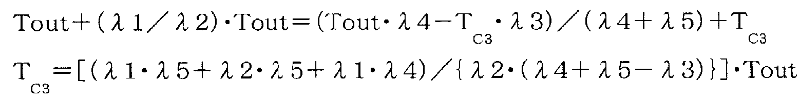
이 된다.Becomes
그리고 수학식 3에 수학식 6과 수학식 7을 대입함으로써,By substituting

이 된다.Becomes
여기서, 예를 들어 전진 4속단에 있어서 엔진 토크가 최고값이었다고 하여(입력 토크가 최고값이었다고 하여), 클러치(C-1)의 정상시의 토크 용량에 안전율을 곱한 값을 TC1, 클러치(C-2)의 정상시의 토크 용량에 안전율을 곱한 값을 TC2, 클러치(C-3)의 유압 서보(43)에 라인압(PL)이 공급된 경우의 토크 용량의 값을 TC3으로 하여, 상기 수학식 6, 7, 8에 상기 잇수비(λ1, λ2, λ3, λ4, λ5)와 함께 대입하면, 최악의 조건에서 고장이 발생하였을 때에 있어서의 각 클러치(C-1, C-2, C-3)의 토크 용량을 출력축 토크로 환산한 값을 산출할 수 있다.Here, for example, when the engine torque was the highest value at the 4th forward speed (the input torque was the highest value), the value obtained by multiplying the torque capacity at the normal time of the clutch C-1 by the safety factor is T C1 , the clutch ( C-2) is the value obtained by multiplying the torque capacity at the normal time by the safety factor T C2 , and the value of the torque capacity when the line pressure P L is supplied to the
이 산출 결과는 도 7에 나타내는 제5 페일 케이스(Fa5)이고, 즉 전진 4속단의 엔진(2)의 스로틀 완전 개방으로 주행 중에, 리니어 솔레노이드 밸브(SLC3)가 고장나 클러치(C-3)가 라인압(PL)으로 결합되어 버리고, 또한 액셀러레이터가 해방되어 엔진 토크(입력 토크)가 0으로 된 최악 조건이라도, 클러치(C-1)의 출력축 토크에 대한 환산값과, 클러치(C-2)의 출력축 토크에 대한 환산값이, 구동 차륜이 슬립하는 한계 토크(Ttire) 미만이 된다.The result of the calculation is the fifth fail case Fa5 shown in FIG. 7, that is, the linear solenoid valve SLC3 breaks down and the clutch C-3 breaks down while running at the full throttle of the
이로 인해, 출력축 토크에 대한 환산값이 가장 작아지는 클러치(C-1)[환언하면, 출력축(구동 차륜)으로부터 받는 토크가 가장 커지는 클러치(C-1)]는, 구동 차륜이 슬립하는 일 없이, 구동 차륜으로부터 받는 차량의 관성력에 기초하여 슬립되게 되어, 3개의 클러치(C-1, C-2, C-3)가 동시 결합하는 일 없이, 클러치(C-2, C-3)가 결합한 상태, 즉 전진 5속단의 상태로 되어, 스톨 상태로 되는 일 없이 주행 상태가 확보된다.For this reason, the clutch C-1 (in other words, the clutch C-1 in which the torque received from the output shaft (drive wheel) becomes the largest) that the converted value with respect to the output shaft torque is the smallest does not slip the driving wheel. And slip based on the inertia force of the vehicle received from the driving wheels, and the clutches C-2 and C-3 are engaged without the three clutches C-1, C-2 and C-3 simultaneously engaging. State, that is, a state of five forward speeds, and the running state is secured without becoming a stall state.
즉, 정상시의 전진 4속단에 있어서, 클러치(C-1, C-2)를 라인압(PL)으로 결합해 버리는 것이 아니라, 정상시 유압 설정 수단(72)에 의해, 입력 토크에 의해 슬립되지 않도록 안전율을 가미한, 가능한 한 낮은 유압인 결합압(PC1, PC2)으로 결합해 두도록 함으로써, 고장시에 클러치(C-3)가 결합되어 토크 분담이 변경된 것에 기초하여, 고장시에 있어서도 클러치(C-1)가 슬립되도록 설정되어 있게 되어, 이에 의해 고장이 발생해도 스톨 상태의 방지가 가능하게 되어 있다.That is, at the fourth forward speed in normal state, the clutches C-1 and C-2 are not coupled to the line pressure P L , but by the hydraulic pressure setting means 72 in the normal state by the input torque. By combining the coupling pressure P C1 and P C2 which are the lowest hydraulic pressures with the safety factor to prevent slipping, the clutch C-3 is engaged at the time of failure and the torque sharing is changed at the time of failure. Even when the clutch C-1 is set to slip, the stall state can be prevented even if a failure occurs.
이상의 설명에 있어서는, 전진 4속단에 있어서 고장에 의해 클러치(C-3)가 결합된 케이스인 제5 페일 케이스(Fa5)를 일례로 설명하였지만, 생각할 수 있는 모든 고장의 케이스인 제1 페일 케이스(Fa1) 내지 제4 페일 케이스(Fa4), 제6 페일 케이스(Fa6) 내지 제10 페일 케이스(Fa10)에 있어서도, 마찬가지로 토크 분담을 계산함으로써, 도 7에 나타내는 상태로 된다.In the above description, the fifth fail case Fa5, which is a case in which the clutch C-3 is coupled due to a failure at the fourth forward speed, has been described as an example. Also in Fa1) to 4th fail case Fa4 and 6th fail case Fa6 to 10th fail case Fa10, it is in the state shown in FIG. 7 by calculating torque sharing similarly.
즉, 전진 2속단에 있어서 상기 최악의 조건에 있어서의 리니어 솔레노이드 밸브(SLC2)의 고장에 의해 클러치(C-2)가 결합된 케이스인 제1 페일 케이스(Fa1)에서는, 고장에 의해 토크 분담이 변경되는 것에 기초하여, 브레이크(B-1)의 출력축 토크에 대한 환산값이 구동 차륜이 슬립하는 한계 토크(Ttire) 미만이 되어, 클러치(C-1, C-2)가 결합한 상태, 즉 전진 4속단의 상태로 되어, 스톨 상태로 되는 일 없이 주행 상태가 확보된다.That is, in the 1st fail case Fa1 which is a case in which the clutch C-2 was couple | bonded by the failure of the linear solenoid valve SLC2 in the 2nd forward speed in the said worst condition, torque sharing is broken by failure. Based on the change, the converted value with respect to the output shaft torque of the brake B-1 becomes less than the threshold torque Ttire at which the driving wheel slips, and the clutches C-1 and C-2 are engaged, that is, forward It becomes the state of four speeds, and a running state is ensured without becoming a stall state.
또한, 전진 2속단에 있어서 상기 최악의 조건에 있어서의 리니어 솔레노이드 밸브(SLC3)의 고장에 의해 클러치(C-3)가 결합된 케이스인 제2 페일 케이스(Fa2)에서는, 고장에 의해 토크 분담이 변경되는 것에 기초하여, 브레이크(B-1)의 출력축 토크에 대한 환산값이 구동 차륜이 슬립하는 한계 토크(Ttire) 미만이 되어, 클러치(C-1, C-3)가 결합한 상태, 즉 전진 3속단의 상태로 되어, 스톨 상태로 되는 일 없이 주행 상태가 확보된다.Further, in the second fail case Fa2, which is a case in which the clutch C-3 is coupled due to a failure of the linear solenoid valve SLC3 under the worst condition at the second forward speed, torque sharing is caused by the failure. Based on the change, the converted value with respect to the output shaft torque of the brake B-1 becomes less than the threshold torque Ttire at which the driving wheel slips, and the clutches C-1 and C-3 are engaged, that is, forward It becomes the state of three speeds, and a running state is ensured without becoming a stall state.
또한, 전진 3속단에 있어서 상기 최악의 조건에 있어서의 리니어 솔레노이드 밸브(SLC2)의 고장에 의해 클러치(C-2)가 결합된 케이스인 제3 페일 케이스(Fa3)에서는, 고장에 의해 토크 분담이 변경되는 것에 기초하여, 클러치(C-3)의 출력축 토크에 대한 환산값이 구동 차륜이 슬립하는 한계 토크(Ttire) 미만이 되어, 클러치(C-1, C-2)가 결합한 상태, 즉 전진 4속단의 상태로 되어, 스톨 상태로 되는 일 없이 주행 상태가 확보된다.Further, in the third fail case Fa3, which is a case in which the clutch C-2 is coupled due to a failure of the linear solenoid valve SLC2 under the worst condition at the third forward speed, torque sharing is caused by the failure. Based on the change, the converted value with respect to the output shaft torque of the clutch C-3 becomes less than the threshold torque Ttire at which the driving wheel slips, and the clutches C-1 and C-2 are engaged, that is, forward It becomes the state of four speeds, and a running state is ensured without becoming a stall state.
또한, 전진 3속단에 있어서 상기 최악의 조건에 있어서의 리니어 솔레노이드 밸브(SLB1)의 고장에 의해 브레이크(B-1)가 결합된 케이스인 제4 페일 케이스(Fa4)에서는, 고장에 의해 토크 분담이 변경되는 것에 기초하여, 브레이크(B-1)의 출력축 토크에 대한 환산값이 구동 차륜이 슬립하는 한계 토크(Ttire) 미만이 되어, 클러치(C-1, C-3)가 결합한 상태, 즉 전진 3속단의 상태로 되어, 스톨 상태로 되는 일 없이 주행 상태가 확보된다. 또한, 이 제4 페일 케이스(Fa4)에서는, 브레이크(B-1)의 유압 서보(44)에 라인압(PL)이 공급되게 되지만, 상술한 바와 같이 브레이크(B-1)의 브레이크 밴드의 권취 방향이 드럼 형상 부재(18)의 회전 방향과는 반대이며, 즉 구동 차륜의 회전에 의해 브레이크(B-1)가 느슨해지는 방향으로 회전되는 것과 아울러, 브레이크(B-1)의 출력축 토크에 대한 환산값이 특히 작아진다.Further, in the fourth failing case Fa4, which is a case in which the brake B-1 is coupled due to a failure of the linear solenoid valve SLB1 in the third worst case forward speed, torque sharing is caused by a failure. Based on the change, the converted value with respect to the output shaft torque of the brake B-1 becomes less than the threshold torque Ttire at which the driving wheel slips, and the clutches C-1 and C-3 are engaged, that is, forward It becomes the state of three speeds, and a running state is ensured without becoming a stall state. In addition, in the fourth fail case Fa4, the line pressure P L is supplied to the
또한, 전진 4속단에 있어서 상기 최악의 조건에 있어서의 리니어 솔레노이드 밸브(SLB1)의 고장에 의해 브레이크(B-1)가 결합된 케이스인 제6 페일 케이스(Fa6)에서는, 고장에 의해 토크 분담이 변경되는 것에 기초하여, 클러치(C-1)의 출력축 토크에 대한 환산값이 구동 차륜이 슬립하는 한계 토크(Ttire) 미만이 되어, 클러치(C-2), 브레이크(B-1)가 결합된 상태, 즉 전진 6속단의 상태로 되어, 스톨 상태로 되는 일 없이 주행 상태가 확보된다.Further, in the sixth fail case Fa6, which is a case in which the brake B-1 is coupled due to a failure of the linear solenoid valve SLB1 in the fourth worst case forward speed, torque sharing is caused by a failure. Based on the change, the converted value for the output shaft torque of the clutch C-1 becomes less than the threshold torque Ttire at which the driving wheel slips, so that the clutch C-2 and the brake B-1 are engaged. State, that is, a state of six forward speeds, and the running state is secured without becoming a stall state.
또한, 전진 5속단에 있어서 상기 최악의 조건에 있어서의 리니어 솔레노이드 밸브(SLC1)의 고장에 의해 클러치(C-1)가 결합된 케이스인 제7 페일 케이스(Fa7)에서는, 고장에 의해 토크 분담이 변경되는 것에 기초하여, 클러치(C-3)의 출력축 토크에 대한 환산값이 구동 차륜이 슬립하는 한계 토크(Ttire) 미만이 되어, 클러치(C-1, C-2)가 결합된 상태, 즉 전진 4속단의 상태로 되어, 스톨 상태로 되는 일 없이 주행 상태가 확보된다.Further, in the seventh fail case Fa7, which is a case in which the clutch C-1 is coupled due to a failure of the linear solenoid valve SLC1 in the fifth worst case forward speed, torque sharing is caused by a failure. Based on the change, the converted value with respect to the output shaft torque of the clutch C-3 becomes less than the limit torque Ttire at which the driving wheel slips, so that the clutches C-1 and C-2 are engaged, that is, It becomes the state of four forward speeds, and a running state is ensured without becoming a stall state.
또한, 전진 5속단에 있어서 상기 최악의 조건에 있어서의 리니어 솔레노이드 밸브(SLB1)의 고장에 의해 브레이크(B-1)가 결합된 케이스인 제8 페일 케이스(Fa8)에서는, 고장에 의해 토크 분담이 변경되는 것에 기초하여, 클러치(C-3)의 출력축 토크에 대한 환산값이 구동 차륜이 슬립하는 한계 토크(Ttire) 미만이 되어, 클러치(C-2), 브레이크(B-1)가 결합된 상태, 즉 전진 6속단의 상태로 되어, 스톨 상태로 되는 일 없이 주행 상태가 확보된다.Further, in the eighth failing case Fa8, which is a case in which the brake B-1 is coupled due to a failure of the linear solenoid valve SLB1 in the fifth worst case forward speed, torque sharing is caused by a failure. Based on the change, the converted value for the output shaft torque of the clutch C-3 becomes less than the threshold torque Ttire at which the driving wheel slips, so that the clutch C-2 and the brake B-1 are engaged. State, that is, the state of six forward speeds, ensures the running state without becoming a stall state.
또한, 전진 6속단에 있어서 상기 최악의 조건에 있어서의 리니어 솔레노이드 밸브(SLC1)의 고장에 의해 클러치(C-1)가 결합된 케이스인 제9 페일 케이스(Fa9)에서는, 고장에 의해 토크 분담이 변경되는 것에 기초하여, 브레이크(B-1)의 출력축 토크에 대한 환산값이 구동 차륜이 슬립하는 한계 토크(Ttire) 미만이 되어, 클러치(C-1, C-2)가 결합된 상태, 즉 전진 4속단의 상태로 되어, 스톨 상태로 되는 일 없이 주행 상태가 확보된다.Further, in the ninth fail case Fa9, which is a case in which the clutch C-1 is coupled due to a failure of the linear solenoid valve SLC1 in the sixth forward speed, the torque sharing is caused by a failure. Based on the change, the converted value for the output shaft torque of the brake B-1 becomes less than the threshold torque Ttire at which the driving wheel slips, so that the clutches C-1 and C-2 are engaged, that is, It becomes the state of four forward speeds, and a running state is ensured without becoming a stall state.
그리고 전진 6속단에 있어서 상기 최악의 조건에 있어서의 리니어 솔레노이드 밸브(SLC3)의 고장에 의해 클러치(C-3)가 결합된 케이스인 제10 페일 케이스(Fa10)에서는, 고장에 의해 토크 분담이 변경되는 것에 기초하여, 브레이크(B-1)의 출력축 토크에 대한 환산값이 구동 차륜이 슬립하는 한계 토크(Ttire) 미만이 되어, 클러치(C-2, C-3)가 결합된 상태, 즉 전진 5속단의 상태로 되어, 스톨 상태로 되는 일 없이 주행 상태가 확보된다.In the sixth forward case Fa10, which is a case in which the clutch C-3 is coupled due to failure of the linear solenoid valve SLC3 in the sixth forward speed, the torque sharing is changed by failure. On the basis of that, the converted value for the output shaft torque of the brake B-1 becomes less than the threshold torque Ttire at which the driving wheel slips, so that the clutches C-2 and C-3 are engaged, that is, forward It becomes the state of five speeds, and a running state is ensured without becoming a stall state.
또한, 상술한 바와 같이 브레이크(B-2)에 공급하는 결합압(PB2)은, 리니어 솔레노이드 밸브(SLC2)의 제어압(PSLC2)이고, C-2 릴레이 밸브(23)에 의해 절환하여 유압 서보(45)에 공급하므로, 리니어 솔레노이드 밸브(SLC2)가 고장난 경우는 유압 서보(42)에 제어압(PSLC2)이 공급되므로, 즉 고장에 의해 브레이크(B2)가 결합되어 버리는 일은 있을 수 없다. 또한, 전진 1속단에 있어서, 다른 클러치(C-2, C-3)나 브레이크(B-1)가 결합되어도, 변속단이 바뀔 뿐이며 3개의 마찰 결합 요소의 동시 결합은 발생하지 않는다. 이로 인해, 상술한 제1 내지 제10 페일 케이스(Fa1 내지 Fa10)가, 1개의 리니어 솔레노이드 밸브가 고장나는 싱글 페일로서 일어날 수 있는 모든 상태이다.As described above, the coupling pressure P B2 supplied to the brake B-2 is the control pressure P SLC2 of the linear solenoid valve SLC2 , and is switched by the C-2
또한, 이상 설명한 바와 같이 제1 내지 제10 페일 케이스(Fa1 내지 Fa10)가 발생하였다고 해도, 제9 페일 케이스(Fa9)에서 전진 6속단으로부터 전진 4속단이 되는 2단의 다운 시프트가 발생할 뿐이며, 다른 페일 케이스에서는 업 시프트, 혹은 1단의 다운 시프트가 발생할 뿐이므로, 특히 고장에 의해 차량의 주행 안정성에 큰 영향을 미칠 우려도 없다.In addition, even if the first to tenth fail cases Fa1 to Fa10 are generated as described above, only two downshifts from the sixth forward speed to the fourth forward speed occur in the ninth fail case Fa9. In the fail case, only an upshift or a downshift of one stage occurs, and therefore, there is no fear of particularly affecting the running stability of the vehicle due to a failure.
이상 설명한 바와 같이, 본 발명에 따르면, 정상시 유압 설정 수단(72)에 의해, 2개의 마찰 결합 요소(클러치, 브레이크)의 결합에 의해 변속단을 형성하고 있는 상태에서, 그들 2개의 마찰 결합 요소에 슬립이 발생하지 않도록, 또한 그들 2개의 마찰 결합 요소의 결합 중에 다른 마찰 결합 요소가 라인압(PL)에 기초하여 결합되었다고 해도, 그들 3개의 마찰 결합 요소 중 1개에 슬립이 발생하도록 2개의 마찰 결합 요소에 있어서의 결합압이 설정되므로, 2개의 마찰 결합 요소의 결합에 의한 변속단에서 주행하고 있는 상태에서는, 마찰 결합 요소에 슬립을 발생하는 일 없이, 구동원과 구동 차륜의 사이의 토크 전달을 행할 수 있는 것이면서, 다른 마찰 결합 요소가 결합되었을 때에는, 3개 중 1개의 마찰 결합 요소가 슬립됨으로써, 주행 상태를 확보할 수 있다. 이에 의해, 컷오프 밸브를 설치하는 것을 불필요하게 할 수 있어, 유압 제어 장치의 콤팩트화, 경량화, 비용 절감을 도모할 수 있다.As described above, according to the present invention, the two frictional engagement elements are formed by the hydraulic setting means 72 in normal state in the state where the speed change stage is formed by the engagement of the two frictional engagement elements (clutch, brake). So that no slip occurs, and even if another frictional engagement element is engaged based on the line pressure P L during the engagement of these two frictional engagement elements, the slippage occurs in one of those three frictional engagement elements. Since the engagement pressures in the two friction engagement elements are set, the torque between the drive source and the drive wheel without generating slip in the friction engagement element in the state of traveling at the shift stage by engagement of the two friction engagement elements. When the other frictional engagement element is engaged, the frictional engagement element of one of the three slips and the running state can be secured. . Thereby, it becomes unnecessary to provide a cutoff valve, and it can aim at the compactness, weight reduction, and cost reduction of a hydraulic control apparatus.
또한, 정상시 유압 설정 수단(72)이, 변속단을 형성하는 2개의 마찰 결합 요소의 토크 용량이, 산출된 2개의 마찰 결합 요소의 전달 토크에 안전율을 가미한 토크 용량이 되도록 결합압을 각각 설정하므로, 그들 2개의 마찰 결합 요소의 결합에 의한 변속단에서 주행하고 있는 상태에서 토크 변동이 있었다고 해도, 2개의 마찰 결합 요소에 확실하게 슬립이 발생하지 않도록 할 수 있다.Further, the normal hydraulic pressure setting means 72 sets the coupling pressures so that the torque capacities of the two frictional engagement elements forming the speed change stage are torque capacities of which the safety torque is added to the calculated transmission torques of the two frictional engagement elements. Therefore, even if there is a torque fluctuation in the state of traveling in the shift stage by the engagement of the two frictional engagement elements, it is possible to reliably prevent slippage between the two frictional engagement elements.
또한, 3개의 마찰 결합 요소 중 1개는 차량의 관성력에 의해 슬립되므로, 특히 엔진 등을 특별히 제어하는 일 없이, 그들 3개의 마찰 결합 요소 중 1개를 확실하게 슬립시킬 수 있다.In addition, since one of the three friction engagement elements is slipped by the inertia force of the vehicle, it is possible to reliably slip one of those three friction engagement elements without particularly controlling the engine or the like.
구체적으로는, 2개의 마찰 결합 요소의 결합 중에 다른 마찰 결합 요소가 결합되었을 때에, 3개의 마찰 결합 요소에 있어서의 토크 분담이 바뀌어, 3개의 마찰 결합 요소 중 1개가 구동 차륜이 슬립하는 한계 토크(Ttire) 미만이 됨으로써, 상기 1개의 마찰 결합 요소에 슬립이 발생하므로, 그들 3개의 마찰 결합 요소 중 1개를 확실하게 슬립시킬 수 있다.Specifically, when other frictional engagement elements are engaged during engagement of the two frictional engagement elements, the torque sharing in the three frictional engagement elements changes, so that one of the three frictional engagement elements slips at the limit torque at which the drive wheel slips ( By less than Ttire, slip occurs in the one frictional engagement element, so that one of the three frictional engagement elements can be reliably slipped.
또한, 자동 변속 기구는, 2개의 마찰 결합 요소의 결합 중에 다른 마찰 결합 요소가 결합되고, 그들 3개의 마찰 결합 요소 중 1개에 슬립이 발생하였을 때, 어느 하나의 변속단이 되므로, 주행 상태를 확보할 수 있다.In addition, the automatic transmission mechanism becomes one of the gear shift stages when another friction engagement element is engaged during engagement of the two friction engagement elements and slip occurs in one of the three friction engagement elements. It can be secured.
특히 본 자동 변속 기구(5)의 구성에 있어서는, 전진 2속단으로부터 전진 6속단까지에 있어서, 2개의 마찰 결합 요소(클러치나 브레이크)가 결합되어 있는 상태로부터, 다른 마찰 결합 요소가, 유압 서보에 라인압(PL)이 공급되는 상태로 되어도, 3개의 마찰 결합 요소의 동시 결합에 의해, 그들 3개의 마찰 결합 요소에 있어서의 토크 분담이 바뀜으로써, 출력축 토크로 환산하여 토크 분담이 가장 작아지는(구동 차륜으로부터 받는 토크가 가장 커지는) 마찰 결합 요소가, 구동 차륜에 대한 토크 용량으로서 차량의 관성력 미만으로 되어(구동 차륜으로부터 받는 토크가 정상시의 유압 설정에 의한 토크 용량을 상회하여), 슬립되도록 구성할 수 있고, 그것에 의해 주행 상태를 확보할 수 있다. 또한, 전진 1속단은, 클러치(C-1)의 결합과 원웨이 클러치(F-1)의 계지에 의해 달성되므로, 다른 마찰 결합 요소가 결합되어도, 어느 하나의 변속단으로 이행할 뿐이며, 주행 상태를 확보할 수 있다.In particular, in the configuration of the
또한, 브레이크(B-1)가 밴드 브레이크로 이루어지고, 상기 밴드 브레이크가, 전진 2속단으로부터 전진 6속단에 있어서의 드럼 형상 부재(18)의 회전 방향이, 브레이크 밴드(19)의 권취 방향과 역방향이 되도록 배치되어 있으므로, 브레이크(B-1)의 유압 서보(44)에 라인압(PL)이 공급되었다고 해도, 상기 브레이크(B-1)는 차량의 관성력에 의해 슬립되기 쉽도록 구성할 수 있고, 그것에 의해 특히 본 자동 변속 기구(5)의 구성에 있어서는, 어떠한 변속단의 상태로부터 다른 마찰 결합 요소가 결합되었다고 해도, 반드시 1개의 마찰 결합 요소에 슬립이 발생하도록 구성하는 것을 가능하게 할 수 있다.Further, the brake B-1 is a band brake, and the band brake has a rotational direction of the drum-shaped
또한, 본 유압 제어 장치(6)와 같이, 리니어 솔레노이드 밸브(SLC1, SLC2, SLC3, SLB1)가, 각각의 유압 서보(41, 42, 43, 44)에 대응하는 형태로 결합압(PC1, PC2, PC3, PB1)으로서 제어압(PSLC1, PSLC2, PSLC3, PSLB1)을 공급하는 구성으로 함으로써, 각 마찰 결합 요소의 토크 용량(유압 설정)을 개별로 설정할 수 있고, 각각의 마찰 결합 요소의 토크 용량을, 2개의 마찰 결합 요소에 의해 변속단을 형성하고 있을 때에는 슬립되지 않고, 또한 다른 마찰 결합 요소가 결합되었을 때에는 어느 하나가 슬립되도록 설정하는 것을 가능하게 할 수 있다.In addition, like the present
또한, 브레이크(B-2)가, 원웨이 클러치(F-1)와 병렬 배치되고, 전진 1속단의 코스트시에 캐리어(CR2)의 회전을 고정하는 브레이크로 이루어지고, 리니어 솔레노이드 밸브(SLC2)가 압력 조정한 제어압(PSLC2)을, C-2 릴레이 밸브(23)에 의해 클러치(C-2)의 유압 서보(42)와 브레이크(B-2)의 유압 서보(45)로 절환하여 공급하는 구성이므로, 특히 전진 1속단의 코스트시에 있어서의 브레이크(B-2)의 토크 용량은 작아도 충분하고, 또한 전진 1속단의 코스트 이외의 변속단에 있어서는 리니어 솔레노이드 밸브(SLC2)가 제어압(PSLC2)을 출력하였다고 해도 브레이크(B-2)가 결합되는 일이 없으므로 어떠한 변속단의 상태로부터 다른 마찰 결합 요소가 결합되었다고 해도, 반드시 1개의 마찰 결합 요소에 슬립이 발생하도록 구성하는 것을 가능하게 할 수 있다.In addition, the brake B-2 is arranged in parallel with the one-way clutch F-1, and constitutes a brake for fixing the rotation of the carrier CR2 at the cost of one forward speed, and the linear solenoid valve SLC2. The control pressure P SLC2 adjusted by the pressure is switched by the C-2
또한, 이상 설명한 본 실시 형태에 있어서는, 정상시에 결합하는 마찰 결합 요소의 유압을 설정할 때, 토크 분담 및 입력 토크에 기초하는 토크 용량에 안전율을 곱한 값의 토크 용량이 되도록 설정하고 있지만, 이 안전율은 구동원(엔진)의 출력 성능이나 구동 차륜의 그립 성능 등을 고려하여, 적절한 값으로 설정되어야 하는 것이며, 즉 변속단을 형성하는 2개의 마찰 결합 요소에 슬립이 발생하지 않도록, 또한 다른 마찰 결합 요소가 결합되었을 때에 어느 하나의 마찰 결합 요소가 슬립되도록 정상시의 유압 설정이 행해지는 것이면, 안전율은 어떠한 값이라도 좋고, 또한 정상시의 유압 설정의 산출 방법으로서도 어떠한 방법을 이용해도 좋다.In addition, in this embodiment demonstrated above, when setting the oil_pressure | hydraulic of the frictional engagement element to couple normally, it sets so that it may become torque capacity of the value which multiplied the safety factor by the torque capacity based on torque sharing and input torque, but this safety factor Should be set to an appropriate value in consideration of the output performance of the driving source (engine), the grip performance of the driving wheel, and so on, that is, to prevent slippage of the two frictional engagement elements forming the shift stage, When the hydraulic pressure setting at the time of normalization is performed so that any frictional engagement element slips when is combined, the safety factor may be any value, and any method may be used as a calculation method of the normal pressure setting.
또한, 이상 설명한 본 실시 형태의 자동 변속기(3)는, 전진 6속단을 달성할 수 있는 것을 일례로서 설명하였지만, 물론 이것에 한정되는 것은 아니며, 상술한 바와 같은 정상시의 유압 설정에 의해, 2개의 마찰 결합 요소에 의해 변속단을 형성하고 있을 때에는 그들 2개의 마찰 결합 요소가 슬립되지 않고, 다른 마찰 결합 요소가 결합되었을 때에는 3개 중 1개의 마찰 결합 요소가 슬립되어 동시 결합을 방지할 수 있는 자동 변속기이면, 어떠한 자동 변속기라도 본 발명을 적용할 수 있다.In addition, although the
본 발명에 관한 자동 변속기의 제어 장치는, 승용차, 트럭, 버스, 농기계 등에 탑재되는 자동 변속기에 이용하는 것이 가능하고, 특히 3개의 마찰 결합 요소가 동시 결합해도 주행 상태를 확보할 수 있고, 또한 콤팩트화, 경량화, 비용 절감이 요구되는 것에 이용하기 적합하다.The automatic transmission control device according to the present invention can be used for an automatic transmission mounted on a car, a truck, a bus, a farm machine, or the like. Particularly, even when three frictional engagement elements are simultaneously engaged, a running state can be secured and a compactness is achieved. It is suitable for use where weight reduction and cost reduction are required.
Claims (9)
구동원에 접속되는 입력축과, 구동 차륜에 접속되는 출력축을 갖고, 상기 복수의 마찰 결합 요소 중 2개의 결합 상태에 기초하여 상기 입력축과 상기 출력축의 사이의 전달 경로를 변경하여 복수의 변속단을 형성하는 자동 변속 기구와,
라인압을 자유롭게 압력 조정하여, 상기 결합압으로서 상기 각 유압 서보에 개별로 공급할 수 있는 압력 조정 공급부를 구비하고,
상기 변속단에 따라서 상기 마찰 결합 요소를 선택적으로 결합시키는 자동 변속기의 제어 장치에 있어서,
상기 입력축에 입력되는 입력 토크를 검출하는 입력 토크 검출 수단과,
상기 변속단을 형성하는 2개의 마찰 결합 요소에 있어서의 토크 분담을 판정하는 토크 분담 판정 수단과,
상기 입력 토크와 상기 토크 분담에 기초하여 상기 2개의 마찰 결합 요소에 있어서의 전달 토크를 산출하고, 상기 전달 토크를 전달할 수 있는 토크 용량이 되도록 상기 결합압을 각각 설정하는 정상시 유압 설정 수단을 구비하고,
상기 정상시 유압 설정 수단은,
상기 2개의 마찰 결합 요소의 결합에 의해 상기 변속단을 형성하고 있는 상태에서, 상기 2개의 마찰 결합 요소에 슬립이 발생하지 않도록, 또한 상기 2개의 마찰 결합 요소의 결합 중에 다른 마찰 결합 요소가 상기 라인압에 기초하여 결합되었다고 해도, 그들 3개의 마찰 결합 요소 중 1개에 슬립이 발생하도록 상기 결합압을 설정하는 것을 특징으로 하는, 자동 변속기의 제어 장치.A plurality of friction engagement elements coupled based on the engagement pressures supplied to each hydraulic servo,
An input shaft connected to a drive source, and an output shaft connected to a drive wheel, wherein a transmission path between the input shaft and the output shaft is changed based on two engagement states of the plurality of friction engagement elements to form a plurality of shift stages; With automatic transmission mechanism,
It is provided with the pressure regulation supply part which can pressure-adjust a line pressure freely and supply it to each said hydraulic servo individually as said coupling pressure,
A control apparatus of an automatic transmission for selectively engaging the friction engagement element in accordance with the speed change stage,
Input torque detecting means for detecting an input torque input to the input shaft;
Torque sharing determining means for determining torque sharing in two frictional engagement elements forming the speed change stage;
And normal hydraulic pressure setting means for calculating transmission torques in the two frictional engagement elements based on the input torque and the torque sharing, and setting the coupling pressures so as to be torque capacity capable of transmitting the transmission torques, respectively. and,
The normal hydraulic setting means,
In the state where the shift stage is formed by the engagement of the two frictional engagement elements, no slip occurs in the two frictional engagement elements, and another frictional engagement element is connected to the line during the engagement of the two frictional engagement elements. And the engagement pressure is set so that slip occurs in one of the three friction engagement elements even if the engagement is based on the pressure.
상기 입력축의 회전을 감속하는 감속 유성 기어와,
제1, 제2, 제3 및 제4 회전 요소를 갖고, 상기 제4 회전 요소가 상기 구동 차륜에 접속되는 유성 기어 세트와,
상기 감속 유성 기어의 감속 회전을 상기 제1 회전 요소에 전달 가능하게 하는 제1 클러치와,
상기 입력축의 회전을 상기 제2 회전 요소에 전달 가능하게 하는 제2 클러치와,
상기 감속 유성 기어의 감속 회전을 상기 제3 회전 요소에 전달 가능하게 하는 제3 클러치와,
상기 제3 회전 요소의 회전을 고정 가능하게 하는 제1 브레이크와,
상기 제2 회전 요소의 일방향 회전을 고정할 수 있는 원웨이 클러치를 구비하고,
전진 1속단에서, 상기 제1 클러치와 상기 원웨이 클러치가 결합되고,
전진 2속단에서, 상기 제1 클러치와 상기 제1 브레이크가 결합되고,
전진 3속단에서, 상기 제1 클러치와 상기 제3 클러치가 결합되고,
전진 4속단에서, 상기 제1 클러치와 상기 제2 클러치가 결합되고,
전진 5속단에서, 상기 제2 클러치와 상기 제3 클러치가 결합되고,
전진 6속단에서, 상기 제2 클러치와 상기 제1 브레이크가 결합되는 것을 특징으로 하는, 자동 변속기의 제어 장치.The method of claim 1, wherein the automatic transmission,
A deceleration planetary gear that decelerates rotation of the input shaft;
A planetary gear set having first, second, third and fourth rotating elements, wherein the fourth rotating element is connected to the drive wheel;
A first clutch which enables transmission of the deceleration rotation of the reduction planetary gear to the first rotating element;
A second clutch that enables transmission of the rotation of the input shaft to the second rotating element;
A third clutch enabling transmission of the deceleration rotation of the reduction planetary gear to the third rotating element;
A first brake for fixing the rotation of the third rotating element;
A one-way clutch capable of fixing one-way rotation of the second rotating element,
At the first forward speed, the first clutch and the one-way clutch are coupled,
At the second forward speed, the first clutch and the first brake are engaged,
At the third forward speed, the first clutch and the third clutch are engaged,
At the fourth forward speed, the first clutch and the second clutch are engaged,
In the fifth forward speed, the second clutch and the third clutch are engaged,
The sixth speed forward, characterized in that the second clutch and the first brake is coupled, the control device of the automatic transmission.
상기 밴드 브레이크는, 상기 전진 2속단으로부터 상기 전진 6속단에 있어서의 상기 드럼 형상 부재의 회전 방향이, 상기 브레이크 밴드의 권취 방향과 역방향이 되도록 배치되어 이루어지는 것을 특징으로 하는, 자동 변속기의 제어 장치.The said first brake is one end fixed to a case, the other end is drive-connected to the said hydraulic servo, and is wound up by the drum-shaped member connected to the said 3rd rotating element by the drive of the said hydraulic servo. Consisting of a band brake with a brake band,
The said band brake is arrange | positioned so that the rotation direction of the said drum-shaped member in the said 6th forward speed from the said 2nd forward speed may be reverse to the winding direction of the said brake band, The control apparatus of the automatic transmission characterized by the above-mentioned.
상기 제1 솔레노이드 밸브가 압력 조정한 결합압을, 상기 제1 클러치의 유압 서보에 공급하여 이루어지고,
상기 제2 솔레노이드 밸브가 압력 조정한 결합압을, 상기 제2 클러치의 유압 서보에 공급하여 이루어지고,
상기 제3 솔레노이드 밸브가 압력 조정한 결합압을, 상기 제3 클러치의 유압 서보에 공급하여 이루어지고,
상기 제4 솔레노이드 밸브가 압력 조정한 결합압을, 상기 제1 브레이크의 유압 서보에 공급하여 이루어지는 것을 특징으로 하는, 자동 변속기의 제어 장치.The said pressure regulation supply part has four solenoid valves of a 1st, 2nd, 3rd, and 4th solenoid valve,
It is made by supplying the combined pressure which the said 1st solenoid valve adjusted the pressure to the hydraulic servo of the said 1st clutch,
The second solenoid valve is provided by supplying the combined pressure adjusted by the pressure to the hydraulic servo of the second clutch,
The third solenoid valve is provided by supplying the combined pressure adjusted by the pressure to the hydraulic servo of the third clutch,
And a coupling pressure adjusted by the fourth solenoid valve to be supplied to the hydraulic servo of the first brake.
상기 제2 솔레노이드 밸브가 압력 조정한 결합압을, 상기 제2 클러치의 유압 서보와 상기 제2 브레이크의 유압 서보로 절환하여 공급하는 절환부를 구비하여 이루어지는 것을 특징으로 하는, 자동 변속기의 제어 장치.The second brake according to claim 8, wherein the second brake is disposed in parallel with the one-way clutch and fixes the rotation of the second rotating element at the cost of the first forward speed,
And a switching unit for switching and supplying the combined pressure adjusted by the second solenoid valve to the hydraulic servo of the second clutch and the hydraulic servo of the second brake.
Applications Claiming Priority (3)
| Application Number | Priority Date | Filing Date | Title |
|---|---|---|---|
| JP2007338146 | 2007-12-27 | ||
| JPJP-P-2007-338146 | 2007-12-27 | ||
| PCT/JP2008/067722 WO2009084294A1 (en) | 2007-12-27 | 2008-09-30 | Controller of automatic shift |
Publications (2)
| Publication Number | Publication Date |
|---|---|
| KR20100031137A KR20100031137A (en) | 2010-03-19 |
| KR101139184B1 true KR101139184B1 (en) | 2012-04-26 |
Family
ID=40799487
Family Applications (1)
| Application Number | Title | Priority Date | Filing Date |
|---|---|---|---|
| KR1020107002532A KR101139184B1 (en) | 2007-12-27 | 2008-09-30 | Controller of automatic shift |
Country Status (6)
| Country | Link |
|---|---|
| US (2) | US8255128B2 (en) |
| EP (1) | EP2166255B1 (en) |
| JP (1) | JP4998562B2 (en) |
| KR (1) | KR101139184B1 (en) |
| CN (1) | CN101779064B (en) |
| WO (1) | WO2009084294A1 (en) |
Families Citing this family (21)
| Publication number | Priority date | Publication date | Assignee | Title |
|---|---|---|---|---|
| DE102008054637A1 (en) * | 2008-12-15 | 2010-06-17 | Zf Friedrichshafen Ag | Hybrid powertrain of a motor vehicle |
| JP5262694B2 (en) | 2008-12-25 | 2013-08-14 | アイシン・エィ・ダブリュ株式会社 | Control device for automatic transmission |
| JP5152107B2 (en) * | 2009-06-15 | 2013-02-27 | アイシン・エィ・ダブリュ株式会社 | Control device for automatic transmission |
| WO2011027527A1 (en) | 2009-09-04 | 2011-03-10 | Aisin Aw Co., Ltd. | Control apparatus for automatic transmission and control method thereof |
| WO2011122533A1 (en) * | 2010-03-30 | 2011-10-06 | アイシン・エィ・ダブリュ株式会社 | Transmission device for vehicle |
| JP5494277B2 (en) * | 2010-06-22 | 2014-05-14 | アイシン・エィ・ダブリュ株式会社 | Hydraulic circuit device |
| US8795134B2 (en) | 2010-12-25 | 2014-08-05 | Toyota Jidosha Kabushiki Kaisha | Control apparatus for vehicular automatic transmission |
| CN103403403B (en) * | 2011-03-31 | 2015-08-12 | 爱信艾达株式会社 | The control gear of speed change gear and controlling method |
| JP5768875B2 (en) | 2011-03-31 | 2015-08-26 | アイシン・エィ・ダブリュ株式会社 | Transmission control device and transmission braking torque generation determination method |
| JP5386601B2 (en) * | 2012-03-12 | 2014-01-15 | トヨタ自動車株式会社 | Control device for automatic transmission |
| US8808141B2 (en) | 2012-05-07 | 2014-08-19 | Ford Global Technologies, Llc | Torque hole filling in a hybrid vehicle during automatic transmission shifting |
| US9488267B2 (en) | 2012-09-14 | 2016-11-08 | Ford Global Technologies, Llc | Line pressure control with input shaft torque measurement |
| US20150252892A1 (en) * | 2012-09-26 | 2015-09-10 | Jatco Ltd. | Automatic transmission equipped with friction element having locking mechanism attached thereto, and control method therefor |
| US8882636B2 (en) | 2012-11-27 | 2014-11-11 | Ford Global Technologies, Llc | Adjusting clutch slip based on sensed parameter of transmission shaft to control NVH level in vehicle powertrain |
| US8938340B2 (en) | 2013-03-13 | 2015-01-20 | Ford Global Technologies, Llc | Automatic transmission shift control based on clutch torque capacity detection using calculated transmission input torque |
| US9045125B2 (en) | 2013-03-15 | 2015-06-02 | Ford Global Technologies, Llc | Automatic transmission shift control based on torque phase detection using measured transmission input torque |
| JP6020430B2 (en) * | 2013-12-09 | 2016-11-02 | トヨタ自動車株式会社 | Vehicle control device |
| JP6197774B2 (en) * | 2014-09-30 | 2017-09-20 | トヨタ自動車株式会社 | Vehicle control device |
| JP6102894B2 (en) * | 2014-11-20 | 2017-03-29 | トヨタ自動車株式会社 | Control device for automatic transmission |
| JP6511943B2 (en) * | 2015-04-30 | 2019-05-15 | アイシン・エィ・ダブリュ株式会社 | Transmission |
| US10399557B2 (en) | 2017-11-10 | 2019-09-03 | Ford Global Technologies, Llc | Engine/motor torque control for torque hole filling in a hybrid vehicle during automatic transmission shifting |
Citations (3)
| Publication number | Priority date | Publication date | Assignee | Title |
|---|---|---|---|---|
| JPH0842681A (en) * | 1994-07-29 | 1996-02-16 | Honda Motor Co Ltd | Control device for hydraulically-operated transmission |
| JP2001248723A (en) | 2000-03-01 | 2001-09-14 | Honda Motor Co Ltd | Control device for vehicular automatic transmission |
| JP2003336731A (en) | 2002-05-17 | 2003-11-28 | Aisin Aw Co Ltd | Hydraulic control device |
Family Cites Families (12)
| Publication number | Priority date | Publication date | Assignee | Title |
|---|---|---|---|---|
| JP3861328B2 (en) * | 1996-06-19 | 2006-12-20 | アイシン・エィ・ダブリュ株式会社 | Control device for automatic transmission |
| JP2000335269A (en) * | 1999-05-27 | 2000-12-05 | Sumitomo Constr Mach Co Ltd | Transmitting device for construction machinery for road pavement |
| JP3797041B2 (en) * | 1999-10-08 | 2006-07-12 | トヨタ自動車株式会社 | Hydraulic control device for automatic transmission |
| JP4396002B2 (en) * | 2000-06-27 | 2010-01-13 | トヨタ自動車株式会社 | Vehicle traction control device |
| JP2004144108A (en) * | 2002-10-21 | 2004-05-20 | Nissan Diesel Motor Co Ltd | Shift control device for multistage transmission |
| DE112004000068D2 (en) * | 2003-05-02 | 2005-07-28 | Luk Lamellen & Kupplungsbau | Powertrain with a dual-clutch transmission and method for controlling the same |
| JP4085915B2 (en) * | 2003-07-03 | 2008-05-14 | トヨタ自動車株式会社 | Hydraulic control device for hydraulic machinery |
| JP2006528100A (en) * | 2003-07-21 | 2006-12-14 | ノーティテック プロプライエタリー リミテッド | Multi-speed transmission |
| KR20060073772A (en) * | 2004-12-24 | 2006-06-29 | 박동훈 | Powertrain of an automatic transmission |
| JP4667078B2 (en) * | 2005-03-07 | 2011-04-06 | トヨタ自動車株式会社 | Vehicle drive device |
| JP4333632B2 (en) * | 2005-05-09 | 2009-09-16 | トヨタ自動車株式会社 | Hydraulic control device for automatic transmission |
| JP2007024189A (en) * | 2005-07-15 | 2007-02-01 | Jatco Ltd | Change control device and method for automatic transmission |
-
2008
- 2008-09-30 JP JP2009547939A patent/JP4998562B2/en not_active Expired - Fee Related
- 2008-09-30 KR KR1020107002532A patent/KR101139184B1/en active IP Right Grant
- 2008-09-30 WO PCT/JP2008/067722 patent/WO2009084294A1/en active Application Filing
- 2008-09-30 EP EP08867640.8A patent/EP2166255B1/en active Active
- 2008-09-30 CN CN200880102188.3A patent/CN101779064B/en active Active
- 2008-12-17 US US12/314,814 patent/US8255128B2/en active Active
-
2012
- 2012-07-24 US US13/556,746 patent/US8543299B2/en active Active
Patent Citations (3)
| Publication number | Priority date | Publication date | Assignee | Title |
|---|---|---|---|---|
| JPH0842681A (en) * | 1994-07-29 | 1996-02-16 | Honda Motor Co Ltd | Control device for hydraulically-operated transmission |
| JP2001248723A (en) | 2000-03-01 | 2001-09-14 | Honda Motor Co Ltd | Control device for vehicular automatic transmission |
| JP2003336731A (en) | 2002-05-17 | 2003-11-28 | Aisin Aw Co Ltd | Hydraulic control device |
Also Published As
| Publication number | Publication date |
|---|---|
| US8543299B2 (en) | 2013-09-24 |
| KR20100031137A (en) | 2010-03-19 |
| EP2166255B1 (en) | 2013-12-04 |
| US20090171545A1 (en) | 2009-07-02 |
| WO2009084294A1 (en) | 2009-07-09 |
| CN101779064B (en) | 2013-01-02 |
| JP4998562B2 (en) | 2012-08-15 |
| US8255128B2 (en) | 2012-08-28 |
| CN101779064A (en) | 2010-07-14 |
| JPWO2009084294A1 (en) | 2011-05-12 |
| US20120290180A1 (en) | 2012-11-15 |
| EP2166255A4 (en) | 2012-01-18 |
| EP2166255A1 (en) | 2010-03-24 |
Similar Documents
| Publication | Publication Date | Title |
|---|---|---|
| KR101139184B1 (en) | Controller of automatic shift | |
| KR101096834B1 (en) | Hydraulic control device for automatic transmission | |
| EP2256376B1 (en) | Hydraulic control device for automatic transmission | |
| US7951034B2 (en) | Hydraulic control apparatus for automatic transmission | |
| CN102016352B (en) | Automatic transmission | |
| JP2009133435A (en) | Hydraulic control device of automatic transmission | |
| JP5115473B2 (en) | Control device for automatic transmission | |
| JP2011214678A (en) | Hydraulic control device for lock-up clutch | |
| JP2009133436A (en) | Hydraulic control device of automatic transmission | |
| JP5131247B2 (en) | Control device for automatic transmission | |
| JP5126056B2 (en) | Control device for automatic transmission | |
| JPH1130330A (en) | Shift controller for automatic transmission |
Legal Events
| Date | Code | Title | Description |
|---|---|---|---|
| A201 | Request for examination | ||
| E902 | Notification of reason for refusal | ||
| E701 | Decision to grant or registration of patent right | ||
| GRNT | Written decision to grant | ||
| FPAY | Annual fee payment |
Payment date: 20160318 Year of fee payment: 5 |
|
| FPAY | Annual fee payment |
Payment date: 20170322 Year of fee payment: 6 |
|
| FPAY | Annual fee payment |
Payment date: 20180403 Year of fee payment: 7 |
|
| FPAY | Annual fee payment |
Payment date: 20190328 Year of fee payment: 8 |