US8704888B2 - Imaging device and image analysis method - Google Patents
Imaging device and image analysis method Download PDFInfo
- Publication number
- US8704888B2 US8704888B2 US13/565,031 US201213565031A US8704888B2 US 8704888 B2 US8704888 B2 US 8704888B2 US 201213565031 A US201213565031 A US 201213565031A US 8704888 B2 US8704888 B2 US 8704888B2
- Authority
- US
- United States
- Prior art keywords
- ball
- image
- frame
- calculating
- center position
- Prior art date
- Legal status (The legal status is an assumption and is not a legal conclusion. Google has not performed a legal analysis and makes no representation as to the accuracy of the status listed.)
- Active, expires
Links
Images


Classifications
-
- G—PHYSICS
- G06—COMPUTING; CALCULATING OR COUNTING
- G06T—IMAGE DATA PROCESSING OR GENERATION, IN GENERAL
- G06T7/00—Image analysis
- G06T7/20—Analysis of motion
-
- G—PHYSICS
- G06—COMPUTING; CALCULATING OR COUNTING
- G06T—IMAGE DATA PROCESSING OR GENERATION, IN GENERAL
- G06T7/00—Image analysis
- G06T7/60—Analysis of geometric attributes
-
- G—PHYSICS
- G06—COMPUTING; CALCULATING OR COUNTING
- G06T—IMAGE DATA PROCESSING OR GENERATION, IN GENERAL
- G06T7/00—Image analysis
- G06T7/20—Analysis of motion
- G06T7/246—Analysis of motion using feature-based methods, e.g. the tracking of corners or segments
-
- H—ELECTRICITY
- H04—ELECTRIC COMMUNICATION TECHNIQUE
- H04N—PICTORIAL COMMUNICATION, e.g. TELEVISION
- H04N25/00—Circuitry of solid-state image sensors [SSIS]; Control thereof
- H04N25/50—Control of the SSIS exposure
- H04N25/53—Control of the integration time
- H04N25/531—Control of the integration time by controlling rolling shutters in CMOS SSIS
-
- G—PHYSICS
- G06—COMPUTING; CALCULATING OR COUNTING
- G06T—IMAGE DATA PROCESSING OR GENERATION, IN GENERAL
- G06T2207/00—Indexing scheme for image analysis or image enhancement
- G06T2207/30—Subject of image; Context of image processing
- G06T2207/30204—Marker
-
- G—PHYSICS
- G06—COMPUTING; CALCULATING OR COUNTING
- G06T—IMAGE DATA PROCESSING OR GENERATION, IN GENERAL
- G06T2207/00—Indexing scheme for image analysis or image enhancement
- G06T2207/30—Subject of image; Context of image processing
- G06T2207/30221—Sports video; Sports image
-
- G—PHYSICS
- G06—COMPUTING; CALCULATING OR COUNTING
- G06T—IMAGE DATA PROCESSING OR GENERATION, IN GENERAL
- G06T2207/00—Indexing scheme for image analysis or image enhancement
- G06T2207/30—Subject of image; Context of image processing
- G06T2207/30221—Sports video; Sports image
- G06T2207/30224—Ball; Puck
-
- G—PHYSICS
- G06—COMPUTING; CALCULATING OR COUNTING
- G06T—IMAGE DATA PROCESSING OR GENERATION, IN GENERAL
- G06T2207/00—Indexing scheme for image analysis or image enhancement
- G06T2207/30—Subject of image; Context of image processing
- G06T2207/30241—Trajectory
-
- G06T7/0097—
Definitions
- the present invention relates to an imaging device (image pickup device) and an image analysis method that can analyze a movement of a ball from an image in a frame captured by an image pickup means using a rolling shutter system.
- a speed-gun is well known as a device for measuring a speed of a ball used for a sport such as baseball, tennis, and the like.
- a speed-gun measures the Doppler effect of reflected waves from a ball, for example, and estimates a ball speed. Therefore, such a speed-gun has to be placed along a movement direction of the ball and thus there is high risk of collision with the ball. In addition, there is a problem that it is difficult to confirm at which position of the moving ball the speed was measured.
- JP2001-264016A Patent Document 1
- a method for measuring a speed of a moving ball by capturing an image of a ball from a direction orthogonal to the moving direction and analyze the image is disclosed (JP2001-264016A, Patent Document 1, for example).
- the technique disclosed in the document is as follows. When an impact on a ball is detected by a trigger sensor, a mechanical shutter repeatedly opens and shuts while a flash unit fires repeatedly in synchronism with the movement of the shutter so as to capture multiple ball images in an image frame using a CCD camera.
- Patent Document 1 requires a large scale system including a flash unit, a trigger sensor and the like as well as a CCD camera. Therefore, it is also conceivable to utilize a high-speed camera that can capture continuous frames as still images rapidly instead of a multiple exposure system so as to save a flash unit, and the like.
- an image sensor for a high-speed camera is a CMOS-type image sensor that can capture images in high-speed instead of a CCD-type image sensor.
- the CMOS-type image sensor captures images using a rolling shutter system that exposes and accumulates electrical charges horizontal line by line. Consequently, the ball image in a frame becomes deformed when a high-speed moving ball is captured. Thus it is difficult to analyze the ball movement accurately using a deformed image of the moving ball in the frame.
- an imaging device that includes an image pickup portion of a rolling shutter system, an image pickup controlling portion for controlling the image pickup portion so as to pickup at least two frame images by continuous image capturing, each of the images containing a ball image elliptically deformed, a separability calculating portion for calculating a separability of pixels between an inside region and an outside region by filtering the frame images captured by the image pickup controlling portion using an ellipse separability filter having the inside region of an ellipse shape whose major axis is inclined with respect to a horizontal line and the outside region that is adjacent to the inside region, an estimating portion for estimating a set of a center position, major axis, minor axis and inclination angle of the elliptical inside region, the set resulting in a maximum separability by changing the center position, major axis, minor axis and inclination angle of the inside region, as a set of a center position, major axi
- an imaging device that includes an image pickup portion of a rolling shutter system, an image pickup controlling portion for controlling the image pickup portion so as to pickup a frame image by an image capturing, the frame image containing a ball image elliptically deformed, a separability calculating portion for calculating a separability of pixels between an inside region and an outside region by filtering the frame image captured by the image pickup controlling portion using an ellipse separability filter having the inside region of an ellipse shape whose major axis is inclined with respect to a horizontal line and the outside region located adjacently and concentrically outside the inside region, an estimating portion for estimating a set of a center position, major axis, minor axis and inclination angle of the elliptical inside region, the set resulting in a maximum separability by changing the center position, major axis, minor axis and inclination angle of the inside region, as a set of a center position, major axis, minor
- a method for analyzing an imaging that includes a step of calculating a separability of pixels, for at least two frame images each image being continuously captured by an image pickup portion with a rolling shutter system and thus containing a moving ball image elliptically deformed, between an inside region and an outside region by filtering the frame images using an ellipse separability filter having the inside region of an ellipse shape whose major axis is inclined with respect to a horizontal line and the outside region that is adjacent to the inside region, a step of estimating a set of a center position, major axis, minor axis and inclination angle of the inside region, the set resulting in a maximum separability obtained in the separability calculating step by changing the center position, major axis, minor axis and inclination angle of the inside region, as a set of a center position, major axis, minor axis and inclination angle of the ball image, and a step of calculating
- a method for analyzing an imaging that includes a step of calculating a separability of pixels, for a frame image being captured by an image pickup portion with a rolling shutter system and thus containing a moving ball image elliptically deformed, between an inside region and an outside region by filtering the frame image using an ellipse separability filter having the inside region of an ellipse shape whose major axis is inclined with respect to a horizontal line and the outside region located adjacently and concentrically outside the inside region, a step of estimating a set of a center position, major axis, minor axis and inclination angle, the set resulting in a maximum separability obtained in the separability calculating step by changing the center position, major axis, minor axis and inclination angle, as a set of a center position, major axis, minor axis and inclination angle of the ball image, a step of calculating tangent points (first intersection points) of
- FIG. 1 is a plan view indicating a usage state of an imaging device according to a first exemplary embodiment of the present invention
- FIG. 2 is a ball used for an embodiment
- FIG. 3 is a structural block diagram of an imaging device
- FIG. 4 is a flowchart of a main routine process performed by a computer of an imaging device
- FIG. 5 is an example of a captured image of a still ball
- FIG. 6 is an example of a captured image of a moving ball
- FIG. 7 is a flowchart of a sub-routine process performed by a computer of an imaging device
- FIG. 8 is a flowchart of a sub-sub-routine process performed by a computer of an imaging device
- FIG. 9 is an image in a frame before impact
- FIG. 10 shows images of a ball in frames
- FIG. 11 is a graph showing a relation between a frame index and a difference
- FIG. 12 is a flowchart of a sub-sub-routine process performed by a computer of an imaging device
- FIG. 13 is a graph showing a relation between a frame index and a difference
- FIG. 14 is a flowchart of a sub-routine process performed by a computer of an imaging device
- FIG. 15 is a flowchart of a sub-sub-routine process performed by a computer of an imaging device
- FIG. 16 is a flowchart of a sub-sub-routine process performed by a computer of an imaging device
- FIG. 17 is a drawing for explaining a circular separability filter
- FIG. 18 is a flowchart of a sub-routine process performed by a computer of an imaging device
- FIG. 19 is a flowchart of a sub-sub-routine process performed by a computer of an imaging device
- FIG. 20 is a drawing for explaining a smoothing processing of a background of a ball image
- FIG. 21 is a drawing for explaining an ellipse separability filter
- FIG. 22 is a flowchart of a sub-routine process performed by a computer of an imaging device
- FIG. 23 is a flowchart of a sub-sub-routine process performed by a computer of an imaging device
- FIG. 24A is a ball image before a deformation correction
- FIG. 24B is a ball image after a deformation correction
- FIG. 25 is a flowchart of a sub-sub-routine process performed by a computer of an imaging device
- FIG. 26 is a drawing for explaining a calculation of a horizontal take-off angle of a ball
- FIG. 27 is a structural block diagram of an imaging device according to a second exemplary embodiment of the invention.
- FIG. 28 is a flowchart of a main-routine process performed by a computer of an imaging device.
- FIG. 29 is a drawing for explaining a principle for analyzing a movement of a ball.
- FIG. 1 is a plan view illustrating a usage state of an imaging device 100 according to an exemplary embodiment of the present invention.
- the imaging device 100 is arranged such that an image pickup direction D is almost horizontal and a hitter 201 hits a round ball 202 to a direction F that is orthogonal to the image pickup direction D within an image pickup area E of the imaging device 100 . It is arranged such that the ball 202 at the time of hitting is within the image pickup area E of the imaging device 100 .
- the imaging device 100 captures continuous images such that the ball 202 is contained in each frame from the rest state before hitting to the moving state in high speed after hitting.
- the imaging device 100 analyzes a speed, hitting direction, rotating state, etc. of the ball 202 based on the frame images (also referred to as “frame” or “frames” simply hereinafter) in which the images of the ball 202 are captured continuously.
- a color of the ball 202 is white and the background is dark so as to pickup the images of the ball 202 clearly. It is also preferable to attach a mark and/or a pattern on a surface of the ball 202 so that the rotating state of the ball 202 can be analyzed easily. As shown in FIG. 2 , for example, circumferential lines 203 and 204 intersecting at right angles are attached on a surface of the ball 202 .
- FIG. 3 is a structural block diagram of the imaging device 100 .
- the imaging device 100 is a ball movement analyzing device and preferably a digital camera.
- the imaging device 100 includes a lens unit 1 , lens driving portion 2 , electronic image pickup portion 3 , unit circuit 4 , image pickup controlling portion 5 , image generating portion 6 , image processing portion 7 , operation input portion 8 , display portion 9 , reader/writer 10 , buffer memory 12 , program memory 13 , central control portion 14 , and the like.
- a memory portion 11 as an external memory medium is mounted on the imaging device 100 .
- the lens driving portion 2 , image pickup controlling portion 5 , image generating portion 6 , image processing portion 7 , display portion 9 , reader/writer 10 , buffer memory 12 , program memory 13 and central control portion 14 are connected each other via a bus line 15 .
- a computer of the imaging device 100 is composed of the image processing portion 7 , buffer memory 12 , central control portion 14 and bus line 15 .
- the operation input portion 8 Upon an operation by a user, the operation input portion 8 outputs corresponding operational signals to the central control portion 14 .
- the operation input portion 8 includes, for example, operation buttons such as a shutter button 8 a , mode selection button 8 b and direction operation button 8 c and a touch panel 8 d provided on a display surface of the display portion 9 .
- the shutter button 8 a is used for instructing an image pickup by the electronic image pickup portion 3 .
- the mode selection button 8 b is used for selecting an imaging mode among a normal imaging mode, continuous imaging mode, ball movement analyzing mode, and the like.
- the direction operation button 8 c is used for moving a cursor on the display surface of the display portion 9 .
- the touch panel 8 d is used for inputting various instructions by touching various positions.
- the lens unit 1 is composed of a plurality of lenses and has a focusing function and a zoom function.
- the lens unit 1 forms an image of a subject to be imaged (mainly the ball 202 ) in front of the lens unit 1 and its background on the electronic image pickup portion 3 .
- the lens driving portion 2 moves each lens of the lens unit 1 along the optical axis thereof.
- the lens driving portion 2 is provided with a driving source, such as a focusing motor, to move the lenses along the optical axis and a driver to activate the driving source (both not shown).
- the electronic image pickup portion 3 is arranged behind the lens unit 1 on the optical axis of the lens unit 1 .
- the portion 3 is constituted from an image sensor such as a CMOS (Complementary Metal-Oxide Semiconductor), for example.
- the portion 3 converts an optical image formed by the lens unit 1 into two-dimension image signals.
- the portion 3 can capture continuous frame images rapidly. That is, the portion 3 captures frame images continuously containing the subject such as the ball 202 on movement and outputs the plurality of image frames to the unit circuit 4 in turn.
- a rate of continuous image frame capturing by the portion 3 is designated as F rate (fps).
- the portion 3 performs image pickup by a rolling shutter system. In other words, the image sensor of the portion 3 exposes and accumulates electric charges for each horizontal line.
- the number of vertical lines of the portion 3 is designated as Sx and the number of horizontal lines is designated as Sy.
- Analogue image signals corresponding to the optical image of the subject output from the portion 3 is input to the unit circuit 4 .
- the unit circuit 4 is composed of a CDS for storing the analog image signals, a gain adjustable amplifier (AGC) for amplifying the image signals, an A/D converter (ADC) for converting the image signals amplified by the gain adjustable amplifier into digital image data, and so on (all not shown).
- ADC gain adjustable amplifier
- ADC A/D converter
- the image pickup controlling portion 5 controls the electronic image pickup portion 3 and the unit circuit 4 so as to activate the portion and the circuit at the timing in accordance with the frame rate set by the central control portion 14 .
- the portion 5 includes a TG (Timing Generator), a driver to activate the electronic image pickup portion 3 (both not shown), and so on and controls the operation timing of the driver and the unit circuit 4 through the TG. That is, after setting the shutter speed by the central control portion 14 in accordance with a program 13 a read from the program memory 13 , the TG of the portion 5 outputs an electric charge accumulation time corresponding to the shutter speed as a shutter pulse to the driver and activates the electronic image pickup portion 3 of the rolling shutter system in accordance with activating pulse signals from the driver so as to control the electric charge accumulation time (exposure time). An image for one frame is captured by the electronic image pickup portion 3 in this way. For capturing continuous frames, after setting a frame rate by the central control portion 14 , the portion 5 activates the electronic image pickup portion 3 of the rolling shutter system repeatedly in accordance with the frame rate so as to have the portion 3 capture images continuously.
- TG Temporal Generator
- the image generating portion 6 performs various processing to the image output from the unit circuit 4 such as a gamma correction processing, white balance processing, and the like.
- the portion 6 outputs the processed image to the reader/writer 10 under the control of the central control portion 14 .
- the reader/writer 10 stores the processed images in the memory portion 11 .
- the memory portion 11 is a nonvolatile semiconductor memory or a hard disc and stores the images.
- an image which is processed by the image generating portion 6 is recorded in the memory portion 11 by the reader/writer 10 .
- an image processed by the portion 6 is temporarily stored in the buffer memory 12 and the display portion 9 converts the temporarily-stored image in the buffer memory 12 into video signals and display the image on the display surface as a live view image.
- the reader/writer 10 reads the image stored in the memory portion 11 .
- the image read out by the reader/writer 10 is stored temporarily in the buffer memory 12 .
- the image temporarily stored in the buffer memory 12 can be converted into video signals by the display portion 9 and/or processed by the image processing portion 7 .
- the buffer memory 12 is a buffer for storing images temporarily and can be used as a working memory for the central control portion 14 .
- the program memory 13 stores the program 13 a and various data for functioning the imaging device 100 .
- the program 13 a is a program readable by the central control portion 14 and the image processing portion 7 .
- the central control portion 14 has a CPU (not shown) for controlling each portion of the imaging device 100 .
- the program 13 a makes the central control portion 14 function as an initial position setting means 14 a , image pickup controlling means 14 b , input controlling means 14 c , and the like and the central control portion 14 controls each portion of the imaging device 100 in accordance with the program 13 a .
- the functions of the central control portion 14 will be explained later.
- the image processing portion 7 has a processor (not shown) for image processing such as an operation about coordinates of each pixel of an image, an operation about a pixel value for each pixel, and the like.
- the portion 7 processes images according to the program 13 a . That is, the program 13 a makes the portion 7 function as a hitting-time (impact) frame detecting means 7 a , first smoothing means 7 b , circular separability calculating means 7 c , first estimating means 7 d , average color calculating means 7 e , second smoothing means 7 f , ellipse separability calculating means 7 g , second estimating means 7 h , deviation amount calculating means 7 i , shifting amount calculating means 7 j , deformation correction means 7 k , coordinates transforming means 7 m , rotation angle estimating means 7 n , speed calculating means 7 p , vertical take-off (ejection) angle calculating means 7 s and spin speed calculating means 7 t , horizontal
- the imaging device 100 Before performing following processing by the central control portion 14 and the image processing portion 7 , the imaging device 100 have to be set as indicated in FIG. 1 .
- the central control portion 14 functions as an initial position determining means 14 a by the program 13 a and sets an initial position (X ini , Y ini ) of the ball in a two dimensional rectangular coordinates system in which positions of the image pixels are expressed (step S 1 ). Specifically, by operating the direction operating button 8 c , a user moves the cursor onto the ball image in a live view image (the live view image is picked up by the electronic image pickup portion 3 and displayed on the display portion 9 ). Then the portion 14 determines the position of the cursor as the initial position (X ini , Y ini ).
- a user can touch the ball position on the touch panel 8 d of the live view image so that the portion 14 determines the touched position as the initial position (X ini , Y ini ). Or after setting an initial position (X ini , Y ini ) by the portion 14 , a user can move the imaging device 100 such that a rectangle, the center of which will become an initial position (X ini , Y ini ) of the ball, displayed in the live view image comes to the position of the ball.
- An appropriate gain by which a user can confirm the live view image easily is set in the unit circuit 4 at the initial position (X ini , Y ini ) determining step.
- a horizontal line of the pixel matrix (a horizontal pixel line) of the electronic image pickup portion 3 is the x-direction of the two dimensional rectangular coordinates system and the vertical line (a vertical pixel line) is the y-direction of the two dimensional rectangular coordinates system.
- the central control portion 14 plays a role as the image pickup controlling means 14 b by the program 13 a and picks up images continuously (step S 2 ). Specifically, upon pressing the shutter button 8 a by a user, the portion 14 sets the activation timing and the frame rate (F rate ) of the unit circuit 4 and the electronic image pickup portion 3 .
- the image pickup controlling portion 5 activates the portion 3 repeatedly in accordance with the activation timing and the frame rate by the rolling shutter system so as to pickup continuous image frames rapidly. It is preferable that a shutter speed of the portion 3 is as fast as possible and the frame rate f rate is as high as possible.
- the hitter 201 hits the ball 202 during the continuous image capturing.
- a plurality of frame images containing the ball image from the point of time the ball 202 is still to the time the ball is moving are continuously captured by the portion 3 .
- the images captured by the portion 3 are output to the reader/writer 10 in turn through the unit circuit 4 and the image generating portion 6 and the reader/writer 10 stores the images in the memory portion 11 in turn.
- the image processing portion 7 stores image pickup conditions (horizontal angle of view A H and vertical angle of view A V of the lens unit, frame rate (F rate ), etc.) during the continuous shooting in the memory portion 11 as well.
- a gain of an analog stage (gain adjustment amplifier) before an A/D inverter of the unit circuit 4 is preferably set as high as possible when signals of the continuous images captured by the electronic image pickup portion 3 are processed by the unit circuit 4 .
- FIG. 5 is an image of the ball in a frame before hitting (impact) of the ball 202
- FIG. 6 is an image of the ball in a frame after hitting (impact) of the ball 202 .
- FIG. 5 when the ball 202 is still, the ball image is circular (not deformed) and when the ball 202 is moving, the ball image is deformed into an ellipse.
- FIG. 6 is an image under assumptions that the ball 202 moves from left to right in front of the imaging device 100 and the image sensor of the portion 3 exposes and accumulates charges horizontally from up to down.
- a user can operate the direction operating button 8 c so as to set the cursor on the ball position or touch the ball position on the touch panel 8 d so that the central control portion 14 can determine the initial position (X ini , Y ini ) based on the cursor position or touch position when the first frame or a later frame is displayed on the display portion 9 after continuous image capturing.
- the central control portion 14 functions as the input controlling means 14 c by the program 13 a and stores the data input through the operation input portion 8 to the buffer memory 12 , and the like.
- a user operates the operation input portion 8 so that the user inputs various image pickup conditions such as a size of the ball 202 and an imaging distance (a distance between a subject plane that is orthogonal to the image pickup direction D and passes through the ball 202 before impact and the imaging device 100 (lens unit 1 and the portion 3 , etc.)), for example, and the central control portion 14 stores the input conditions in the buffer memory 12 .
- the image processing portion 7 functions as the impact frame detecting means 7 a by the program 13 a and detects the frame at the point of time the ball 202 is hit (impact frame) among the continuous frames stored in the memory portion 11 (step S 3 ).
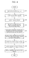
- the process in the step S 3 to detect the impact frame which the ball 202 is hit will be explained with reference to the flowchart in FIG. 7 .
- the image processing portion 7 picks out a choice of the impact frame (step S 11 ), specifies the impact frame among the frames around the choice frame (step S 12 ) and outputs the impact frame to the display portion 9 so as to display the frame on the display portion 9 (step S 13 ).
- FIG. 8 is a flowchart for explaining the step to pick up a choice of the impact frame (step S 11 ) in detail.
- the image processing portion 7 sets a rectangular region W (see FIG. 9 ) the center of which is the initial position (X ini , Y ini ) set by the central control portion 14 (step S 21 ).
- FIG. 9 explains the region W and the whole frame containing the ball image before impact is shown with the region W in FIG. 9 .
- the size of the region W (a size in the x direction is designated as wx and in the y direction is designated as wy, respectively) is within the size of the ball image.
- a shape of the region W is not necessarily a rectangle.
- the image processing portion 7 reads out a t-th frame from the top and a frame that is N frames prior to the t-th frame among the continuous frames stored in the memory portion 11 .
- the number N is an integer of 2 or more and preferably large enough based on a time that the ball passes through the region W and the frame rate.
- the portion 7 calculates a difference between the region W of the t-th frame and the region W of the (t-N)th frame (step S 22 , S 23 and S 24 ). Specifically, as shown in the following formula 1, the portion 7 calculates a sum of absolute differences of pixel values of the same pixels between the t-th frame and the previous frame in the region W.
- t is a frame index
- ft(x, y) is a pixel value of each pixel in the t-th frame
- f t ⁇ N (x, y) is a pixel value of each pixel in the (t ⁇ N)th frame
- difW 1 ( t ) is a difference in the region W between the t-th frame and the previous frame.
- the image processing portion 7 calculates the difference difW 1 ( t ) of the region W between two frames every Nth frame (step S 25 : NO).
- the portion 7 determines a frame having the largest difference difW 1 ( t ) as a choice of an impact frame (step S 26 ).
- a frame index of the choice frame is designated as N 1 hereinafter. Since calculations of the differences difW 1 ( t ) are executed every Nth frame, the burden of the calculation process can be reduced.
- FIG. 10 shows the situations of the ball in the Nth frame, (N 1 ⁇ N)th frame and (N 1 ⁇ 2N)th frame.
- FIG. 11 is a graph showing calculated difference for each frame every Nth frame. The horizontal axis of FIG. 11 is a frame index and the vertical axis is a difference difW 1 ( t ).
- the ball is still in the (N 1 ⁇ N)th frame that is before the frame N 1 in which the ball 202 is impacted.
- the ball image is out of the region W and an image of a hitting body (the head of a golf club, for example) is passing through the region W.
- a hitting body the head of a golf club, for example
- the N 1 th frame has the largest difference difW 1 ( t ) between the regions W of two frames every Nth frame.
- the frame having the largest difference difW 1 ( t ) is determined as a choice of the impact frame.
- the portion 7 executes steps shown in FIG. 12 to determine the frame.
- FIG. 12 is a flowchart explaining a process (step S 12 ) to determine the impact frame.
- the image processing portion 7 reads out a (N 1 ⁇ 2N)th frame that is 2N frames prior to the N 1 th frame determined at the step S 26 in FIG. 8 (step S 31 ).
- a region W of the frame is set as a template (step S 32 ).
- the image processing portion 7 reads out a next frame from the memory portion 11 (step S 33 ) and calculates a difference between a region W of the (N 1 ⁇ 2N)th frame as the template and a region W of the next frame (step S 34 ). Specifically, as shown in the next formula, the portion 7 calculates a sum of the absolute differences of pixel values of the same pixels between the (N 1 ⁇ 2N)th frame and the next frame.
- the f tmp (x,y) is a pixel value of each pixel in the (N 1 ⁇ 2N)th frame as the template and the difW 2 ( t ) is a difference between the region W in the (N 1 ⁇ 2N)th frame as the template and the region W in the t-th frame.
- FIG. 13 is a graph showing calculated difference for each frame every other frame. The horizontal axis of FIG. 13 is a frame index and the vertical axis is a difference difW 2 ( t ).
- the portion 7 calculates the difference difW 2 ( t ) in every other frame.
- the portion 7 performs the calculations of the difference difW 2 ( t ) K-times (K is larger than zero and smaller than N) repeatedly (step S 35 : NO).
- the portion 7 calculates differences difW 2 ( t ) from the (N 1 ⁇ 2N)th frame, which the ball is still, to the (N 1 ⁇ 2N+K)th frame and determines a threshold value “thi” based on the maximum difference value difW 2 ( t ) (step S 36 ).
- the threshold value thi may be a twice of the maximum difference value difW 2 ( t ).
- the image processing portion 7 calculates differences difW 2 ( t ) from a (N 1 ⁇ N)th frame to the N 1 th frame every other frame using the ftmp(x,y) as a template (step S 37 , step S 38 , step S 39 and step S 40 : NO).
- the portion 7 determines the frame having the difference difW 2 ( t ) that is largest and larger than the threshold value thi as the impact frame (step S 41 ).
- the reason why the threshold thi is applied is to exclude possible large difference difW 2 ( t ) caused by a noise in a frame before impact or after impact having no ball image in the region W.
- a frame index of the impact frame is designated as N 2 hereinafter. It is possible to determine the first frame having the difference difW 2 ( t ) larger than the threshold thi as the impact frame.
- the frame in which the ball 202 is hit (impact frame) is detected by the image processing performed by the image processing portion 7 as explained above. Therefore, a trigger sensor to detect the hitting of the ball 202 becomes unnecessary and thus the structure of the imaging device 100 becomes simple.
- a trigger sensor to detect the hitting of the ball 202 becomes unnecessary and thus the structure of the imaging device 100 becomes simple.
- the continuous image frames become apt to include noise by setting high ISO sensitivity (gain) of the unit circuit 4 , it is hard to be influenced by the noise because the impact frame is detected by using the differences difW 1 ( t ) and difW 2 ( t ).
- the image processing portion 7 After detecting the impact frame of the ball 202 (step S 3 ), as shown in FIG. 4 , the image processing portion 7 detects a size and center position of the image of the ball 202 before impact (step S 4 ).
- FIG. 14 is a flowchart indicating a process (step S 4 ) to detect the size and center position of the image of the ball 202 before impact.
- the portion 7 smoothes (removes) the background in the frame before impact of the ball 202 (step S 41 ), calculates the center position and radius of the ball image in the frame the background is smoothed (step S 42 ) and outputs the calculated center position and the radius (step S 43 ).
- FIG. 15 is a flowchart explaining the smoothing process 1 of the background (step S 41 ).
- the smoothing process 1 (step S 41 ) is performed by the portion 7 that functions as the first smoothing means 7 b by the program 13 a.
- the image processing portion 7 reads out a frame several frames prior to the N 2 th impact frame (called as a “pre-impact frame” hereinafter) and a frame several frames after the N 2 th impact frame (called as a “post-impact frame” hereinafter) from the memory portion 11 (step S 51 ).
- the number of frames from the pre-impact frame to the impact frame and the number of frames from the impact frame to the post-impact frame are determined based on the frame rate F rate and the angle of view of the lens unit 1 at the time of continuous image pickup.
- the pre-impact frame is a frame just before the hitting body to hit the ball 202 comes into the image pickup area E and the post-impact frame preferably is a frame the ball is out of the image pickup area E.
- the pre-impact frame does not contain an image of the hitting body and the post-impact frame does not contain an image of the ball.
- the image processing portion 7 filters the pre-impact frame by a bilateral filter (step S 52 ).
- a bilateral filter is a filter to blur an image with keeping an edge in the image. Therefore, noise of the ball image and the background is removed while an edge of the ball is maintained in the filtered frame.
- the portion also filters the post-impact frame by the bilateral filter (step S 52 ).
- the portion 7 converts the color space of the pre-impact frame and the post-impact frame into the HSV color space (step S 53 ).
- the transformation process of the color space may be omitted.
- the image processing portion 7 calculates the absolute difference between the pre-impact frame and the post-impact frame (step S 54 ). That is, the portion 7 calculates the absolute differences of the pixel values of the same pixels between the pre-impact frame and the post-impact frame.
- the background around the ball image in the pre-impact frame is smoothed by the background of the post-impact frame while the ball image in the pre-impact frame is maintained.
- FIG. 16 is a flowchart explaining the process to calculate the center position and the radius of the ball image (step S 42 ).
- the portion 7 functions as a circular separability calculating means 7 c by the program 13 a and calculates separability of each pixel by using a circular separability filter shown in FIG. 17 . Therefore the circular separability filter will be explained in detail.
- the circular separability filter is composed of a circular inside region A 1 whose radius is r and the center is located at the coordinates (x, y) and an outside region A 2 whose radius is r max and located concentrically outside the inside region A 1 .
- the circular separability filter calculates separability of pixels in the inside region A 1 and the outside region A 2 .
- the separability is an index value to indicate a degree of separation of amount of image features between the inside region A 1 and the outside region A 2 .
- a set of the image features such as a pixel value (brightness), color component and hue in the total region are divided into the region A 1 and the region A 2 and the degree of separation is calculated.
- the separability ⁇ is calculated by the following formula 3.
- the separability ⁇ is a ratio of deviation between the inside region A 1 and the outside region A 2 to the deviation of the total regions A 1 and A 2 .
- the separability ⁇ is normalized and thus it ranges up to 1 ( ⁇ is larger than zero and equal to or smaller than 1). As the amount of image features separates more between the inside region A 1 and the outside region A 2 , the separability ⁇ becomes large. When the amount of features separates most between the inside region A 1 and the outside region A 2 , the separability ⁇ becomes maximum.
- the center position (x, y) of the circular separability filter within a predetermined range (around the initial position (x ini , y ini ), for example) in predetermined amount (one to several pixels, for example) while by changing the radius r of the circular separability filter within the range from the minimum value r min to the maximum value r max in predetermined amount (one to several pixels, for example), the set of the radius r and the center position (x, y) that results in the maximum separability ⁇ can be estimated as a radius and a center position of the ball image.
- the image processing portion 7 sets a specified center position (x, y) and a specified radius r as initial values (initial position (x ini , y ini ) and minimum value r min , for example) (step S 61 ).
- the portion 7 calculates separability of the pixels of the inside region A 1 and the outside region A 2 by filtering the frame just before the impact the background of which is smoothed (the frame obtained by processing of the step S 51 in FIG. 15 ) using a circular separability filter (step S 62 ).
- the portion 7 calculates separability between the pixels in sub-pixel unit by interpolating a separability distribution of each pixel (step S 63 ).
- the portion 7 interpolates the separability distribution by sub-pixel estimation method using a parabola approximation method. After that the portion 7 changes the center position (x, y) and a radius r of the circular separability filter in a determined value (step S 65 ) and repeats the filtering and interpolation steps (step S 64 : NO). When the repetition of these steps ended (step S 64 : YES), the portion 7 estimates the radius r and the center position (x, y) that results in the maximum separability as the radius and the center position of the ball image just before impact (step S 66 ). In other words, the portion 7 functions, by the program 13 a , as the first estimating means 7 d to estimate a radius and a position of a ball image just before impact in the step S 66 .
- the radius and a coordinates of the center position estimated as above are designated as r 1 and (x 1 , y 1 ), respectively.
- the portion 7 outputs the radius r 1 and the center position (x 1 , y 1 ) to the reader/writer 10 and the reader/writer 10 records the r 1 and the center position (x 1 , y 1 ) in the memory 11 .
- a picture indicating the r 1 and the center position (x 1 , y 1 ) by numerical numbers or a figure may be displayed on the display portion 9 by an instruction from the portion 7 and the central control portion 14 (see step A 43 in FIG. 14 ).
- the separability is a normalized value of variance of brightness and does not depend on a brightness value (pixel value)
- a radius and a center position of the ball image corresponding to a shape of the separability filter can be calculated with high accuracy.
- the background of the ball image is smoothed before the filtering by the separability filter, noises or confusing images around the ball image are deleted and thus the accuracy of detection of the radius and center position of the ball image can be improved.
- the image processing portion 7 functions as the average color calculating means 7 e by the program 13 a (step S 5 ). Specifically, the portion 7 calculates an average color (the color is designated as “aveB c ” hereinafter) of a plurality of pixels around the center position (x 1 , y 1 ) of the frame just before impact (step S 5 ). The portion 7 stores the calculated average color aveB c in the buffer memory 12 .
- an average color can be expressed by an average value of an R value (red color brightness value), an average value of a G value (green color brightness value) and an average value of a B value (blue color brightness value) of a plurality of pixels around the center position (x 1 , y 1 ).
- the portion 7 detects a major axis, minor axis, center position and an angle of inclination of an image of the ball 202 after impact (step S 6 ).
- the ball image after impact is deformed elliptical as shown in FIG. 6 and the angle of inclination is an inclination of a major axis from the horizontal line of an X direction.
- FIG. 18 is a flowchart of the detection process (step S 6 ) for the size, center position and inclination angle of the image of the ball 202 after impact.
- the portion 7 smoothes the background of the frame after impact (a frame index of the frame is designated as “T” hereinafter) (step S 71 ).
- the portion 7 calculates the center position, major axis and minor axis of the ball image in the smoothed frame (step S 72 ) and calculates the angle of inclination against the horizontal line (X direction) of the ball image in the frame (step S 73 ).
- FIG. 19 is a flowchart of the background smoothing process 2 (step S 71 ).
- the background smoothing process 2 (step S 71 ) is performed by the portion 7 that functions as the second smoothing means 7 f by the program 13 a.
- the portion 7 reads a frame after impact whose frame index is greater than N 2 from the memory portion 11 and also reads frames that are one frame before the frame (a frame index is designated as “T ⁇ 1”) and one frame after the frame (a frame index is designated as “T+1”) from the memory portion 11 (step S 81 ), as shown in FIG. 19 .
- the portion 7 calculates an absolute difference between the frame after impact and a frame one frame before the frame. That is, the portion 7 calculates absolute difference of pixel values of the corresponding pixels of the frame after impact and the frame one frame before that.
- the portion 7 calculates an absolute difference between the frame after impact and a frame one frame after the frame. That is, the portion 7 calculates absolute difference of pixel values of the corresponding pixels of the frame after impact and the frame one frame after that.
- the portion 7 then calculates, by the formula 4 below, the product (or the sum) of the two absolute differences (step S 82 ) so as to emphasize the ball image in the frame after impact and enhance the contrast between the ball image and the background.
- f T (x, y) is a pixel value of each pixel of the frame after impact
- f T ⁇ 1 (x, y) is a pixel value of a pixel in a frame one before the frame
- f T+1 (x, y) is a pixel value of a pixel in a frame one after the frame
- Mdif T (x, y) is a pixel value of a pixel in the image after enhancement of the ball image in the frame after impact.
- the portion 7 calculates plausibility of each pixel in the frame after impact (step S 83 ).
- the plausibility is an indicator how degree a color (pixel value) of each pixel is plausible to the color of the ball image.
- the portion 7 calculates an inverse (reciprocal number) of the sum of squares (L 2 NORM) for each dimension of a vector from the point of the average color aveB c to a point of a pixel value of each pixel in the frame after impact in a color space as the plausibility Cdif T (x, y) of each pixel.
- C 1 and C T1 (x, y) are R values
- C 2 and C T2 (x, y) are G values
- C 3 and C T3 (x, y) are B values.
- the portion 7 calculates the product of the enhanced frame (Mdif T (x, y) distribution) calculated at the step S 82 and the distribution of the plausibility Cdif T (x, y) calculated at the step S 83 (step S 84 ).
- the portion calculates an image “estImg T ” of the enhanced ball image with smoothed background in the frame after impact.
- est Img T ( x,y ) M dif T ( x,y ) ⁇ C dif T ( x,y ) (Formula 6)
- the portion 7 calculates a center position, major axis, minor axis and angle of inclination of the ball image in the image estImg T (step S 72 and step S 73 ).
- the portion 7 calculates the separability of each pixel using an ellipse separability filter as shown in FIG. 21 as the ellipse separability calculating means 7 g by the program 13 a in the processing of the steps S 72 and S 73 . Therefore, an ellipse separability filter will be explained.
- An ellipse separability filter is composed of an inside region A 3 of an ellipse shape having a major axis L, a minor axis S and a center at a coordinates (x, y) and an outside region A 4 located adjacently and concentrically outside the inside region A 3 and having a major axis L max and a minor axis S max .
- An outer circumferential ellipse of the inside region A 3 and an outer circumferential ellipse of the outside region A 4 are similar figures.
- the major axis L and the major axis L max are inclined to the horizontal line in the X direction and the angle of the inclination is ⁇ .
- the ellipse separability filter is used for calculating separability of pixels between the inside region A 3 and the outside region A 4 as the circular separability filter although the shape is different from the separability filter. Therefore, the calculation formula of the separability ⁇ for the circular separability filter can be applied for the ellipse separability filter.
- the major axis L of the ellipse separability filter within the range from the minimum value L min to the maximum value L max in predetermined amount (one to several pixels, for example), changing the minor axis S within the range from the minimum value S min to the maximum value S max in predetermined amount (one to several pixels, for example), changing the center position (x, y) in predetermined amount (one to several pixels, for example) and changing the inclination angle ⁇ in predetermined amount
- the set of the major axis L, the minor axis S, the center position (x, y) and the inclination angle ⁇ that results in the maximum separability ⁇ can be estimated as a major axis, minor axis, center position and inclination angle of the ball image.
- step S 72 A process (step S 72 ) for calculating the center position, major axis and minor axis of the ball image using the ellipse separability filter will be explained.
- the portion 7 assigns specified values as initial values of the center position (x, y), major axis L, minor axis S and inclination angle ⁇ of the ellipse separability filter. Since the approximate deformation of the image of the moving ball 202 is already determined, the initial value of the inclination angle ⁇ is determined based on the approximated deformation.
- the portion 7 calculates the separability of each pixel between the inside region A 3 and the outside region A 4 by filtering the image estImg T using the ellipse separability filter.
- the portion 7 calculates separability in sub-pixel unit between the pixels by interpolating the separability distribution of each pixel.
- the portion 7 then repeats the filtering and interpolating processes by changing the center position (x, y), major axis L and the minor axis S in predetermined amount while the inclination angle ⁇ is maintained. Since the inclination angle ⁇ is maintained, the number of process repetition can be reduced and it contributes reduction of the load of the calculation process.
- the portion 7 functions as the second estimating means 7 h by the program 13 a .
- the portion 7 as the second estimating means 7 h estimates the set of the major axis L, minor axis S and center position (x, y) that results in the maximum separability as a major axis, minor axis and center position of the ball image after impact.
- the estimated values of the major axis, minor axis and center position are designated as L 2 , S 2 and (x 2 , y 2 ), respectively.
- the estimated major axis L 2 , minor axis S 2 and center position (x 2 , y 2 ) are stored in the memory portion 11 by the image processing portion 7 and the reader/writer 10 .
- step S 73 A process (step S 73 ) to calculate the inclination angle of the ball image using the ellipse separability filter will be explained.
- the portion 7 sets the center position (x, y), major axis L and minor axis S as (x 2 , y 2 ), L 2 and S 2 , respectively.
- the portion 7 sets a specified initial value for the inclination angle ⁇ .
- the portion 7 calculates the separability of each pixel between the inside region A 3 and the outside region A 4 by filtering the image estImg T using the ellipse separability filter.
- the portion 7 calculates separability in sub-pixel unit between the pixels by interpolating the separability distribution of each pixel.
- the portion 7 then repeats the filtering and interpolating processes by changing the inclination angle ⁇ in predetermined amount while the center position (x 2 , y 2 ), major axis L 2 and minor axis S 2 of the ellipse separability filter are maintained. Since the center position (x, y), major axis L and minor axis S are maintained, the number of process repetition can be reduced and it contributes reduction of the load of the calculation process.
- the portion 7 plays a role as the second estimating means 7 h by the program 13 a .
- the portion 7 as the second estimating means 7 h estimates the inclination angle ⁇ that results in the maximum separability among separabilities obtained by the repeated calculations as the inclination angle of the ball image after impact.
- the inclination angle estimated in such a manner is designated as ⁇ 2 hereinafter.
- the estimated inclination angle ⁇ 2 is recorded in the memory portion 11 by the portion 7 and the reader/writer 10 .
- the separability calculation process is divided into two steps, one is the step S 72 in which the inclination angle ⁇ is maintained and the other is the step S 73 in which the major axis L, the minor axis S and the center coordinates (x, y) are maintained.
- the portion 7 estimates a set of major axis L, minor axis S, center position (x, y) and inclination angle ⁇ that results in the maximum separability as a set of the major axis, minor axis, center position and inclination angle of the ball image after impact.
- the portion 7 performs the calculations of a major axis, minor axis, center position and inclination angle of a ball image after impact (see FIG. 18 ) for two or more frames after N 2 th frame (impact frame). Particularly, the portion 7 performs the calculations for two or more successive frames after N 2 th frame. It is possible to perform the calculations for all of the frames after N 2 th frame.
- the shape of the regions A 3 and A 4 of the ellipse separability filter is an ellipse and the ball image is also deformed into an ellipse shape, it becomes possible to calculate accurately the major axis, minor axis, center position and inclination angle of a ball image.
- the ball image is enhanced before the filtering by the ellipse separability filter and the background is smoothed, the detection accuracy of the major axis, minor axis, center position and inclination angle of a ball image can be more increased.
- the portion 7 detects a rotation angle of the ball based on a frame after impact and a frame (this frame is also after impact) just before the frame (step S 7 ).
- FIG. 22 is a flowchart explaining the process (step S 7 ) to detect a rotation angle of the ball.
- the portion 7 corrects the ball image in the frame into circular based on a difference between center coordinates of the ball images that are elliptically deformed in the frames after impact (step S 91 ).
- the portion 7 performs the processing to correct the ball image into circular (step S 91 ) for two or more frames after the N 2 th frame (impact frame). Particularly, the portion 7 performs the processes for two or more successive frames after N 2 th frame. It is possible to perform the correction processes for all of the frames after N 2 th frame.
- the portion 7 estimates the rotation angle of the ball based on the ball images corrected into circular in the two frames after impact (step S 92 ).
- FIG. 23 is a flowchart explaining the correction processing (step S 91 ) to correct the deformed ball image into a circle.
- the portion 7 calculates a corrective coefficient based on a difference of the x-coordinates of the center of the ball images of the frame after impact and the next frame (step S 101 ) by functioning as a deviation amount calculating means 7 i by the program 13 a . Specifically, the portion 7 calculates the corrective coefficient based on the following formula 7.
- rsd(T) is a corrective coefficient for a T-th frame after impact.
- the “x 2 (T)” and “x 2 (T+1)” are calculated by the process shown in FIG. 18 .
- Sy is the number of horizontal lines.
- the corrective coefficient rsd(T) is a deviation caused by a rolling shutter deformation and indicates a degree of deviation in the x-direction between vertically adjacent horizontal lines in the frame after impact.
- the portion 7 calculates an amount of shift of the horizontal line in the x-direction according to the following formula 8 by functioning as a shift calculation means 7 j by the program 13 a (step S 102 ).
- dx ( y )
- y is a line number of the line from the top horizontal line and “dx(y)” is an amount of shift of y-th horizontal line to be shifted in the x-direction.
- the portion 7 functions as a deformation correction means 7 k by the program 13 a .
- the portion 7 as the deformation correction means 7 k transforms the x-coordinate of each frame of the frames after impact so as to shift each horizontal line in a frame after impact by dx(y) in the x-direction (step S 103 ).
- the portion 7 interpolates between pixels of the frame before coordinates transformation using an interpolating method such as a bilinear interpolation method, bicubic interpolation method, and the like while the portion 7 transforms coordinates.
- FIG. 25 is a flowchart explaining a process (step S 92 ) to estimate a rotation angle of the ball based on the two successive frames in which the ball image are corrected into a circle.
- the portion 7 transforms the circular-corrected ball image in the frame onto a surface of three dimensional spherical model expressed by the rectangular (X, Y, Z) coordinates system (step S 111 ) by functioning as a coordinates transforming means 7 m by the program 13 a . It is preferable that the x-coordinate before transformation and the x-coordinate after transformation are parallel and the y-coordinate before transformation and the y-coordinate after transformation are parallel in this step. Similarly, the portion 7 transforms the circular-corrected ball image in the previous frame onto a surface of three dimensional spherical model expressed by the rectangular (X, Y, Z) coordinates system (step S 112 ). The portion 7 interpolates between pixels of the ball image before coordinates transformation using an interpolating method such as a bilinear interpolation method, bicubic interpolation method, and the like while the portion 7 transforms coordinates.
- an interpolating method such as a bilinear interpolation method, bicubic inter
- the portion 7 estimates the rotation angle between the ball images (coordinates transformed into three dimensional spherical model) of the two frames by functioning as a rotation angle estimation means 7 n by the program 13 a.
- the portion 7 sets a following rotation matrix Irot in a specified initial value (step S 113 ). That is, the portion 7 sets rotation angles ⁇ r, ⁇ y and ⁇ p in the following formula 9 in specified initial values.
- Irot ( m 00 m 01 m 02 m 10 m 11 m 12 m 20 m 21 m 22 )
- ⁇ r is a rotation angle around Z-axis (pitch angle)
- ⁇ y is a rotation angle around Y-axis (yaw angle)
- ⁇ p is a rotation angle around X-axis (roll angle).
- the portion 7 transforms, by the following formula 10, the ball image by the rotation matrix Irot by rotating the ball image on the surface of the three dimensional spherical model generated at the step S 112 (step S 114 ).
- X, Y and Z are coordinate values before transformation and X*, Y* and Z* are coordinate values after transformation.
- the portion 7 interpolates between pixels of the ball image before coordinates transformation using an interpolating method such as a bilinear interpolation method, bicubic interpolation method, and the like while the portion 7 transforms coordinates.
- the portion 7 calculates a difference between the ball image on the surface of the three dimensional spherical model generated at the step S 111 and the ball image after transformation by the step S 114 (step S 115 ).
- the portion 7 repeats the coordinates transformation and the difference calculation steps by changing the pitch angle ⁇ r, yaw angle ⁇ y and roll angle ⁇ p of the rotation matrix Irot in predetermined amount (step S 116 : NO).
- the portion 7 estimates a set of rotation angles ⁇ r, ⁇ y and ⁇ p that results in the minimum difference as a set of rotation pitch angle, rotation yaw angle and rotation roll angle of the ball per one frame (step S 118 ).
- the rotation pitch angle, rotation yaw angle and rotation roll angle obtained by the process above explained in the T-th frame are designated as the ⁇ r 2 , ⁇ y 2 and ⁇ p 2 , respectively.
- the portion 7 performs the process estimating the rotation pitch angle, rotation yaw angle and rotation roll angle (step S 92 ) for at least one frame after the N 2 th impact frame. It is of course possible to perform the estimation process for all frames after the n 2 th frame.
- step S 7 After detection (step S 7 ) of the rotation pitch angle ⁇ r 2 , rotation yaw angle ⁇ y 2 and rotation roll angle ⁇ p 2 after impact, as shown in FIG. 4 , the portion 7 calculates moving state of the ball 202 after impact based on the image capturing conditions and the calculation results (step S 8 ). Specifically, the portion 7 calculates a speed (moving speed), vertical take-off angle, horizontal take-off angle, backspin speed (over-spin speed) and sidespin speed of the ball 202 .
- the portion 7 functions as a speed calculating means 7 p by the program 13 a and calculates a speed of the ball 202 from the center coordinates of the ball images in two frames after impact by the following formula 11.
- (x a , y a ) is center coordinates of the ball image in a specified frame after impact
- (x b , y b ) is center coordinates of the ball image in a previous frame
- “N 3 ” is an absolute difference between frame indices of the frames (that is, the number of frames between the frames)
- “V x ” is a speed (pixel/sec) in the x-direction
- “F rate ” is a frame rate
- V y ” is a speed (pixel/sec) in the y-direction.
- the center coordinates (x a , y a ) and (x b , y b ) are detected at the step S 6 in FIG. 4 .
- N 3 When the ball speed is calculated based on center coordinates of the ball images in successive two frames, the value of N 3 is 1. It is possible to calculate the V x and V y for each frame after impact. It is also possible to calculate actual ball speeds by converting the speeds V x and V y in the image into actual speeds based on the image capturing conditions, an actual ball diameter, a diameter of the ball image, and the like.
- the (x b , y b ) may be a center coordinates of the ball image in a frame before impact (calculated in the step S 4 in FIG. 4 ) and N 3 may be the number of frames from the impact frame to the frame after impact that the center coordinates (x a , y a ) is calculated.
- the portion 7 functions as a vertical take-off angle calculating means 7 s by the program 13 a and calculates a vertical take-off angle based on the center coordinates of the ball images in two frames after impact by the following formula 12.
- the vertical take-off angle is an angle of the moving ball in an up or down direction with respect to the horizontal line viewed from the image pickup direction D.
- ⁇ is a vertical take-off angle (rad).
- ⁇ is a backspin speed (rad/sec) and “ ⁇ ” is a sidespin speed (rad/sec).
- the portion 7 calculates the horizontal take-off angle based on a difference of the major axis or minor axis of the ball images in two frames after impact.
- the horizontal take-off angle is an angle of the ball moving in a right or left direction viewed from above with respect to a vertical plane orthogonal to the image pickup direction D of the lens unit 1 .
- ⁇ is a horizontal take-off angle (rad)
- (x a , y a ) is a center coordinates of the ball image in a specified frame after impact
- (x b , y b ) is a center coordinates of the ball image in a previous frame (after impact)
- (x c , y c ) is a center coordinates of a frame
- S x is the number of vertical lines
- a H is a horizontal view angle of an image pickup means of the imaging device 100
- L a is a major axis of the ball image whose center coordinates is the (x a , y a ) in the specified frame
- S a is a minor axis of the ball image whose center coordinates is the (x a , y a ) in the specified frame
- Lb is a major axis of the ball image whose center coordinates is the (x b , y b ) in the previous frame
- S b is
- a three dimensional coordinates system (u, v, w) is set with respect to the image pickup means (the lens unit 1 and the electronic imaging portion 3 ) of the imaging device 100 and a position of the image pickup means is set as an origin point.
- the u-direction is parallel to the horizontal line of the electronic imaging portion 3
- the v-direction is parallel to the vertical direction of the electronic imaging portion 3
- the w-direction is orthogonal to the horizontal direction and vertical direction of the portion 3 and parallel to the image pickup direction D.
- a center coordinates of the ball image in a frame captured when the ball 202 after impact is at a position A is (x a , y a ) and a center coordinates of the ball image in a previous frame captured when the ball 202 after impact is at a position B is (x b , y b ).
- the positions A and B are center positions of the ball 202 and uvw coordinates of the positions A and B are (u a , v a , w a ) and (u b , v b , w b ), respectively.
- An image pickup distance D bc is a distance from the image pickup means (lens unit 1 and electronic imaging portion 3 ) of the imaging device 100 to a subject plane that is orthogonal to an optical axis of the image pickup means of the imaging device 100 and passes through the ball 202 before impact.
- Angles which a connecting line between the ball 202 at the A position and the image pickup means of the imaging device 100 forms with the optical axis as a standard line and angles (horizontal angle ⁇ Hb and vertical angle ⁇ Vb ) which a connecting line between the ball 202 at the B position and the image pickup means of the imaging device 100 forms with the optical axis are expressed by the following formula 15.
- a H is a horizontal view angle of the image pickup means of the imaging device 100 and A V is a vertical view angle of the image pickup means of the imaging device 100 .
- the coordinates (u a , v a , w a ) of the position A is expressed as follows.
- D a is a distance between the image pickup means of the imaging device 100 and the position A and D a * is a distance between the image pickup means of the imaging device 100 and the coordinates (u a *, v a *, w a *).
- a ratio of D a to D a * is expressed by the following formula 19.
- the portion 7 After calculations of the speed, horizontal take-off angle, vertical take-off angle, backspin speed and sidespin speed of the ball 202 , the portion 7 outputs these results to the reader/writer 10 and the reader/writer 10 records the results in the memory portion 11 .
- a picture indicating the calculated results by numeric values or illustrations may be displayed on the display portion 9 by the command from the portion 7 and the central control portion 14 (step S 9 ).
- the speed, vertical take-off angle and horizontal take-off angle of the ball 202 can be calculated accurately because the calculations of the major axis, minor axis, center position and inclination angle of the elliptically deformed ball image can be carried out accurately by using an ellipse separability filter.
- the backspin speed and sidespin speed can be calculated accurately.
- FIG. 27 is a schematic block diagram of an imaging device 100 A according to a second exemplary embodiment of the present invention. Portions of the imaging device 100 A of a second exemplary embodiment corresponding to those of the imaging device 100 of a first exemplary embodiment are designated by the same symbols.
- the imaging device 100 A differs from the imaging device 100 such that the program 13 b stored in the program memory 13 is different from a program 13 a and that the functions of the central control portion 14 and the image processing portion 7 are different because of the difference between the program 13 a and the program 13 b.
- the program 13 b makes the central control portion 14 function as an input controlling means 14 g and an image pickup controlling means 14 b .
- the image pickup controlling means 14 b is the same as that of a first exemplary embodiment.
- the input controlling means 14 g will be explained later in detail.
- the program 13 b makes the image processing portion 7 function as a smoothing means 7 f , ellipse separability calculating means 7 g , estimating means 7 h , first intersection calculating means 7 v , second intersection calculating means 7 w , speed calculating means 7 x and vertical take-off angle calculating means 7 y .
- the smoothing means 7 f , ellipse separability calculating means 7 g and estimating means 7 h are the same as those of a first exemplary embodiment.
- the first intersection calculating means 7 v , second intersection calculating means 7 w , speed calculating means 7 x and vertical take-off angle calculating means 7 y will be explained later in detail.
- the central control portion 14 plays a role as the input controlling means 14 g by the program 13 b and stores data input via the operation input portion 8 in the buffer memory 12 and the like. Specifically, an operator inputs a diameter or radius of the ball 202 by operating the operation input portion 8 . The central control portion 14 then stores the input diameter or double radius into the buffer memory 12 (step S 121 ). The diameter may be stored in the memory portion 11 or the program memory 13 in advance, or it may be incorporated in the program 13 b.
- the central control portion 14 plays a role as the image pickup controlling means 14 b by the program 13 b and picks up images continuously. Specifically, the portion 14 makes the electronic image pickup portion 3 capture images continuously through the image pickup controlling portion 5 (step S 122 ) when an user pressed down a shutter button 8 a . In this time a hitter hits the ball 202 .
- the continuous image pickup process (step S 122 ) is the same process as the continuous image pickup process (step S 2 ) in a first exemplary embodiment.
- a trigger sensor to detect an impact of the ball 202 near the ball before impact and structure the system such that upon detection of the impact of the ball 202 by the sensor and input of the trigger signal to the central control portion 14 , the portion 14 makes the electronic image pickup portion 3 pick up images continuously through the image pickup controlling portion 5 . It may be also possible to capture one still image (frame) of the ball 202 after impact by multiple exposures using a high-speed shutter instead of capturing continuous images.
- the image processing portion 7 reads out the frame after impact from the memory portion 11 (step S 123 ).
- the portion 7 functions as the smoothing means 7 f , ellipse separability calculating means 7 g and estimating means 7 h by the program 13 b and detects a center position, major axis, minor axis and inclination angle of the ball image in the frame (step S 124 ).
- the process in the step S 124 is the same as that of the step S 6 in a first exemplary embodiment.
- the major axis, minor axis, center position and inclination angle that result in the maximum separability is designated as L 4 , S 4 , (x 4 , y 4 ) and ⁇ 4 , respectively, in the step S 124 as shown in FIG. 29 .
- the ellipse defined by the major axis L 4 , minor axis S 4 , center position (x 4 , y 4 ) and inclination angle ⁇ 4 is designated as an optimum ellipse.
- the portion 7 may detect a frame at the impact before the process of step S 124 as the case in a first exemplary embodiment (see step S 3 , FIGS. 7 , 8 and 12 , for example).
- the portion 7 calculates a speed of the ball 202 along the horizontal direction (x-direction) at the time point of capturing the frame (step S 125 ) and calculates a speed of the ball 202 along the vertical direction (y-direction) at the time point of capturing the frame (step S 126 ).
- the method will be explained in detail with reference to FIG. 29 .
- the portion 7 functions as a first intersection calculating means 7 v by the program 13 b and calculates a coordinates (x 5 , y 5 ) of a tangent point between the optimum ellipse and a parallel tangent line H 1 to the optimum ellipse.
- the portion also calculates a coordinates (x 6 , y 6 ) of a tangent point between the optimum ellipse and the other parallel tangent line H 2 to the optimum ellipse.
- the portion 7 plays a role as a second intersection calculating means 7 w by the program 13 b and calculates coordinates (x 7 , y 7 ) and (x 8 , y 8 ) of two intersection points of the optimum ellipse and a horizontal line H 3 passing through the center position (x 4 , y 4 ).
- the portion 7 functions as a speed calculating means 7 x by the program 13 b and calculates a horizontal speed of the ball 202 based on the following formula 21.
- V x ( x ⁇ ⁇ 6 - x ⁇ ⁇ 5 ) ⁇ Bsize ⁇ x ⁇ ⁇ 7 - x ⁇ ⁇ 8 ⁇ ( y ⁇ ⁇ 6 - y ⁇ ⁇ 5 ) ⁇ Ld ( Formula ⁇ ⁇ 21 )
- V x is a ball speed (mm/sec) in the horizontal direction
- Bsize is an actual diameter (mm) of the ball
- Ld is a delay time (sec) between neighboring horizontal lines picked up by the image sensor of the electronic image pickup portion 3 .
- An absolute value of a difference of x 7 and x 8 can be estimated as a diameter of the ball image in the frame.
- the result of “(y 6 ⁇ y 5 ) ⁇ Ld” is a time from a point of time of “exposure and electronic charge accumulation” of the horizontal tangent H 1 to a point of time of “exposure and electronic charge accumulation” of the horizontal tangent H 2 .
- x 5 is equal to x 6 . Therefore, a value of “x 6 ⁇ x 5 ” divided by “(y 6 ⁇ y 5 ) ⁇ Ld” can be estimated as a speed of the ball image in the frame.
- the ball speed (mm/sec) in the horizontal direction can be calculated by the formula 21.
- the portion 7 as the speed calculating means 7 x calculates a vertical speed of the ball 202 based on the following formula 22.
- Vy ( ⁇ x ⁇ ⁇ 7 - x ⁇ ⁇ 8 ⁇ - ( y ⁇ ⁇ 6 - y ⁇ ⁇ 5 ) ) ⁇ Bsize ⁇ x ⁇ ⁇ 7 - x ⁇ ⁇ 8 ⁇ ( y ⁇ ⁇ 6 - y ⁇ ⁇ 5 ) ⁇ Ld ( Formula ⁇ ⁇ 22 )
- V y is a ball speed (mm/sec) in the vertical direction.
- the portion 7 functions as a vertical take-off angle calculating means 7 y by the program 13 b and calculates a vertical take-off angle ⁇ (rad) based on the following formula 23.
- the portion 7 outputs the calculated speed and vertical take-off angle to the reader/writer 10 and the reader/writer 10 records the speed and vertical take-off angle in the memory portion 11 .
- a picture indicating the calculated results by numeric values or illustrations may be displayed on the display portion 9 by the command from the portion 7 and the central control portion 14 .
- the speed and vertical take-off angle of the ball 202 can be calculated based on one frame after impact.
- the major axis, minor axis, center position and inclination angle of the elliptical ball image can be calculated accurately by using an ellipse separability filter, the speed and vertical take-off angle of the ball 202 can be also calculated accurately.
- the present invention is not limited to the exemplary embodiments above explained and the exemplary embodiments can be modified within the gist of the present invention.
- the structures of the imaging devices 100 and 100 A shown in the first and second exemplary embodiments are mere examples and the present invention is not limited to them.
- the image processing portion 7 realizes various functions of the means 7 a to 7 n , 7 p , 7 s to 7 u , 7 v to 7 y by executing the programs 13 a or 13 b under the control of the central control portion 14 in the first and second exemplary embodiments.
- the present invention is not limited to that and it is possible to realize the functions of the means 7 a to 7 n , 7 p , 7 s to 7 u , 7 v to 7 y by such a way that the central control portion 14 executes the program 13 a or 13 b stored in the program memory 13 .
- nonvolatile memory such as a flush memory, etc. or a removable memory medium such as a CD-ROM, etc. as well as a ROM or hard disk, etc.
- a carrier wave as a medium for providing data for a program through specified communication line.
- the multiple continuous images (continuous frames) stored in the memory portion 11 are captured by the image pickup means (lens unit 1 , electronic image pickup portion 3 , unit circuit 4 and image pickup controlling portion 5 ).
- the image pickup means digital camera, for example
Landscapes
- Engineering & Computer Science (AREA)
- Physics & Mathematics (AREA)
- Multimedia (AREA)
- Computer Vision & Pattern Recognition (AREA)
- General Physics & Mathematics (AREA)
- Theoretical Computer Science (AREA)
- Signal Processing (AREA)
- Geometry (AREA)
- Studio Devices (AREA)
- Transforming Light Signals Into Electric Signals (AREA)
- Length Measuring Devices By Optical Means (AREA)
Applications Claiming Priority (2)
| Application Number | Priority Date | Filing Date | Title |
|---|---|---|---|
| JP2011-172877 | 2011-08-08 | ||
| JP2011172877A JP5240328B2 (ja) | 2011-08-08 | 2011-08-08 | 撮像装置及びプログラム |
Publications (2)
| Publication Number | Publication Date |
|---|---|
| US20130038718A1 US20130038718A1 (en) | 2013-02-14 |
| US8704888B2 true US8704888B2 (en) | 2014-04-22 |
Family
ID=47647280
Family Applications (1)
| Application Number | Title | Priority Date | Filing Date |
|---|---|---|---|
| US13/565,031 Active 2032-11-06 US8704888B2 (en) | 2011-08-08 | 2012-08-02 | Imaging device and image analysis method |
Country Status (3)
| Country | Link |
|---|---|
| US (1) | US8704888B2 (ja) |
| JP (1) | JP5240328B2 (ja) |
| CN (1) | CN102932591B (ja) |
Cited By (1)
| Publication number | Priority date | Publication date | Assignee | Title |
|---|---|---|---|---|
| US10345324B2 (en) * | 2017-06-02 | 2019-07-09 | GRPO Co., Ltd. | Flight parameter measuring apparatus and flight parameter measuring method |
Families Citing this family (13)
| Publication number | Priority date | Publication date | Assignee | Title |
|---|---|---|---|---|
| US8976241B1 (en) * | 2012-09-27 | 2015-03-10 | The United States Of America As Represented By The Secretary Of The Navy | Surface deformation image analyzer |
| JP6024547B2 (ja) * | 2013-03-22 | 2016-11-16 | カシオ計算機株式会社 | 状態解析装置、状態解析システム、状態解析方法及びプログラム |
| US10441866B2 (en) | 2013-04-17 | 2019-10-15 | Foxtenn Bgreen, S.L. | Method and system for determining whether a spherical element impacts with a component of a playing field, or arranged on or proximate thereto |
| ES2427489B1 (es) * | 2013-04-17 | 2014-07-08 | Foxtenn Bgreen, S. L. | Método y sistema para juzgar si un elemento esférico bota dentro o fuera de unas zonas de juego |
| US20170069103A1 (en) * | 2015-09-08 | 2017-03-09 | Microsoft Technology Licensing, Llc | Kinematic quantity measurement from an image |
| CN105721758A (zh) * | 2016-04-29 | 2016-06-29 | 广东能飞航空科技发展有限公司 | 一种无人机用紫外双光拍摄系统 |
| JP6645949B2 (ja) * | 2016-11-01 | 2020-02-14 | 株式会社ソニー・インタラクティブエンタテインメント | 情報処理装置、情報処理システム、および情報処理方法 |
| CN109001484B (zh) * | 2018-04-18 | 2021-04-02 | 广州视源电子科技股份有限公司 | 旋转速度的检测方法和装置 |
| JP2019211223A (ja) * | 2018-05-31 | 2019-12-12 | コニカミノルタ株式会社 | 画像処理装置、過積載検出装置、過積載検出システム及びプログラム |
| CN108960172B (zh) * | 2018-07-12 | 2021-12-07 | 南京工程学院 | 一种识别gpr图像病害类型的方法 |
| AU2019383973A1 (en) | 2018-11-20 | 2021-06-03 | Kama-Tech (Hk) Limited | Handheld laser -based vehicle speed measurement device incorporating an automatic number plate recognition (ANPR) function |
| RU2749492C1 (ru) * | 2020-08-21 | 2021-06-11 | Федеральное государственное казенное военное образовательное учреждение высшего образования "Военный учебно-научный центр Военно-воздушных сил "Военно-воздушная академия имени профессора Н.Е. Жуковского и Ю.А. Гагарина" (г. Воронеж) Министерства обороны Российской Федерации | Способ определения координат центра тяжести оптического изображения |
| WO2023132087A1 (ja) * | 2022-01-10 | 2023-07-13 | 株式会社Qoncept | 算出装置、算出システム、算出方法、算出プログラム |
Citations (18)
| Publication number | Priority date | Publication date | Assignee | Title |
|---|---|---|---|---|
| US5189711A (en) * | 1989-11-24 | 1993-02-23 | Isaac Weiss | Automatic detection of elliptical shapes |
| JPH07286837A (ja) | 1994-04-18 | 1995-10-31 | Sumitomo Rubber Ind Ltd | 球体の回転量測定装置及び測定方法 |
| JPH10186474A (ja) | 1996-10-30 | 1998-07-14 | Bridgestone Sports Co Ltd | ゴルフボールの運動測定方法 |
| US5982912A (en) | 1996-03-18 | 1999-11-09 | Kabushiki Kaisha Toshiba | Person identification apparatus and method using concentric templates and feature point candidates |
| JP2001264016A (ja) | 2000-03-15 | 2001-09-26 | Sumitomo Rubber Ind Ltd | ボールの運動測定装置 |
| JP2004032460A (ja) | 2002-06-27 | 2004-01-29 | Toshiba Corp | 画像処理装置およびその方法 |
| JP2004096504A (ja) | 2002-08-30 | 2004-03-25 | Mitsubishi Heavy Ind Ltd | 移動物体撮影装置 |
| JP2005291824A (ja) | 2004-03-31 | 2005-10-20 | Yokohama National Univ | 飛翔体の飛翔挙動測定装置および飛翔体の飛翔挙動測定方法 |
| US20060008116A1 (en) * | 2002-06-06 | 2006-01-12 | Kiraly Christopher M | Flight parameter measurement system |
| JP2008060974A (ja) | 2006-08-31 | 2008-03-13 | Casio Comput Co Ltd | 撮像装置及びプログラム |
| JP2008058221A (ja) | 2006-09-01 | 2008-03-13 | Kobe Univ | 高速移動物体の速度・位置の推定方法、推定プログラムおよび推定システム |
| JP2008060982A (ja) | 2006-08-31 | 2008-03-13 | Casio Comput Co Ltd | 撮像装置及びプログラム |
| JP2008085552A (ja) | 2006-09-27 | 2008-04-10 | Casio Comput Co Ltd | 撮像装置 |
| JP2008186368A (ja) | 2007-01-31 | 2008-08-14 | Casio Comput Co Ltd | 画像記録装置及びプログラム |
| JP2008236124A (ja) | 2007-03-19 | 2008-10-02 | Casio Comput Co Ltd | ダイジェスト画像表示装置、ダイジェスト画像表示方法及びプログラム |
| US20090201383A1 (en) | 2008-02-11 | 2009-08-13 | Slavin Keith R | Efficient method for reducing noise and blur in a composite still image from a rolling shutter camera |
| JP2010068062A (ja) | 2008-09-09 | 2010-03-25 | Casio Comput Co Ltd | 撮影装置、及びプログラム |
| JP2010118039A (ja) | 2008-10-16 | 2010-05-27 | Mitsubishi Electric Corp | 移動体検出装置 |
-
2011
- 2011-08-08 JP JP2011172877A patent/JP5240328B2/ja active Active
-
2012
- 2012-08-02 US US13/565,031 patent/US8704888B2/en active Active
- 2012-08-06 CN CN201210277308.1A patent/CN102932591B/zh active Active
Patent Citations (21)
| Publication number | Priority date | Publication date | Assignee | Title |
|---|---|---|---|---|
| US5189711A (en) * | 1989-11-24 | 1993-02-23 | Isaac Weiss | Automatic detection of elliptical shapes |
| JPH07286837A (ja) | 1994-04-18 | 1995-10-31 | Sumitomo Rubber Ind Ltd | 球体の回転量測定装置及び測定方法 |
| US5982912A (en) | 1996-03-18 | 1999-11-09 | Kabushiki Kaisha Toshiba | Person identification apparatus and method using concentric templates and feature point candidates |
| JP3279913B2 (ja) | 1996-03-18 | 2002-04-30 | 株式会社東芝 | 人物認証装置、特徴点抽出装置及び特徴点抽出方法 |
| JPH10186474A (ja) | 1996-10-30 | 1998-07-14 | Bridgestone Sports Co Ltd | ゴルフボールの運動測定方法 |
| JP2001264016A (ja) | 2000-03-15 | 2001-09-26 | Sumitomo Rubber Ind Ltd | ボールの運動測定装置 |
| US20060008116A1 (en) * | 2002-06-06 | 2006-01-12 | Kiraly Christopher M | Flight parameter measurement system |
| US7612800B2 (en) | 2002-06-27 | 2009-11-03 | Kabushiki Kaisha Toshiba | Image processing apparatus and method |
| JP2004032460A (ja) | 2002-06-27 | 2004-01-29 | Toshiba Corp | 画像処理装置およびその方法 |
| JP2004096504A (ja) | 2002-08-30 | 2004-03-25 | Mitsubishi Heavy Ind Ltd | 移動物体撮影装置 |
| JP2005291824A (ja) | 2004-03-31 | 2005-10-20 | Yokohama National Univ | 飛翔体の飛翔挙動測定装置および飛翔体の飛翔挙動測定方法 |
| JP2008060974A (ja) | 2006-08-31 | 2008-03-13 | Casio Comput Co Ltd | 撮像装置及びプログラム |
| JP2008060982A (ja) | 2006-08-31 | 2008-03-13 | Casio Comput Co Ltd | 撮像装置及びプログラム |
| JP2008058221A (ja) | 2006-09-01 | 2008-03-13 | Kobe Univ | 高速移動物体の速度・位置の推定方法、推定プログラムおよび推定システム |
| JP2008085552A (ja) | 2006-09-27 | 2008-04-10 | Casio Comput Co Ltd | 撮像装置 |
| JP2008186368A (ja) | 2007-01-31 | 2008-08-14 | Casio Comput Co Ltd | 画像記録装置及びプログラム |
| JP2008236124A (ja) | 2007-03-19 | 2008-10-02 | Casio Comput Co Ltd | ダイジェスト画像表示装置、ダイジェスト画像表示方法及びプログラム |
| US20090201383A1 (en) | 2008-02-11 | 2009-08-13 | Slavin Keith R | Efficient method for reducing noise and blur in a composite still image from a rolling shutter camera |
| JP2009189005A (ja) | 2008-02-11 | 2009-08-20 | Nvidia Corp | ローリングシャッタカメラからの合成静止画像におけるノイズ及びブレを低減する効果的な方法 |
| JP2010068062A (ja) | 2008-09-09 | 2010-03-25 | Casio Comput Co Ltd | 撮影装置、及びプログラム |
| JP2010118039A (ja) | 2008-10-16 | 2010-05-27 | Mitsubishi Electric Corp | 移動体検出装置 |
Non-Patent Citations (1)
| Title |
|---|
| English translation of JP2008060974A. * |
Cited By (1)
| Publication number | Priority date | Publication date | Assignee | Title |
|---|---|---|---|---|
| US10345324B2 (en) * | 2017-06-02 | 2019-07-09 | GRPO Co., Ltd. | Flight parameter measuring apparatus and flight parameter measuring method |
Also Published As
| Publication number | Publication date |
|---|---|
| CN102932591B (zh) | 2015-04-15 |
| JP2013036846A (ja) | 2013-02-21 |
| CN102932591A (zh) | 2013-02-13 |
| JP5240328B2 (ja) | 2013-07-17 |
| US20130038718A1 (en) | 2013-02-14 |
Similar Documents
| Publication | Publication Date | Title |
|---|---|---|
| US8704888B2 (en) | Imaging device and image analysis method | |
| JP6395506B2 (ja) | 画像処理装置および方法、プログラム、並びに撮像装置 | |
| US8004570B2 (en) | Image processing apparatus, image-pickup apparatus, and image processing method | |
| US8532420B2 (en) | Image processing apparatus, image processing method and storage medium storing image processing program | |
| US8767036B2 (en) | Panoramic imaging apparatus, imaging method, and program with warning detection | |
| JP5794705B2 (ja) | 撮像装置、その制御方法及びプログラム | |
| US9674441B2 (en) | Image processing apparatus, image processing method, and storage medium | |
| US20100085422A1 (en) | Imaging apparatus, imaging method, and program | |
| JP2013036846A5 (ja) | ||
| US9183633B2 (en) | Image processing apparatus and image processing method | |
| KR101424923B1 (ko) | 화상 합성 장치 및 화상 합성용 컴퓨터 프로그램 | |
| US20170150054A1 (en) | Image pickup apparatus for detecting moving amount of main subject or background, method for controlling image pickup apparatus, and storage medium | |
| JP5842807B2 (ja) | 画像解析装置、情報報知装置、画像解析方法、情報報知方法、及びプログラム | |
| US20160165126A1 (en) | Image processing device, imaging device, image processing method, and computer program product | |
| JP4275149B2 (ja) | 境界の位置決定装置、境界の位置を決定する方法、当該装置としてコンピュータを機能させるためのプログラム、および記録媒体 | |
| JP5173549B2 (ja) | 画像処理装置及び撮像装置 | |
| JP2010019640A (ja) | 速度計測装置および速度計測方法 | |
| JP2016110312A (ja) | 画像処理方法、画像処理装置及びプログラム | |
| JP2021111929A (ja) | 撮像装置、撮像装置の制御方法およびプログラム | |
| JP2008217330A (ja) | 速度推定方法および速度推定プログラム | |
| JP2007036742A (ja) | 複数画像合成方法及び複数画像合成装置 | |
| JP2009088884A (ja) | 撮像データにおける動きベクトル検出方法と装置 | |
| US10715729B2 (en) | Image processing apparatus for detecting moving subject, image processing method, and storage medium | |
| JP6375131B2 (ja) | 撮像装置、画像処理方法及び制御プログラム | |
| JP5884759B2 (ja) | 画像処理装置、画像処理方法及びプログラム |
Legal Events
| Date | Code | Title | Description |
|---|---|---|---|
| AS | Assignment |
Owner name: CASIO COMPUTER CO., LTD., JAPAN Free format text: ASSIGNMENT OF ASSIGNORS INTEREST;ASSIGNOR:NAKAGOME, KOUICHI;REEL/FRAME:028709/0537 Effective date: 20120626 |
|
| FEPP | Fee payment procedure |
Free format text: PAYOR NUMBER ASSIGNED (ORIGINAL EVENT CODE: ASPN); ENTITY STATUS OF PATENT OWNER: LARGE ENTITY |
|
| STCF | Information on status: patent grant |
Free format text: PATENTED CASE |
|
| MAFP | Maintenance fee payment |
Free format text: PAYMENT OF MAINTENANCE FEE, 4TH YEAR, LARGE ENTITY (ORIGINAL EVENT CODE: M1551) Year of fee payment: 4 |
|
| MAFP | Maintenance fee payment |
Free format text: PAYMENT OF MAINTENANCE FEE, 8TH YEAR, LARGE ENTITY (ORIGINAL EVENT CODE: M1552); ENTITY STATUS OF PATENT OWNER: LARGE ENTITY Year of fee payment: 8 |