US8667962B2 - Respiratory apparatus - Google Patents
Respiratory apparatus Download PDFInfo
- Publication number
- US8667962B2 US8667962B2 US12/362,817 US36281709A US8667962B2 US 8667962 B2 US8667962 B2 US 8667962B2 US 36281709 A US36281709 A US 36281709A US 8667962 B2 US8667962 B2 US 8667962B2
- Authority
- US
- United States
- Prior art keywords
- flow generator
- flow
- impeller
- motor
- patient
- Prior art date
- Legal status (The legal status is an assumption and is not a legal conclusion. Google has not performed a legal analysis and makes no representation as to the accuracy of the status listed.)
- Active, expires
Links
Images


Classifications
-
- A—HUMAN NECESSITIES
- A61—MEDICAL OR VETERINARY SCIENCE; HYGIENE
- A61M—DEVICES FOR INTRODUCING MEDIA INTO, OR ONTO, THE BODY; DEVICES FOR TRANSDUCING BODY MEDIA OR FOR TAKING MEDIA FROM THE BODY; DEVICES FOR PRODUCING OR ENDING SLEEP OR STUPOR
- A61M16/00—Devices for influencing the respiratory system of patients by gas treatment, e.g. mouth-to-mouth respiration; Tracheal tubes
- A61M16/0057—Pumps therefor
- A61M16/0066—Blowers or centrifugal pumps
-
- A—HUMAN NECESSITIES
- A61—MEDICAL OR VETERINARY SCIENCE; HYGIENE
- A61M—DEVICES FOR INTRODUCING MEDIA INTO, OR ONTO, THE BODY; DEVICES FOR TRANSDUCING BODY MEDIA OR FOR TAKING MEDIA FROM THE BODY; DEVICES FOR PRODUCING OR ENDING SLEEP OR STUPOR
- A61M16/00—Devices for influencing the respiratory system of patients by gas treatment, e.g. mouth-to-mouth respiration; Tracheal tubes
- A61M16/0057—Pumps therefor
-
- A—HUMAN NECESSITIES
- A61—MEDICAL OR VETERINARY SCIENCE; HYGIENE
- A61M—DEVICES FOR INTRODUCING MEDIA INTO, OR ONTO, THE BODY; DEVICES FOR TRANSDUCING BODY MEDIA OR FOR TAKING MEDIA FROM THE BODY; DEVICES FOR PRODUCING OR ENDING SLEEP OR STUPOR
- A61M16/00—Devices for influencing the respiratory system of patients by gas treatment, e.g. mouth-to-mouth respiration; Tracheal tubes
- A61M16/021—Devices for influencing the respiratory system of patients by gas treatment, e.g. mouth-to-mouth respiration; Tracheal tubes operated by electrical means
-
- A—HUMAN NECESSITIES
- A61—MEDICAL OR VETERINARY SCIENCE; HYGIENE
- A61M—DEVICES FOR INTRODUCING MEDIA INTO, OR ONTO, THE BODY; DEVICES FOR TRANSDUCING BODY MEDIA OR FOR TAKING MEDIA FROM THE BODY; DEVICES FOR PRODUCING OR ENDING SLEEP OR STUPOR
- A61M16/00—Devices for influencing the respiratory system of patients by gas treatment, e.g. mouth-to-mouth respiration; Tracheal tubes
- A61M16/06—Respiratory or anaesthetic masks
- A61M16/0605—Means for improving the adaptation of the mask to the patient
- A61M16/0633—Means for improving the adaptation of the mask to the patient with forehead support
-
- A—HUMAN NECESSITIES
- A61—MEDICAL OR VETERINARY SCIENCE; HYGIENE
- A61M—DEVICES FOR INTRODUCING MEDIA INTO, OR ONTO, THE BODY; DEVICES FOR TRANSDUCING BODY MEDIA OR FOR TAKING MEDIA FROM THE BODY; DEVICES FOR PRODUCING OR ENDING SLEEP OR STUPOR
- A61M16/00—Devices for influencing the respiratory system of patients by gas treatment, e.g. mouth-to-mouth respiration; Tracheal tubes
- A61M16/06—Respiratory or anaesthetic masks
- A61M16/0666—Nasal cannulas or tubing
-
- A—HUMAN NECESSITIES
- A61—MEDICAL OR VETERINARY SCIENCE; HYGIENE
- A61M—DEVICES FOR INTRODUCING MEDIA INTO, OR ONTO, THE BODY; DEVICES FOR TRANSDUCING BODY MEDIA OR FOR TAKING MEDIA FROM THE BODY; DEVICES FOR PRODUCING OR ENDING SLEEP OR STUPOR
- A61M16/00—Devices for influencing the respiratory system of patients by gas treatment, e.g. mouth-to-mouth respiration; Tracheal tubes
- A61M16/06—Respiratory or anaesthetic masks
- A61M16/0683—Holding devices therefor
- A61M16/0694—Chin straps
-
- A—HUMAN NECESSITIES
- A61—MEDICAL OR VETERINARY SCIENCE; HYGIENE
- A61M—DEVICES FOR INTRODUCING MEDIA INTO, OR ONTO, THE BODY; DEVICES FOR TRANSDUCING BODY MEDIA OR FOR TAKING MEDIA FROM THE BODY; DEVICES FOR PRODUCING OR ENDING SLEEP OR STUPOR
- A61M16/00—Devices for influencing the respiratory system of patients by gas treatment, e.g. mouth-to-mouth respiration; Tracheal tubes
- A61M16/08—Bellows; Connecting tubes ; Water traps; Patient circuits
- A61M16/0816—Joints or connectors
-
- A—HUMAN NECESSITIES
- A61—MEDICAL OR VETERINARY SCIENCE; HYGIENE
- A61M—DEVICES FOR INTRODUCING MEDIA INTO, OR ONTO, THE BODY; DEVICES FOR TRANSDUCING BODY MEDIA OR FOR TAKING MEDIA FROM THE BODY; DEVICES FOR PRODUCING OR ENDING SLEEP OR STUPOR
- A61M16/00—Devices for influencing the respiratory system of patients by gas treatment, e.g. mouth-to-mouth respiration; Tracheal tubes
- A61M16/08—Bellows; Connecting tubes ; Water traps; Patient circuits
- A61M16/0875—Connecting tubes
-
- F—MECHANICAL ENGINEERING; LIGHTING; HEATING; WEAPONS; BLASTING
- F04—POSITIVE - DISPLACEMENT MACHINES FOR LIQUIDS; PUMPS FOR LIQUIDS OR ELASTIC FLUIDS
- F04D—NON-POSITIVE-DISPLACEMENT PUMPS
- F04D17/00—Radial-flow pumps, e.g. centrifugal pumps; Helico-centrifugal pumps
- F04D17/08—Centrifugal pumps
- F04D17/10—Centrifugal pumps for compressing or evacuating
- F04D17/12—Multi-stage pumps
-
- F—MECHANICAL ENGINEERING; LIGHTING; HEATING; WEAPONS; BLASTING
- F04—POSITIVE - DISPLACEMENT MACHINES FOR LIQUIDS; PUMPS FOR LIQUIDS OR ELASTIC FLUIDS
- F04D—NON-POSITIVE-DISPLACEMENT PUMPS
- F04D17/00—Radial-flow pumps, e.g. centrifugal pumps; Helico-centrifugal pumps
- F04D17/08—Centrifugal pumps
- F04D17/16—Centrifugal pumps for displacing without appreciable compression
- F04D17/164—Multi-stage fans, e.g. for vacuum cleaners
-
- F—MECHANICAL ENGINEERING; LIGHTING; HEATING; WEAPONS; BLASTING
- F04—POSITIVE - DISPLACEMENT MACHINES FOR LIQUIDS; PUMPS FOR LIQUIDS OR ELASTIC FLUIDS
- F04D—NON-POSITIVE-DISPLACEMENT PUMPS
- F04D25/00—Pumping installations or systems
- F04D25/02—Units comprising pumps and their driving means
- F04D25/06—Units comprising pumps and their driving means the pump being electrically driven
- F04D25/0673—Battery powered
-
- F—MECHANICAL ENGINEERING; LIGHTING; HEATING; WEAPONS; BLASTING
- F04—POSITIVE - DISPLACEMENT MACHINES FOR LIQUIDS; PUMPS FOR LIQUIDS OR ELASTIC FLUIDS
- F04D—NON-POSITIVE-DISPLACEMENT PUMPS
- F04D27/00—Control, e.g. regulation, of pumps, pumping installations or pumping systems specially adapted for elastic fluids
- F04D27/004—Control, e.g. regulation, of pumps, pumping installations or pumping systems specially adapted for elastic fluids by varying driving speed
-
- F—MECHANICAL ENGINEERING; LIGHTING; HEATING; WEAPONS; BLASTING
- F04—POSITIVE - DISPLACEMENT MACHINES FOR LIQUIDS; PUMPS FOR LIQUIDS OR ELASTIC FLUIDS
- F04D—NON-POSITIVE-DISPLACEMENT PUMPS
- F04D29/00—Details, component parts, or accessories
- F04D29/26—Rotors specially for elastic fluids
- F04D29/28—Rotors specially for elastic fluids for centrifugal or helico-centrifugal pumps for radial-flow or helico-centrifugal pumps
- F04D29/281—Rotors specially for elastic fluids for centrifugal or helico-centrifugal pumps for radial-flow or helico-centrifugal pumps for fans or blowers
-
- F—MECHANICAL ENGINEERING; LIGHTING; HEATING; WEAPONS; BLASTING
- F04—POSITIVE - DISPLACEMENT MACHINES FOR LIQUIDS; PUMPS FOR LIQUIDS OR ELASTIC FLUIDS
- F04D—NON-POSITIVE-DISPLACEMENT PUMPS
- F04D29/00—Details, component parts, or accessories
- F04D29/40—Casings; Connections of working fluid
- F04D29/42—Casings; Connections of working fluid for radial or helico-centrifugal pumps
- F04D29/4206—Casings; Connections of working fluid for radial or helico-centrifugal pumps especially adapted for elastic fluid pumps
- F04D29/4226—Fan casings
- F04D29/4246—Fan casings comprising more than one outlet
-
- F—MECHANICAL ENGINEERING; LIGHTING; HEATING; WEAPONS; BLASTING
- F04—POSITIVE - DISPLACEMENT MACHINES FOR LIQUIDS; PUMPS FOR LIQUIDS OR ELASTIC FLUIDS
- F04D—NON-POSITIVE-DISPLACEMENT PUMPS
- F04D29/00—Details, component parts, or accessories
- F04D29/66—Combating cavitation, whirls, noise, vibration or the like; Balancing
- F04D29/661—Combating cavitation, whirls, noise, vibration or the like; Balancing especially adapted for elastic fluid pumps
- F04D29/663—Sound attenuation
- F04D29/664—Sound attenuation by means of sound absorbing material
-
- A—HUMAN NECESSITIES
- A61—MEDICAL OR VETERINARY SCIENCE; HYGIENE
- A61M—DEVICES FOR INTRODUCING MEDIA INTO, OR ONTO, THE BODY; DEVICES FOR TRANSDUCING BODY MEDIA OR FOR TAKING MEDIA FROM THE BODY; DEVICES FOR PRODUCING OR ENDING SLEEP OR STUPOR
- A61M2205/00—General characteristics of the apparatus
- A61M2205/42—Reducing noise
-
- A—HUMAN NECESSITIES
- A61—MEDICAL OR VETERINARY SCIENCE; HYGIENE
- A61M—DEVICES FOR INTRODUCING MEDIA INTO, OR ONTO, THE BODY; DEVICES FOR TRANSDUCING BODY MEDIA OR FOR TAKING MEDIA FROM THE BODY; DEVICES FOR PRODUCING OR ENDING SLEEP OR STUPOR
- A61M2205/00—General characteristics of the apparatus
- A61M2205/82—Internal energy supply devices
- A61M2205/8206—Internal energy supply devices battery-operated
-
- A—HUMAN NECESSITIES
- A61—MEDICAL OR VETERINARY SCIENCE; HYGIENE
- A61M—DEVICES FOR INTRODUCING MEDIA INTO, OR ONTO, THE BODY; DEVICES FOR TRANSDUCING BODY MEDIA OR FOR TAKING MEDIA FROM THE BODY; DEVICES FOR PRODUCING OR ENDING SLEEP OR STUPOR
- A61M2205/00—General characteristics of the apparatus
- A61M2205/82—Internal energy supply devices
- A61M2205/8237—Charging means
-
- A—HUMAN NECESSITIES
- A61—MEDICAL OR VETERINARY SCIENCE; HYGIENE
- A61M—DEVICES FOR INTRODUCING MEDIA INTO, OR ONTO, THE BODY; DEVICES FOR TRANSDUCING BODY MEDIA OR FOR TAKING MEDIA FROM THE BODY; DEVICES FOR PRODUCING OR ENDING SLEEP OR STUPOR
- A61M2209/00—Ancillary equipment
- A61M2209/08—Supports for equipment
- A61M2209/084—Supporting bases, stands for equipment
- A61M2209/086—Docking stations
-
- A—HUMAN NECESSITIES
- A61—MEDICAL OR VETERINARY SCIENCE; HYGIENE
- A61M—DEVICES FOR INTRODUCING MEDIA INTO, OR ONTO, THE BODY; DEVICES FOR TRANSDUCING BODY MEDIA OR FOR TAKING MEDIA FROM THE BODY; DEVICES FOR PRODUCING OR ENDING SLEEP OR STUPOR
- A61M2209/00—Ancillary equipment
- A61M2209/08—Supports for equipment
- A61M2209/088—Supports for equipment on the body
Definitions
- the present invention relates to a respiratory apparatus for delivering a flow of pressurized breathable gas to a patient.
- Obstructive Sleep Apnea is a sleep breathing disorder (SBD).
- SBD sleep breathing disorder
- apnea This cessation of breathing, known as an apnea, can last for up to one minute before the blood oxygen levels reach a critical point where the patient has an arousal and their airway reopens.
- Most OSA suffers do not remember these arousals, however each arousal places extra strain on a patient's heart and destroys the quality of their sleep.
- the treatment for OSA may include continuous positive airway pressure (CPAP).
- CPAP involves the patient wearing a nasal or facemask that delivers positive pressure into the patients airway. This acts as a pneumatic splint and holds the patients airway open to prevent apneas.
- a typical respiratory apparatus for CPAP therapy includes a flow generator, including for example an air blower, that generates a flow of pressurized breathable gas, e.g. air, to a patient interface configured to be worn by the patient in sealing engagement with the patient's face.
- the patient interface may be, for example, a nasal mask, a full face mask, or nasal pillows.
- the flow generator and the patient interface are connected by a tube that delivers the flow to the patient interface.
- the typical respiratory apparatus for CPAP therapy has several disadvantages.
- the patient interface and tube tend to be bulky, and the tube may be rather long, e.g. from about 2-3 m in length.
- the headgear used to maintain the patient interface in contact with the patient's face may also be bulky and/or complicated to correctly put on and/or adjust. These factors may make a patient reluctant to start CPAP therapy. These factors may also make it difficult for the patient to find a comfortable sleeping position.
- the patient may change position, and the tube may exert a force, i.e. tube drag, on the patient interface which may disrupt the seal between the patient interface and the patient's face. This may result in a leak in the patient interface, which reduces the efficacy of the treatment. Leakage from the patient interface may also irritate the patient, or the patient's sleeping partner, thus further damaging the quality of the patient's sleep.
- Patients using a typical CPAP apparatus for therapy may also find it difficult to travel with the apparatus.
- the flow generator, tube, and mask may be difficult to pack in luggage, and may take up a lot of room within the luggage.
- the patient may also find it difficult to use the apparatus away from home as the flow generator typically includes a power cord that must be plugged into a power source, e.g. an AC wall socket, which may not be accessible, or available, at the location the patient is visiting.
- a power source e.g. an AC wall socket
- One aspect relates to enhancing the treatment delivery by a device that incorporates all, or most, of the components of a CPAP system into a single wearable device.
- the mask and flow generator may be integrated into a mask system worn by the patient.
- the flow generator may be incorporated into a headgear configured to support the mask. This aspect provides several advantages over current CPAP systems.
- Another aspect relates to providing a CPAP system that is streamlined, for example by the removal of the flow generator power cable and/or the air delivery tube.
- the patient has increased freedom of movement, including during sleep.
- the elimination of the tube may lead to reduction in leaks due to a reduction in destabilizing forces on the patient interface.
- Yet another aspect relates to reducing the size of a blower in a flow generator blower assembly as a result of lower power requirements, which are possible due to the reduction, or elimination, of head loss in the flow in an air delivery tube.
- a further aspect relates to a CPAP system that is less obtrusive and more intuitive to use for the patient.
- the CPAP system may be anthropometrically designed to engage the wearer's head and face in a manner readily and easily understood by the patient.
- An even further aspect relates to a CPAP system that is portable and may be used by the patient when away from home.
- the CPAP system may be configured to contain its own power supply, e.g. a battery or battery pack.
- the CPAP system may also be configured to be received in a docking station to recharge the power supply.
- Still another aspect relates to a flow generator that is reduced in size compared with stand alone flow generators.
- the flow generator may be incorporated into a housing that is configured to engage the patient's head.
- Such a flow generator may operate on a rechargeable power supply, e.g. a battery or battery pack, for the entirety of the patient's sleep cycle.
- the flow generator may also generate less noise, and be more efficient, than stand alone flow generators.
- a flow generator for generating a flow of pressurized breathable gas comprises a cylindrical housing; a motor supported in the housing, the motor having a shaft having a first end and a second end opposite the first end, the shaft being generally coincident with an axis of the motor; a first impeller attached to the first end of the shaft; a second impeller attached to the second end of the shaft; and a stator that directs an air flow from the first impeller back towards the motor axis.
- the housing comprises an inlet adjacent the first end of the shaft and having an inlet axis generally coincident with the motor axis, and at least one outlet between the first and second impellers, the at least one outlet having an outlet axis generally tangential to a circumference of the cylindrical housing.
- an apparatus for delivering a flow of pressurized breathable gas to a patient comprises a flow generator, for example as discussed in the preceding paragraph, and a casing to contain the flow generator.
- the apparatus further comprises a power supply for the flow generator; at least one delivery conduit to convey the flow of pressurized breathable gas; and a patient interface to receive the flow of pressurized breathable gas from the at least one delivery conduit and deliver it to the patient's airways
- FIG. 1 schematically illustrates a respiratory apparatus according to a sample embodiment
- FIG. 2 schematically illustrates a respiratory apparatus according to another sample embodiment
- FIG. 3 schematically illustrates a flow generator housing or casing for a respiratory apparatus according to a sample embodiment
- FIG. 4 schematically illustrates a blower assembly of a flow generator for a respiratory apparatus according to a sample embodiment
- FIG. 5 schematically illustrates a side elevation view of the blower assembly of FIG. 4 ;
- FIG. 6 schematically illustrates an opposite side elevation view of the blower assembly of FIG. 4 ;
- FIG. 7 schematically illustrates a front side election view of the blower assembly of FIG. 4 ;
- FIG. 8 schematically illustrates a bottom view of the blower assembly of FIG. 4 ;
- FIG. 9 a schematically illustrates a perspective view of the blower assembly of FIG. 4 ;
- FIG. 9 b schematically illustrates an exploded assembly view of the blower assembly of FIG. 9 a;
- FIG. 10 schematically illustrates a cross-section of the blower assembly of FIG. 4 ;
- FIG. 11 schematically illustrates a cross-section of the blower assembly of FIG. 4 ;
- FIG. 12 schematically illustrates a cross-section of a first impeller of the blower assembly of FIG. 4 ;
- FIG. 13 schematically illustrates a perspective view of the first impeller of FIG. 12 ;
- FIG. 14 schematically illustrates a stator of the blower assembly of FIG. 4 ;
- FIG. 15 schematically illustrates a second impeller of the blower assembly of FIG. 4 ;
- FIG. 16 schematically illustrates a respiratory apparatus according to another sample embodiment
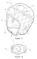
- FIG. 17 schematically illustrates a respiratory apparatus according to another sample embodiment
- FIG. 18 schematically illustrates a flow generator according to another sample embodiment
- FIGS. 19 and 20 schematically illustrate a respiratory apparatus incorporating the flow generator of FIG. 17 ;
- FIG. 21 schematically depicts a respiratory apparatus according to another sample embodiment.
- a respiratory apparatus for delivering a flow of pressurized breathable gas to a patient 2 for example to treat SBD, such as OSA, comprises a flow generator 4 to generate the flow of pressurized breathable gas.
- the flow generator 4 is contained in a flow generator housing or casing 6 that is anthropometrically configured to engage the head of the patient 2 .
- the flow generator housing 6 is configured to engage the top of the patient's head to permit the patient to sleep on the patient's side without disturbing the positioning of the flow generator housing 6 .
- the flow generator housing may have a curvature in the back to front direction of the housing, and a curvature in a lateral direction, i.e. in a direction from one side of the patient's head to the other side.
- the flow generator 4 delivers a flow of pressurized breathable gas through delivery tubes or conduits 8 which are connected to the flow generator housing 6 for receipt of the flow of pressurized breathable gas.
- the flow of pressurized breathable gas is delivered by the delivery conduits 8 , which extend from the flow generator housing 6 along the sides of the face of the patient 2 , to a patient interface 10 that is in contact with the nasal passageways of the patient 2 .
- the patient interface 10 may support nasal pillows or prongs 12 which are in sealing contact with the nares of the patient's nose.
- the delivery conduits 8 may deliver the flow of pressurized breathable gas to a nasal mask which covers only the nose of the patient.
- the delivery conduits 8 may be connected to a full face mask which covers the nose and mouth of the patient.
- the delivery conduits 8 may be connected to a patient interface that includes a mouth covering portion having nasal pillows or prongs extending from the mouth covering portion for sealing engagement with the nose of the patient.
- the patient interface may include nasal cannulae which do not sealingly engage with the nose of the patient.
- the conduits 8 may be formed of soft material, for example silicone rubber, to isolate vibrations from the flow generator 4 .
- the conduits 8 may also be connected to the flow generator by a connector configured to isolate vibrations, for example a soft grommet or a bellows type connector.
- the conduits 8 may also be the conduits as disclosed in U.S. Patent Application Publication 2008/0060649 A1, the entire contents being incorporated herein by reference.
- a respiratory apparatus includes strap attachment portions 14 provided on the delivery conduits 8 .
- a strap, or headgear system may be connected to the strap attachment portions to provide additional securement of the respiratory apparatus to the head of the patient.
- the flow generator housing 6 may be configured to extend towards the back of the head of the patient 2 , but may not extend as far forward on the head of the patient 2 as the flow generator housing 6 of the sample embodiment of FIG. 1 .
- the flow generator housing 6 may be configured to support a voltage regulator 16 , a motor controller 18 and a power source 20 .
- the power source 20 may comprise a battery, or a plurality of batteries.
- the battery or batteries may be configured as lithium polymer batteries having a volumetric energy density of about 250-530 Wh/L, for example about 270 to 400 Wh/l, as another example about 330 Wh/l and a gravimetric energy density of about 150-200 Wh/kg, for example about 155 to 175 Wh/kg, as another example about 163 Wh/kg.
- Such a battery would have, for example, a battery volume of 112 cm 2 and a weight of 225 g.
- the lithium polymer battery may comprise 32 lithium polymer battery cells that would provide approximately 8 hours of power to an electric motor of a blower assembly of the flow generator 4 for generating a flow of about 40-60 l/min, for example, 50 l/min at a pressure in a range of about 2-12 cm H 2 O, for example about 6 cm H 2 O.
- the battery cells may be flexible and thus may be curved for insertion into the housing 6 which may be curved to match the shape of the top of the patient's head.
- the lithium polymer battery may have a life cycle of approximately 500 charges.
- the flow generator housing 4 may be provided with a docking station configured to charge the battery when the housing 4 is placed in the station.
- the flow generator 4 comprises a blower assembly 22 .
- the blower assembly 22 comprises a blower assembly upper housing 24 and a blower assembly lower housing 34 .
- a blower assembly inlet 26 is provided in the upper housing 24 .
- the blower assembly 22 comprises a first outlet 28 and a second outlet 30 on opposite sides of the lower housing 34 .
- An electrical connector 32 is provided between the upper housing 24 and the lower housing 34 to provide power to an electric motor 44 ( FIG. 10 ).
- the blower assembly 22 comprises the upper housing 24 and the lower housing 34 and a middle housing 40 provided between the upper housing 24 and the lower housing 34 .
- a stator 38 is supported on the middle housing 40 .
- the electric motor 44 is supported by the stator 38 .
- the electric motor 44 includes a shaft 45 that extends from opposite sides of the electric motor 44 .
- the shaft 45 may be generally coincident with an axis of the motor 44 .
- a first impeller 36 is connected to the shaft 45 for rotation with the shaft upon actuation of the electric motor 44 .
- a second impeller 42 is connected to the opposite side of the shaft 45 and thus the opposite side of the motor for rotation with the shaft 45 upon actuation of the electric motor 44 .
- the motor 44 may be selected from a variety of commercially available motors, for example from the motors supplied by Maxon Motor of Switzerland.
- the shaft 45 rotates and causes rotation of the first impeller 36 and the second impeller 42 .
- rotation of the impellers 36 , 42 causes a flow F of air into the inlet 26 of the blower assembly 22 .
- the flow enters the upper housing 24 through the inlet 26 and proceeds around the first impeller 36 and is forced down towards the stator 38 .
- the flow then flows around the stator 38 and is forced down through the middle of the second housing 40 towards the second impeller 42 .
- the second impeller 42 forces the flow back up over the periphery of the middle housing 40 and out through the first outlet 28 and the second outlet 30 .
- the inlet 26 of the blower assembly 22 has an axis that is generally coincident with the axis of the electric motor 44 .
- the axis of the first outlet 28 and the axis of the second outlet 30 are generally tangential to circumference of the housings 24 , 34 and generally perpendicular to the axis of the blower assembly 22 and/or the motor 44 .
- the use of the axially coincident inlet 26 , the tangential outlets 28 , 30 , and the two impellers 36 , 42 provides a flow path that is folded back on itself, as shown in FIGS. 10 and 11 , which utilizes what would otherwise be dead space in the blower assembly and thus reduces the overall size of the blower assembly 22 .
- the reduced size of the blower assembly 22 provides smaller gaps and apertures along the flow path which reduces, or eliminates, turbulence and noise, and enables a low flow Reynolds number for the flow F from the blower assembly 22 .
- the blower assembly 22 may be adapted such that the path of the flow F extends along a first section from the inlet 26 having an axis that is generally parallel and/or coincident to the axis of the electric motor 44 . The flow F is then directed, along a second section, radially outwardly with regard to the axis of the electric motor 44 by the first impeller 36 .
- the flow F then extends along a third section, from the outer circumference of the first impeller 36 in a generally axial direction, and generally parallel and in the same general direction as the flow's initial direction when entering the inlet 26 along the first section.
- the flow F then extends, along a fourth section, radially inwardly along the stator 38 . Accordingly, the flow F is folded back on itself at least once, for example from a radial outward direction around the circumference of the first impeller 36 along the second section to a radial inward direction along the fourth section.
- the flow F extends radially inwardly along the stator 38 generally up to the outer circumference of the motor 44 .
- the flow F then extends along a fifth section that extends generally axially with respect to the axis of the motor 44 and along the motor in generally the same direction as the first section.
- the fifth section of the flow F may be defined between the motor 44 and the inner circumference of the middle housing 40 .
- the flow F then extends a long a sixth section and is directed radially outwardly with respect to the axis of the motor 44 by the second impeller 42 . Accordingly, the flow F is folded back on itself at least once, and possibly a second time, i.e.
- the flow F extends, along a seventh section, generally axially upwardly towards the first and/or second outlet 28 , 30 .
- the flow path F may be meandering. It should be appreciated that the description of the flow F relates to the cross sectional views shown in FIGS. 10 and 11 . As shown, the flow F may be generally radially symmetrical.
- the outlets 28 , 30 may be elliptical or oval.
- the use of elliptical or oval outlets reduces, or minimizes, the size of the outlets and allows the axial dimension, i.e. height, of the blower assembly 22 to be reduced, or minimized.
- the use of elliptical or oval outlets provides a sufficient cross sectional area to permit the flow to exit the blower assembly and also reduces sharp corners in the blower assembly.
- the use of two symmetrical outlets provides more outlet flow area for a given axial height than a single outlet, and lowers conducted noise. It should be appreciated that more than two outlets may be provided. It should also be appreciated that the outlets may have a 360° rotational symmetry.
- the first impeller 36 includes a first impeller disk 46 .
- a motor mounting portion 48 is configured for mounting the first impeller 36 to the electric motor shaft 45 .
- the motor mounting portion 48 includes an aperture 50 configured to receive the electric motor shaft 45 .
- a plurality of vanes 52 are provided on the first impeller disk 46 to generate the flow F upon rotation of the first impeller 36 .
- the vanes 52 direct the flow radially to the periphery of the first impeller 36 as shown in FIGS. 10 and 11 .
- the first impeller 36 generates a flow F that is initially in the axial direction of the electric motor 44 .
- the vanes 52 of the first impeller 36 are generally straight. However, it should be appreciated that the vanes 52 may be curved. As also shown in FIG. 13 , the vanes 52 may have a varying height. The height of the vanes may be largest toward the center of the first impeller disk 46 and may be smallest at the outer periphery or circumference of the first impeller disk 46 . The height of the vanes for 52 may be related to the diameter of the first impeller disk 46 for providing a desired flow. The height of the vanes 52 may be optimized for the selected diameter of the first impeller disk 46 to further reduce the overall size of the blower assembly 22 . The vanes 52 may be configured such that the height of the vanes 52 at their tips (i.e.
- the “choke” is related to the cylindrical surface of the disk 46 at the circumferential edge, i.e. the outer edges of the vanes 52 , and the axial height of the vanes 52 at the circumferential edge of the disk 46 .
- the “choke” is related to a cylinder of diameter equal to the outer diameter of disk 46 and which has an axial dimension (height) equal to the height of the vanes 52 at the periphery of disk 46 .
- the lower the height of the vanes 52 the lower the Reynolds number and therefore the lower the turbulence noise.
- the stator 38 comprises a stator disk 54 and a motor mounting portion 56 to mount the stator 38 to the electric motor 44 .
- a plurality of vanes 58 are provided on the stator disk 54 .
- the vanes 58 are curved to fold the flow F delivered from the first impeller 36 back towards the center of the blower assembly, i.e. back toward the electric motor 44 .
- the vanes 58 then direct the flow F in the direction of the axis of the electric motor 44 through the middle housing 40 toward the second impeller 42 , as shown in FIGS. 10 and 11 .
- the second impeller 42 comprises a second impeller disk 60 and a motor mounting portion 62 configured to connect the second impeller 42 to the shaft 45 of the electric motor 44 .
- a plurality of vanes 64 are provided on the second impeller disk 60 for directing the flow F around the middle housing 40 and out the first outlet 28 and a second outlet 30 , as shown in FIGS. 10 and 11 .
- the vanes 64 of the second impeller disk 60 may be configured in a manner similar to the vanes 52 of the first impeller disk 46 . As shown in FIGS. 9 b , 10 and 11 , the inner ends of the vanes 64 define a diameter that is larger than the diameter of the motor 44 . This allows the vanes 64 to sit, at least partly, at the same axial position as the lower section of the motor 44 , which reduces the axial height of the blower assembly 22 .
- the blower assembly may have a width of about 45-60 mm, for example about 50-55 mm, as another example about 52 mm, and a height of about 20-30 mm, for example about 23-27 mm, as another example about 25 mm.
- the motor may have a width of about 15-25 mm, for example about 17-23 mm, as another example about 20 mm, and a height of about 15-20 mm, for example about 17 mm.
- the motor may be brushless and deliver about 1-5 W shaft power, for example about 3 W.
- the motor may weigh about 10-20 g, for example about 13-17 g, as another example about 15 g.
- the blower assembly may provide a flow of about 40-60 l/min., for example about 45-55 l/min, as another example about 50 l/min., at a pressure of about 2-12 cm H 2 O, for example about 4-8 cm H 2 O, as another example about 6 cm H 2 O. It should be appreciated that these flow and pressure ranges are examples and the flow generator may be scaled to provide flow and pressure ranges other than the examples provided herein.
- the housing of the blower assembly may be configured to suppress noise generated by the motor 44 .
- a gel layer may be provided between the upper housing 24 and the lower housing 34 , and/or a gel layer may be provided between the stator 38 and the motor 44 to damp vibrations and/or noise generated by the motor 44 .
- blower assembly examples include providing bearings to the housing 24 , 34 instead of the motor 44 , as disclosed in U.S. Patent Application Publication 2008/0304986 A1, the entire contents of which are incorporated herein by reference, adding a magnet(s) to the impeller(s), and/or configuring the motor as an axial gap motor, for example as disclosed in WO 2007/134405 A1, the entire contents of which are incorporated herein by reference.
- flow generator and blower assemblies may be used in the sample embodiments discussed herein.
- the flow generator and blower assemblies disclosed in U.S. application Ser. Nos. 29/274,504, 29/274,505, and 29/274,506, each filed Apr. 27, 2007, and WO 2007/048206 A1, the entire contents of each being incorporated herein by reference, may be used.
- the flow generator and blower assemblies disclosed in U.S. application Ser. Nos. 29/274,504, 29/274,505, and 29/274,506, filed Apr. 27, 2007, 2006, and WO 2007/048205 A1 the entire contents of which are incorporated herein by reference, may be used.
- a respiratory apparatus comprises a flow generator 4 provided in a flow generator housing 6 configured to engage the head of the patient, for example the crown of the patient's head.
- the flow generator 4 is configured to deliver a flow of pressurized breathable gas to delivery conduits 8 which are configured to extend from the flow generator along the sides of the face of the patient to a patient interface 10 .
- the patient interface may include nasal pillows or prongs, a nasal mask, a full face mask, or cannulae.
- Power is provided to the flow generator 4 by a power supply and controller 66 that is connected to the flow generator 4 by an electrical connector 68 , for example a cable.
- the power supply/controller 66 may be configured to be docked in a battery charger, or may include an attachment that allows for charging of the power supply and controller from a voltage source, for example a common household 120 volt AC socket, or a 12 volt car battery charging outlet.
- a voltage source for example a common household 120 volt AC socket, or a 12 volt car battery charging outlet.
- a respiratory apparatus may comprise a headgear 80 that may take the form of, for example, a skull cap.
- a pair of ear covering portions 82 may be provided as well as a head covering portion 88 .
- a head circling band 90 may be provided between the ear covering portions 82 and the head covering portion 88 .
- a pair of straps, e.g. chin straps, 84 , 86 may be provided to the ear covering portions 82 to secure the headgear 80 to the patient.
- the flow generator may be provided in the headgear 80 , for example in the head covering portion 88 .
- the power supply e.g. the battery, or batteries, including the flexible cells
- the control electronics e.g. the voltage regulator and/or the motor controller
- the flow generator, the power supply and the control electronics may be encased in foam or other cushioning material to improve the comfort of the headgear.
- the battery cells may be distributed about the headgear 80 to spread the weight of the power supply throughout the headgear to improve comfort, reduce, or minimize the height of the apparatus, and increase, or maximize, the stability of the apparatus.
- a respiratory apparatus comprises a flow generator 4 comprising a flow generator housing or casing 6 .
- the flow generator 4 may include a blower assembly as previously described.
- the flow generator housing 6 comprises slots 70 configured to receive a band or strap 72 as shown in FIG. 18 .
- the band or strap 72 may be configured to encircle the chest or arm of the patient to support the flow generator 4 at a position spaced from the head of the patient.
- a delivery tube or conduit 74 is configured to be connected to the flow generator 4 at a first end and configured to be connected to a patient interface 10 at a second end.
- the delivery tube or conduit 74 may be a retractable tube or conduit that is flexible and extensible to accommodate movement of the patient's head, and thus movement of the patient interface 10 .
- a retractable tube is disclosed in U.S. application Ser. No. 12/211,896, filed Sep. 17, 2008, the entire content being incorporated herein by reference.
- the patient interface may be held in contact with the face of the patient by a headgear system 76 .
- the band, or strap, 92 may be configured to be integrally formed with the flow generator casing 6 .
- the band or strap may be separately formed and passed through the slots 70 in the flow generator casing 6 .
- the respiratory apparatus can be segmented into the respective elements.
- the power supply e.g. battery cells or pack
- the control electronics e.g. the voltage regulator and/or motor controller
- the left and/or right of the flow generator casing 6 may be located to the left and/or right of the flow generator casing 6 and connected by a flexible joint, such as a cable. This permits a more custom fit to the patient.
- the blower assembly housing may differ from the housing disclosed in FIGS. 4-16 in that the blower assembly housing may include a single outlet tangential to the blower assembly inlet. It should be appreciated, however, that the sample embodiment shown in FIGS. 18-20 may be provided with a pair of outlets, and a pair of delivery tubes or conduits which may deliver the flow of pressurized breathable gas to a patient interface having two inlets, for example an inlet on each side of the patient interface. Such a patient interface is disclosed, for example, in WO 2005/063328 A1, assigned to ResMed Ltd.
- the flow generator housing 6 may be configured to support the blower assembly 22 , the power source 20 , e.g. the battery or battery pack, and control circuitry for operation of the electric motor of the blower assembly.
- a variation of the sample embodiment of FIGS. 18-20 may include a concentric air inlet tube 78 surrounding the air delivery tube 74 . If the flow generator is worn beneath the patient's bed clothes, e.g. pajamas, the concentric air inlet tube may be placed outside the patient's bed clothes to draw fresh air into the flow generator housing.
- the flow generator may be turned on and off using a switch. It should also be appreciated that the flow generator may be turned on using ResMed's SMART START® control.
- the sample embodiments of the respiratory apparatus disclosed herein may be configured so that the noise level is sufficiently low to allow patients to sleep.
- typical flow generators are often configured such that the sound power emitted is about 25 dB based on testing 1 meter away at the front of the device.
- the sample embodiments of the respiratory apparatus disclosed herein are configured to be placed on the user's person, e.g. on the head, an arm, the chest. This proximity of the flow generator to the user may result in an increased sound level experienced by the user, for example by about 10 dB(A).
- the sample embodiments disclosed herein may include less insulation around the blower assembly of the flow generator, which may further increase the sound level experienced by the user, for example by about another 10 dB(A).
- a flow generator such as that disclosed in U.S. Patent Application Publication 2008/0304986 A1, the entire contents of which are incorporated herein by reference, comprising no insulation emits about 52 dB(A) sound power when running at 10 cm H 2 O air pressure.
- the sample embodiments of the respiratory apparatus disclosed herein may comprise insulating material within the headgear, mask, blower assembly, and/or flow generator casing, and/or a muffler, to reduce the sound power emitted.
- the headgear may be configured to reduce the sound power emitted by about 5-10 dB(A).
- the sample embodiments of the respiratory apparatus disclosed herein may emit a sound power of between about 10-100 dB(A), for example about 10-65 dB(A), as another example about 10-50 dB(A), as a further example about 20-40 dB(A), and as an even further example less than about 25 dB(A), when the respiratory apparatus is providing a flow at about 10 cm H 2 O.
- air will be taken to include breathable gases, for example air with supplemental oxygen. It is also acknowledged that the blowers described herein may be designed to pump fluids other than air.
- each individual component of any given assembly, one or more portions of an individual component of any given assembly, and various combinations of components from one or more embodiments may include one or more ornamental design features.
- the invention has particular application to patients who suffer from OSA, it is to be appreciated that patients who suffer from other illnesses (e.g., congestive heart failure, diabetes, morbid obesity, stroke, barriatric surgery, etc.) can derive benefit from the above teachings.
- the above teachings have applicability with patients and non-patients alike in non-medical applications.
Landscapes
- Health & Medical Sciences (AREA)
- Engineering & Computer Science (AREA)
- Pulmonology (AREA)
- Heart & Thoracic Surgery (AREA)
- Life Sciences & Earth Sciences (AREA)
- Veterinary Medicine (AREA)
- Anesthesiology (AREA)
- Biomedical Technology (AREA)
- Public Health (AREA)
- Hematology (AREA)
- Emergency Medicine (AREA)
- Animal Behavior & Ethology (AREA)
- General Health & Medical Sciences (AREA)
- Mechanical Engineering (AREA)
- General Engineering & Computer Science (AREA)
- Otolaryngology (AREA)
- Structures Of Non-Positive Displacement Pumps (AREA)
- Percussion Or Vibration Massage (AREA)
- Respiratory Apparatuses And Protective Means (AREA)
Priority Applications (5)
| Application Number | Priority Date | Filing Date | Title |
|---|---|---|---|
| US12/362,817 US8667962B2 (en) | 2008-01-31 | 2009-01-30 | Respiratory apparatus |
| US14/177,354 US9381318B2 (en) | 2008-01-31 | 2014-02-11 | Respiratory apparatus |
| US15/194,663 US10363385B2 (en) | 2008-01-31 | 2016-06-28 | Respiratory apparatus |
| US16/440,422 US11547820B2 (en) | 2008-01-31 | 2019-06-13 | Respiratory apparatus |
| US18/077,807 US20230108081A1 (en) | 2008-01-31 | 2022-12-08 | Respiratory apparatus |
Applications Claiming Priority (2)
| Application Number | Priority Date | Filing Date | Title |
|---|---|---|---|
| US2499308P | 2008-01-31 | 2008-01-31 | |
| US12/362,817 US8667962B2 (en) | 2008-01-31 | 2009-01-30 | Respiratory apparatus |
Related Child Applications (2)
| Application Number | Title | Priority Date | Filing Date |
|---|---|---|---|
| US14/177,354 Division US9381318B2 (en) | 2008-01-31 | 2014-02-11 | Respiratory apparatus |
| US14/177,354 Continuation US9381318B2 (en) | 2008-01-31 | 2014-02-11 | Respiratory apparatus |
Publications (2)
| Publication Number | Publication Date |
|---|---|
| US20090194101A1 US20090194101A1 (en) | 2009-08-06 |
| US8667962B2 true US8667962B2 (en) | 2014-03-11 |
Family
ID=40578040
Family Applications (5)
| Application Number | Title | Priority Date | Filing Date |
|---|---|---|---|
| US12/362,817 Active 2031-12-15 US8667962B2 (en) | 2008-01-31 | 2009-01-30 | Respiratory apparatus |
| US14/177,354 Active 2029-08-25 US9381318B2 (en) | 2008-01-31 | 2014-02-11 | Respiratory apparatus |
| US15/194,663 Active 2030-02-02 US10363385B2 (en) | 2008-01-31 | 2016-06-28 | Respiratory apparatus |
| US16/440,422 Active 2030-12-11 US11547820B2 (en) | 2008-01-31 | 2019-06-13 | Respiratory apparatus |
| US18/077,807 Pending US20230108081A1 (en) | 2008-01-31 | 2022-12-08 | Respiratory apparatus |
Family Applications After (4)
| Application Number | Title | Priority Date | Filing Date |
|---|---|---|---|
| US14/177,354 Active 2029-08-25 US9381318B2 (en) | 2008-01-31 | 2014-02-11 | Respiratory apparatus |
| US15/194,663 Active 2030-02-02 US10363385B2 (en) | 2008-01-31 | 2016-06-28 | Respiratory apparatus |
| US16/440,422 Active 2030-12-11 US11547820B2 (en) | 2008-01-31 | 2019-06-13 | Respiratory apparatus |
| US18/077,807 Pending US20230108081A1 (en) | 2008-01-31 | 2022-12-08 | Respiratory apparatus |
Country Status (6)
| Country | Link |
|---|---|
| US (5) | US8667962B2 (de) |
| EP (3) | EP3736005B1 (de) |
| JP (2) | JP5737827B2 (de) |
| CN (4) | CN104189979A (de) |
| AU (1) | AU2009200357B2 (de) |
| NZ (4) | NZ574584A (de) |
Cited By (9)
| Publication number | Priority date | Publication date | Assignee | Title |
|---|---|---|---|---|
| US20120167879A1 (en) * | 2011-01-03 | 2012-07-05 | Bowman Bruce R | Positive airway pressure therapy apparatus and methods |
| US20140137870A1 (en) * | 2011-06-21 | 2014-05-22 | Resmed Limited | Pap system |
| US20140158134A1 (en) * | 2008-01-31 | 2014-06-12 | Resmed Limited | Respiratory apparatus |
| US20150136140A1 (en) * | 2009-11-19 | 2015-05-21 | Resmed Motor Technologies Inc | Blower |
| US9694153B2 (en) | 2006-04-10 | 2017-07-04 | Somnetics Global Pte. Ltd. | Apparatus and methods for administration of positive airway pressure therapies |
| US10315001B2 (en) | 2015-03-03 | 2019-06-11 | Valley Children's Healthcare | Cranium cuddler |
| US10905837B2 (en) | 2015-04-02 | 2021-02-02 | Hill-Rom Services Pte. Ltd. | Respiratory therapy cycle control and feedback |
| US11167102B2 (en) | 2016-07-25 | 2021-11-09 | ResMed Pty Ltd | Respiratory pressure therapy system |
| US11338103B2 (en) | 2018-08-20 | 2022-05-24 | ResMed Pty Ltd | Headgear for a patient interface |
Families Citing this family (50)
| Publication number | Priority date | Publication date | Assignee | Title |
|---|---|---|---|---|
| WO2010080709A1 (en) | 2009-01-08 | 2010-07-15 | Hancock Medical | Self-contained, intermittent positive airway pressure systems and methods for treating sleep apnea, snoring, and other respiratory disorders |
| US10238822B2 (en) | 2009-05-29 | 2019-03-26 | Resmed Limited | PAP system |
| NZ598152A (en) | 2009-08-28 | 2014-02-28 | Resmed Ltd | Pap system |
| EP2490739A1 (de) * | 2009-10-20 | 2012-08-29 | Deshum Medical, LLC | Integrierte vorrichtung für positiven atemwegsdruck |
| EP2555849B1 (de) * | 2010-04-06 | 2018-06-27 | 3M Innovative Properties Company | Luftfiltergerät |
| EP2608835A4 (de) * | 2010-08-27 | 2018-03-28 | ResMed Limited | Pap-system |
| US8327846B2 (en) | 2011-02-08 | 2012-12-11 | Hancock Medical, Inc. | Positive airway pressure system with head position control |
| US20150128949A1 (en) * | 2011-02-11 | 2015-05-14 | Koninklijke Philips | Patient interface device having headgear providing integrated gas flow and delivery |
| WO2012113027A1 (en) * | 2011-02-25 | 2012-08-30 | Resmed Motor Technologies Inc. | Blower and pap system |
| FR2973846B1 (fr) * | 2011-04-11 | 2013-05-24 | Airfan | Appareil de delivrance regulee d'un gaz, notamment appareil d'assistance respiratoire |
| US9789273B2 (en) | 2011-05-13 | 2017-10-17 | Koninklijke Philips N.V. | Sensor and valve integrated into a patient interface |
| US10137264B2 (en) * | 2011-07-13 | 2018-11-27 | Fisher & Paykel Healthcare Limited | Respiratory assistance apparatus |
| US10286167B2 (en) | 2011-07-13 | 2019-05-14 | Fisher & Paykel Healthcare Limited | Impeller and motor assembly |
| US8873170B2 (en) | 2011-07-15 | 2014-10-28 | Honeywell International Inc. | Replacement lens cartridge |
| JP2013150684A (ja) * | 2012-01-25 | 2013-08-08 | Nidec Copal Electronics Corp | Cpap装置 |
| EP2817518B1 (de) | 2012-02-02 | 2020-05-20 | imtmedical ag | Schalldämmendes gehäuse für ein beatmungsgerät |
| EP3865169A1 (de) * | 2012-02-02 | 2021-08-18 | Fisher & Paykel Healthcare Limited | Atmungsunterstützungsvorrichtung |
| CN104394920B (zh) * | 2012-03-06 | 2017-03-01 | 瑞思迈发动机及马达技术股份有限公司 | 流量发生器 |
| CN102872511B (zh) * | 2012-10-03 | 2014-12-10 | 王秋华 | 微型鼻孔送风机 |
| US9192796B2 (en) | 2012-10-25 | 2015-11-24 | Honeywell International Inc. | Method of donning and testing abrasive blast respirator |
| US9192794B2 (en) | 2012-10-25 | 2015-11-24 | Honeywell International Inc. | Noise reduction system for supplied air respirator |
| US9162088B2 (en) | 2012-10-25 | 2015-10-20 | Honeywell International Inc. | Method of assembly and disassembly of abrasive blast respirator |
| US9192793B2 (en) | 2012-10-25 | 2015-11-24 | Honeywell International Inc. | Abrasive blast respirator |
| CA2893292A1 (en) * | 2012-12-14 | 2014-06-19 | Estill Medical Technologies, Inc. | Wearable in-line fluid warmer and battery combination |
| DE212013000256U1 (de) | 2012-12-18 | 2015-07-22 | Fisher & Paykel Healthcare Ltd. | Impeller und Rotor Baugruppe |
| US9289573B2 (en) | 2012-12-28 | 2016-03-22 | Covidien Lp | Ventilator pressure oscillation filter |
| CN103054708B (zh) * | 2013-01-11 | 2014-10-08 | 湖南纳雷科技有限公司 | 一种阻塞性睡眠呼吸暂停治疗仪 |
| WO2014117179A1 (en) | 2013-01-28 | 2014-07-31 | Hancock Medical, Inc. | Position control devices and methods for use with positive airway pressure systems |
| US20150306324A1 (en) * | 2014-04-29 | 2015-10-29 | Arturo Alejo Ayon | Self-contained continuous positive airway pressure mask and method of use |
| EP2942075A1 (de) * | 2014-05-07 | 2015-11-11 | Mindray Medical Sweden AB | Vorrichtung und Verfahren für ein Ventil mit geringem Widerstand |
| US10881829B2 (en) | 2014-08-18 | 2021-01-05 | Resmed Inc. | Portable pap device with humidification |
| CN107073237A (zh) * | 2014-11-19 | 2017-08-18 | 皇家飞利浦有限公司 | 用于患者接口的条带构件 |
| JP7188884B2 (ja) * | 2014-12-04 | 2022-12-13 | レスメド・プロプライエタリー・リミテッド | 空気送出用のウェラブルデバイス |
| CN104473710B (zh) * | 2015-01-05 | 2016-04-06 | 张希龙 | 磁悬浮下颌托止鼾器 |
| US10953188B2 (en) * | 2015-01-09 | 2021-03-23 | Fisher & Paykel Healthcare Limited | Gas therapy system |
| CN105879170A (zh) * | 2015-01-21 | 2016-08-24 | 深圳市沃森空调技术有限公司 | 可穿戴式智能增氧器 |
| USD776802S1 (en) | 2015-03-06 | 2017-01-17 | Hancock Medical, Inc. | Positive airway pressure system console |
| ES2585851B1 (es) * | 2015-04-07 | 2017-06-14 | Tecnicas Biomedicas Para La Salud, S.L. | Dispositivo impulsor de aire para proporcionar ventilación asistida durante la respiración espontánea |
| EP3365054B1 (de) * | 2015-10-23 | 2022-05-04 | Fisher & Paykel Healthcare Limited | Apparatus zur bereitstellung eines luftstroms an einen benutzer |
| CA3022511A1 (en) | 2016-05-04 | 2017-11-09 | Fisher & Paykel Healthcare Limited | Respiratory support system and blower for respiratory support system |
| JP6346914B2 (ja) * | 2016-05-13 | 2018-06-20 | アトムメディカル株式会社 | 呼吸用気体の供給装置 |
| JP2019518520A (ja) | 2016-05-19 | 2019-07-04 | ハンコック メディカル, インコーポレイテッド | 位置閉塞性睡眠時無呼吸検出システム |
| CN106247257A (zh) * | 2016-07-29 | 2016-12-21 | 辉能(天津)科技发展有限公司 | 一种智能医疗照明头灯 |
| CN111033067B (zh) | 2017-04-23 | 2022-01-14 | 费雪派克医疗保健有限公司 | 呼吸辅助设备 |
| DE102017007663B4 (de) | 2017-08-14 | 2022-12-29 | Rodenstock Gmbh | Verfahren und Vorrichtung zum Berechnen oder zum Bewerten eines Brillenglases für ein Auge eines Brillenträgers unter Berücksichtigung eines Visusmodells, entsprechendes Computerprogrammerzeugnis sowie Verfahren und Vorrichtung zum Herstellen eines Brillenglases |
| US11156224B2 (en) * | 2017-10-10 | 2021-10-26 | Tti (Macao Commercial Offshore) Limited | Backpack blower |
| JP6879432B2 (ja) * | 2018-03-30 | 2021-06-02 | 株式会社村田製作所 | Cpap装置 |
| CN116892526A (zh) * | 2020-05-15 | 2023-10-17 | 佛山市顺德区美的洗涤电器制造有限公司 | 离心风机及电器设备 |
| GB2597292B (en) * | 2020-07-20 | 2024-08-14 | Bae Systems Plc | Vibration decoupler |
| GB2622049A (en) * | 2022-08-31 | 2024-03-06 | Dyson Technology Ltd | A compressor and air purifier |
Citations (51)
| Publication number | Priority date | Publication date | Assignee | Title |
|---|---|---|---|---|
| US4233972A (en) | 1978-05-08 | 1980-11-18 | Wolfgang Hauff | Portable air filtering and breathing assist device |
| US4297999A (en) | 1979-07-19 | 1981-11-03 | Kitrell John V | Portable resuscitation apparatus |
| WO1982003548A1 (en) | 1981-04-24 | 1982-10-28 | Sullivan Colin Edward | Device for treating snoring sickness |
| EP0066451A1 (de) | 1981-05-29 | 1982-12-08 | Racal Safety Limited | Atemgerät mit motorunterstützter Luftreinigung |
| EP0164946A2 (de) | 1984-06-06 | 1985-12-18 | Racal Safety Limited | Athemschutzmasken |
| US4590951A (en) | 1983-06-07 | 1986-05-27 | Racal Safety Limited | Breathing apparatus |
| US4653976A (en) * | 1982-09-30 | 1987-03-31 | General Electric Company | Method of compressing a fluid flow in a multi stage centrifugal impeller |
| GB2209474A (en) | 1987-09-08 | 1989-05-17 | Chapman & Smith Limited | Respirators |
| GB2215216A (en) | 1988-03-01 | 1989-09-20 | Sabre Safety Ltd | Positive pressure breathing apparatus |
| EP0528733A1 (de) | 1991-08-21 | 1993-02-24 | Intertechnique | Giftstoffatemschutzausrüstung |
| US5303701A (en) | 1991-10-07 | 1994-04-19 | Dragerwerk Ag | Blower-supported gas mask and breathing equipment with an attachable control part |
| US5372130A (en) | 1992-02-26 | 1994-12-13 | Djs&T Limited Partnership | Face mask assembly and method having a fan and replaceable filter |
| US5538000A (en) | 1995-02-06 | 1996-07-23 | Hans Rudolph, Inc. | Airflow delivery system |
| WO1999013931A1 (en) | 1997-09-18 | 1999-03-25 | Caradyne (R & D) Limited | Portable respirator |
| US20020029777A1 (en) | 2000-09-12 | 2002-03-14 | Siegfried Zimprich | Apparatus for supplying respiratory gas to a parachute jumper |
| US6435184B1 (en) | 2000-09-01 | 2002-08-20 | Tien Lu Ho | Gas mask structure |
| US20020119044A1 (en) * | 2001-02-26 | 2002-08-29 | O'connor, John F. | Centrifugal blower with partitioned scroll diffuser |
| US6513526B2 (en) | 1996-07-26 | 2003-02-04 | Resmed Limited | Full-face mask and mask cushion therefor |
| US20030062045A1 (en) | 1998-09-18 | 2003-04-03 | Respironics, Inc. | Medical ventilator |
| US6561190B1 (en) | 1997-02-10 | 2003-05-13 | Resmed Limited | Mask and a vent assembly therefor |
| US6561191B1 (en) | 1997-02-10 | 2003-05-13 | Resmed Limited | Mask and a vent assembly therefor |
| EP1318307A1 (de) | 2001-12-10 | 2003-06-11 | Resmed Limited | Zweiseitiges Gebläse und Spiralgehäuse dazu |
| US20030172930A1 (en) | 2002-03-12 | 2003-09-18 | Gotz Kullik | Device for supporting respiration |
| US20040065330A1 (en) * | 2002-07-15 | 2004-04-08 | Landis Robert M. | Dynamic infant nasal CPAP system and method |
| US20040079373A1 (en) * | 2001-10-12 | 2004-04-29 | Yamamoto Kogaku Co., Ltd. | Respiration protecting apparatus |
| DE10261602A1 (de) | 2002-12-28 | 2004-07-08 | Yamamoto Kogaku Co., Ltd. | Atemschutzvorrichtung |
| US6772760B2 (en) | 2000-06-22 | 2004-08-10 | Resmed Limited | Mask with gusset |
| US6772762B2 (en) | 2000-05-24 | 2004-08-10 | Gregory Hubert Piesinger | Personal powered air filtration, sterilization, and conditioning system |
| US20040226562A1 (en) * | 2002-12-06 | 2004-11-18 | Bordewick Steven S. | Blower assembly for CPAP |
| WO2004108198A1 (en) | 2003-06-10 | 2004-12-16 | Resmed Limited | Multiple stage blower and enclosure therefor |
| US20050034724A1 (en) * | 1998-11-06 | 2005-02-17 | Caradyne (R&D) Limited | Apparatus and method for relieving dyspnoea |
| WO2005028009A1 (en) | 2003-09-25 | 2005-03-31 | Resmed Limited | Ventilator mask and system |
| US6889689B1 (en) | 2004-01-06 | 2005-05-10 | Deborah W. Neuman | Bubble CPAP cap for neonates |
| US20050103339A1 (en) * | 2001-12-10 | 2005-05-19 | Resmed Limited | Multiple stage blowers and volutes therefor |
| WO2005063328A1 (en) | 2003-12-31 | 2005-07-14 | Resmed Ltd | Compact oronasal patient interface |
| US20050217673A1 (en) * | 2001-12-10 | 2005-10-06 | Resmed Limited | Double-ended blower and volutes therefor |
| US20060096596A1 (en) | 2004-11-05 | 2006-05-11 | Occhialini James M | Wearable system for positive airway pressure therapy |
| US20060150973A1 (en) | 2003-07-04 | 2006-07-13 | Societe D'applications Industrielles | Breathing assistance device |
| US20070000493A1 (en) | 2005-06-01 | 2007-01-04 | Cox Kingsley J | Apparatus for maintaining airway patency |
| US20070089221A1 (en) * | 2005-08-09 | 2007-04-26 | Viasys Holdings, Inc. | Surgical protective head gear assembly including high volume air delivery system |
| WO2007048205A1 (en) | 2005-10-28 | 2007-05-03 | Resmed Ltd | Blower motor with flexible support sleeve |
| WO2007117716A2 (en) | 2006-04-10 | 2007-10-18 | Aeiomed, Inc. | Apparatus and methods for administration of positive airway pressure therapies |
| US20070251527A1 (en) | 2006-04-21 | 2007-11-01 | Tiara Medical Systems, Inc. | Self-contained respiratory therapy apparatus for enhanced patient compliance and therapeutic efficacy |
| WO2007134405A1 (en) | 2006-05-24 | 2007-11-29 | Resmed Ltd | Compact low noise efficient blower for cpap devices |
| US20080000474A1 (en) * | 2004-10-26 | 2008-01-03 | Map Medizin-Technologie Gmbh | Apparatus for Administering a Breathable Gas, and Components Thereof |
| US20080060649A1 (en) | 2006-07-28 | 2008-03-13 | Resmed Limited | Delivery of respiratory therapy |
| WO2008028247A1 (en) | 2006-09-07 | 2008-03-13 | Resmed Ltd | Mask and flow generator system |
| US20080216831A1 (en) | 2007-03-08 | 2008-09-11 | Mcginnis William J | Standalone cpap device and method of using |
| US20080216833A1 (en) * | 2007-03-07 | 2008-09-11 | Pujol J Raymond | Flow Sensing for Gas Delivery to a Patient |
| US20080304986A1 (en) | 2007-06-05 | 2008-12-11 | Resmed Limited | Blower with bearing tube |
| US7748381B2 (en) * | 2005-12-09 | 2010-07-06 | 3M Innovative Properties Company | Portable blower system |
Family Cites Families (17)
| Publication number | Priority date | Publication date | Assignee | Title |
|---|---|---|---|---|
| US3822698A (en) * | 1973-01-22 | 1974-07-09 | R Guy | Powered air-purifying respirator helmet |
| JPS5470108U (de) * | 1977-10-28 | 1979-05-18 | ||
| JPS5849186B2 (ja) | 1977-11-14 | 1983-11-02 | 株式会社片岡機械製作所 | グラビア輪転印刷機の版胴支持装置 |
| JP3475174B2 (ja) * | 2000-02-10 | 2003-12-08 | 東芝テック株式会社 | 電動ポンプ |
| JP2004019605A (ja) * | 2002-06-19 | 2004-01-22 | Matsushita Electric Ind Co Ltd | 流体輸送システム及びその方法 |
| EP1558321B1 (de) * | 2002-11-06 | 2016-07-13 | ResMed Limited | Maske und ihre bestandteile |
| CN101496926B (zh) * | 2003-02-21 | 2015-01-21 | 瑞思迈有限公司 | 鼻组件 |
| AU2003903139A0 (en) * | 2003-06-20 | 2003-07-03 | Resmed Limited | Breathable gas apparatus with humidifier |
| JP2005171825A (ja) * | 2003-12-09 | 2005-06-30 | Ebara Corp | 流体搬送機械 |
| GB0402625D0 (en) * | 2004-02-06 | 2004-03-10 | Boc Group Plc | Vibration damper |
| JP4592314B2 (ja) | 2004-03-26 | 2010-12-01 | 株式会社東芝 | 流体ポンプ及び電気機器並びに冷却装置 |
| DE102005031388B4 (de) * | 2005-07-05 | 2017-05-04 | Resmed Limited | Vorrichtung zur Förderung eines Atemgases |
| JP2007078259A (ja) | 2005-09-14 | 2007-03-29 | Japan Vilene Co Ltd | ファンフィルタユニット |
| US7516743B2 (en) * | 2006-04-20 | 2009-04-14 | Viasys Sleep Systems, Llc | Continuous positive airway pressure device and configuration for employing same |
| EP2051760B1 (de) * | 2006-07-28 | 2014-03-12 | ResMed Limited | Patientenschnittstelle |
| EP3736005B1 (de) | 2008-01-31 | 2024-02-28 | ResMed Pty Ltd | Beatmungsgerät |
| US10137264B2 (en) * | 2011-07-13 | 2018-11-27 | Fisher & Paykel Healthcare Limited | Respiratory assistance apparatus |
-
2009
- 2009-01-30 EP EP20170508.4A patent/EP3736005B1/de active Active
- 2009-01-30 NZ NZ574584A patent/NZ574584A/en unknown
- 2009-01-30 NZ NZ602818A patent/NZ602818A/en unknown
- 2009-01-30 EP EP09001343.4A patent/EP2085106B1/de active Active
- 2009-01-30 US US12/362,817 patent/US8667962B2/en active Active
- 2009-01-30 EP EP17181906.3A patent/EP3305353B1/de active Active
- 2009-01-30 JP JP2009020018A patent/JP5737827B2/ja active Active
- 2009-01-30 NZ NZ593449A patent/NZ593449A/xx unknown
- 2009-01-30 AU AU2009200357A patent/AU2009200357B2/en not_active Ceased
- 2009-01-30 NZ NZ585029A patent/NZ585029A/en unknown
- 2009-02-01 CN CN201410466771.XA patent/CN104189979A/zh active Pending
- 2009-02-01 CN CN202011145319.5A patent/CN112535786B/zh active Active
- 2009-02-01 CN CN200910126785.6A patent/CN101502690B/zh active Active
- 2009-02-01 CN CN201710403961.0A patent/CN107261271B/zh active Active
-
2014
- 2014-02-11 US US14/177,354 patent/US9381318B2/en active Active
- 2014-04-07 JP JP2014078423A patent/JP6161564B2/ja active Active
-
2016
- 2016-06-28 US US15/194,663 patent/US10363385B2/en active Active
-
2019
- 2019-06-13 US US16/440,422 patent/US11547820B2/en active Active
-
2022
- 2022-12-08 US US18/077,807 patent/US20230108081A1/en active Pending
Patent Citations (59)
| Publication number | Priority date | Publication date | Assignee | Title |
|---|---|---|---|---|
| US4233972A (en) | 1978-05-08 | 1980-11-18 | Wolfgang Hauff | Portable air filtering and breathing assist device |
| US4297999A (en) | 1979-07-19 | 1981-11-03 | Kitrell John V | Portable resuscitation apparatus |
| WO1982003548A1 (en) | 1981-04-24 | 1982-10-28 | Sullivan Colin Edward | Device for treating snoring sickness |
| JPS58500551A (ja) | 1981-04-24 | 1983-04-14 | ソメド プテイ.リミテツド | 鼻マスクのエア供給装置 |
| EP0066451A1 (de) | 1981-05-29 | 1982-12-08 | Racal Safety Limited | Atemgerät mit motorunterstützter Luftreinigung |
| US4653976A (en) * | 1982-09-30 | 1987-03-31 | General Electric Company | Method of compressing a fluid flow in a multi stage centrifugal impeller |
| US4590951A (en) | 1983-06-07 | 1986-05-27 | Racal Safety Limited | Breathing apparatus |
| EP0164946A2 (de) | 1984-06-06 | 1985-12-18 | Racal Safety Limited | Athemschutzmasken |
| GB2209474A (en) | 1987-09-08 | 1989-05-17 | Chapman & Smith Limited | Respirators |
| GB2215216A (en) | 1988-03-01 | 1989-09-20 | Sabre Safety Ltd | Positive pressure breathing apparatus |
| EP0528733A1 (de) | 1991-08-21 | 1993-02-24 | Intertechnique | Giftstoffatemschutzausrüstung |
| US5318020A (en) | 1991-08-21 | 1994-06-07 | Intertechnique | Equipment for respiratory protection against pollutants |
| US5303701A (en) | 1991-10-07 | 1994-04-19 | Dragerwerk Ag | Blower-supported gas mask and breathing equipment with an attachable control part |
| US5372130A (en) | 1992-02-26 | 1994-12-13 | Djs&T Limited Partnership | Face mask assembly and method having a fan and replaceable filter |
| US5538000A (en) | 1995-02-06 | 1996-07-23 | Hans Rudolph, Inc. | Airflow delivery system |
| US6513526B2 (en) | 1996-07-26 | 2003-02-04 | Resmed Limited | Full-face mask and mask cushion therefor |
| US6561191B1 (en) | 1997-02-10 | 2003-05-13 | Resmed Limited | Mask and a vent assembly therefor |
| US6561190B1 (en) | 1997-02-10 | 2003-05-13 | Resmed Limited | Mask and a vent assembly therefor |
| WO1999013931A1 (en) | 1997-09-18 | 1999-03-25 | Caradyne (R & D) Limited | Portable respirator |
| US20030062045A1 (en) | 1998-09-18 | 2003-04-03 | Respironics, Inc. | Medical ventilator |
| US20050034724A1 (en) * | 1998-11-06 | 2005-02-17 | Caradyne (R&D) Limited | Apparatus and method for relieving dyspnoea |
| US6772762B2 (en) | 2000-05-24 | 2004-08-10 | Gregory Hubert Piesinger | Personal powered air filtration, sterilization, and conditioning system |
| US6772760B2 (en) | 2000-06-22 | 2004-08-10 | Resmed Limited | Mask with gusset |
| US6435184B1 (en) | 2000-09-01 | 2002-08-20 | Tien Lu Ho | Gas mask structure |
| US20020029777A1 (en) | 2000-09-12 | 2002-03-14 | Siegfried Zimprich | Apparatus for supplying respiratory gas to a parachute jumper |
| US20020119044A1 (en) * | 2001-02-26 | 2002-08-29 | O'connor, John F. | Centrifugal blower with partitioned scroll diffuser |
| US20040079373A1 (en) * | 2001-10-12 | 2004-04-29 | Yamamoto Kogaku Co., Ltd. | Respiration protecting apparatus |
| US20050103339A1 (en) * | 2001-12-10 | 2005-05-19 | Resmed Limited | Multiple stage blowers and volutes therefor |
| EP1318307A1 (de) | 2001-12-10 | 2003-06-11 | Resmed Limited | Zweiseitiges Gebläse und Spiralgehäuse dazu |
| US20050217673A1 (en) * | 2001-12-10 | 2005-10-06 | Resmed Limited | Double-ended blower and volutes therefor |
| US20030172930A1 (en) | 2002-03-12 | 2003-09-18 | Gotz Kullik | Device for supporting respiration |
| US6895962B2 (en) | 2002-03-12 | 2005-05-24 | Dräger Medical AG & Co. KGaA | Device for supporting respiration |
| US20040065330A1 (en) * | 2002-07-15 | 2004-04-08 | Landis Robert M. | Dynamic infant nasal CPAP system and method |
| US20040226562A1 (en) * | 2002-12-06 | 2004-11-18 | Bordewick Steven S. | Blower assembly for CPAP |
| DE10261602A1 (de) | 2002-12-28 | 2004-07-08 | Yamamoto Kogaku Co., Ltd. | Atemschutzvorrichtung |
| CN1805766A (zh) | 2003-06-10 | 2006-07-19 | 雷斯梅德有限公司 | 多级吹风机及其外壳 |
| WO2004108198A1 (en) | 2003-06-10 | 2004-12-16 | Resmed Limited | Multiple stage blower and enclosure therefor |
| US20060150973A1 (en) | 2003-07-04 | 2006-07-13 | Societe D'applications Industrielles | Breathing assistance device |
| WO2005028009A1 (en) | 2003-09-25 | 2005-03-31 | Resmed Limited | Ventilator mask and system |
| US20060237013A1 (en) | 2003-09-25 | 2006-10-26 | Kwok Philip R | Ventilator mask and system |
| CN1859940A (zh) | 2003-09-25 | 2006-11-08 | 雷斯梅德有限公司 | 呼吸机面罩及其系统 |
| WO2005063328A1 (en) | 2003-12-31 | 2005-07-14 | Resmed Ltd | Compact oronasal patient interface |
| US6889689B1 (en) | 2004-01-06 | 2005-05-10 | Deborah W. Neuman | Bubble CPAP cap for neonates |
| US20080000474A1 (en) * | 2004-10-26 | 2008-01-03 | Map Medizin-Technologie Gmbh | Apparatus for Administering a Breathable Gas, and Components Thereof |
| US20060096596A1 (en) | 2004-11-05 | 2006-05-11 | Occhialini James M | Wearable system for positive airway pressure therapy |
| US20070000493A1 (en) | 2005-06-01 | 2007-01-04 | Cox Kingsley J | Apparatus for maintaining airway patency |
| US20070089221A1 (en) * | 2005-08-09 | 2007-04-26 | Viasys Holdings, Inc. | Surgical protective head gear assembly including high volume air delivery system |
| WO2007048205A1 (en) | 2005-10-28 | 2007-05-03 | Resmed Ltd | Blower motor with flexible support sleeve |
| WO2007048206A1 (en) | 2005-10-28 | 2007-05-03 | Resmed Ltd | Single or multiple stage blower and nested volute(s) and/or impeller(s) therefor |
| US7748381B2 (en) * | 2005-12-09 | 2010-07-06 | 3M Innovative Properties Company | Portable blower system |
| WO2007117716A2 (en) | 2006-04-10 | 2007-10-18 | Aeiomed, Inc. | Apparatus and methods for administration of positive airway pressure therapies |
| US20070277827A1 (en) * | 2006-04-10 | 2007-12-06 | Bordewick Steven S | Apparatus and methods for administration of positive airway pressure therapies |
| US20070251527A1 (en) | 2006-04-21 | 2007-11-01 | Tiara Medical Systems, Inc. | Self-contained respiratory therapy apparatus for enhanced patient compliance and therapeutic efficacy |
| WO2007134405A1 (en) | 2006-05-24 | 2007-11-29 | Resmed Ltd | Compact low noise efficient blower for cpap devices |
| US20080060649A1 (en) | 2006-07-28 | 2008-03-13 | Resmed Limited | Delivery of respiratory therapy |
| WO2008028247A1 (en) | 2006-09-07 | 2008-03-13 | Resmed Ltd | Mask and flow generator system |
| US20080216833A1 (en) * | 2007-03-07 | 2008-09-11 | Pujol J Raymond | Flow Sensing for Gas Delivery to a Patient |
| US20080216831A1 (en) | 2007-03-08 | 2008-09-11 | Mcginnis William J | Standalone cpap device and method of using |
| US20080304986A1 (en) | 2007-06-05 | 2008-12-11 | Resmed Limited | Blower with bearing tube |
Non-Patent Citations (12)
| Title |
|---|
| Extended European Search Report mailed May 20, 2009 in European Application No. 09001343.4. |
| Notice of Reasons for Rejection mailed Jan. 7, 2014 in Japanese Application No. 2009-020018, with English Translation (7 pages). |
| Notice of Reasons for Rejection mailed Mar. 19, 2013 in Japanese Application No. 2009-020018, with English translation (9 pages). |
| Notification of First Office Action mailed Aug. 2, 2012 in Chinese Application No. 200910126785.6, with English Translation (14 pages). |
| Notification of the Second Office Action issued Apr. 19, 2013 in Chinese Application No. 200910126785.6, with English Translation (14 pages). |
| Notification of the Third Office Action mailed Nov. 5, 2013 in Chinese Application No. 200910126785.6, with English Translation (13 pages). |
| Patent Examination Report No. 1 issued Jan. 31, 2013 in Australian Application No. 2009200357 (3 pages). |
| Patent Examination Report No. 2 issued Aug. 28, 2013 in Australian Application No. 2009200357 (3 pages). |
| U.S. Appl. No. 29/274,504, filed Apr. 2007, Kenyon. |
| U.S. Appl. No. 29/274,505, filed Apr. 2007, Kenyon. |
| U.S. Appl. No. 29/274,506, filed Apr. 2007, Kenyon. |
| U.S. Appl. No. 60/494,119, filed Aug. 2003, Gunaratnam et al. |
Cited By (19)
| Publication number | Priority date | Publication date | Assignee | Title |
|---|---|---|---|---|
| US9694153B2 (en) | 2006-04-10 | 2017-07-04 | Somnetics Global Pte. Ltd. | Apparatus and methods for administration of positive airway pressure therapies |
| US11547820B2 (en) | 2008-01-31 | 2023-01-10 | ResMed Pty Ltd | Respiratory apparatus |
| US20140158134A1 (en) * | 2008-01-31 | 2014-06-12 | Resmed Limited | Respiratory apparatus |
| US10363385B2 (en) * | 2008-01-31 | 2019-07-30 | ResMed Pty Ltd | Respiratory apparatus |
| US9381318B2 (en) * | 2008-01-31 | 2016-07-05 | Resmed Limited | Respiratory apparatus |
| US10940280B2 (en) | 2009-11-19 | 2021-03-09 | Resmed Motor Technologies Inc. | Blower |
| US20150136140A1 (en) * | 2009-11-19 | 2015-05-21 | Resmed Motor Technologies Inc | Blower |
| US9662463B2 (en) * | 2009-11-19 | 2017-05-30 | Resmed Motor Technologies Inc. | Blower |
| US20120167879A1 (en) * | 2011-01-03 | 2012-07-05 | Bowman Bruce R | Positive airway pressure therapy apparatus and methods |
| US9993605B2 (en) * | 2011-06-21 | 2018-06-12 | Resmed Limited | PAP system |
| US10973999B2 (en) | 2011-06-21 | 2021-04-13 | ResMed Pty Ltd | PAP system |
| US20140137870A1 (en) * | 2011-06-21 | 2014-05-22 | Resmed Limited | Pap system |
| US10315001B2 (en) | 2015-03-03 | 2019-06-11 | Valley Children's Healthcare | Cranium cuddler |
| US10905837B2 (en) | 2015-04-02 | 2021-02-02 | Hill-Rom Services Pte. Ltd. | Respiratory therapy cycle control and feedback |
| US10905836B2 (en) | 2015-04-02 | 2021-02-02 | Hill-Rom Services Pte. Ltd. | Manifold for respiratory device |
| US11992611B2 (en) | 2015-04-02 | 2024-05-28 | Hill-Rom Services Pte. Ltd. | Respiratory therapy apparatus control |
| US11167102B2 (en) | 2016-07-25 | 2021-11-09 | ResMed Pty Ltd | Respiratory pressure therapy system |
| US12029850B2 (en) | 2016-07-25 | 2024-07-09 | ResMed Pty Ltd | Respiratory pressure therapy system |
| US11338103B2 (en) | 2018-08-20 | 2022-05-24 | ResMed Pty Ltd | Headgear for a patient interface |
Also Published As
| Publication number | Publication date |
|---|---|
| US20140158134A1 (en) | 2014-06-12 |
| US20200129715A1 (en) | 2020-04-30 |
| EP3305353B1 (de) | 2020-04-22 |
| CN107261271A (zh) | 2017-10-20 |
| EP2085106A1 (de) | 2009-08-05 |
| US20160303338A1 (en) | 2016-10-20 |
| EP3736005A1 (de) | 2020-11-11 |
| NZ585029A (en) | 2011-07-29 |
| EP3736005B1 (de) | 2024-02-28 |
| US9381318B2 (en) | 2016-07-05 |
| CN112535786B (zh) | 2024-07-12 |
| US20230108081A1 (en) | 2023-04-06 |
| CN101502690A (zh) | 2009-08-12 |
| CN112535786A (zh) | 2021-03-23 |
| NZ593449A (en) | 2012-12-21 |
| NZ574584A (en) | 2010-10-29 |
| CN104189979A (zh) | 2014-12-10 |
| AU2009200357A1 (en) | 2009-08-20 |
| JP2014133166A (ja) | 2014-07-24 |
| JP5737827B2 (ja) | 2015-06-17 |
| EP2085106B1 (de) | 2017-07-19 |
| US11547820B2 (en) | 2023-01-10 |
| US20090194101A1 (en) | 2009-08-06 |
| AU2009200357B2 (en) | 2013-10-24 |
| NZ602818A (en) | 2014-01-31 |
| US10363385B2 (en) | 2019-07-30 |
| EP3305353A1 (de) | 2018-04-11 |
| JP2009178557A (ja) | 2009-08-13 |
| CN101502690B (zh) | 2016-08-24 |
| CN107261271B (zh) | 2020-11-10 |
| JP6161564B2 (ja) | 2017-07-12 |
Similar Documents
| Publication | Publication Date | Title |
|---|---|---|
| US20230108081A1 (en) | Respiratory apparatus | |
| US20240277958A1 (en) | Single stage, axial symmetric blower and portable ventilator | |
| JP6220349B2 (ja) | 呼吸補助装置 | |
| JP7032310B2 (ja) | 使用者に空気流を提供する装置 | |
| AU2014200366B2 (en) | Respiratory Apparatus |
Legal Events
| Date | Code | Title | Description |
|---|---|---|---|
| AS | Assignment |
Owner name: RESMED LIMITED, AUSTRALIA Free format text: ASSIGNMENT OF ASSIGNORS INTEREST;ASSIGNORS:KENYON, BARTON JOHN;DOHERTY, RENEE FRANCES;BRAMBILLA, ENRICO;AND OTHERS;REEL/FRAME:022294/0430;SIGNING DATES FROM 20090203 TO 20090204 Owner name: RESMED LIMITED, AUSTRALIA Free format text: ASSIGNMENT OF ASSIGNORS INTEREST;ASSIGNORS:KENYON, BARTON JOHN;DOHERTY, RENEE FRANCES;BRAMBILLA, ENRICO;AND OTHERS;SIGNING DATES FROM 20090203 TO 20090204;REEL/FRAME:022294/0430 |
|
| FEPP | Fee payment procedure |
Free format text: PAYOR NUMBER ASSIGNED (ORIGINAL EVENT CODE: ASPN); ENTITY STATUS OF PATENT OWNER: LARGE ENTITY |
|
| STCF | Information on status: patent grant |
Free format text: PATENTED CASE |
|
| MAFP | Maintenance fee payment |
Free format text: PAYMENT OF MAINTENANCE FEE, 4TH YEAR, LARGE ENTITY (ORIGINAL EVENT CODE: M1551) Year of fee payment: 4 |
|
| AS | Assignment |
Owner name: RESMED PTY LTD, AUSTRALIA Free format text: CHANGE OF NAME;ASSIGNOR:RESMED LIMITED;REEL/FRAME:050005/0461 Effective date: 20190301 |
|
| MAFP | Maintenance fee payment |
Free format text: PAYMENT OF MAINTENANCE FEE, 8TH YEAR, LARGE ENTITY (ORIGINAL EVENT CODE: M1552); ENTITY STATUS OF PATENT OWNER: LARGE ENTITY Year of fee payment: 8 |