US8649005B2 - Optical flow cell detector - Google Patents
Optical flow cell detector Download PDFInfo
- Publication number
- US8649005B2 US8649005B2 US13/522,880 US201113522880A US8649005B2 US 8649005 B2 US8649005 B2 US 8649005B2 US 201113522880 A US201113522880 A US 201113522880A US 8649005 B2 US8649005 B2 US 8649005B2
- Authority
- US
- United States
- Prior art keywords
- flow cell
- detector
- light guide
- light
- optical
- Prior art date
- Legal status (The legal status is an assumption and is not a legal conclusion. Google has not performed a legal analysis and makes no representation as to the accuracy of the status listed.)
- Active
Links
Images


Classifications
-
- G—PHYSICS
- G01—MEASURING; TESTING
- G01N—INVESTIGATING OR ANALYSING MATERIALS BY DETERMINING THEIR CHEMICAL OR PHYSICAL PROPERTIES
- G01N21/00—Investigating or analysing materials by the use of optical means, i.e. using sub-millimetre waves, infrared, visible or ultraviolet light
- G01N21/01—Arrangements or apparatus for facilitating the optical investigation
- G01N21/03—Cuvette constructions
- G01N21/05—Flow-through cuvettes
-
- G—PHYSICS
- G01—MEASURING; TESTING
- G01N—INVESTIGATING OR ANALYSING MATERIALS BY DETERMINING THEIR CHEMICAL OR PHYSICAL PROPERTIES
- G01N21/00—Investigating or analysing materials by the use of optical means, i.e. using sub-millimetre waves, infrared, visible or ultraviolet light
- G01N21/01—Arrangements or apparatus for facilitating the optical investigation
- G01N21/03—Cuvette constructions
- G01N2021/0346—Capillary cells; Microcells
-
- G—PHYSICS
- G01—MEASURING; TESTING
- G01N—INVESTIGATING OR ANALYSING MATERIALS BY DETERMINING THEIR CHEMICAL OR PHYSICAL PROPERTIES
- G01N21/00—Investigating or analysing materials by the use of optical means, i.e. using sub-millimetre waves, infrared, visible or ultraviolet light
- G01N21/01—Arrangements or apparatus for facilitating the optical investigation
- G01N21/03—Cuvette constructions
- G01N21/0303—Optical path conditioning in cuvettes, e.g. windows; adapted optical elements or systems; path modifying or adjustment
-
- G—PHYSICS
- G01—MEASURING; TESTING
- G01N—INVESTIGATING OR ANALYSING MATERIALS BY DETERMINING THEIR CHEMICAL OR PHYSICAL PROPERTIES
- G01N2201/00—Features of devices classified in G01N21/00
- G01N2201/08—Optical fibres; light guides
Definitions
- the present disclosure relates to an optical flow cell detector, and a flow cell absorption monitor system comprising such a sensor.
- a flow cell absorption monitor system typically comprises a light source for providing light of one or more wavelengths to a fluid sample in a fluid cell and an optical detection system for detecting any interaction between the light and the sample.
- a flow cell absorption monitor system is a flow cell UV absorption monitor system that is utilized to measure different absorbance of light at various wavelengths in chromatography systems when separated molecules are eluted from the columns.
- Monitor systems of this type usually include a light source, a flow cell and a light detector.
- the flow cell is designed to ensure a signal-to-noise ratio with minimal drift and refractive index sensitivity.
- the object of the invention is to provide a new optical flow cell detector and a flow cell absorption monitor system using the same, which overcomes one or more drawbacks of the prior art. This is achieved by the optical flow cell detector and the flow cell absorption monitor system as defined in the independent claim.
- optical flow cell detector is that it is capable of registering high protein concentrations in a flow through mode, and with an essentially linear response.
- the detector may be arranged in the main flow channel as it may be designed such that the cross sectional flow area is essentially uniform in the flow direction throughout the flow cell.
- FIG. 1 illustrates a schematic of a typical flow cell absorption monitor system
- FIGS. 2A to 2C show a schematic optical flow cell detector in accordance with an embodiment of the invention
- FIGS. 3A to 3C show a schematic optical flow cell detector in accordance with an embodiment of the invention
- FIG. 4 shows a schematic embodiment of an integrated flow cell absorption monitor system with an optical flow cell detector in accordance with an embodiment of the invention
- FIG. 5 shows a schematic optical flow cell dual detector in accordance with an embodiment of the invention
- FIG. 6 shows a schematic UV absorption graph for an optical flow cell detector in accordance with an embodiment of the invention, in comparison with a schematic graph for a prior art wide gap detector;
- FIG. 7 is an experimental graph showing the linearity of a optical flow cell detector in accordance with an embodiment of the invention.
- FIG. 8 is an experimental graph showing the linearity of a optical flow cell detector in accordance with an embodiment of the invention in comparison with a prior art wide gap detector;
- FIG. 1 illustrates a one embodiment of a flow cell absorption monitor system, such as a multi-wavelength Ultra-violet (UV)-Visible monitor.
- This monitor 101 includes an interchangeable flow cell 103 and optical fibers 105 connecting the flow cell to the monitor unit 101 .
- Monitor 101 may e.g. be a Monitor UV-900 manufactured by GE Healthcare, Life Sciences located in Uppsala, Sweden.
- This monitor utilizes advanced fiber optic technology to monitor light with high sensitivity at up to three wavelengths simultaneously in a range of 190-700 nm.
- the use of fiber optics together with the unique flow cell design ensures a signal-to-noise ratio with minimal drift and refractive index sensitivity.
- the monitor 101 includes a monochromator 107 with a light source (not shown), such as a xenon flash lamp (not shown) that provides a high intensity, continuous spectrum of light, and a tuneable monochromator arrangement (not shown) for selecting the wavelength of light output to the fiber 105 .
- a light source such as a xenon flash lamp (not shown) that provides a high intensity, continuous spectrum of light
- a tuneable monochromator arrangement (not shown) for selecting the wavelength of light output to the fiber 105 .
- the lamp is activated only during the chromatographic run, ensuring that its long lifetime of approximately 4000 hours of effective operation is used efficiently.
- the tuneable monochromator may be any suitable type, capable of providing the desired wavelength range, or even two or more units with complementary wavelength ranges.
- the tuneable monochromator is a tuneable laser unit capable of providing monochromatic light over a specified range.
- the tuneable monochromator when tuneability is of less importance, may be substituted by one or more discrete monochromatic light sources.
- the monochromator is replaced by a broad band light source, and a light detection unit 115 is e.g a spectrometer capable of spectroscopiaclly dividing the received spectra.
- the optical fiber 105 optics leads the light from the monochromator 107 to an optical splitter unit 109 splitting the light to a reference fiber 111 and a flow cell fiber 113 leading directly to the flow cell 103 and focus its full intensity on the liquid flow path, thus maximizing the sensitivity of the monitoring.
- Flow cell 103 may have any path length, such as a path length of 2 mm and cell volume of 2 ⁇ l or path length of 10 mm and a cell volume of 8 ⁇ l.
- the transmitted light through the flow cell 103 is guided to a light detection unit 115 via an optical fiber 121 .
- the light detection unit 115 has a flow cell input 119 connected to fiber 121 and a reference input 117 connected to the reference fiber 111 .
- the detection unit 115 further may comprise suitable processing means for comparing the flow cell input with the reference to detect changes in light absorption in the flow cell.
- FIGS. 2A and 2B show a schematic optical flow cell detector 200 in accordance with an embodiment of the invention.
- the optical flow cell detector 200 comprises a detector body 205 with a sample inlet 210 and outlet 220 in fluidic communication through a flow cell channel 230 of cross sectional area A.
- the flow cell channel 230 may essentially be of any cross sectional area A as required for the specific application where it is to be used, depending on factors as flow rate, viscosity etc.
- the cross sectional shape is circular which is beneficial from a manufacturing point of view as well as a fluid flow point of view, but it may actually be of essentially any suitable shape as long as the fluid flow characteristics are preserved within the desired range.
- the detection optics is comprised of an input light guide 240 with a light exit surface 250 arranged adjacent and in optical alignment with a light entrance 260 surface of an output light guide 270 .
- the input light guide 240 and the output light guide 270 protrudes into the flow cell channel 230 so that the optical gap between the light exit surface 250 and the light entrance surface 260 is situated centrally in the flow cell channel 230 .
- the optical gap may e.g. be situated at any position in the flow cell channel 230 as long as it is not located in a stagnant zone, e.g. adjacent a wall of the channel in order to ensure that the fluid in the gap is representative of the fluid flow.
- the input light guide 240 and the output light guide 270 protrudes essentially transverse into the flow cell channel 230 , whereby exchange of fluid in the optical gap is promoted.
- the angular relationship between the fluid flow channel and the light guides 240 and 270 need not be transverse, but can be any suitable angle and configuration provided that desired renewal of the fluid in the optical gap is achieved.
- the fluid flow channel 230 need not be straight, but it may be curved or the like.
- the present approach with relatively small sized light guides 240 and 270 protruding into the fluid flow channel 230 provides excellent capability of measuring high concentrations of e.g. proteins in the flow when arranged at a short distance from each other such as 0.5 mm or less.
- a high degree of linearity for high concentrations has been disclosed for embodiments with an optical gap of 0.12 and 0.07 mm.
- the optical gap is selected depending on the concentration range to be measured, and it may e.g be any value from 0.02 to 1 mm such as 0.7, 0.5, 0.4, 0.3, 0.2, 0.1, 0.07, 0.05 mm or there between.
- the optical gap is adjustable in that the light guides 240 and 270 are arranged in threaded ferrules 280 and 290 respectively, and the optical gap may be adjusted by turning the ferrules 280 and 290 .
- the light guides 240 and 270 are sealed from the fluid flow channel by seals 295 e.g. in the form of O-rings or the like, to avoid fluid form exiting there through.
- FIG. 2C shows an enlargement of the flow cell channel 230 region of the flow cell detector 200 of FIGS. 2A and 2B , wherein the area A of the flow cell channel 230 is filled by a broad diagonal pattern and the protruding portions of the input and output light guides 240 , 270 are filled by a rombohedric pattern. From FIG.
- the uninterrupted area of the flow cell channel 230 is essentially larger than the total area of the protruding light guides 240 and 270 , whereby the fluid flow in the flow cell channel will be relatively uninterrupted.
- the dimensions of the protruding sections of the input and output light guides 240 , 270 may be designed in any suitable way to achieve a small cross sectional area compared to the area A of the flow channel 230 , whilst providing rigid positioning of the optical end-surfaces of the input and output light guides 240 , 270 respectively, in order to achieve desired optical transmittance there between.
- the optical cross sectional area or the “detection area” between the input and output light guides 240 , 270 is indicated by dashed region 245 .
- the optical cross sectional area 245 in the present flow cell detector 200 is very small compared to the total area A of the flow channel 230 , e.g. less than A/50, A/100, A/200, A/1000 or less.
- the present light guide type design ensures a high light flux in the small optical cross sectional area 245 (volume).
- the light guides may be comprised of any suitable optical material capable of transmitting light, such as glass, quarts, light transmitting polymers etc. One or both may be provided with an optically blocking sleeve or coating (not shown) at the peripheral surface to avoid leakage of light.
- the light guides 240 and 270 are cylindrical with a diameter of 5 mm or less, e.g. 3 mm, or 1 mm or the like. The diameter of the light guides 240 and 270 obviously depends on the total area A of the flow channel 230 .
- the cross sectional flow area of the fluid flow channel may be essentially uniform in the flow direction throughout the flow cell.
- the reduced cross sectional flow area due to the protruding light guides 240 and 270 is compensated by a local widening of the fluid flow channel. This is particularly useful for flow cells with a relatively small fluid flow channel compared to the protruding light guides, but in other embodiments no compensation may be needed.
- the light guides 240 and 270 may be asymmetric in core size, with the input light guide being thinner than the output wave guide, in order to capture essentially the whole cone of light (its numerical aperture) emerging from the light exit surface at the light entrance surface 260 .
- the light guides 240 and 270 are shown in optical contact with optical fibers 113 and 121 respectively, in turn connected to a monitor unit 101 (not shown). However, one or both of the light guides 240 and 270 may be direct coupled to the optical detection system of the flow cell monitor system 101 .
- the optical flow cell detector 200 may be designed as an integrated flow cell light absorption monitor system 400 , wherein a light source 410 is arranged to illuminate a prism 420 that split the light into a reference beam that is directed to a reference light sensor 430 and a sample beam, directed into the inlet light guide 240 .
- a sample light sensor 440 is arranged to receive light from the output light guide 270 .
- the integrated monitor system 400 further comprises a control unit for receiving output signals from the light sensors 430 and 440 and to compare and potentially perform calculations of the signals.
- the components may be protected by a housing 460 .
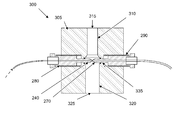
- FIGS. 3A and 3B show a schematic optical flow cell detector 300 in accordance with an embodiment of the invention.
- This optical flow cell detector 300 comprises a detector body 305 with a first bore 310 extending from an external surface of the detector body 300 forming the sample inlet 315 , a second bore 320 , concentric with and wider than the first bore 310 , extending from the first bore to an external surface of the detector body 300 forming the sample outlet 325 . Together, the first and the second bores form a fluid flow channel 330 .
- the input light guide 240 and the output light guide 270 are arranged in opposing sections of the third bore 335 such that they protrude into the second bore 320 .
- the light guides 240 and 270 are arranged in support ferrules 280 and 290 that are extended into the fluid flow channel 330 to support the thin light guides 240 and 270 , whereby the waveguides may be comprised of thin light guiding elements, such as optic fibers or the like.
- the diameter of the input and output light guides 240 and 270 is less than 2 mm, such as 1 mm, 0.8 mm, 0.5 mm or the like.
- the input light guide 240 is comprised of an optic fiber with a core diameter of about 400 ⁇ m and the output light guide 240 is comprised of an optic fiber with a core diameter of about 600 ⁇ m.
- a very small optical cross sectional area 245 with high light flux is achieved.
- FIG. 3 c shows an enlargement of the flow cell channel 230 region of the flow cell detector 200 of FIGS. 3A and 3B , wherein it can be seen that the resulting optical cross sectional area 245 in the present flow cell detector 200 can be made even smaller in this embodiment.
- FIG. 5 shows a schematic optical flow cell dual detector in accordance with an embodiment of the invention.
- FIG. 6 shows a schematic UV absorption graph for an optical flow cell detector in accordance with an embodiment of the invention, in comparison with a schematic graph for a prior art wide gap detector.
- the signal from the wide gap detector is saturated well before the double peak is reached and information regarding the double peak shape and position is not registered.
- the small gap detector according to the present invention the full double peak is registered, but the sensitivity at lower concentrations is may be somewhat reduced.
- FIG. 7 is an experimental graph showing the linearity of a optical flow cell detector in accordance with an embodiment of the invention.
- a prototype optical flow cell detector with 0.12 mm path length was subsequently tested with a dilution series of polyclonal hIgG (starting at 165 mg/ml) showing linearity up to at least 84 mg/ml.
- FIG. 8 is an experimental graph showing the linearity of a optical flow cell detector in accordance with an embodiment of the invention in comparison with a prior art wide gap detector.
- the prototype cell was reconfigured to 0.07 mm path length and tested with a dilution series of BSA up to 150 mg/ml and compared to a 2 mm cell. Linearity up to 150 mg/ml (and probably more than that) was demonstrated for the 0.07 mm cell while the 2 mm cell was linear only up to about 10 mg/ml.
Landscapes
- Physics & Mathematics (AREA)
- Health & Medical Sciences (AREA)
- Life Sciences & Earth Sciences (AREA)
- Chemical & Material Sciences (AREA)
- Analytical Chemistry (AREA)
- Biochemistry (AREA)
- General Health & Medical Sciences (AREA)
- General Physics & Mathematics (AREA)
- Immunology (AREA)
- Pathology (AREA)
- Optical Measuring Cells (AREA)
- Investigating Or Analysing Materials By Optical Means (AREA)
Applications Claiming Priority (4)
| Application Number | Priority Date | Filing Date | Title |
|---|---|---|---|
| SE1050090 | 2010-01-28 | ||
| SE1050090-8 | 2010-01-28 | ||
| SE1050090 | 2010-01-28 | ||
| PCT/SE2011/050078 WO2011093775A1 (en) | 2010-01-28 | 2011-01-26 | Optical flow cell detector |
Publications (2)
| Publication Number | Publication Date |
|---|---|
| US20120327397A1 US20120327397A1 (en) | 2012-12-27 |
| US8649005B2 true US8649005B2 (en) | 2014-02-11 |
Family
ID=44319579
Family Applications (1)
| Application Number | Title | Priority Date | Filing Date |
|---|---|---|---|
| US13/522,880 Active US8649005B2 (en) | 2010-01-28 | 2011-01-26 | Optical flow cell detector |
Country Status (5)
| Country | Link |
|---|---|
| US (1) | US8649005B2 (enExample) |
| EP (1) | EP2529198B1 (enExample) |
| JP (1) | JP5890783B2 (enExample) |
| CN (1) | CN102713564B (enExample) |
| WO (1) | WO2011093775A1 (enExample) |
Cited By (6)
| Publication number | Priority date | Publication date | Assignee | Title |
|---|---|---|---|---|
| US9146189B2 (en) | 2014-02-28 | 2015-09-29 | Asl Analytical, Inc. | Optical cell with disposable fluid cartridge |
| US20180088026A1 (en) * | 2015-04-10 | 2018-03-29 | Ge Healthcare Bio-Sciences Ab | Device for Holding a Light Guide, Method for Manufacturing Such a Device and an Optical Flow Cell Incorporating Such a Device |
| WO2018153743A2 (en) | 2017-02-21 | 2018-08-30 | Ge Healthcare Bio-Sciences Ab | Method for adapting uv cell pathlength in a chromatography system |
| US10197494B2 (en) | 2016-06-23 | 2019-02-05 | Biocomp Instruments Inc. | Flow cell and system for simultaneous measurement of absorbance and emission in a sample |
| US10345227B2 (en) | 2014-07-23 | 2019-07-09 | Infineon Technologies Ag | Sensing systems and methods using a coupling structure |
| US11543344B2 (en) | 2016-02-26 | 2023-01-03 | Cytiva Sweden Ab | Apparatus and method for measuring the light absorbance of a substance in a solution |
Families Citing this family (16)
| Publication number | Priority date | Publication date | Assignee | Title |
|---|---|---|---|---|
| GB2512527B (en) * | 2011-12-02 | 2017-03-01 | Biochrom Ltd | Device for receiving small volume liquid samples |
| GB201120769D0 (en) * | 2011-12-02 | 2012-01-11 | Biochrom Ltd | Improvements in and relating to devices for recieving liquid samples |
| WO2016079797A1 (ja) * | 2014-11-18 | 2016-05-26 | 日本メクトロン株式会社 | インライン式濃度測定プローブ及び濃度測定システム |
| US10185088B2 (en) * | 2014-12-18 | 2019-01-22 | Ge Healthcare Bio-Sciences Ab | Optical fiber arrangement for a system for measuring the light absorption or determining the concentration of a substance |
| GB201506095D0 (en) | 2015-04-10 | 2015-05-27 | Ge Healthcare Bio Sciences Ab | Optical flow cell for an optical measuring device |
| KR101684407B1 (ko) * | 2015-05-22 | 2016-12-08 | 전남대학교산학협력단 | 광학 센서를 이용한 수질 오염 측정 시스템 및 수질 오염 측정 장치 |
| EP3325944B1 (en) * | 2015-07-24 | 2019-12-11 | Hewlett-Packard Development Company, L.P. | Light guide for fluid testing cells |
| CN105424603B (zh) * | 2015-12-14 | 2019-05-21 | 重庆川仪分析仪器有限公司 | 基于分光光度法的检测池总成 |
| GB201612010D0 (en) * | 2016-07-11 | 2016-08-24 | Ge Healthcare | A method and a measuring device for measuring the absorbance of a substance in a solution |
| GB201620266D0 (en) * | 2016-11-30 | 2017-01-11 | Ge Healthcare Bio Sciences Ab | Optical flow cell |
| US10711237B2 (en) * | 2017-08-22 | 2020-07-14 | Idex Health & Science Llc | Apparatus and methods for bioprocesses and other processes |
| US10960393B2 (en) | 2017-08-22 | 2021-03-30 | Idex Health And Science Llc | Apparatus and methods for bioprocesses and other processes |
| JP7113604B2 (ja) * | 2017-09-22 | 2022-08-05 | 株式会社Screenホールディングス | 吸光度測定装置および吸光度測定方法 |
| GB201808748D0 (en) | 2018-05-29 | 2018-07-11 | Ge Healthcare Bio Sciences Ab | Optical flow cell |
| JP7360100B2 (ja) * | 2018-09-25 | 2023-10-12 | 株式会社フジキン | 濃度測定装置 |
| WO2021026284A1 (en) * | 2019-08-06 | 2021-02-11 | Amgen Inc. | Systems and methods for determining protein concentrations of unknown protein samples based on automated multi-wavelength calibration |
Citations (5)
| Publication number | Priority date | Publication date | Assignee | Title |
|---|---|---|---|---|
| US5140169A (en) * | 1991-04-25 | 1992-08-18 | Conoco Inc. | Long path flow cell resistant to corrosive environments for fiber optic spectroscopy |
| US5423513A (en) * | 1992-11-13 | 1995-06-13 | Lc Packings International | Method of and a capillary flow cell for analysing fluid samples |
| US6266139B1 (en) | 1996-04-23 | 2001-07-24 | Joachim Mannhardt | Capillary tube holder |
| US6600558B2 (en) * | 2000-08-22 | 2003-07-29 | Nippon Telegraph And Telephone Corporation | Micro-fluidic cell for optical detection of gases and method for producing same |
| WO2008132611A2 (en) | 2007-04-13 | 2008-11-06 | C Technologies, Inc. | Interactive variable pathleingth device |
Family Cites Families (13)
| Publication number | Priority date | Publication date | Assignee | Title |
|---|---|---|---|---|
| JPS6134461U (ja) * | 1984-07-31 | 1986-03-03 | 修一 村田 | 体外循環回路内レ−ザ−気泡検出装置用セル |
| JPS61182841U (enExample) * | 1985-05-07 | 1986-11-14 | ||
| ATE60133T1 (de) * | 1987-07-22 | 1991-02-15 | Ciba Geigy Ag | Prozesskuevette. |
| EP0326511B1 (de) * | 1988-01-14 | 1992-02-26 | Ciba-Geigy Ag | Mikrodurchflusszelle |
| JPH0593688A (ja) * | 1991-09-30 | 1993-04-16 | Shimadzu Corp | 分光分析装置 |
| US5442437A (en) * | 1993-09-13 | 1995-08-15 | Atlantic Richfield Company | Sample cell and probe for spectrophotometer |
| IL116972A0 (en) * | 1996-01-31 | 1996-05-14 | Israel Atomic Energy Comm | Optical flow cell for use in spectral analysis |
| US6188813B1 (en) * | 1999-02-10 | 2001-02-13 | Waters Investments Limited | Flow cell, analyte measurement apparatus and methods related thereto |
| WO2001081899A2 (en) | 2000-04-26 | 2001-11-01 | Glaxo Group Limited | Method and apparatus for in-situ spectroscopic analysis |
| US6542231B1 (en) * | 2000-08-22 | 2003-04-01 | Thermo Finnegan Llc | Fiber-coupled liquid sample analyzer with liquid flow cell |
| JP2002181694A (ja) * | 2000-12-13 | 2002-06-26 | Sekisui Chem Co Ltd | 分光光度計 |
| JP2007113979A (ja) * | 2005-10-19 | 2007-05-10 | Ebara Corp | マルチ分光分析装置 |
| JP4712745B2 (ja) * | 2007-03-06 | 2011-06-29 | 倉敷紡績株式会社 | 透過光測定用フローセル |
-
2011
- 2011-01-26 CN CN201180007580.1A patent/CN102713564B/zh active Active
- 2011-01-26 US US13/522,880 patent/US8649005B2/en active Active
- 2011-01-26 EP EP11737364.7A patent/EP2529198B1/en active Active
- 2011-01-26 JP JP2012551126A patent/JP5890783B2/ja active Active
- 2011-01-26 WO PCT/SE2011/050078 patent/WO2011093775A1/en not_active Ceased
Patent Citations (5)
| Publication number | Priority date | Publication date | Assignee | Title |
|---|---|---|---|---|
| US5140169A (en) * | 1991-04-25 | 1992-08-18 | Conoco Inc. | Long path flow cell resistant to corrosive environments for fiber optic spectroscopy |
| US5423513A (en) * | 1992-11-13 | 1995-06-13 | Lc Packings International | Method of and a capillary flow cell for analysing fluid samples |
| US6266139B1 (en) | 1996-04-23 | 2001-07-24 | Joachim Mannhardt | Capillary tube holder |
| US6600558B2 (en) * | 2000-08-22 | 2003-07-29 | Nippon Telegraph And Telephone Corporation | Micro-fluidic cell for optical detection of gases and method for producing same |
| WO2008132611A2 (en) | 2007-04-13 | 2008-11-06 | C Technologies, Inc. | Interactive variable pathleingth device |
Non-Patent Citations (2)
| Title |
|---|
| Flowers, P., et al., Analytical Chemistry, 68, (1996), 199-202. |
| Lacki, P., et al., Eurosensors. Proceedings of the European Conference on Solid-State Transducers and the UK Conference on Sensors and Their Applications, 1, (1998), 343-346. |
Cited By (8)
| Publication number | Priority date | Publication date | Assignee | Title |
|---|---|---|---|---|
| US9146189B2 (en) | 2014-02-28 | 2015-09-29 | Asl Analytical, Inc. | Optical cell with disposable fluid cartridge |
| US10345227B2 (en) | 2014-07-23 | 2019-07-09 | Infineon Technologies Ag | Sensing systems and methods using a coupling structure |
| US20180088026A1 (en) * | 2015-04-10 | 2018-03-29 | Ge Healthcare Bio-Sciences Ab | Device for Holding a Light Guide, Method for Manufacturing Such a Device and an Optical Flow Cell Incorporating Such a Device |
| US10261008B2 (en) * | 2015-04-10 | 2019-04-16 | Ge Healthcare Bio-Sciences Ab | Device for holding a light guide, method for manufacturing such a device and an optical flow cell incorporating such a device |
| US11543344B2 (en) | 2016-02-26 | 2023-01-03 | Cytiva Sweden Ab | Apparatus and method for measuring the light absorbance of a substance in a solution |
| US12352685B2 (en) | 2016-02-26 | 2025-07-08 | Cytiva Sweden Ab | Apparatus and method for measuring the light absorbance of a substance in a solution |
| US10197494B2 (en) | 2016-06-23 | 2019-02-05 | Biocomp Instruments Inc. | Flow cell and system for simultaneous measurement of absorbance and emission in a sample |
| WO2018153743A2 (en) | 2017-02-21 | 2018-08-30 | Ge Healthcare Bio-Sciences Ab | Method for adapting uv cell pathlength in a chromatography system |
Also Published As
| Publication number | Publication date |
|---|---|
| EP2529198B1 (en) | 2017-12-27 |
| CN102713564B (zh) | 2016-07-20 |
| EP2529198A1 (en) | 2012-12-05 |
| JP5890783B2 (ja) | 2016-03-22 |
| WO2011093775A1 (en) | 2011-08-04 |
| EP2529198A4 (en) | 2014-02-19 |
| CN102713564A (zh) | 2012-10-03 |
| US20120327397A1 (en) | 2012-12-27 |
| JP2013518278A (ja) | 2013-05-20 |
Similar Documents
| Publication | Publication Date | Title |
|---|---|---|
| US8649005B2 (en) | Optical flow cell detector | |
| US5680209A (en) | Spectroscopic systems for the analysis of small and very small quantities of substances | |
| US10551303B2 (en) | Flow cell optical detection system | |
| JP3657900B2 (ja) | 液体フローセルを伴ったファイバー結合液体サンプル分析器 | |
| US5917606A (en) | Photometric flow apparatus for small sample volumes and method of making same | |
| US9146192B2 (en) | Integrated light scattering and ultraviolet absorption measurement system | |
| US4475813A (en) | Divergent light optical systems for liquid chromatography | |
| JP2020508451A (ja) | 液体クロマトグラフィー用の統合型照明検出フローセル | |
| US4006990A (en) | Convergent light illuminated flow cell for liquid chromatography | |
| US20120069340A1 (en) | Flow cell exploiting radiation within cell wall | |
| US3975104A (en) | Convergent light illuminated flow cell for liquid chromatography | |
| KR20140103304A (ko) | 소 체적 액체 샘플을 수용하기 위한 장치 | |
| WO2014021099A1 (ja) | 液体クロマトグラフ分析装置 | |
| US7724356B2 (en) | Apparatus for measuring differential refractive index | |
| EP3420337A1 (en) | A method and a measuring device for measuring the absorbance of a substance in at least one solution | |
| JPH02276927A (ja) | 一体型分光器とオンライン用分光計測装置 | |
| CN104614071A (zh) | 一种分光光度计的小型化光路结构及其应用方法 | |
| JP7147952B2 (ja) | クロマトグラフ用検出器 | |
| US7420665B2 (en) | Optical detection device with reduced light throughput oscillations | |
| EP0168939A2 (en) | Liquid chromatographic eluent absorbance detector | |
| Imai et al. | Multi-channel Deep-UV absorbance measurement setup for multi-capillary electrophoresis with two fiber arrays facing each other | |
| CA1060227A (en) | Convergent light illuminated flow cell for liquid chromatography | |
| Driver et al. | Sample interface in on-line process sensing: liquid phase and gas phase sampling of optically homogenous processes | |
| JPS63158457A (ja) | 液体クロマトグラフイ用濃度測定ブロツク |
Legal Events
| Date | Code | Title | Description |
|---|---|---|---|
| AS | Assignment |
Owner name: GE HEALTHCARE BIO-SCIENCES AB, SWEDEN Free format text: ASSIGNMENT OF ASSIGNORS INTEREST;ASSIGNOR:TORMOD, STIG;REEL/FRAME:028579/0504 Effective date: 20110502 |
|
| STCF | Information on status: patent grant |
Free format text: PATENTED CASE |
|
| FPAY | Fee payment |
Year of fee payment: 4 |
|
| AS | Assignment |
Owner name: CYTIVA SWEDEN AB, SWEDEN Free format text: CHANGE OF NAME;ASSIGNOR:GE HEALTHCARE BIO-SCIENCES AB;REEL/FRAME:054262/0184 Effective date: 20200612 |
|
| MAFP | Maintenance fee payment |
Free format text: PAYMENT OF MAINTENANCE FEE, 8TH YEAR, LARGE ENTITY (ORIGINAL EVENT CODE: M1552); ENTITY STATUS OF PATENT OWNER: LARGE ENTITY Year of fee payment: 8 |
|
| MAFP | Maintenance fee payment |
Free format text: PAYMENT OF MAINTENANCE FEE, 12TH YEAR, LARGE ENTITY (ORIGINAL EVENT CODE: M1553); ENTITY STATUS OF PATENT OWNER: LARGE ENTITY Year of fee payment: 12 |