US8620042B2 - Image processing apparatus, image processing method, and computer-readable recording medium - Google Patents
Image processing apparatus, image processing method, and computer-readable recording medium Download PDFInfo
- Publication number
- US8620042B2 US8620042B2 US13/215,599 US201113215599A US8620042B2 US 8620042 B2 US8620042 B2 US 8620042B2 US 201113215599 A US201113215599 A US 201113215599A US 8620042 B2 US8620042 B2 US 8620042B2
- Authority
- US
- United States
- Prior art keywords
- closed region
- energy
- initial
- image
- image processing
- Prior art date
- Legal status (The legal status is an assumption and is not a legal conclusion. Google has not performed a legal analysis and makes no representation as to the accuracy of the status listed.)
- Active, expires
Links
Images
Classifications
-
- G—PHYSICS
- G06—COMPUTING; CALCULATING OR COUNTING
- G06T—IMAGE DATA PROCESSING OR GENERATION, IN GENERAL
- G06T7/00—Image analysis
- G06T7/0002—Inspection of images, e.g. flaw detection
- G06T7/0012—Biomedical image inspection
-
- G—PHYSICS
- G06—COMPUTING; CALCULATING OR COUNTING
- G06T—IMAGE DATA PROCESSING OR GENERATION, IN GENERAL
- G06T7/00—Image analysis
- G06T7/10—Segmentation; Edge detection
- G06T7/149—Segmentation; Edge detection involving deformable models, e.g. active contour models
Definitions
- the present invention relates to an image processing apparatus, an image processing method, and a computer-readable recording medium for processing an intraluminal image that is a captured image of an intralumen.
- endoscopes are widely used as a medical observation device of a type that is introduced inside a body of an examinee such as a patient and observes the inside of a lumen of the body.
- an eating-type endoscope capsule endoscope
- an imaging device, a communication device transmitting image data imaged by the imaging device outside the body in a wireless manner, and the like are provided in a capsule-type casing. Since observation and diagnosis using an image of the inside of a lumen (intraluminal image) that is imaged with the medical observation device requires abundant experience, a medical diagnosis supporting function that supports the diagnosis of a doctor is desired.
- a technology is proposed which automatically detects an abnormal portion such as a lesion from an intraluminal image and presents the abnormal portion to a medical doctor or others.
- Japanese Laid-open Patent Publication No. 2002-99896 a technology is disclosed in which candidates for a microcalcification shading that is one feature of a cancerous portion of breast cancer are stably detected by using a shape-dependent filter regardless of a coarse structure or a linear structure.
- a second shape-dependent filter is prepared in advance, of which filter characteristics are optimized in accordance with various conditions such as photographing conditions, reading conditions, image contrast, and the size of a microcalcification shading, combined conditions thereof, or the like based on the supposed shape of the microcalcification shading.
- a microstructure image representing a microstructure potion is generated by eliminating a linear structure formed inside the image by using a first shape-dependent filter that is a morphology filter (for example, Kohata et al., “Extraction of Microcalcification Image Through Morphology Filter Using Multiple Structure Element”, The Institute of Electronic, Information, and Communication Engineers Journal, D-II, Vol. J75-D-II, No. 7, P 1170 to 1176, July 1992 or Kohata et al., “Basics of Morphology and Application to Mammogram Processing”, Medical Imaging Technology, Vol. 12, No. 1, January 1994).
- a first shape-dependent filter that is a morphology filter
- the enhanced image is generated in which only the candidates for the microcalcification shading are enhanced more than the periphery thereof (a portion other than candidates for the microcalcification shading, including a coarse structure portion, a linear structure portion, and the like that could not be eliminated by the first shape-dependent filter).
- An image processing apparatus includes a gradient strength calculating unit that calculates gradient strength of a pixel value of each pixel of an intraluminal image that is a captured image of an intralumen; a closed region extracting unit that extracts a closed region from the intraluminal image, the closed region satisfying conditions that the pixel of which gradient strength is a predetermined value or more is not included in the closed region and a boundary of the closed region does not bend with predetermined curvature or higher toward an inner side of the closed region; and an abnormal portion detecting unit that detects an abnormal portion located inside the closed region.
- the closed region extracting unit includes an initial closed region setting unit that sets an initial closed region having an initial shape of the closed region based on the gradient strength; an energy calculating unit that calculates values of a plurality of types of energy that at least include energy determined based on an outer shape of the closed region and energy determined based on the gradient strength on the boundary of the closed region; and an energy weighted-sum calculating unit that calculates a weighted sum of the plurality of types of energy.
- the closed region is extracted by transforming the initial closed region based on the weighted sum.
- the initial closed region setting unit includes a range determining unit that determines a set range of the initial closed region based on the gradient strength.
- An image processing apparatus includes a gradient strength calculating unit that calculates gradient strength of a pixel value of each pixel of an intraluminal image that is a captured image of an intralumen; a closed region extracting unit that extracts a closed region from the intraluminal image, the closed region satisfying conditions that the pixel of which gradient strength is a predetermined value or more is not included in the closed region and a boundary of the closed region does not bend with predetermined curvature or higher toward an inner side of the closed region; and an abnormal portion detecting unit that detects an abnormal portion located inside the closed region.
- the closed region extracting unit includes an initial closed region setting unit that sets an initial closed region having an initial shape of the closed region based on the gradient strength; an energy calculating unit that calculates values of a plurality of types of energy that at least include energy determined based on an outer shape of the closed region and energy determined based on the gradient strength on the boundary of the closed region; an energy weighting factor setting unit that sets a weighting factor for at least one type of energy among the plurality of types of energy based on a position of the initial closed region; and an energy weighted-sum calculating unit that calculates a weighted sum of the plurality of types of energy.
- the closed region is extracted by transforming the initial closed region based on the weighted sum.
- An image processing method includes calculating gradient strength of a pixel value of each pixel of an intraluminal image that a captured image of an intralumen; extracting a closed region from the intraluminal image, the closed region satisfying conditions that the pixel of which gradient strength is a predetermined value or more is not included in the closed region and a boundary of the closed region does not bend with predetermined curvature or higher toward an inner side of the closed region; and detecting an abnormal portion located inside the closed region.
- the extracting includes setting an initial closed region that is an initial shape of the closed region based on the gradient strength; calculating values of a plurality of types of energy that at least include energy determined based on an outer shape of the closed region and energy determined based on the gradient strength on the boundary of the closed region; and calculating a weighted sum of the plurality of types of energy.
- the closed region is extracted by transforming the initial closed region based on the weighted sum.
- the setting includes determining a set range of the initial closed region based on the gradient strength.
- An image processing method includes calculating gradient strength of a pixel value of each pixel of an intraluminal image that is a captured image of an intralumen; extracting a closed region from the intraluminal image, the closed region satisfying conditions that the pixel of which gradient strength is a predetermined value or more is not included in the closed region and a boundary of the closed region does not bend with predetermined curvature or higher toward an inner side of the closed region; and detecting an abnormal portion located inside the closed region.
- the extracting includes setting an initial closed region having an initial shape of the closed region based on the gradient strength; calculating values of a plurality of types of energy that at least include energy determined based on an outer shape of the closed region and energy determined based on the gradient strength on the boundary of the closed region; setting a weighting factor for at least one type of energy among the plurality of types of energy based on a position of the initial closed region; and calculating a weighted sum of the plurality of types of energy.
- the closed region is extracted by transforming the initial closed region based on the weighted sum.
- a non-transitory computer-readable storage medium has an executable program stored thereon.
- the program instructs a processor to perform: calculating gradient strength of a pixel value of each pixel of an intraluminal image that is a captured image of an intralumen; extracting a closed region from the intraluminal image, the closed region satisfying conditions that the pixel of which gradient strength is a predetermined value or more is not included in the closed region and a boundary of the closed region does not bend with predetermined curvature or higher toward an inner side of the closed region; and detecting an abnormal portion located inside the closed region.
- the extracting includes setting an initial closed region having an initial shape of the closed region based on the gradient strength; calculating values of a plurality of types of energy that at least include energy determined based on an outer shape of the closed region and energy determined based on the gradient strength on the boundary of the closed region; and calculating a weighted sum of the plurality of types of energy.
- the closed region is extracted by transforming the initial closed region based on the weighted sum.
- the setting includes determining a set range of the initial closed region based on the gradient strength.
- a non-transitory computer-readable storage medium has an executable program stored thereon.
- the program instructs a processor to perform: calculating gradient strength of a pixel value of each pixel of an intraluminal image that is a captured image of an intralumen; extracting a closed region from the intraluminal image, the closed region satisfying conditions that the pixel of which gradient strength is a predetermined value or more is not included in the closed region and a boundary of the closed region does not bend with predetermined curvature or higher toward an inner side of the closed region; and detecting an abnormal portion located inside the closed region.
- the extracting includes setting an initial closed region having an initial shape of the closed region based on the gradient strength; calculating values of a plurality of types of energy that at least include energy determined based on an outer shape of the closed region and energy determined based on the gradient strength on the boundary of the closed region; setting a weighting factor for at least one type of energy among the plurality of types of energy based on a position of the initial closed region; and calculating a weighted sum of the plurality of types of energy.
- the closed region is extracted by transforming the initial closed region based on the weighted sum.
- FIG. 1 is a block diagram illustrating the functional configuration of an image processing apparatus according to a first embodiment
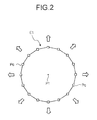
- FIG. 2 is a diagram illustrating the principle of extracting a closed region
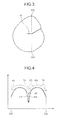
- FIG. 3 is a diagram illustrating a closed region that includes an edge such as a groove position on the inside thereof;
- FIG. 4 is a diagram illustrating a change curve of pixel values on a line denoted by a dashed-dotted line in FIG. 3 ;
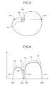
- FIG. 5 is a diagram illustrating a closed region that includes an edge largely bending such as a contour portion on the boundary;
- FIG. 6 is a diagram illustrating a change curve of pixel values on a line denoted by a dashed-dotted line in FIG. 5 ;
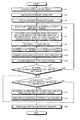
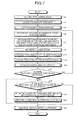
- FIG. 7 is the entire flowchart illustrating the processing sequence performed by the image processing apparatus according to the first embodiment
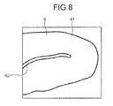
- FIG. 8 is a schematic diagram illustrating an example of an intraluminal image
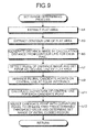
- FIG. 9 is a flowchart illustrating the detailed processing sequence of a set range determining process according to the first embodiment
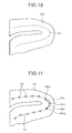
- FIG. 10 is a schematic diagram illustrating a flat area that is extracted from the intraluminal image illustrated in FIG. 8 ;
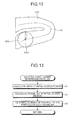
- FIG. 11 is a diagram illustrating candidate points arranged on a central line of the flat area illustrated in FIG. 10 ;
- FIG. 12 is a diagram illustrating an example of an initial closed region set in a set range within the flat area
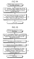
- FIG. 13 is a flowchart illustrating the detailed processing sequence of a control point number determining process
- FIG. 14 is a flowchart illustrating the detailed processing sequence of an energy weighing factor setting process according to the first embodiment
- FIG. 15 is a flowchart illustrating the detailed processing sequence of a closed region extracting process
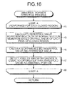
- FIG. 16 is a flowchart illustrating the detailed processing sequence of an abnormal portion detecting process
- FIG. 17 is a block diagram illustrating the functional configuration of an image processing apparatus according to a second embodiment
- FIG. 18 is the entire flowchart illustrating the processing sequence performed by the image processing apparatus according to the second embodiment.
- FIG. 19 is a flowchart illustrating the detailed processing sequence of a set range determining process according to the second embodiment
- FIG. 20 is a schematic diagram illustrating an example of an intraluminal image
- FIG. 21 is a flowchart illustrating the detailed processing sequence of an energy weighing factor setting process according to the second embodiment
- FIG. 22 is a block diagram illustrating the functional configuration of an image processing apparatus according to a third embodiment
- FIG. 23 is the entire flowchart illustrating the processing sequence performed by the image processing apparatus according to the third embodiment.
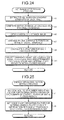
- FIG. 24 is a flowchart illustrating the detailed processing sequence of a set range determining process according to the third embodiment
- FIG. 25 is a flowchart illustrating the detailed processing sequence of an energy weighing factor setting process according to the third embodiment
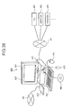
- FIG. 26 is a system configuration diagram illustrating the configuration of a computer system to which the present invention is applied.
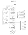
- FIG. 27 is a block diagram illustrating the configuration of a main body unit of the computer system illustrated in FIG. 26 .
- An image processing apparatus performs a process of detecting an abnormal portion such as a lesion or a bleeding site from an intraluminal image by processing an image (intraluminal image) that is acquired by imaging a lumen inside a body such as a gastrointestinal tract of the inside of a body of an examinee by using a medical observation device such as an endoscope or a capsule endoscope.
- an image intraluminal image
- a medical observation device such as an endoscope or a capsule endoscope.
- the intraluminal image is a color image, for example, having pixel values for wavelength components red (R), green (G), and blue (B) for each pixel.
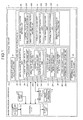
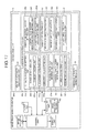
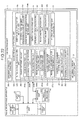
- FIG. 1 is a block diagram illustrating the functional configuration of an image processing apparatus 1 according to the first embodiment.
- the image processing apparatus 1 according to the first embodiment includes an image acquiring unit 11 , an input unit 12 , a display unit 13 , a recording unit 14 , a calculating unit 20 , and a control unit 15 that controls the overall operation of the image processing apparatus 1 .
- the image acquiring unit 11 is used for acquiring image data of an intraluminal image that is imaged by a medical observation device, and the image data of the intraluminal image acquired by the image acquiring unit 11 is recorded in the recording unit 14 , is processed by the calculating unit 20 , and then, is appropriately displayed on the display unit 13 as is necessary.
- the image acquiring unit 11 includes a reader device to which the recording medium is detachably attached and reads out the stored image data of the intraluminal image.
- the image acquiring unit 11 includes a communication device that is used for a connection to the server and the like. Then, the image processing apparatus 1 acquires the image data of the intraluminal image by performing data communication with the server through the image acquiring unit 11 .
- the image acquiring unit 11 may include an interface device or the like that receives an image signal output from the medical observation device such as an endoscope as input through a cable.
- the input unit 12 is realized, for example, by a keyboard, a mouse, a touch panel, or various switches and outputs an input signal to the control unit 15 .
- the display unit 13 is realized by a display device such as an LCD or an EL display and displays various screens including the intraluminal image under the control of the control unit 15 .
- the recording unit 14 is realized by various IC memories such as a ROM provided as a rewritable flash memory or the like and a RAM, a hard disk that is built in or is connected through a data communication terminal, an information recording medium such as a CD-ROM, a reading device thereof, and the like.
- a program used for realizing various functions included in the image processing apparatus 1 data used during execution of the program, and the like are recorded therein in advance or are temporarily recorded at each processing time.
- Image data of the intraluminal image that is acquired by the image acquiring unit 11 is recorded in the recording unit 14 .
- an image processing program 141 that is used for detecting an abnormal portion from the intraluminal image by realizing the process according to the first embodiment is recorded.
- the calculation unit 20 is realized by hardware such as a CPU and performs various calculation processes for detecting an abnormal portion by processing the intraluminal image.
- This calculation unit 20 includes a gradient strength calculating unit 21 , a closed region extracting unit 22 , and an abnormal portion detecting unit 32 .
- the gradient strength calculating unit 21 calculates the gradient strength of the pixel value of each pixel based on the pixel value of each pixel of the intraluminal image.
- the closed region extracting unit 22 extracts a closed region satisfying the above-described conditions from the intraluminal image.
- This closed region extracting unit 22 includes an initial closed region setting unit 23 , an energy weighting factor setting unit 29 , an energy calculating unit 30 , and an energy weighted-sum calculating unit 31 .
- the closed region extracting unit 22 extracts a closed region by transforming the initial closed region based on the weighted-sum calculated by the energy weighted-sum calculating unit 31 .
- the initial closed region setting unit 23 sets an initial closed region having an initial shape of a closed region.
- This initial closed region setting unit 23 includes a range determining unit 24 , a closed region size determining unit 27 , and a control point number determining unit 28 .
- the range determining unit 24 is a functional unit that determine a range (set range) inside the intraluminal image in which the initial closed region is set based on the gradient strength of each pixel and includes a flat area extracting unit 241 and an area shape information calculating unit 242 .
- the flat area extracting unit 241 extracts from the intraluminal image an area that is made up of a plurality of pixels which have some small degree of values of the gradient strength close to those of the pixels located on the periphery thereof as a flat area.
- the area shape information calculating unit 242 calculates shape information of the flat area.
- This area shape information calculating unit 242 includes a central line calculating unit 243 that calculates a central line of the flat area and a curvature calculating unit 244 that calculates the curvature of the central line.
- the closed region size determining unit 27 determines the size of the initial closed region based on the set range of the initial closed region determined by the range determining unit 24 .
- an inscription area size determining unit 271 of the closed region size determining unit 27 has a predetermined shape (for example, a circular shape) and sets the size of an area that is inscribed in the set range of the initial closed region as the size of the initial closed region.
- the shape of the initial closed region is not limited to the circular shape and may be an appropriate shape.
- the control point number determining unit 28 determines the number of control points, which will be described later, of the initial closed region based on the size of the initial closed region.
- a control point refers to a coordinate point that is located on the boundary of the closed region.
- This control point number determining unit 28 includes an area calculating unit 281 that calculates the area of the initial closed region and a perimeter calculating unit 282 that calculates the perimeter of the initial closed region.
- the energy weighting factor setting unit 29 sets a weighting factor for at least one energy value out of a plurality of energy values calculated by the energy calculating unit 30 based on the position of the initial closed region.
- weighting factors for internal energy to be described later two types of weighting factor (a control point number weighting factor and an area shape weighting factor) are set.
- This energy weighting factor setting unit 29 includes a control point number weighting factor setting unit 291 and an area shape weighting factor setting unit 292 .
- the control point number weighting factor setting unit 291 sets a control point number weighting factor based on the number of control points that is determined by the control point number determining unit 28 .
- a set range is determined within the flat area extracted by the flat area extracting unit 241 , and the initial closed region is set in the set range, which will be described later in detail.
- the area shape weighting factor setting unit 292 sets an area shape weighting factor based on the shape information of the flat area at the set position of the initial closed region.
- the energy calculating unit 30 calculates a plurality of energy values that include at least an energy determined based on the outer shape of the closed region and an energy value determined based on the gradient strength on the boundary of the closed region.
- the energy calculating unit 30 includes an internal energy calculating unit 301 , an image energy calculating unit 302 , and an external energy calculating unit 303 , and calculates three energy values of internal energy and external energy corresponding to the energy determined based on the outer shape of the closed region and image energy corresponding to the energy determined based on the gradient strength on the boundary of the closed region.
- the internal energy represents the degree of smoothness of the boundary of the closed region and is energy that represents a smaller value as the degree of smoothness of the shape of the closed region is higher.
- the image energy is energy that represents a smaller value as the value of the gradient strength on the boundary of the closed region is larger.
- the external energy is energy that represents a smaller value as the size of the closed region is larger.
- the energy weighted-sum calculating unit 31 calculates a weighted sum of the plurality of energies calculated by the energy calculating unit 30 .
- the energy weighted-sum calculating unit 31 calculates a weighted sum of the internal energy, the image energy, and the external energy based on weighting of the internal energy by using the control point number weighting factor and the area shape weighting factor set by the energy weighting factor setting unit 29 .
- the abnormal portion detecting unit 32 detects an abnormal portion located on the inner side (inside) of the boundary of each closed region.
- the control unit 15 is realized by hardware such as a CPU. This control unit 15 controls the overall operation of the image processing apparatus 1 by transmitting instructions, data, or the like to each unit configuring the image processing apparatus 1 based on image data acquired by the image acquiring unit 11 , an input signal input from the input unit 12 , a program or data recorded in the recording unit 14 , and the like.
- FIG. 2 is a diagram illustrating the principle of extracting a closed region and schematically illustrates an initial closed region E 1 that is set by the initial closed region setting unit 23 of the closed region extracting unit 22 .
- the initial closed region E 1 is set by arranging a plurality of control points Pc on pixels located on the boundary and joining the control points Pc. The number of the control points Pc to be arranged is determined based on the size of the initial closed region.
- the internal energy, the image energy, and the external energy described above are calculated for each control point Pc based on the position of each control point Pc, the gradient strength at the position, a distance from the center of gravity (center) P 1 to each control point Pc, and the like, and the control points Pc are moved so as to minimize a weighted sum of the three energies. Accordingly, the initial closed region E 1 is transformed in the direction extending the area, whereby a closed region is extracted.
- an abnormal portion located on the inside of the closed region is detected.
- an abnormal portion is detected by performing a morphology process, for example, a three-dimensional morphology process (shading morphology) using a structure element having a spherical shape.
- a morphology process there are an opening process (reference: “Digital Image Processing”, CG-ARTS Society, P 179 to P 180 , Expansion and Contraction Process ) and a closing process (reference: “Digital Image Processing”, CG-ARTS Society, P 179 to P 180 , Expansion and Contraction Process ).
- the opening process is a process of calculating a locus (surface) through which a maximum value of the outer periphery of a structure element passes when a reference diagram (having a spherical shape in this example) called the structure element is moved while being circumscribed about a target area from a side (lower side) of the target area on which the pixel value is relatively small in a three-dimensional space in which the pixel value is regarded as elevation.
- the closing process is a process of calculating a locus through which a minimum value of the outer periphery of a structure element passes when the structure element is moved while being circumscribed about the target area from a side (upper side) on which the pixel value is relative large in a similar three-dimensional space.
- a value on the acquired locus is used as a reference value, and a pixel having a large difference from the actual pixel value is detected as an abnormal portion.
- a pixel having a large difference between a reference value on the acquired locus and the actual pixel value is detected as an abnormal portion.
- FIG. 3 is a schematic diagram illustrating an example of the closed region and illustrates the closed region that is generated so as to include an edge 51 such as a groove position on the inside thereof.
- FIG. 4 illustrates a change curve L 31 of pixel values with the horizontal axis representing a pixel position between boundary pixels P 31 and P 32 on a line (a line straddling the edge 51 ) denoted by a dashed-dotted line in FIG. 3 and the vertical axis representing the pixel value of each pixel.
- the change in the pixel value at the edge position locally represents a largely-depressed portion. Accordingly, a morphology process (the closing process) is performed for the closed region including the edge 51 therein.
- a locus L 32 (actually, a surface) as denoted by a dashed-dotted line illustrated in FIG. 4 can be acquired.
- the acquired reference value largely deviates from the actual pixel value depending on the shape of the structure element F 3 .
- a value on the acquired locus L 32 is used as a reference value, the pixel value of each pixel is compared with the reference value, and a pixel having a large difference is detected as the abnormal portion. Accordingly, in a case where a closed region including an edge such as a groove position inside the closed region is generated, the portion of the edge 51 may be incorrectly detected as an abnormal portion due to a difference denoted by arrow A 32 .
- FIG. 5 is a schematic diagram illustrating another example of a closed region and illustrates the closed region generated so as to include an edge 52 , which bends toward the inner side with predetermined curvature or more, such as a contour portion on the boundary thereof.
- FIG. 6 illustrates a change curve L 41 of pixel values with the horizontal axis representing a pixel position between boundary pixels P 41 and P 44 located on a line (a line straddling a bending portion of the edge 52 ) denoted by a dashed-dotted line in FIG.
- a structure element F 4 when a structure element F 4 is moved while being circumscribed about the closed region including the edge 52 , of which the boundary largely bends to the inner side, from the upper side by performing the morphology process (closing process) for the closed region (arrow A 41 ), in a case where the structure element F 4 is larger than a gap of the portion in which the change in the pixel value stops, the structure element F 4 does not get into this portion, and thereby a locus L 42 (actually, a surface) as denoted by a dashed-dotted line in FIG. 6 is acquired.
- a contour portion may be incorrectly detected as an abnormal portion due to a difference denoted by arrow A 42 .
- the closed region extracting unit 22 extracts a closed region that satisfies the conditions that a pixel (a pixel located in the edge portion) having gradient strength that is a predetermined value or more is not included on the inside of the region, and the boundary of the region does not bend toward the inner side with predetermined curvature or more. Accordingly, in the detection of an abnormal portion that is performed by applying the morphology process on the latter stage, a reference value can be appropriately acquired.
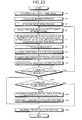
- FIG. 7 is the entire flowchart illustrating the processing sequence performed by the image processing apparatus 1 according to the first embodiment.
- the process described here is realized by executing the image processing program 141 recorded in the recording unit 14 by using the calculating unit 20 .
- the calculation unit 20 acquires an intraluminal image as a processing target (Step a 1 ). Through this process performed here, the calculation unit 20 acquires the intraluminal image as a processing target that is acquired by the image acquiring unit 11 and is recorded in the recording unit 14 by reading it out.
- FIG. 8 is a schematic diagram illustrating an example of the intraluminal image. As illustrated in FIG. 8 , on the intraluminal image, basically, a body tissue such as a mucous membrane 6 of an inner wall of a gastrointestinal track is reflected, and an abnormal area (not shown in the figure) such as a bleeding site is reflected in some cases.
- edges 61 and 62 a groove that is generated due to a folding, an undulation, or the like of the mucous membrane 6 , the contour of the mucous membrane 6 , and the like appear as edges 61 and 62 .
- one edge 62 is represented as an edge that largely bends.
- the gradient strength calculating unit 21 calculates the gradient strength of each pixel, for example, based on G values of pixels of the intraluminal image (Step a 3 ).
- This can be realized by applying a known edge extracting process (reference: “Digital Image Processing”, CG-ARTS Society, P 114 to P 121 , Edge Extraction ) using a first-order differential filter such as a Sobel filter or a second-order differential filter such as a Laplacian filter or the like.
- the reason for using the G value is that the wavelength band thereof is near the absorption wavelength band of hemoglobin, and the sensitivity can be easily acquired, thereby representing the structure of the intraluminal image well.
- the gradient strength is calculated based on the G value of each pixel, the luminance value of each pixel may be calculated, and the gradient strength of each pixel is calculated based on the luminance values.
- FIG. 9 is a flowchart illustrating the detailed processing sequence of the set range determining process according to the first embodiment.
- the flat area extracting unit 241 extracts an area of which the value of the gradient strength is small to some degree, for example, the value of the gradient strength is a threshold value set in advance or less from the intraluminal image as a processing target as a flat area based on the gradient strength calculated for each pixel in Step a 3 illustrated in FIG. 7 in Step b 1 .
- This can be realized by applying, for example, a known area integration method (reference: “Digital Image Processing”, CG-ARTS Society, P 196 , Area Dividing Process ) or the like.
- an area of which the value of the gradient strength is the predetermined threshold value or less is extracted as a flat area
- a flat area may be extracted in consideration of a color (pixel value) as well.
- an area made up of a plurality of pixels which have some small degree of values of the gradient strength (the values of the gradient strength are the predetermined threshold value or less) close to those of the pixels located on the periphery thereof may be extracted as a flat area based on the value of the gradient strength calculated for each pixel in Step a 3 illustrated in FIG. 7 and the pixel values of the intraluminal image as a processing target.
- the central line calculating unit 243 first, extracts the contour line of the flat area as a process of calculating the central line of the flat area, which is extracted in Step b 1 (Step b 3 ).
- This for example, may be realized by applying a known contour tracking method (reference: “Digital Image Processing”, CG-ARTS Society, P 178 to P 179 , Contour Tracking ) or the like.
- the central line calculating unit 243 calculates a distance from the contour line extracted in Step b 3 for each pixel and generates a distance image by setting the pixel value of each pixel to the value of the distance calculated for the pixel (Step b 5 ). Then, the central line calculating unit 243 detects a ridge of the distance image and sets the ridge as the central line of the flat area (Step b 7 ). For example, this can be realized by applying a skeleton extracting process.
- FIG. 10 is a schematic diagram illustrating one of flat areas that are extracted from the intraluminal image illustrated in FIG. 8 and represents a flat area E 51 that is a portion interposed between the edges 61 and 62 illustrated in FIG. 8 .
- Step b 7 illustrated in FIG. 9 a central line L 5 is acquired from the flat area E 51 illustrated in FIG. 10 .
- the curvature calculating unit 244 calculates the curvature of the central line, which is calculated in Step b 7 , as the shape information of the flat area.
- the curvature calculating unit 244 arranges a plurality of candidate points on the central line so as to be equally spaced (Step b 9 ).
- the curvature calculating unit 244 calculates an inner product of two adjacent candidate points for each candidate point arranged in Step b 9 and sets the inner product as the curvature of the central line at the corresponding candidate point (Step b 11 ).
- FIG. 11 is a diagram illustrating candidate points P 5 arranged on a central line L 5 of the flat area E 51 illustrated in FIG. 10 .
- Step b 11 illustrated in FIG. 9 , an inner product of vectors V 51 and V 52 that face toward candidate points P 5 - 2 and P 5 - 3 is calculated and sets the inner product as the value of the curvature of the central line L 5 at the candidate point P 5 - 1 .
- the range determining unit 24 performs threshold value processing for the curvature calculated for each candidate point in Step b 11 . Then, the range determining unit 24 selects candidate points at which the curvature is a threshold value set in advance or less and determines the range of the selected candidate points as a set range of the initial closed region inside the flat area (Step b 13 ). At the position of the candidate point at which the value of the curvature acquired in Step b 11 is large, that is, the position at which the central line largely bends, there is a high possibility that there is an end point of an edge or an edge that largely bends on the outer side of the flat area near the candidate point.
- Step b 13 illustrated in FIG. 9 candidate points (candidate points at which the values of the curvature are small) other than a candidate point such as this candidate point P 5 - 1 at which the value of the curvature is large are selected, and the range of the selected candidate points P 5 is set as the set range of the initial closed region.
- the range of the selected candidate points P 5 is set as the set range of the initial closed region.
- Step b 1 the process of Steps b 3 to b 13 is performed for each flat area, and the set range of the initial closed region is determined for each flat area.
- the process is returned to Step a 5 illustrated in FIG. 7 and thereafter proceeds to Step a 6 .
- the inscription area size determining unit 271 selects one candidate point from among candidate points within the set range that is determined in Step b 13 illustrated in FIG. 9 .
- a candidate point having a largest pixel value in the distance image is selected based on the pixel value of each candidate point (pixel) within the set range in the distance image that is generated in Step b 5 illustrated in FIG. 9 .
- a candidate point may be randomly selected from among candidate points within the set range.
- the inscription area size determining unit 271 calculates the radius r of a circular area that is a circular area having the position of the candidate point selected in Step a 6 as its center position and is inscribed in the contour line of the flat area and sets the radius r as the size of the initial closed region (Step a 7 ). Then, the initial closed region setting unit 23 sets a circular area of the radius r that has the position of the candidate point selected in Step a 6 as its center position and is inscribed in the contour line of the flat area calculated for the corresponding center position in Step a 7 as the initial closed region (Step a 9 ).
- FIG. 12 is a diagram illustrating an initial closed region E 52 that is set as the circular area of the radius r for one candidate point P 5 - 4 that is selected from the range of the candidate points determined as the set range from the candidate points P 5 illustrated in FIG. 11 .
- the control point number determining unit 28 determines the number of control points of the initial closed region by performing a control point number determining process (Step a 11 ).
- FIG. 13 is a flowchart illustrating the detailed processing sequence of the control point number determining process.
- the area calculating unit 281 calculates the area of the initial closed region (Step c 1 ).
- the perimeter calculating unit 282 calculates the perimeter of the initial closed region (Step c 3 ).
- the number of control points is set based on the area or the perimeter here, the number of control points may be determined by using both the area and the perimeter. In a case where the number of control points is set based on the area, the process of Step c 3 may not be performed. Similarly, in a case where the number of control points is set based on the perimeter, the process of Step c 1 may not be performed. When the number of control points is determined, the process is returned to Step a 11 illustrated in FIG. 7 and then proceeds to Step a 13 .
- Step a 13 the energy weighting factor setting unit 29 sets a control point number weighting factor and an area shape weighting factor of the initial closed region by performing an energy weighting factor setting process.
- FIG. 14 is a flowchart illustrating the detailed processing sequence of an energy weighing factor setting process according to the first embodiment.
- the control point number weighting factor setting unit 291 sets the control point number weighting factor for the internal energy based on the number of control points of the initial closed region (Step d 1 ).
- the initial closed region is set by joining a plurality of control points. Accordingly, as the number of control points is increased, a smoother curve is formed, and the internal energy representing the smoothness of the boundary of the closed region has a smaller value.
- the control point number weighting factor for the internal energy is set so as to be increased as the number of control points is increased, in accordance with the following Equation (2).
- Control Point Number Weighting Factor Number of Control Points ⁇ Predetermined Coefficient (2)
- the area shape weighting factor setting unit 292 sets an area shape weighting factor for the internal energy based on the shape information (the curvature of the central line that is calculated in Step b 11 illustrated in FIG. 9 for the candidate point as the center position) of the flat area at the center position of the initial closed region (Step d 3 ).
- the shape information the curvature of the central line that is calculated in Step b 11 illustrated in FIG. 9 for the candidate point as the center position
- the flat area at the center position of the initial closed region (Step d 3 ).
- Step d 3 in order not to extract a closed region into which such an end point of an edge gets or a closed region having a boundary including an edge that largely bends, the area shape weighting factor for the internal energy is set so as to have a larger value as the shape information (the curvature of the central line at the candidate point as the center position) of the flat area becomes larger in accordance with the following Equation (3).
- Area Shape Weighting Factor Curvature of Central Line at Candidate Point as Center Position ⁇ Predetermined Coefficient (3)
- FIG. 15 is a flowchart illustrating the detailed processing sequence of the closed region extracting process.
- the internal energy calculating unit 301 calculates internal energy (E internal ) for each control point of the initial closed region (Step e 1 ), which represents a smaller value as the boundary of the closed region is smoother.
- the energy E is calculated based on an inner product of vectors between two control points (x i ⁇ 1 , y i ⁇ 1 ) and (x i+1 , y i+1 ) adjacent to a control point (x i , y i ) of interest in accordance with the following Equation (4).
- the value of the acquired energy E is weighted by the control point number weighting factor and the area shape weighting factor, which are set in the energy weighting factor setting process illustrated in FIG. 14 , so as to be set as the value of the internal energy E internal .
- This internal energy E internal limits the control point of interest so as not to bend toward the inner side of the closed region with predetermined curvature or more with respect to the positions of the adjacent control points.
- the image energy calculating unit 302 calculates image energy (E image ) for each control point of the initial closed region in Step e 3 , which represents a smaller value as the gradient strength of the boundary of the closed region is higher.
- the image energy E image is represented by the following Equation (5) and is calculated as a reciprocal of the gradient strength of a pixel located at the position of the control point of interest.
- ⁇ S (i) is the value of the gradient strength on the coordinates of the control point (i).
- the external energy calculating unit 303 calculates external energy (E external ) for each control point of the initial closed region in Step e 5 , which represents a smaller value as the size of the closed region is larger.
- the external energy E external is energy at the control point of interest toward the direction in which the closed region extends, for example, is represented by the following Equation (6), and is calculated as a reciprocal of a distance between the center of the closed region and the control point of interest.
- ⁇ represented in Equation (5) and ⁇ represented in Equation (6) represent weighting factors of corresponding energy, and the values thereof may be determined based on an experimental rule.
- Each value of ⁇ or ⁇ may be a fixed value or may be changed, for example, in accordance with a user operation input or the like.
- the energy weighted-sum calculating unit 31 extracts a closed region by acquiring a minimum value of the weighted sum of the internal energy, the image energy, and the external energy by using an active contour extraction method (reference: “Digital Image Processing”, CG-ARTS Society, P 196 to P 200 , Area Dividing Process ) (Step e 7 ).
- a weighted sum of the energies is calculated for each control point as described above and is calculated as a sum of weighted values of three energies of the internal energy E internal acquired by weighing using the control point number weighting factor and the area shape weighting factor, the image energy E image calculated for each control point, and the external energy E external calculated for each control point, and the calculation equation is represented in the following Equation (7).
- Step e 7 a closed region is extracted by transforming the initial closed region so as to minimize the weighted sum.
- the process is returned to Step a 15 illustrated in FIG. 7 and thereafter proceeds to Step a 17 .
- the initial closed region setting unit 23 determines whether or not there is a selectable candidate point within the set range. For example, a candidate point of which the position is located outside the closed region that has been already extracted is set as a selectable candidate point from among candidate points within the set range, and it is determined whether or not there is such a selectable candidate point. Accordingly, a candidate point that is included inside a closed region that has been already extracted is not selected.
- the determination here is a determination of whether or not the position of the candidate point is outside the closed region that has been already extracted, and the initial closed region having the position of the candidate point as its center position may overlap a closed region that has been already extracted.
- Step a 17 the process is returned to Step a 6 , and the inscription area size determining unit 271 selects a candidate point, for example, that has a largest pixel value in the distance image from among selectable candidate points. Thereafter, the process of Step a 7 and after that is performed for the selected candidate point.
- the closed region extracting unit 22 determines whether or not there is an area that has not been extracted as the closed region. In a case where there is an area that has not been extracted as a closed region (Yes in Step a 19 ), the closed region extracting unit 22 sets an initial closed region in the area that has not been extracted as the closed region (Step a 21 ).
- the setting of the initial closed region here may set an initial closed region, for example, having a circular shape so as to include only an area that has not been extracted as a closed region.
- the initial closed region is set such that the center position thereof is not included inside the closed region that has been already extracted and the initial closed region does not include a pixel located at the edge position (a pixel having a large gradient strength value). Then, the closed region extracting unit 22 performs the closed region extracting process for the set initial closed region (Step a 23 ). Although this closed region extracting process may be performed in the approximately same sequence as that of the closed region extracting process illustrated in FIG. 15 , the control point number weighting and the area shape weighting for the internal energy are not performed in the process here.
- Step a 25 the abnormal portion detecting unit 32 performs an abnormal portion detecting process.
- a method is used in which an abnormal portion is detected by performing a known opening process for a closed image for which a known closing process has been performed and performing threshold value processing for a difference between an acquired pixel value (reference value) and the original pixel value.
- FIG. 16 is a flowchart illustrating the detailed processing sequence of an abnormal portion detecting process.
- the abnormal portion detecting unit 32 performs the process of loop A for each closed region (Steps f 1 to f 9 ).
- the abnormal portion detecting unit 32 first, calculates a reference value for each pixel of the closed region as a processing target (Step f 3 ).
- the abnormal portion detecting unit 32 calculates a difference between the pixel value of each pixel of the closed region as the processing target and the reference value calculated in Step f 3 (Step f 5 ).
- the abnormal portion detecting unit 32 performs threshold value processing for the difference and detects a pixel for which the difference is a threshold value set in advance or more as an abnormal portion (Step f 7 ).
- the process of loop A has been performed for all the closed regions, the process is returned to Step a 25 illustrated in FIG. 7 , and thereafter the process ends.
- a result of the abnormal portion detecting process (a result of the detection of an abnormal portion in Step f 7 ) illustrated in FIG. 16 is output to the display unit 13 , and, for example, the abnormal portion inside the intraluminal image is represented and displayed so as to be identifiable from the other areas and is presented to a user such as a medical doctor.
- a flat area is extracted from an intraluminal image, and an initial closed region is set in the set range that is determined within the flat area. Accordingly, an initial closed region that does not include any edge on the inside thereof can be set.
- the curvature of the central line is calculated as the shape information of the flat area, and a range on the central line excluding a position at which the curvature of the central line is high and an end portion of an edge or an edge that largely bends may be presented on the outer side with a high possibility is determined as the set range.
- a closed region is extracted by using an active contour extraction method while weighting the internal energy representing the degree of smoothness of the boundary of the closed region by the control point number weighting factor, which is set to be larger as the number of control points is larger, and the area shape weighing factor, of which the value is larger as the curvature at the position on the central line set as the center, position of the initial closed region is higher.
- the closed region is extracted by transforming the initial closed region in a direction extending the area, in a case where an end point of an edge or an edge that largely bends is present outside the initial closed region, the edge may get into the inside of the closed region or the boundary of the closed region is extended along the edge in the process of transforming the initial closed region so as to extract a closed region of which the boundary includes an edge that largely bends.
- the initial closed region can be so as not to be set at a position at which the bending on the central line is large.
- the weighting of the internal energy can be performed in accordance with the curvature of the central line at a position on the central line set as the center position (weighting by the area shape weighing factor).
- a closed region can be extracted such that a groove position reflected on the intraluminal image is not included on the inside thereof, and the boundary thereof does not include the contour portion. Accordingly, by applying the morphology process for each closed region, an abnormal portion located inside the closed region can be detected. Therefore, an abnormal portion can be detected with high accuracy from the intraluminal image without incorrectly detecting a groove position or a contour potion as the abnormal portion.
- the position of a selected candidate point is set as the center position, and a circular area of a radius r that is inscribed in the contour line of the flat area is set as the initial closed region.
- the initial closed region for example, having a circular shape is set so as to include an area that is not extracted as a closed region.
- a radius r of a circular area set as the initial closed region may be calculated based on the pixel value of the selected candidate point in the distance image so as to be set as the size of the initial closed region.
- a radius r of the circular area may be calculated based on the pixel value at the center position of the initial closed region to be set in the distance image. Described in more detail, a radius r is calculated by using the following Equation (8). Alternatively, the radius r may be calculated by using the following Equation (9).
- the position of the origin point is the position of the candidate point or the center position of the initial closed region set in Step a 21 illustrated in FIG. 7 .
- the value of the distance image is a pixel value at the position of the origin point in the distance image.
- Radius r Value of Distance Image at Position of Origin Point ⁇ Predetermined Coefficient (8)
- Radius r Value of Distance Image at Position of Origin Point ⁇ Predetermined Value (9)
- weighting factors for the internal image although two types of weighting factors (the control point number weighing factor and the area shape weighting factor) are set, any one of the weighting factors may be set. In a case where only the area shape weighting factor is set, the number of control points set in the initial closed region may be fixed.
- the range determining unit 24 is configured so as to include the flat area extracting unit 241 and the area shape information calculating unit 242 as illustrated in FIG. 1 .
- the range determining unit 24 can determine the set range based on the shape information of the flat area, and the area shape weighting factor setting unit 292 of the energy weighting factor setting unit 29 can set the area shape weighting factor based on the shape information of the flat area, the configuration is not limited to a configuration including the range determining unit 24 .
- FIG. 17 is a block diagram illustrating the functional configuration of an image processing apparatus 1 a according to the second embodiment.
- the same reference numeral is assigned to the same configuration as that described in the first embodiment.
- the image processing apparatus 1 a according to the second embodiment includes an image acquiring unit 11 , an input unit 12 , a display unit 13 , a recording unit 14 a , a calculating unit 20 a , and a control unit 15 that controls the overall operation of the image processing apparatus 1 a.
- an image processing program 141 a used for detecting an abnormal portion from an intraluminal image by realizing the process according to the second embodiment is recorded.
- the calculation unit 20 a includes a gradient strength calculating unit 21 , a closed region extracting unit 22 a , and an abnormal portion detecting unit 32 .
- the closed region extracting unit 22 a includes an initial closed region setting unit 23 a , an energy weighting factor setting unit 29 a , an energy calculating unit 30 , and an energy weighted-sum calculating unit 31 .
- the initial closed region setting unit 23 a sets an initial closed region.
- This initial closed region setting unit 23 a includes a range determining unit 25 a , a closed region size determining unit 27 a , and a control point number determining unit 28 .
- the configurations of the range determining unit 25 a and the closed region size determining unit 27 a are different from those of the first embodiment.
- the range determining unit 25 a includes an edge extracting unit 251 a , an end point detecting unit 252 a , and a direction calculating unit 253 a .
- the edge extracting unit 251 a extracts pixels of which the gradient strength is a predetermined value or more as an edge based on the gradient strength of each pixel of the intraluminal image.
- the end point detecting unit 252 a detects end points of an edge.
- the direction calculating unit 253 a calculates the direction of an edge that is continuous to the end point (an edge extending from the end point) as an end point direction.
- the closed region size determining unit 27 a similarly to that of the first embodiment, determines the size of the initial closed region based on the set range of the initial closed region that is determined by a range determining unit 26 a .
- the size of the initial closed region to be set within the set range is determined based on a distance from an edge.
- the shape of the initial closed region is a circular shape, the shape is not limited thereto and may be an appropriate shape.
- the energy weighting factor setting unit 29 a sets a weighing factor for at least one energy among a plurality of energies calculated by the energy calculating unit 30 based on the position of the initial closed region.
- This energy weighting factor setting unit 29 a includes a control point number weighting factor setting unit 291 and an end point direction weighting factor setting unit 293 a and sets two types of weighting factor (a control point number weighting factor and an end point direction weighting factor) as weighting factors for the internal energy.
- the end point direction weighting factor setting unit 293 a sets the end point direction weighting factor based on the set position of the initial closed region and the end point direction.
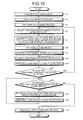
- FIG. 18 is the entire flowchart illustrating the processing sequence performed by the image processing apparatus 1 a according to the second embodiment.
- the process described here is realized by executing the image processing program 141 a recorded in the recording unit 14 a by using the calculating unit 20 a .
- the same reference numeral is assigned to the same process as that of the first embodiment in FIG. 18 .
- FIG. 19 is a flowchart illustrating the detailed processing sequence of the set range determining process according to the second embodiment.
- the edge extracting unit 251 a extracts a pixel of which the value of the gradient strength is, for example, a threshold value set in advance or more from the intraluminal image as the processing target as an edge based on the gradient strength calculated for each pixel in Step a 3 illustrated in FIG. 18 (Step h 1 ).
- This can be realized by using a known edge extracting technique such as Canny or Harris.
- the end point detecting unit 252 a detects an end point of the edge, which is extracted in Step h 1 (Step h 3 ).
- the detection of the end point of the edge can be realized, for example, by applying a known feature point extracting technology (reference: “Digital Image Processing”, CG-ARTS Society, P 188 , Extraction of Feature Point of Fine Line ).
- the direction calculating unit 253 a calculates the direction of an edge that is continuous to the end point as the end point direction based on the detected end point (Step h 5 ). Described in more detail, a direction in which pixels on the edge that is continuous to an end point and are located at positions apart from the pixel as the end point by a predetermined distance are joined is calculated as the end point direction. In a case where a plurality of end points is detected, the end point direction is calculated for each end point.
- the range determining unit 25 a determines an area of pixels at which an angle (hereinafter, also referred to as an “end point direction angle”) formed by a straight line joining the end points and the end point direction calculated in Step h 5 is a predetermined threshold value or less as the set range of the initial closed region (Step h 7 ).
- the calculation of the end point direction angle is performed as follows. First, the pixels of the intraluminal image are sequentially set as a processing target, and an angle formed by a straight line joining the pixel as a processing target and the end point and the end point direction calculated in Step h 5 is calculated as the end point direction angle.
- an end point located closest to the pixel as the processing target is selected, and an angle formed by a straight line joining the pixel as the processing target and the selected end point and the end point direction calculated for the end point in Step h 5 is calculated as the end point direction angle.
- an end point direction angle with respect to an end point from which the distance to the pixel as the processing target is within a predetermined distance set in advance may be calculated.
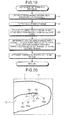
- FIG. 20 is a schematic diagram illustrating an example of an intraluminal image.
- FIG. 20 illustrates edges 71 and 72 that are a groove position of a mucous membrane 7 and a contour portion.
- an end point P 61 of the edge 72 is detected through the process of Step h 3 illustrated in FIG.
- Step h 7 for example, inside the area surrounded by the edge 71 , an area of pixels at which the end point direction angle formed by a straight line joining the end point P 61 and the end point direction is a predetermined threshold value or less is set as the set range of the initial closed region.
- Step h 5 illustrated in FIG. 19 an area acquired by excluding a pixel such as the pixel P 65 at which the end point direction angle is large is set as the set range of the initial closed region.
- an angle ⁇ 1 that is formed by a straight line joining a pixel P 63 and the end point P 61 and the end point direction or an angle ⁇ 2 that is formed by a straight line joining a pixel P 64 and the end point P 61 and the end point direction is small to some degree, and accordingly, such pixels P 63 and P 64 are set within the set range of the initial closed region.
- the range determining unit 25 a arranges candidate points within the set range, which is determined in Step h 7 (Step h 9 ). For example, the range determining unit 25 a delimits the pixels determined as the set range for each connected component and calculates the center of each delimited area. Then, the range determining unit 25 a arranges candidate points at the calculated center positions.
- Step h 1 the process of Steps h 3 to h 9 is performed for each area so as to determine the set range of each initial closed region.
- the process is returned to Step g 5 illustrated in FIG. 18 and thereafter proceeds to Step g 6 .
- Step g 6 the closed region size determining unit 27 a selects one from among the candidate points arranged within the set range in Step h 9 illustrated in FIG. 19 .
- a candidate point at which the end point direction angle calculated in Step h 7 illustrated in FIG. 19 is the smallest is selected from among the candidate points arranged within the set range.
- the method of selecting a candidate point is not particularly limited, and a method may be used in which a candidate point is randomly selected from among candidate points arranged within the set range.
- the closed region size determining unit 27 a calculates a radius r of a circular area that is a circular area having the position of the candidate point selected in Step a 6 as its center position, has a size shorter than a distance to the edge, and does not overlap the edge so as to be set as the size of the initial closed region (Step g 7 ). Then, the initial closed region setting unit 23 a sets the position of the candidate point selected in Step g 6 as the center position and sets a circular area of a radius r that is shorter than the distance to the edge that is calculated for the corresponding center position in Step g 7 as the initial closed region (Step g 9 ).
- the control point number determining unit 28 determines the number of control points of the initial closed region by performing a control point number determining process (see FIG. 13 ) (Step a 11 ). Then, in the following Step g 13 , the energy weighting factor setting unit 29 a sets a control point number weighing factor and an end point direction weighting factor for the initial closed region by performing an energy weighting factor setting process.
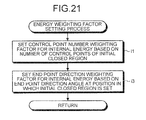
- FIG. 21 is a flowchart illustrating the detailed processing sequence of the energy weighing factor setting process according to the second embodiment.
- the control point number weighting factor setting unit 291 sets the control point number weighting factor for the internal energy based on the number of control points of the initial closed region (Step i 1 ). This can be realized by a process similar to that of Step d 1 illustrated in FIG. 14 .
- the end point direction weighting factor setting unit 293 a sets an end point direction weighting factor for the internal energy based on the end point direction angle calculated for the center as the center position of the initial closed region (Step i 3 ).
- the end point direction angle at the center position of the initial closed region is large, there is a high possibility that an end point of an edge or an edge that largely bends is present on the periphery thereof.
- Step i 3 in order not to extract a closed region into which such an end point of an edge gets or a closed region having a boundary including an edge that largely bends, the end point direction weighting factor for the internal energy is set so as to have a larger value as the end point direction angle becomes larger in accordance with the following Equation (10).
- End Point Weighting Factor End Point Direction Angle at Center as Center Position ⁇ Predetermined Coefficient (10)
- Step g 15 the closed region extracting unit 22 a performs a closed region extracting process.
- the energy weighted-sum calculating unit 31 extracts a closed region by acquiring a minimum value of the weighted sum of the internal energy weighted by the control point number weighting factor and the end point direction weighting factor set in the energy weighting factor setting process illustrated in FIG. 21 , the image energy, and the external energy.
- the initial closed region setting unit 23 a determines whether or not there is a selectable candidate point within the set range. The determination here is performed similarly to Step a 17 illustrated in FIG. 7 described in the first embodiment.
- the process is returned to Step g 6 , and the closed region size determining unit 27 a selects a candidate point, for example, that has a largest pixel value in the distance image from among selectable candidate points.
- the process of Step g 7 and the subsequent processes are performed for the selected candidate point.
- the process proceeds to Step a 19 .
- an edge is extracted from an intraluminal image and detects the end points thereof. Then, an area acquired by excluding a pixel, at which the end point direction angle formed by the straight line joining the end point and the end point direction is small, having a high possibility that an end point of an edge or an edge that largely bends is present on the outside thereof is determined as the set range of the initial closed region. Then, a closed region is extracted by using an active contour extraction method while weighting the internal energy representing the degree of smoothness of the boundary of the closed region by the end point direction weighting factor, which is set to have a larger value as the end point direction angle at the center position of the initial closed region is larger. According to the second embodiment, advantages similar to those of the first embodiment can be acquired.
- a candidate point at which the end point direction angle calculated in Step h 7 illustrated in FIG. 19 is the smallest is selected from among the candidate points arranged within the set range.
- Step a 21 illustrated in FIG. 18 as described in the first embodiment, an initial closed region, for example, having a circular shape is set so as to include an area that is not extracted as the closed region.
- an evaluation value of each candidate point may be calculated in accordance with the following Equation (11), and the candidate points are sequentially selected from a candidate point having a highest evaluation value.
- the evaluation value of each pixel located in an area that is not extracted as the closed region may be calculated in accordance with the following Equation (11), and an initial closed region is set so as to have a pixel having a highest evaluation value as its center position.
- a distance image value is a pixel value of a pixel as an evaluation target in the distance image.
- Evaluation Value End Point Direction Angle ⁇ Predetermined Coefficient+Distance Image Value (11)
- the functional configuration illustrated in FIG. 17 is merely an example, and the functional configuration is not limited thereto.
- the range determining unit 25 a is configured so as to include the edge extracting unit 251 a , the end point detecting unit 252 a , and the direction calculating unit 253 a as illustrated in FIG. 17 .
- the range determining unit 25 a can determine the set range based on the end point direction
- the end point direction weighting factor setting unit 293 a of the energy weighting factor setting unit 29 a can set the end point direction weighting factor based on the end point direction
- the configuration is not limited to a configuration including the range determining unit 25 a.
- FIG. 22 is a block diagram illustrating the functional configuration of an image processing apparatus 1 b according to the third embodiment.
- the same reference numeral is assigned to the same configuration as that described in the first embodiment.
- the image processing apparatus 1 b according to the third embodiment includes an image acquiring unit 11 , an input unit 12 , a display unit 13 , a recording unit 14 b , a calculating unit 20 b , and a control unit 15 that controls the overall operation of the image processing apparatus 1 b.
- an image processing program 141 b used for detecting an abnormal portion from an intraluminal image by realizing the process according to the third embodiment is recorded.
- the calculation unit 20 b includes a gradient strength calculating unit 21 , a closed region extracting unit 22 b , and an abnormal portion detecting unit 32 .
- the closed region extracting unit 22 b includes an initial closed region setting unit 23 b , an energy weighting factor setting unit 29 b , an energy calculating unit 30 , and an energy weighted-sum calculating unit 31 .
- the initial closed region setting unit 23 b sets an initial closed region.
- This initial closed region setting unit 23 b includes a range determining unit 26 b , a closed region size determining unit 27 b , and a control point number determining unit 28 .
- the configurations of the range determining unit 26 b and the closed region size determining unit 27 b are different from those of the first embodiment.
- the range determining unit 26 b includes an edge extracting unit 261 b , a distance image calculating unit 262 b , a ridge detecting unit 263 b , and a ridge shape information calculating unit 264 b .
- the edge extracting unit 261 b extracts pixels of which the gradient strength is a predetermined value or more as an edge based on the gradient strength of each pixel of the intraluminal image.
- the distance image calculating unit 262 b calculates a distance image that represents a distance from the edge.
- the ridge detecting unit 263 b detects the ridge of a distance image.
- the ridge shape information calculating unit 264 b calculates the shape information of a ridge.
- This ridge shape information calculating unit 264 b includes a ridge curvature calculating unit 265 b that calculates the curvature of a ridge.
- the closed region size determining unit 27 b similarly to that of the first embodiment, determines the size of the initial closed region based on the set range of the initial closed region that is determined by the range determining unit 26 b .
- a ridge closed region size determining unit 272 b of the closed region size determining unit 27 b determines the size of an initial closed region to be set within the set range based on a distance from the edge to the ridge within the set range.
- the shape of the initial closed region is a circular shape, the shape is not limited thereto and may be an appropriate shape.
- the energy weighting factor setting unit 29 b sets a weighing factor for at least one energy among a plurality of energies calculated by the energy calculating unit 30 based on the position of the initial closed region.
- This energy weighting factor setting unit 29 b includes a control point number weighting factor setting unit 291 and a ridge shape weighting factor setting unit 294 b , and sets two types of weighting factor (a control point number weighting factor and a ridge shape weighting factor) as weighting factors for the internal energy.
- the ridge shape weighting factor setting unit 294 b sets a ridge shape weighting factor based on the shape information of a ridge at the position at which the initial closed region is set.
- FIG. 23 is the entire flowchart illustrating the processing sequence performed by the image processing apparatus 1 b according to the third embodiment.
- the process described here is realized by executing the image processing program 141 b recorded in the recording unit 14 b by using the calculating unit 20 b .
- the same reference numeral is assigned to the same process as that of the first embodiment in FIG. 23 .
- FIG. 24 is a flowchart illustrating the detailed processing sequence of the set range determining process according to the third embodiment.
- the edge extracting unit 261 b extracts a pixel of which the value of the gradient strength is, for example, a threshold value set in advance or more from the intraluminal image as the processing target as an edge based on the gradient strength calculated for each pixel in Step a 3 illustrated in FIG. 23 (Step k 1 ).
- This can be realized by using a known edge extracting technique such as Canny or Harris.
- the distance image calculating unit 262 b calculates a distance to the edge extracted in Step k 1 for each pixel and generates a distance image in which the pixel value of each pixel is set to the value of the distance calculated for the corresponding pixel (Step k 3 ). Then, the ridge detecting unit 263 b detects a ridge of the distance image (Step k 5 ). For example, this can be realized by applying a skeleton extracting process or the like.
- the ridge curvature calculating unit 265 b calculates the curvature of the ridge, which is calculated in Step k 5 , as the shape information of the ridge.
- the ridge curvature calculating unit 265 b arranges a plurality of candidate points on the ridge so as to be equally spaced (Step k 7 ).
- the ridge curvature calculating unit 265 b calculates an inner product of two adjacent candidate points of each candidate point arranged in Step k 7 and sets the inner product as the curvature of the ridge (Step k 9 ).
- the range determining unit 26 b performs threshold value processing for the curvature calculated for each candidate point in Step k 9 . Then, the range determining unit 26 b selects candidate points at which the curvature is a threshold value set in advance or less and determines the range of the selected candidate points as a set range of the initial closed region (Step k 11 ).
- Step j 6 the process of Steps k 3 to k 11 is performed for each area so as to determine the set range of each initial closed region.
- the process is returned to Step j 5 illustrated in FIG. 23 and thereafter proceeds to Step j 6 .
- the ridge closed region size determining unit 272 b selects one candidate point from among the candidate points arranged within the set range determined in Step k 7 illustrated in FIG. 24 .
- a candidate point of which the pixel value in the distance image is the largest is selected based on the pixel value of each candidate point (pixel) within the set range in the distance image generated in Step k 3 illustrated in FIG. 24 .
- the method of selecting a candidate point is not particularly limited, and a method may be used in which a candidate point is randomly selected from among candidate points arranged within the set range.
- the ridge closed region size determining unit 272 b calculates a radius r of a circular area having the position of the candidate point selected in Step j 6 as its center position so as to be set as the size of the initial closed region (Step j 7 ).
- the radius r is set based on a distance from the center position of the initial closed region to the edge such that the value of the radius r is larger as the distance becomes longer.
- the initial closed region setting unit 23 b sets the position of the candidate point selected in Step j 6 as the center position and sets a circular area of a radius r that is calculated for the corresponding center position in Step j 7 as the initial closed region (Step j 9 ).
- the control point number determining unit 28 determines the number of control points of the initial closed region by performing a control point number determining process (see FIG. 13 ) (Step a 11 ). Then, in the following Step j 13 , the energy weighting factor setting unit 29 b sets a control point number weighing factor and a ridge shape weighting factor for the initial closed region by performing an energy weighting factor setting process.
- FIG. 25 is a flowchart illustrating the detailed processing sequence of the energy weighing factor setting process according to the third embodiment.
- the control point number weighting factor setting unit 291 sets the control point number weighting factor for the internal energy based on the number of control points of the initial closed region (Step 11 ). This can be realized by a process similar to that of Step d 1 illustrated in FIG. 14 .
- the ridge shape weighting factor setting unit 294 b sets a ridge shape weighting factor for the internal energy based on the shape information (the curvature of a ridge that is calculated in Step k 9 illustrated in FIG. 24 for the candidate point as the center position) of a ridge at the center position of the initial closed region (Step 13 ).
- the ridge is detected as a pixel position that is located far from the edge position located inside the intraluminal image.
- Step 13 in order not to extract a closed region into which an end point of an edge gets or a closed region having a boundary including an edge that largely bends, the ridge shape weighting factor for the internal energy is set so as to have a larger value as the ridge shape information (the curvature of the ridge at the position of the candidate point as the center position) becomes larger in accordance with the following Equation (12).
- Ridge Shape Weighting Factor Curvature of Ridge at Candidate Point as Center Position ⁇ Predetermined Coefficient (12)
- Step j 15 the closed region extracting unit 22 b performs a closed region extracting process.
- the energy weighted-sum calculating unit 31 extracts a closed region by acquiring a minimum value of the weighted sum of the internal energy weighted by the control point number weighting factor and the ridge shape weighting factor set in the energy weighting factor setting process illustrated in FIG. 25 , the image energy, and the external energy.
- the initial closed region setting unit 23 b determines whether or not there is a selectable candidate point within the set range. The determination here is performed similarly to Step a 17 illustrated in FIG. 7 described in the first embodiment.
- the process is returned to Step j 6 , and the ridge closed region size determining unit 272 b selects a candidate point, for example, that has a largest pixel value in the distance image from among selectable candidate points.
- the process proceeds to Step a 19 .
- a ridge located far from the edge is detected, a set range of the initial closed region is determined based on the curvature thereof, and the ridge shape weighting factor for the internal energy is set. According to this third embodiment, the advantages similar to those of the first embodiment can be acquired.
- candidate points are selected based on the pixel value of each candidate point within the set range in the distance image sequentially starting from a candidate point having a largest pixel value in the distance image.
- an initial closed region for example, having a circular shape is set so as to include an area that is not extracted as the closed region.
- an evaluation value of each candidate point may be calculated in accordance with the following Equation (13), and the candidate points are sequentially selected starting from a candidate point having a highest evaluation value, described in more detail, sequentially selected from a candidate point having a largest pixel value in the distance image on the ridge.
- the evaluation value of each pixel located in an area that is not extracted as the closed region may be calculated in accordance with the following Equation (13), and an initial closed region is set so as to have a pixel having a highest evaluation value as its center position.
- the functional configuration illustrated in FIG. 22 is merely an example, and the functional configuration is not limited thereto.
- the range determining unit 26 b is configured so as to include the edge extracting unit 261 b , the distance image calculating unit 262 b , the ridge detecting unit 263 b , and the ridge shape information calculating unit 264 b as illustrated in FIG. 22 .
- the range determining unit 26 b can determine a set range based on the shape information of the ridge
- the ridge shape weighting factor setting unit 294 b of the energy weighting factor setting unit 29 b can set the ridge shape weighting factor based on the shape information of the ridge
- the configuration is not limited to a configuration including the range determining unit 26 b.
- the image processing apparatus 1 according to the first embodiment, the image processing apparatus 1 a according to the second embodiment, and the image processing apparatus 1 b according to the third embodiment described above can be realized by executing a program prepared in advance by using a computer system such as a personal computer or a workstation.
- a computer system such as a personal computer or a workstation.
- a computer system that has the same functions as those of the image processing apparatuses 1 , 1 a , and 1 b described in the first to third embodiments and executes the image processing program 141 , 141 a , or 141 b will be described.
- FIG. 26 is a system configuration diagram illustrating the configuration of a computer system 400 according to this modified example
- FIG. 27 is a block diagram illustrating the configuration of a main body unit 410 of the computer system 400
- the computer system 400 includes a main body unit 410 , a display 420 that is used for displaying information such as an image on a display screen 421 in accordance with an instruction transmitted from the main body unit 410 , a keyboard 430 that is used for inputting various types of information to the computer system 400 , and a mouse 440 that is used for designating an arbitrary position on the display screen 421 of the display 420 .
- the main body unit 410 of this computer system 400 includes a CPU 411 , a RAM 412 , a ROM 413 , a hard disk drive (HDD) 414 , a CD-ROM drive 415 that accepts a CD-ROM 460 , a USB port 416 to which a USB memory 470 can be detachably connected, an I/O interface 417 that connects the display 420 , the keyboard 430 , and the mouse 440 together, and a LAN interface 418 that is used for being connected to a local area network or a wide area network (LAN/WAN) N 1 .
- LAN/WAN wide area network
- a modem 450 that is used for being connected to a public circuit N 3 such as the Internet is connected, and a personal computer (PC) 481 as another computer system, a server 482 , a printer 483 , and the like are connected through the LAN interface 418 and the local area network or the wide area network N 1 .
- PC personal computer
- This computer system 400 realizes the image processing apparatus (for example, the image processing apparatus 1 according to the first embodiment, the image processing apparatus 1 a according to the second embodiment, or the image processing apparatus 1 b according to the third embodiment) by reading out and executing an image processing program (for example, the image processing program 141 according to the first embodiment, the image processing program 141 a according to the second embodiment, or the image processing program 141 b according to the third embodiment) stored on a recording medium.
- an image processing program for example, the image processing program 141 according to the first embodiment, the image processing program 141 a according to the second embodiment, or the image processing program 141 b according to the third embodiment
- the recording media includes all types of recording media on which an image processing program is recorded so as to be readable by using the computer system 400 such as “portable-type physical media” including an MO disc, a DVD disc, a flexible disc, (FD), an IC card, and the like in addition to a CD-ROM 460 and a USB memory 470 , “fixed-type physical media” including an HDD 414 , a RAM 412 , a ROM 413 , and the like that can be internally or externally included in the computer system 400 , and “communication media” such as a public circuit N 3 that is connected through the modem 450 , a local area network or a wide area network N 1 to which the PC 481 as another computer system or the server 482 is connected, and the like that store a program for a short time when the program is transmitted.
- “portable-type physical media” including an MO disc, a DVD disc, a flexible disc, (FD), an IC card, and the like in addition to a CD-ROM 460 and
- the image processing program is recorded on a recording medium such as a “portable-type physical medium”, a “fixed-type physical medium”, or a “communication medium” in a computer-readable form, and the image processing apparatus is realized by reading out the image processing program from such a recording medium and executing the image processing program by using the computer system 400 .
- the image processing program is not limited as being executed by the computer system 400 , and the present invention can be similarly applied to a case where the PC 481 as another computer system or the server 482 executes the image processing program or a case where the PC 481 and the server 482 cooperatively execute the image processing program.
- the present invention is not limited to the first to third embodiments and modified examples thereof described above, and various inventions can be configured by appropriately combining a plurality of constituent elements disclosed in the embodiments.
- a configuration may be employed in which several constituent elements are excluded from all the constituent elements illustrated in each embodiment or a modified example.
- the constituent elements illustrated in other embodiments or other modified examples may be appropriately combined.
- an abnormal portion can be detected from an intraluminal image with high accuracy.
Landscapes
- Engineering & Computer Science (AREA)
- Theoretical Computer Science (AREA)
- Computer Vision & Pattern Recognition (AREA)
- Physics & Mathematics (AREA)
- General Physics & Mathematics (AREA)
- Health & Medical Sciences (AREA)
- Software Systems (AREA)
- General Health & Medical Sciences (AREA)
- Medical Informatics (AREA)
- Nuclear Medicine, Radiotherapy & Molecular Imaging (AREA)
- Radiology & Medical Imaging (AREA)
- Quality & Reliability (AREA)
- Image Analysis (AREA)
- Endoscopes (AREA)
- Image Processing (AREA)
Applications Claiming Priority (2)
| Application Number | Priority Date | Filing Date | Title |
|---|---|---|---|
| JP2010187678A JP5620194B2 (ja) | 2010-08-24 | 2010-08-24 | 画像処理装置、画像処理方法、および画像処理プログラム |
| JP2010-187678 | 2010-08-24 |
Publications (2)
| Publication Number | Publication Date |
|---|---|
| US20120051654A1 US20120051654A1 (en) | 2012-03-01 |
| US8620042B2 true US8620042B2 (en) | 2013-12-31 |
Family
ID=44650834
Family Applications (1)
| Application Number | Title | Priority Date | Filing Date |
|---|---|---|---|
| US13/215,599 Active 2032-06-28 US8620042B2 (en) | 2010-08-24 | 2011-08-23 | Image processing apparatus, image processing method, and computer-readable recording medium |
Country Status (4)
| Country | Link |
|---|---|
| US (1) | US8620042B2 (zh) |
| EP (1) | EP2423875B1 (zh) |
| JP (1) | JP5620194B2 (zh) |
| CN (1) | CN102376092B (zh) |
Cited By (2)
| Publication number | Priority date | Publication date | Assignee | Title |
|---|---|---|---|---|
| US9672610B2 (en) | 2012-11-29 | 2017-06-06 | Olympus Corporation | Image processing apparatus, image processing method, and computer-readable recording medium |
| US9928590B2 (en) | 2012-04-23 | 2018-03-27 | Olympus Corporation | Image processing apparatus, image processing method, and computer-readable recording device for determining whether candidate region is abnormality or residue |
Families Citing this family (7)
| Publication number | Priority date | Publication date | Assignee | Title |
|---|---|---|---|---|
| JP5570866B2 (ja) * | 2010-04-30 | 2014-08-13 | オリンパス株式会社 | 画像処理装置、画像処理装置の作動方法、および画像処理プログラム |
| JP5658945B2 (ja) * | 2010-08-24 | 2015-01-28 | オリンパス株式会社 | 画像処理装置、画像処理装置の作動方法、および画像処理プログラム |
| JP5620194B2 (ja) * | 2010-08-24 | 2014-11-05 | オリンパス株式会社 | 画像処理装置、画像処理方法、および画像処理プログラム |
| JP6265588B2 (ja) * | 2012-06-12 | 2018-01-24 | オリンパス株式会社 | 画像処理装置、画像処理装置の作動方法、及び画像処理プログラム |
| JP5593009B1 (ja) * | 2012-11-07 | 2014-09-17 | オリンパスメディカルシステムズ株式会社 | 医療用画像処理装置 |
| WO2014205632A1 (en) * | 2013-06-24 | 2014-12-31 | Adobe Systems Incorporated | Gravity point drawing method |
| CN107105988B (zh) | 2015-01-20 | 2019-02-05 | 奥林巴斯株式会社 | 图像处理装置、图像处理方法和记录介质 |
Citations (39)
| Publication number | Priority date | Publication date | Assignee | Title |
|---|---|---|---|---|
| US5239591A (en) * | 1991-07-03 | 1993-08-24 | U.S. Philips Corp. | Contour extraction in multi-phase, multi-slice cardiac mri studies by propagation of seed contours between images |
| US5487116A (en) * | 1993-05-25 | 1996-01-23 | Matsushita Electric Industrial Co., Ltd. | Vehicle recognition apparatus |
| JP2002099896A (ja) | 2000-09-22 | 2002-04-05 | Fuji Photo Film Co Ltd | 異常陰影候補検出方法および装置 |
| US20020062061A1 (en) * | 1997-09-24 | 2002-05-23 | Olympus Optical Co., Ltd. | Fluorescent imaging device |
| US20020063893A1 (en) * | 2000-11-29 | 2002-05-30 | Omron Corporation | Image processing method and apparatus |
| US20020118875A1 (en) * | 2000-12-21 | 2002-08-29 | Wilensky Gregg D. | Image extraction from complex scenes in digital video |
| US20030036751A1 (en) * | 2001-05-30 | 2003-02-20 | Anderson R. Rox | Apparatus and method for laser treatment with spectroscopic feedback |
| US20030139650A1 (en) * | 2002-01-18 | 2003-07-24 | Hiroyuki Homma | Endoscope |
| US6631206B1 (en) * | 1999-08-30 | 2003-10-07 | University Of Washington | Image filtering in HSI color space |
| US6678416B1 (en) * | 2000-02-08 | 2004-01-13 | University Of Washington | Detecting and segmenting local deformation in a tracked video object |
| US6728401B1 (en) * | 2000-08-17 | 2004-04-27 | Viewahead Technology | Red-eye removal using color image processing |
| US20040218916A1 (en) * | 2003-03-25 | 2004-11-04 | Hiroshi Yamaguchi | Automatic photography system |
| US20050129296A1 (en) * | 2003-12-15 | 2005-06-16 | Henri Setala | Method and system for detecting a fiducial in digital projection images |
| US6912310B1 (en) * | 1999-06-10 | 2005-06-28 | University Of Washington | Video object segmentation using active contour model with directional information |
| US20060159341A1 (en) * | 2003-06-13 | 2006-07-20 | Vladimir Pekar | 3D image segmentation |
| US20070230767A1 (en) * | 2004-07-09 | 2007-10-04 | Intellectual Property Bank Corp. | Method for Displaying Bioinformation Using Millimeter-Wave Band Electromagnetic Wave, Device for Acquiring and Displaying Bioinformation |
| US20070260214A1 (en) * | 2006-01-13 | 2007-11-08 | Olympus Medical Systems Corp. | Medical procedure through natural body opening |
| US20080040083A1 (en) * | 2006-08-14 | 2008-02-14 | Siemens Corporate Research, Inc. | System and Method for Solid Component Evaluation in Mixed Ground Glass Nodules |
| US20080181481A1 (en) * | 2006-12-11 | 2008-07-31 | Siemens Corporation Research, Inc. | Method and System for Locating Opaque Regions in Chest X-Ray Radiographs |
| US20080240526A1 (en) * | 2007-03-28 | 2008-10-02 | Suri Jasjit S | Object recognition system for medical imaging |
| US20090196476A1 (en) * | 2006-08-08 | 2009-08-06 | Olympus Medical Systems Corp. | Medical image processing device and medical image processing method |
| US20090202124A1 (en) * | 2006-10-11 | 2009-08-13 | Olympus Corporation | Image processing apparatus, image processing method, and computer program product |
| WO2009154125A1 (ja) | 2008-06-17 | 2009-12-23 | オリンパス株式会社 | 画像処理装置、画像処理プログラムおよび画像処理方法 |
| US7646902B2 (en) * | 2005-02-08 | 2010-01-12 | Regents Of The University Of Michigan | Computerized detection of breast cancer on digital tomosynthesis mammograms |
| US20100067742A1 (en) * | 2008-09-12 | 2010-03-18 | Sony Corporation | Object detecting device, imaging apparatus, object detecting method, and program |
| US20100092055A1 (en) * | 2007-06-14 | 2010-04-15 | Olympus Corporation | Image processing apparatus, image processing program product, and image processing method |
| US20100134517A1 (en) * | 2007-05-22 | 2010-06-03 | Manale Saikaly | Method for automatic boundary segmentation of object in 2d and/or 3d image |
| US20100166283A1 (en) * | 2008-12-30 | 2010-07-01 | Stefan Grosskopf | Method for determining a 2d contour of a vessel structure imaged in 3d image data |
| US20100177957A1 (en) * | 2009-01-09 | 2010-07-15 | Sony Corporation | Object detecting device, learning device, object detecting method, and program |
| US20110002522A1 (en) * | 2008-02-25 | 2011-01-06 | Yoshihiro Goto | Medical imaging processing device, medical image processing method, and program |
| US20110019886A1 (en) * | 2009-07-27 | 2011-01-27 | Fujifilm Corporation | Medical image processing apparatus, method, and program |
| US20110158474A1 (en) * | 2009-12-31 | 2011-06-30 | Indian Institute Of Technology Bombay | Image object tracking and segmentation using active contours |
| US20110176730A1 (en) * | 2010-01-15 | 2011-07-21 | Olympus Corporation | Image processing device, endoscope system, program, and image processing method |
| US20110181614A1 (en) * | 2010-01-25 | 2011-07-28 | King Jen Chang | Quantification method of the feature of a tumor and an imaging method of the same |
| US20110274321A1 (en) * | 2010-04-30 | 2011-11-10 | Olympus Corporation | Image processing apparatus, image processing method, and computer-readable recording medium |
| US20120051654A1 (en) * | 2010-08-24 | 2012-03-01 | Olympus Corporation | Image processing apparatus, image processing method, and computer-readable recording medium |
| US20120051612A1 (en) * | 2010-08-24 | 2012-03-01 | Olympus Corporation | Image processing apparatus, image processing method, and computer-readable recording medium |
| US8180154B2 (en) * | 2008-03-25 | 2012-05-15 | Techfinity, Inc. | Method and apparatus for region-based segmentation image processing using region mapping |
| US20120230572A1 (en) * | 2011-03-10 | 2012-09-13 | Siemens Molecular Imaging Limited | Method and System for Multi-Organ Segmentation Using Learning-Based Segmentation and Level Set Optimization |
Family Cites Families (5)
| Publication number | Priority date | Publication date | Assignee | Title |
|---|---|---|---|---|
| DE69429743T2 (de) * | 1993-06-29 | 2002-10-02 | Koninkl Philips Electronics Nv | Verfahren und Gerät zur Bestimmung einer Kontur in einem durch eine Dichteverteilung gekennzeichneten Raum |
| JP2000331143A (ja) * | 1999-05-14 | 2000-11-30 | Mitsubishi Electric Corp | 画像処理方法 |
| JP2004187998A (ja) * | 2002-12-12 | 2004-07-08 | Fuji Photo Film Co Ltd | 異常陰影形状抽出装置 |
| JP4305431B2 (ja) * | 2005-09-06 | 2009-07-29 | ソニー株式会社 | 画像処理装置、マスク作成方法及びプログラム |
| JP4644794B2 (ja) * | 2006-03-30 | 2011-03-02 | 株式会社日立メディコ | 画像認識装置 |
-
2010
- 2010-08-24 JP JP2010187678A patent/JP5620194B2/ja active Active
-
2011
- 2011-08-22 EP EP11006850A patent/EP2423875B1/en not_active Not-in-force
- 2011-08-23 US US13/215,599 patent/US8620042B2/en active Active
- 2011-08-24 CN CN201110245636.9A patent/CN102376092B/zh not_active Expired - Fee Related
Patent Citations (44)
| Publication number | Priority date | Publication date | Assignee | Title |
|---|---|---|---|---|
| US5239591A (en) * | 1991-07-03 | 1993-08-24 | U.S. Philips Corp. | Contour extraction in multi-phase, multi-slice cardiac mri studies by propagation of seed contours between images |
| US5487116A (en) * | 1993-05-25 | 1996-01-23 | Matsushita Electric Industrial Co., Ltd. | Vehicle recognition apparatus |
| US20020062061A1 (en) * | 1997-09-24 | 2002-05-23 | Olympus Optical Co., Ltd. | Fluorescent imaging device |
| US6912310B1 (en) * | 1999-06-10 | 2005-06-28 | University Of Washington | Video object segmentation using active contour model with directional information |
| US6631206B1 (en) * | 1999-08-30 | 2003-10-07 | University Of Washington | Image filtering in HSI color space |
| US6678416B1 (en) * | 2000-02-08 | 2004-01-13 | University Of Washington | Detecting and segmenting local deformation in a tracked video object |
| US6728401B1 (en) * | 2000-08-17 | 2004-04-27 | Viewahead Technology | Red-eye removal using color image processing |
| JP2002099896A (ja) | 2000-09-22 | 2002-04-05 | Fuji Photo Film Co Ltd | 異常陰影候補検出方法および装置 |
| US20020063893A1 (en) * | 2000-11-29 | 2002-05-30 | Omron Corporation | Image processing method and apparatus |
| US20020118875A1 (en) * | 2000-12-21 | 2002-08-29 | Wilensky Gregg D. | Image extraction from complex scenes in digital video |
| US20030036751A1 (en) * | 2001-05-30 | 2003-02-20 | Anderson R. Rox | Apparatus and method for laser treatment with spectroscopic feedback |
| US20030139650A1 (en) * | 2002-01-18 | 2003-07-24 | Hiroyuki Homma | Endoscope |
| US20040218916A1 (en) * | 2003-03-25 | 2004-11-04 | Hiroshi Yamaguchi | Automatic photography system |
| US6996340B2 (en) * | 2003-03-25 | 2006-02-07 | Fuji Photo Film Co., Ltd. | Automatic photography system |
| US20060159341A1 (en) * | 2003-06-13 | 2006-07-20 | Vladimir Pekar | 3D image segmentation |
| US7536041B2 (en) * | 2003-06-13 | 2009-05-19 | Koninklijke Philips Electronics N.V. | 3D image segmentation |
| US20050129296A1 (en) * | 2003-12-15 | 2005-06-16 | Henri Setala | Method and system for detecting a fiducial in digital projection images |
| US20070230767A1 (en) * | 2004-07-09 | 2007-10-04 | Intellectual Property Bank Corp. | Method for Displaying Bioinformation Using Millimeter-Wave Band Electromagnetic Wave, Device for Acquiring and Displaying Bioinformation |
| US20100104154A1 (en) * | 2005-02-08 | 2010-04-29 | The Regents Of The University Of Michigan | Computerized Detection of Breast Cancer on Digital Tomosynthesis Mamograms |
| US7646902B2 (en) * | 2005-02-08 | 2010-01-12 | Regents Of The University Of Michigan | Computerized detection of breast cancer on digital tomosynthesis mammograms |
| US20070260214A1 (en) * | 2006-01-13 | 2007-11-08 | Olympus Medical Systems Corp. | Medical procedure through natural body opening |
| US20090196476A1 (en) * | 2006-08-08 | 2009-08-06 | Olympus Medical Systems Corp. | Medical image processing device and medical image processing method |
| US20080040083A1 (en) * | 2006-08-14 | 2008-02-14 | Siemens Corporate Research, Inc. | System and Method for Solid Component Evaluation in Mixed Ground Glass Nodules |
| US20090202124A1 (en) * | 2006-10-11 | 2009-08-13 | Olympus Corporation | Image processing apparatus, image processing method, and computer program product |
| US8103077B2 (en) * | 2006-12-11 | 2012-01-24 | Siemens Aktiengesellschaft | Method and system for locating opaque regions in chest X-ray radiographs |
| US20080181481A1 (en) * | 2006-12-11 | 2008-07-31 | Siemens Corporation Research, Inc. | Method and System for Locating Opaque Regions in Chest X-Ray Radiographs |
| US20080240526A1 (en) * | 2007-03-28 | 2008-10-02 | Suri Jasjit S | Object recognition system for medical imaging |
| US20100134517A1 (en) * | 2007-05-22 | 2010-06-03 | Manale Saikaly | Method for automatic boundary segmentation of object in 2d and/or 3d image |
| US20100092055A1 (en) * | 2007-06-14 | 2010-04-15 | Olympus Corporation | Image processing apparatus, image processing program product, and image processing method |
| US20110002522A1 (en) * | 2008-02-25 | 2011-01-06 | Yoshihiro Goto | Medical imaging processing device, medical image processing method, and program |
| US8180154B2 (en) * | 2008-03-25 | 2012-05-15 | Techfinity, Inc. | Method and apparatus for region-based segmentation image processing using region mapping |
| WO2009154125A1 (ja) | 2008-06-17 | 2009-12-23 | オリンパス株式会社 | 画像処理装置、画像処理プログラムおよび画像処理方法 |
| EP2305091A1 (en) | 2008-06-17 | 2011-04-06 | Olympus Corporation | Image processing apparatus, image processing program, and image processing method |
| US20100067742A1 (en) * | 2008-09-12 | 2010-03-18 | Sony Corporation | Object detecting device, imaging apparatus, object detecting method, and program |
| US20100166283A1 (en) * | 2008-12-30 | 2010-07-01 | Stefan Grosskopf | Method for determining a 2d contour of a vessel structure imaged in 3d image data |
| US20100177957A1 (en) * | 2009-01-09 | 2010-07-15 | Sony Corporation | Object detecting device, learning device, object detecting method, and program |
| US20110019886A1 (en) * | 2009-07-27 | 2011-01-27 | Fujifilm Corporation | Medical image processing apparatus, method, and program |
| US20110158474A1 (en) * | 2009-12-31 | 2011-06-30 | Indian Institute Of Technology Bombay | Image object tracking and segmentation using active contours |
| US20110176730A1 (en) * | 2010-01-15 | 2011-07-21 | Olympus Corporation | Image processing device, endoscope system, program, and image processing method |
| US20110181614A1 (en) * | 2010-01-25 | 2011-07-28 | King Jen Chang | Quantification method of the feature of a tumor and an imaging method of the same |
| US20110274321A1 (en) * | 2010-04-30 | 2011-11-10 | Olympus Corporation | Image processing apparatus, image processing method, and computer-readable recording medium |
| US20120051654A1 (en) * | 2010-08-24 | 2012-03-01 | Olympus Corporation | Image processing apparatus, image processing method, and computer-readable recording medium |
| US20120051612A1 (en) * | 2010-08-24 | 2012-03-01 | Olympus Corporation | Image processing apparatus, image processing method, and computer-readable recording medium |
| US20120230572A1 (en) * | 2011-03-10 | 2012-09-13 | Siemens Molecular Imaging Limited | Method and System for Multi-Organ Segmentation Using Learning-Based Segmentation and Level Set Optimization |
Non-Patent Citations (4)
| Title |
|---|
| European Search Report dated Dec. 20, 2012 from corresponding European Application Publication No. 11 00 6850.9. |
| Jin, H. and Kobatake, H., "Extraction of Microcalcifications on Mammogram Using Morphological Filter with Multiple Structuring Elements", The Transactions of the Institute of Electronics, Information and Communication Engineers, Jul. 1992, D-II , vol. J75-D-II, No. 7, pp. 1170-1176 together with English language abstract. |
| Kobatake, H. et al., "Basic Theory of Mathematical Morphology and Its Application to Mammogram Processing", Medical Imaging Technology, Jan. 1994, vol. 12, No. 1, pp. 59-66 together with English language abstract. |
| Liang, J. et al., "Interactive Medical Image Segmentation with United Snakes", Jan. 1, 2006, Medical Image Computing and Computer Assisted Intervention-Miccai '99: Second International Conference, Cambridge, UK, Sep. 19-22, 1999, pp. 116-127. |
Cited By (2)
| Publication number | Priority date | Publication date | Assignee | Title |
|---|---|---|---|---|
| US9928590B2 (en) | 2012-04-23 | 2018-03-27 | Olympus Corporation | Image processing apparatus, image processing method, and computer-readable recording device for determining whether candidate region is abnormality or residue |
| US9672610B2 (en) | 2012-11-29 | 2017-06-06 | Olympus Corporation | Image processing apparatus, image processing method, and computer-readable recording medium |
Also Published As
| Publication number | Publication date |
|---|---|
| JP2012045055A (ja) | 2012-03-08 |
| CN102376092B (zh) | 2015-10-28 |
| EP2423875A1 (en) | 2012-02-29 |
| EP2423875B1 (en) | 2013-04-03 |
| US20120051654A1 (en) | 2012-03-01 |
| CN102376092A (zh) | 2012-03-14 |
| JP5620194B2 (ja) | 2014-11-05 |
Similar Documents
| Publication | Publication Date | Title |
|---|---|---|
| US8620042B2 (en) | Image processing apparatus, image processing method, and computer-readable recording medium | |
| US8811698B2 (en) | Image processing apparatus, image processing method, and computer-readable recording medium | |
| US8620043B2 (en) | Image processing apparatus, image processing method, and computer-readable recording medium | |
| US8989467B2 (en) | Image processing apparatus, method and computer readable recording medium for detecting abnormal area based on difference between pixel value and reference surface | |
| US9053533B2 (en) | Image processing apparatus, image processing method, and computer-readable recording medium for extracting a dark portion area from an intraluminal image | |
| US8705818B2 (en) | Image processing device, computer readable storage medium storing image processing program, and image processing method | |
| JP5683888B2 (ja) | 画像処理装置、画像処理方法、および画像処理プログラム | |
| US8107704B2 (en) | Image processing device, image processing program and image processing method | |
| CN113573654A (zh) | 用于检测并测定病灶尺寸的ai系统 | |
| US9672610B2 (en) | Image processing apparatus, image processing method, and computer-readable recording medium | |
| US20110069876A1 (en) | Image processing apparatus, image processing program recording medium, and image processing method | |
| JP5526044B2 (ja) | 画像処理装置、画像処理方法、及び画像処理プログラム | |
| US10178941B2 (en) | Image processing apparatus, image processing method, and computer-readable recording device | |
| JP6578058B2 (ja) | 画像処理装置、画像処理装置の作動方法及び画像処理装置の作動プログラム | |
| US8774521B2 (en) | Image processing apparatus, image processing method, and computer-readable recording device | |
| JP2006102091A (ja) | 乳房画像位置合わせ装置およびそのプログラム | |
| JP2005211439A (ja) | 異常陰影表示装置およびそのプログラム | |
| JP3807541B2 (ja) | 乳房画像表示方法および装置 | |
| CN117456282B (zh) | 一种针对消化内镜的胃部萎缩分型检测方法和系统 | |
| JPWO2016056408A1 (ja) | 画像処理装置、画像処理方法、及び画像処理プログラム |
Legal Events
| Date | Code | Title | Description |
|---|---|---|---|
| AS | Assignment |
Owner name: OLYMPUS CORPORATION, JAPAN Free format text: ASSIGNMENT OF ASSIGNORS INTEREST;ASSIGNORS:KITAMURA, MAKOTO;KANDA, YAMATO;MATSUDA, TAKEHIRO;AND OTHERS;REEL/FRAME:026792/0627 Effective date: 20110727 |
|
| STCF | Information on status: patent grant |
Free format text: PATENTED CASE |
|
| FEPP | Fee payment procedure |
Free format text: PAYOR NUMBER ASSIGNED (ORIGINAL EVENT CODE: ASPN); ENTITY STATUS OF PATENT OWNER: LARGE ENTITY |
|
| AS | Assignment |
Owner name: OLYMPUS CORPORATION, JAPAN Free format text: CHANGE OF ADDRESS;ASSIGNOR:OLYMPUS CORPORATION;REEL/FRAME:039344/0502 Effective date: 20160401 |
|
| FPAY | Fee payment |
Year of fee payment: 4 |
|
| MAFP | Maintenance fee payment |
Free format text: PAYMENT OF MAINTENANCE FEE, 8TH YEAR, LARGE ENTITY (ORIGINAL EVENT CODE: M1552); ENTITY STATUS OF PATENT OWNER: LARGE ENTITY Year of fee payment: 8 |