US8471622B2 - Drive circuit of semiconductor device - Google Patents
Drive circuit of semiconductor device Download PDFInfo
- Publication number
- US8471622B2 US8471622B2 US12/760,742 US76074210A US8471622B2 US 8471622 B2 US8471622 B2 US 8471622B2 US 76074210 A US76074210 A US 76074210A US 8471622 B2 US8471622 B2 US 8471622B2
- Authority
- US
- United States
- Prior art keywords
- power semiconductor
- switching device
- semiconductor switching
- diode
- side terminal
- Prior art date
- Legal status (The legal status is an assumption and is not a legal conclusion. Google has not performed a legal analysis and makes no representation as to the accuracy of the status listed.)
- Expired - Fee Related
Links
Images


Classifications
-
- H—ELECTRICITY
- H03—ELECTRONIC CIRCUITRY
- H03K—PULSE TECHNIQUE
- H03K17/00—Electronic switching or gating, i.e. not by contact-making and –breaking
- H03K17/08—Modifications for protecting switching circuit against overcurrent or overvoltage
- H03K17/081—Modifications for protecting switching circuit against overcurrent or overvoltage without feedback from the output circuit to the control circuit
- H03K17/0812—Modifications for protecting switching circuit against overcurrent or overvoltage without feedback from the output circuit to the control circuit by measures taken in the control circuit
- H03K17/08128—Modifications for protecting switching circuit against overcurrent or overvoltage without feedback from the output circuit to the control circuit by measures taken in the control circuit in composite switches
-
- H—ELECTRICITY
- H03—ELECTRONIC CIRCUITRY
- H03K—PULSE TECHNIQUE
- H03K17/00—Electronic switching or gating, i.e. not by contact-making and –breaking
- H03K17/12—Modifications for increasing the maximum permissible switched current
- H03K17/127—Modifications for increasing the maximum permissible switched current in composite switches
-
- H—ELECTRICITY
- H03—ELECTRONIC CIRCUITRY
- H03K—PULSE TECHNIQUE
- H03K17/00—Electronic switching or gating, i.e. not by contact-making and –breaking
- H03K17/51—Electronic switching or gating, i.e. not by contact-making and –breaking characterised by the components used
- H03K17/56—Electronic switching or gating, i.e. not by contact-making and –breaking characterised by the components used by the use, as active elements, of semiconductor devices
- H03K17/687—Electronic switching or gating, i.e. not by contact-making and –breaking characterised by the components used by the use, as active elements, of semiconductor devices the devices being field-effect transistors
- H03K17/6877—Electronic switching or gating, i.e. not by contact-making and –breaking characterised by the components used by the use, as active elements, of semiconductor devices the devices being field-effect transistors the control circuit comprising active elements different from those used in the output circuit
Landscapes
- Inverter Devices (AREA)
- Power Conversion In General (AREA)
- Electronic Switches (AREA)
Abstract
The invention provides a switching circuit of a power semiconductor device having connected in parallel SiC diodes with a small recovery current, capable of significantly reducing turn-on loss and recovery loss without increasing the noise in the MHz band, and contributing to reducing the loss and noise of inverters. The present invention provides a switching circuit and an inverter circuit of a power semiconductor device comprising a module combining Si-IGBT and SiC diodes, wherein an on-gate resistance is set smaller than an off-gate resistance.
Description
The present application is based on and claims priority of Japanese patent application No. 2009-100849 filed on Apr. 17, 2009, the entire contents of which are hereby incorporated by reference.
1. Field of the Invention
The present invention relates to a gate drive circuit of a power semiconductor module, comprising a power semiconductor switching device having connected thereto in parallel a freewheeling diode having a small reverse recovery current such as a Schottky barrier diode of a wide bandgap semiconductor such as SiC and GaN or a PiN diode of a wide bandgap semiconductor, and an inverter circuit comprising the same.
2. Description of the Related Art
For example, Japanese patent No. 3161589 (patent document 1) discloses an art of detecting the recovery current of a freewheeling diode, and switching the turn-on di/dt in two steps to thereby reduce both the turn-on loss and the surge voltage.
Further, Japanese patent No. 3941309 (patent document 2) discloses an art of controlling the turn-on gate drive speed in three steps (high speed, low speed, and high speed) so as to solve the problem of high dv/dt generated when the turn-on di/dt is set to high speed, which causes a noise in the range of over a few MHz and causes erroneous operation of peripheral devices, and to realize both noise reduction in the high frequency range and loss reduction.
As described above, according to the prior art IGBT inverter and the inventions disclosed in patent documents 1 and 2, attempts were made to reduce both the turn-on loss and the surge voltage or to reduce both the noise in the high frequency range and the loss by varying the gate charge speed. However, there were drawbacks according to the Si-PiN diode in which the recovery current became high when a large amount of current was conducted, and a large surge voltage was generated when a small current was conducted for a short period of time.
In order to solve such problems of the prior art, the present invention provides a drive circuit of a semiconductor device utilizing a Schottky barrier diode such as silicon carbide (SiC) and gallium nitride (GaN), which is a new wide bandgap semiconductor to be used instead of Si, to thereby drive the gate at high speed.
The present invention provides a gate drive circuit of a power semiconductor switching device comprising a power semiconductor switching device, and a freewheeling diode having a small reverse recovery current such as a Schottky barrier diode of a wide bandgap semiconductor such as SiC and GaN or a PiN diode of a wide bandgap semiconductor, wherein an on-gate resistance of the power semiconductor switching device is set smaller than an off-gate resistance thereof.
The gate drive circuit of the present invention further characterizes in that when the line inductance of the power semiconductor device and the gate drive circuit is denoted by Lg, a buried resistance of the power semiconductor device is denoted by Rgin, an input capacitance of the power semiconductor device is denoted by Cies (and an on-gate resistance of the power semiconductor switching device is denoted by Rgon, the gate resistance satisfies the following condition;
The present gate drive circuit also characterizes in that a capacitor is provided in parallel with the on-gate resistance of the power semiconductor switching device as a means for realizing high-speed driving.
The present invention further provides an inverter circuit comprising a power semiconductor switching device, a freewheeling diode having a small reverse recovery current such as a Schottky barrier diode of a wide bandgap semiconductor such as SiC and GaN or a PiN diode of a wide bandgap semiconductor, a power semiconductor module equipped with the power switching device and the freewheeling diode, and a gate drive circuit of the power semiconductor switching device, wherein a first high-voltage side terminal of the power semiconductor switching device of the power semiconductor module and a second high-voltage side terminal of the Schottky barrier diode of the wide bandgap semiconductor such as SiC and GaN are disposed independently, and an inductance is disposed between the first high-voltage side terminal and the second high-voltage side terminal.
According to the present invention, the gate drive speed of the power semiconductor module connected in parallel to a freewheeling diode having a small reverse recovery current such as a Schottky barrier diode of a wide bandgap semiconductor such as SiC or a PiN diode of a wide bandgap semiconductor is increased, so that the switching loss of the power semiconductor device is reduced, and as a result, the loss and the noise of the inverter can be reduced.
Now, the preferred embodiments for carrying out the present invention will be described with reference to the drawings.
The SiC-SBD 22 has a breakdown voltage strength as high as approximately 10 times that of Si, and therefore, a drift layer for ensuring pressure resistance can be reduced to approximately 1/10, so that the on-voltage of the power device can be reduced. Thus, SiC and other wide bandgap semiconductor devices can use unipolar devices even in high pressure resistance areas where Si semiconductor devices can only use bipolar devices.
In comparison with FIG. 6 , the present example has a recovery loss reduced to 1/10, and a turn-on loss reduced to ½. When the Si-PiN diode of FIG. 6 is adopted, speed-up causes di/dt of the reverse recovery of the PiN diode to be increased, which is multiplied with the main circuit inductance L to create a commutation surge (ΔVp=L×reverse recovery di/dt), and when the sum (E+ΔVp) of the power supply voltage (E) and the surge voltage (ΔVp) exceeds the withstand voltage of the power semiconductor switching device, the power semiconductor device may be damaged. On the other hand, when the SiC-SBD 22 is adopted, as shown by the solid line waveform, no reverse recovery current is generated by performing speed-up and no large surge voltage is caused in the recovery voltage, so that increase of speed becomes possible.
Further, the value of the on-gate resistance 11 should preferably be selected to satisfy a condition in which the gate circuit does not resonate. According to this condition, the circuit is an LRC resonant circuit in which an on-gate resistance (Rg11) 11 is connected in series with a gate line inductance (Lg) 10, an IGBT buried resistance (Rgin) 23 and an IGBT input capacitance (Cies) 24, wherein the circuit must satisfy a condition in which resonance does not occur. With respect to expression 1
having a following characteristic value
the condition for realizing overdamping in which gate vibration does not occur is
therefore, the on-gate resistance must satisfy expression (3).
In the present embodiment, the Si-IGBT is used as the switching device, but the switching device can be a MOSFET in the case of Si and can be a MOSFET, a junction FET or a bipolar transistor in the case of SiC. Moreover, the present embodiment adopts an SiC-SBD as the paralelly-connected diode, but similar effects can be achieved by adopting an SBD of a wide bandgap semiconductor such as GaN and diamond, a PiN diode, or a diode having an MPS (merged Schottky barrier) structure where an SBD and a PiN diode are combined.
When Lm is not provided, a frequency band near 9 MHz which is a vibrational frequency specific to SiC-SBD as shown in FIG. 4 was observed. This vibrational frequency is determined by the following expression;
On the other hand, when the
The condition of overdamping for avoiding this oscillation condition is represented by the following expression (6).
Therefore, by adopting the resonant frequency of expression (4) while satisfying expression (6), it becomes possible to drive the IGBT at high speed and reduce the loss significantly without influencing the noise in the MHz band, by additionally providing the inductance 31.
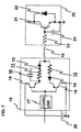
According to FIG. 11 , an inductance 32 is provided between the low-voltage side terminal 53 of the IGBT and the low-voltage side terminal 54 of the SiC-SBD, but also in this case, a low-loss and low-noise inverter can be realized by adopting the resonant frequency of expression (4) while satisfying expression (6).
Claims (4)
1. An inverter device comprising:
a power semiconductor switching device;
a freewheeling diode connected in parallel with the power semiconductor switching device, the freewheeling diode comprising a Schottky barrier diode of a wide bandgap semiconductor of SiC, GaN or diamond, a PiN diode, or a MPS diode in which a Schottky barrier diode and a PiN diode are combined; and
a gate drive circuit of the power semiconductor switching device,
wherein an on-gate resistance of the power semiconductor switching device is set smaller than an off-gate resistance thereof,
wherein when a line inductance of the power semiconductor switching device and the gate drive circuit is denoted by Lg, a buried resistance of the power semiconductor switching device is denoted by Rgin, an input capacitance of the power semiconductor switching device is denoted by Cies, and an on-gate resistance of the power, semiconductor switching device is denoted by Rgon, the following condition is satisfied:
and wherein a capacitor is provided in parallel with the on-gate resistance of the power semiconductor switching device.
2. An inverter device comprising:
a power semiconductor switching device;
a freewheeling diode connected in parallel with the power semiconductor switching device, the freewheeling diode comprising a Schottky barrier diode of a wide bandgap semiconductor of SiC, GaN or diamond, a PiN diode, or a MPS diode in which a Schottky barrier diode and a PiN diode are combined; and
a gate drive circuit of the power semiconductor switching device,
wherein a first high-voltage side terminal of the power semiconductor switching device and a second high-voltage side terminal of the freewheeling diode are disposed independently, and a first inductance is disposed between the first high-voltage side terminal and the second high-voltage side terminal, and
wherein a first low-voltage side terminal of the power semiconductor switching device and a second low-voltage side terminal of the freewheeling diode are disposed independently, and a second inductance is disposed between the first low-voltage side terminal and the second low-voltage side terminal.
3. The inverter device according to claim 2 , wherein when a sum of a parasitic inductance is denoted by Ls, an output capacitance of the power semiconductor switching device and the freewheeling diode is denoted by Coes, an on resistance of the power semiconductor switching device is denoted by Ron IGBT, and an inductance between the high-voltage side terminal of the power semiconductor switching device and the high-voltage side terminal of the freewheeling diode is denoted by Lm, Ron IGBT satisfies the following condition:
4. An inverter device comprising:
a power semiconductor switching device;
a freewheeling diode connected in parallel with the power semiconductor switching device, the freewheeling diode comprising a Schottky barrier diode of a wide bandgap semiconductor of SiC, GaN or diamond, a PiN diode, or a MPS diode in which a Schottky barrier diode and a PiN diode are combined; and
a gate drive circuit of the power semiconductor switching device,
wherein a first high-voltage side terminal of the power semiconductor switching device and a second high-voltage side terminal of the freewheeling diode are disposed independently, and a first inductance is disposed between the first high-voltage side terminal and the second high-voltage side terminal, and
wherein when a sum of a parasitic inductance is denoted by Ls, an output capacitance of the power semiconductor switching device and the freewheeling diode is denoted by Coes, an on resistance of the power semiconductor switching device is denoted by Ron IGBT, and an inductance between the high-voltage side terminal of the power semiconductor switching device and the high-voltage side terminal of the freewheeling diode is denoted by Lm, Ron IGBT satisfies the following condition:
Applications Claiming Priority (2)
| Application Number | Priority Date | Filing Date | Title |
|---|---|---|---|
| JP2009-100849 | 2009-04-17 | ||
| JP2009100849A JP5476028B2 (en) | 2009-04-17 | 2009-04-17 | Power semiconductor switching element gate drive circuit and inverter circuit |
Publications (2)
| Publication Number | Publication Date |
|---|---|
| US20100265746A1 US20100265746A1 (en) | 2010-10-21 |
| US8471622B2 true US8471622B2 (en) | 2013-06-25 |
Family
ID=42320566
Family Applications (1)
| Application Number | Title | Priority Date | Filing Date |
|---|---|---|---|
| US12/760,742 Expired - Fee Related US8471622B2 (en) | 2009-04-17 | 2010-04-15 | Drive circuit of semiconductor device |
Country Status (3)
| Country | Link |
|---|---|
| US (1) | US8471622B2 (en) |
| EP (1) | EP2242179B1 (en) |
| JP (1) | JP5476028B2 (en) |
Cited By (8)
| Publication number | Priority date | Publication date | Assignee | Title |
|---|---|---|---|---|
| US9543944B2 (en) * | 2013-03-08 | 2017-01-10 | Texas Instruments Incorporated | Driver for normally on III-nitride transistors to get normally-off functionality |
| US20170033790A1 (en) * | 2015-07-28 | 2017-02-02 | Toyota Jidosha Kabushiki Kaisha | Electric circuit |
| US20180138902A1 (en) * | 2016-11-14 | 2018-05-17 | Ford Global Technologies, Llc | Sensorless temperature compensation for power switching devices |
| US10171069B1 (en) | 2018-01-26 | 2019-01-01 | General Electric Company | Switch controller for adaptive reverse conduction control in switch devices |
| US10476495B2 (en) * | 2016-06-17 | 2019-11-12 | Nissan Motor Co., Ltd. | Drive device |
| US10644687B2 (en) * | 2018-03-28 | 2020-05-05 | Semikron Elektronik Gmbh & Co. Kg | Control device for power semiconductor switch |
| US11206016B2 (en) * | 2019-09-27 | 2021-12-21 | Analog Devices International Unlimited Company | Gate driver with pulsed gate slew control |
| US11923716B2 (en) | 2019-09-13 | 2024-03-05 | Milwaukee Electric Tool Corporation | Power converters with wide bandgap semiconductors |
Families Citing this family (29)
| Publication number | Priority date | Publication date | Assignee | Title |
|---|---|---|---|---|
| US9281776B2 (en) * | 2011-01-31 | 2016-03-08 | Mitsubishi Electric Corporation | Power conversion apparatus including different voltage-type bridge circuits |
| JP2013005511A (en) * | 2011-06-14 | 2013-01-07 | Sumitomo Electric Ind Ltd | Power module and power conversion circuit |
| JP5940281B2 (en) * | 2011-11-01 | 2016-06-29 | 株式会社東芝 | Gate drive circuit |
| JP5863442B2 (en) | 2011-12-22 | 2016-02-16 | 三菱電機株式会社 | Semiconductor module |
| JP6007578B2 (en) * | 2012-05-10 | 2016-10-12 | 富士電機株式会社 | Power semiconductor module and assembly method thereof |
| JP2014079086A (en) * | 2012-10-10 | 2014-05-01 | Fuji Electric Co Ltd | Circuit for driving voltage-driven semiconductor element |
| WO2014109304A1 (en) * | 2013-01-09 | 2014-07-17 | 株式会社 村田製作所 | Switching power supply device |
| JP6131084B2 (en) * | 2013-03-29 | 2017-05-17 | ローム株式会社 | Step-up DC / DC converter control circuit, control method, DC / DC converter and electronic device using the same, and vehicle |
| CN105453434A (en) * | 2013-04-17 | 2016-03-30 | 奥的斯电梯公司 | Drive unit employing gallium nitride switches |
| WO2015001618A1 (en) * | 2013-07-02 | 2015-01-08 | 三菱電機株式会社 | Backflow prevention device, power converter, and refrigerating and air-conditioning device |
| JP6101585B2 (en) * | 2013-07-18 | 2017-03-22 | 株式会社日立製作所 | Inverter device |
| JP6015615B2 (en) * | 2013-10-01 | 2016-10-26 | 三菱電機株式会社 | Semiconductor device |
| CN110634825B (en) * | 2013-11-28 | 2023-04-18 | 罗姆股份有限公司 | Semiconductor device with a plurality of semiconductor chips |
| JP6287530B2 (en) * | 2014-04-18 | 2018-03-07 | 日産自動車株式会社 | Drive circuit system |
| CN104617752A (en) * | 2015-02-10 | 2015-05-13 | 广州金升阳科技有限公司 | Driving method of gallium nitride transistor, driving circuit thereof, and fly-back converter using the circuit |
| JP6495077B2 (en) * | 2015-04-03 | 2019-04-03 | シャープ株式会社 | Gate drive circuit |
| JP2016220421A (en) * | 2015-05-21 | 2016-12-22 | トヨタ自動車株式会社 | Non-contact power transmission device and power transmission system |
| JP6477244B2 (en) * | 2015-05-22 | 2019-03-06 | 日産自動車株式会社 | Switching device |
| US9484908B1 (en) * | 2015-06-19 | 2016-11-01 | Hella Corporate Center Usa, Inc. | Gate drive circuit |
| WO2017081856A1 (en) * | 2015-11-09 | 2017-05-18 | パナソニックIpマネジメント株式会社 | Switching circuit |
| CN105871230B (en) * | 2016-05-17 | 2018-08-28 | 南京航空航天大学 | A kind of driving circuit of SiC MOSFET pipes |
| US9994110B2 (en) * | 2016-08-30 | 2018-06-12 | Ford Global Technologies, Llc | Dual gate solid state devices to reduce switching loss |
| JP2019097225A (en) * | 2017-11-17 | 2019-06-20 | シャープ株式会社 | Power supply circuit |
| EP3503365B1 (en) * | 2017-12-22 | 2020-06-10 | GE Energy Power Conversion Technology Limited | Method and device for controlling mosfet switching modules |
| JP6988517B2 (en) * | 2018-01-25 | 2022-01-05 | トヨタ自動車株式会社 | Power converter |
| JP7210912B2 (en) * | 2018-06-27 | 2023-01-24 | 株式会社デンソー | Switching device driver |
| KR102645200B1 (en) * | 2018-10-19 | 2024-03-07 | 현대자동차주식회사 | Gate driving apparatus for power semiconductor device |
| US11695409B2 (en) | 2019-04-09 | 2023-07-04 | Mitsubishi Electric Corporation | Drive circuit of power semiconductor element |
| WO2023139720A1 (en) * | 2022-01-20 | 2023-07-27 | 三菱電機株式会社 | Semiconductor device |
Citations (12)
| Publication number | Priority date | Publication date | Assignee | Title |
|---|---|---|---|---|
| EP0427143A2 (en) | 1989-11-07 | 1991-05-15 | IXYS Semiconductor GmbH | Semiconductor power module |
| EP0588094A1 (en) | 1992-08-19 | 1994-03-23 | Kabushiki Kaisha Toshiba | Semiconductor device with reduced internal inductance |
| JPH1080132A (en) | 1996-07-12 | 1998-03-24 | Semikron Elektron Gmbh | Limiting circuit for gate voltage for switching circuit device |
| JPH10127045A (en) | 1996-10-17 | 1998-05-15 | Fuji Electric Co Ltd | Gate driving circuit for power converter |
| US5977814A (en) * | 1997-05-08 | 1999-11-02 | Fuji Electric Co., Ltd. | Driving circuit for IGBT |
| JP2000228868A (en) | 1998-12-03 | 2000-08-15 | Hitachi Ltd | Gate drive circuit for voltage driven switching element |
| JP2003229566A (en) | 2001-11-27 | 2003-08-15 | Furukawa Electric Co Ltd:The | POWER CONVERSION APPARATUS AND GaN-BASED SEMICONDUCTOR DEVICE USED FOR THE SAME |
| US6680630B1 (en) | 2002-08-08 | 2004-01-20 | Mitsubishi Denki Kabushiki Kaisha | Driver circuit for power device |
| US20040042139A1 (en) | 2002-06-14 | 2004-03-04 | Stmicroelectronics Pvt. Ltd. | Protection circuit for faulted power devices |
| US6768146B2 (en) | 2001-11-27 | 2004-07-27 | The Furukawa Electric Co., Ltd. | III-V nitride semiconductor device, and protection element and power conversion apparatus using the same |
| EP1808954A2 (en) | 1991-09-20 | 2007-07-18 | Hitachi, Ltd. | IGBT-module |
| US20090102541A1 (en) * | 2006-05-29 | 2009-04-23 | Koninklijke Philips Electronics N.V. | Switching circuit arrangement |
Family Cites Families (5)
| Publication number | Priority date | Publication date | Assignee | Title |
|---|---|---|---|---|
| JPS61182324A (en) * | 1985-02-08 | 1986-08-15 | Mitsubishi Electric Corp | Gate driver |
| JP3752943B2 (en) * | 2000-01-31 | 2006-03-08 | 株式会社日立製作所 | Semiconductor device driving apparatus and control method thereof |
| JP2003189593A (en) * | 2001-12-19 | 2003-07-04 | Toshiba Corp | Gate drive circuit for insulating gate type semiconductor element, insulating gate type semiconductor module and power conversion unit |
| JP4901445B2 (en) * | 2006-12-06 | 2012-03-21 | ローム株式会社 | Drive circuit and semiconductor device using the same |
| JP4980126B2 (en) * | 2007-04-20 | 2012-07-18 | 株式会社日立製作所 | Circuit device having freewheeling diode |
-
2009
- 2009-04-17 JP JP2009100849A patent/JP5476028B2/en not_active Expired - Fee Related
-
2010
- 2010-04-15 EP EP10250780.3A patent/EP2242179B1/en not_active Not-in-force
- 2010-04-15 US US12/760,742 patent/US8471622B2/en not_active Expired - Fee Related
Patent Citations (13)
| Publication number | Priority date | Publication date | Assignee | Title |
|---|---|---|---|---|
| EP0427143A2 (en) | 1989-11-07 | 1991-05-15 | IXYS Semiconductor GmbH | Semiconductor power module |
| EP1808954A2 (en) | 1991-09-20 | 2007-07-18 | Hitachi, Ltd. | IGBT-module |
| EP0588094A1 (en) | 1992-08-19 | 1994-03-23 | Kabushiki Kaisha Toshiba | Semiconductor device with reduced internal inductance |
| JPH1080132A (en) | 1996-07-12 | 1998-03-24 | Semikron Elektron Gmbh | Limiting circuit for gate voltage for switching circuit device |
| US5949273A (en) | 1996-07-12 | 1999-09-07 | Semikron Elektronik Gmbh | Short circuit protection for parallel connected devices |
| JPH10127045A (en) | 1996-10-17 | 1998-05-15 | Fuji Electric Co Ltd | Gate driving circuit for power converter |
| US5977814A (en) * | 1997-05-08 | 1999-11-02 | Fuji Electric Co., Ltd. | Driving circuit for IGBT |
| JP2000228868A (en) | 1998-12-03 | 2000-08-15 | Hitachi Ltd | Gate drive circuit for voltage driven switching element |
| US6768146B2 (en) | 2001-11-27 | 2004-07-27 | The Furukawa Electric Co., Ltd. | III-V nitride semiconductor device, and protection element and power conversion apparatus using the same |
| JP2003229566A (en) | 2001-11-27 | 2003-08-15 | Furukawa Electric Co Ltd:The | POWER CONVERSION APPARATUS AND GaN-BASED SEMICONDUCTOR DEVICE USED FOR THE SAME |
| US20040042139A1 (en) | 2002-06-14 | 2004-03-04 | Stmicroelectronics Pvt. Ltd. | Protection circuit for faulted power devices |
| US6680630B1 (en) | 2002-08-08 | 2004-01-20 | Mitsubishi Denki Kabushiki Kaisha | Driver circuit for power device |
| US20090102541A1 (en) * | 2006-05-29 | 2009-04-23 | Koninklijke Philips Electronics N.V. | Switching circuit arrangement |
Non-Patent Citations (1)
| Title |
|---|
| Chokhawala, R. et al; "Gate Drive Considerations for IGBT Modules," International Rectifier Corporation, Jan. 1992, pp. 1186-1195; USA. |
Cited By (12)
| Publication number | Priority date | Publication date | Assignee | Title |
|---|---|---|---|---|
| US9543944B2 (en) * | 2013-03-08 | 2017-01-10 | Texas Instruments Incorporated | Driver for normally on III-nitride transistors to get normally-off functionality |
| US20170033790A1 (en) * | 2015-07-28 | 2017-02-02 | Toyota Jidosha Kabushiki Kaisha | Electric circuit |
| US9685945B2 (en) * | 2015-07-28 | 2017-06-20 | Toyota Jidosha Kabushiki Kaisha | Electric circuit |
| US10476495B2 (en) * | 2016-06-17 | 2019-11-12 | Nissan Motor Co., Ltd. | Drive device |
| US20180138902A1 (en) * | 2016-11-14 | 2018-05-17 | Ford Global Technologies, Llc | Sensorless temperature compensation for power switching devices |
| CN108075676A (en) * | 2016-11-14 | 2018-05-25 | 福特全球技术公司 | For device for power switching without Sensor Temperature Compensation |
| US10122357B2 (en) * | 2016-11-14 | 2018-11-06 | Ford Global Technologies, Llc | Sensorless temperature compensation for power switching devices |
| CN108075676B (en) * | 2016-11-14 | 2021-05-18 | 福特全球技术公司 | Sensorless temperature compensation for power switching devices |
| US10171069B1 (en) | 2018-01-26 | 2019-01-01 | General Electric Company | Switch controller for adaptive reverse conduction control in switch devices |
| US10644687B2 (en) * | 2018-03-28 | 2020-05-05 | Semikron Elektronik Gmbh & Co. Kg | Control device for power semiconductor switch |
| US11923716B2 (en) | 2019-09-13 | 2024-03-05 | Milwaukee Electric Tool Corporation | Power converters with wide bandgap semiconductors |
| US11206016B2 (en) * | 2019-09-27 | 2021-12-21 | Analog Devices International Unlimited Company | Gate driver with pulsed gate slew control |
Also Published As
| Publication number | Publication date |
|---|---|
| JP2010252568A (en) | 2010-11-04 |
| EP2242179B1 (en) | 2013-06-05 |
| JP5476028B2 (en) | 2014-04-23 |
| EP2242179A1 (en) | 2010-10-20 |
| US20100265746A1 (en) | 2010-10-21 |
Similar Documents
| Publication | Publication Date | Title |
|---|---|---|
| US8471622B2 (en) | Drive circuit of semiconductor device | |
| Deboy et al. | Si, SiC and GaN power devices: An unbiased view on key performance indicators | |
| US20100171473A1 (en) | Power converter | |
| JP5277579B2 (en) | Semiconductor device | |
| JP5666157B2 (en) | Bidirectional switch element and bidirectional switch circuit using the same | |
| Saito et al. | 600V AlGaN/GaN power-HEMT: Design, fabrication and demonstration on high voltage DC-DC converter | |
| Kaufmann et al. | Long, Short, Monolithic-The Gate Loop Challenge for GaN Drivers | |
| Hughes et al. | A 95% efficient normally-off GaN-on-Si HEMT hybrid-IC boost-converter with 425-W output power at 1 MHz | |
| WO2011067903A1 (en) | Switch device | |
| US10547304B2 (en) | Semiconductor integrated circuit for driving switching device with integrated negative voltage clamp diode | |
| US10193544B2 (en) | Minimizing ringing in wide band gap semiconductor devices | |
| März et al. | Requirements to change from IGBT to Full SiC modules in an on-board railway power supply | |
| Pala et al. | 900V silicon carbide MOSFETs for breakthrough power supply design | |
| US10439606B2 (en) | Semiconductor module | |
| JP7099075B2 (en) | Semiconductor module | |
| Ueno et al. | A 3-phase T-type 3-level inverter using GaN bidirectional switch with very low on-state resistance | |
| Buerger et al. | The New XHP2 Module Using 3.3 kV CoolSiC MOSFET and. XT Technology | |
| Kayser et al. | Novel Si-SiC hybrid switch and its design optimization path | |
| CN211930496U (en) | Power device drive circuit and inverter circuit | |
| Sekino et al. | 3.3 kV SiC hybrid module with high power next core (HPnC) package | |
| CN111585424A (en) | Power device drive circuit and inverter circuit | |
| Friedrichs | CoolSiC™ MOSFET: a revolution for power conversion systems | |
| CN112530923A (en) | Semiconductor device with a plurality of semiconductor chips | |
| Musumeci et al. | Experimental Evaluation of a Monolithic Gallium Nitride Devices Solution for Flyback Converter Devoted to Auxiliary Power Supply | |
| WO2022230337A1 (en) | Drive device for semiconductor switching element, driving method therefor, and power conversion device |
Legal Events
| Date | Code | Title | Description |
|---|---|---|---|
| AS | Assignment |
Owner name: HITACHI, LTD., JAPAN Free format text: ASSIGNMENT OF ASSIGNORS INTEREST;ASSIGNORS:ISHIKAWA, KATSUMI;OGAWA, KAZUTOSHI;NAGASU, MASAHIRO;SIGNING DATES FROM 20100401 TO 20100402;REEL/FRAME:024237/0315 |
|
| REMI | Maintenance fee reminder mailed | ||
| LAPS | Lapse for failure to pay maintenance fees | ||
| STCH | Information on status: patent discontinuation |
Free format text: PATENT EXPIRED DUE TO NONPAYMENT OF MAINTENANCE FEES UNDER 37 CFR 1.362 |
|
| FP | Expired due to failure to pay maintenance fee |
Effective date: 20170625 |