US8429974B2 - Lamb wave dispersion compensation for EUSR approach to ultrasonic beam steering - Google Patents
Lamb wave dispersion compensation for EUSR approach to ultrasonic beam steering Download PDFInfo
- Publication number
- US8429974B2 US8429974B2 US12/786,220 US78622010A US8429974B2 US 8429974 B2 US8429974 B2 US 8429974B2 US 78622010 A US78622010 A US 78622010A US 8429974 B2 US8429974 B2 US 8429974B2
- Authority
- US
- United States
- Prior art keywords
- thin
- wall structure
- eusr
- sensor
- beamforming
- Prior art date
- Legal status (The legal status is an assumption and is not a legal conclusion. Google has not performed a legal analysis and makes no representation as to the accuracy of the status listed.)
- Expired - Fee Related, expires
Links
- 235000019687 Lamb Nutrition 0.000 title claims description 31
- 239000006185 dispersion Substances 0.000 title claims description 30
- 238000013459 approach Methods 0.000 title description 18
- 238000000034 method Methods 0.000 claims abstract description 35
- 238000012545 processing Methods 0.000 claims description 18
- 239000000463 material Substances 0.000 claims description 10
- 239000013598 vector Substances 0.000 claims description 9
- 238000004891 communication Methods 0.000 claims description 4
- 230000006872 improvement Effects 0.000 description 11
- 230000007547 defect Effects 0.000 description 8
- 238000002604 ultrasonography Methods 0.000 description 6
- 229910000831 Steel Inorganic materials 0.000 description 4
- 229910052782 aluminium Inorganic materials 0.000 description 4
- XAGFODPZIPBFFR-UHFFFAOYSA-N aluminium Chemical compound [Al] XAGFODPZIPBFFR-UHFFFAOYSA-N 0.000 description 4
- 238000001514 detection method Methods 0.000 description 4
- 230000005284 excitation Effects 0.000 description 4
- 230000004044 response Effects 0.000 description 4
- 239000010959 steel Substances 0.000 description 4
- 238000004364 calculation method Methods 0.000 description 3
- 230000015556 catabolic process Effects 0.000 description 3
- 230000007423 decrease Effects 0.000 description 3
- 238000006731 degradation reaction Methods 0.000 description 3
- 238000002474 experimental method Methods 0.000 description 3
- 230000006870 function Effects 0.000 description 3
- 230000008569 process Effects 0.000 description 3
- 230000008901 benefit Effects 0.000 description 2
- 230000001934 delay Effects 0.000 description 2
- 230000001066 destructive effect Effects 0.000 description 2
- 238000012805 post-processing Methods 0.000 description 2
- 239000007787 solid Substances 0.000 description 2
- RZVHIXYEVGDQDX-UHFFFAOYSA-N 9,10-anthraquinone Chemical compound C1=CC=C2C(=O)C3=CC=CC=C3C(=O)C2=C1 RZVHIXYEVGDQDX-UHFFFAOYSA-N 0.000 description 1
- RTAQQCXQSZGOHL-UHFFFAOYSA-N Titanium Chemical compound [Ti] RTAQQCXQSZGOHL-UHFFFAOYSA-N 0.000 description 1
- 230000009286 beneficial effect Effects 0.000 description 1
- 239000000919 ceramic Substances 0.000 description 1
- 230000003111 delayed effect Effects 0.000 description 1
- 238000010586 diagram Methods 0.000 description 1
- 238000002592 echocardiography Methods 0.000 description 1
- 230000000694 effects Effects 0.000 description 1
- 238000005516 engineering process Methods 0.000 description 1
- 230000007613 environmental effect Effects 0.000 description 1
- 238000001914 filtration Methods 0.000 description 1
- 230000036541 health Effects 0.000 description 1
- 238000007689 inspection Methods 0.000 description 1
- 230000004807 localization Effects 0.000 description 1
- 229910052751 metal Inorganic materials 0.000 description 1
- 239000002184 metal Substances 0.000 description 1
- 238000012986 modification Methods 0.000 description 1
- 230000004048 modification Effects 0.000 description 1
- 238000012544 monitoring process Methods 0.000 description 1
- 238000009659 non-destructive testing Methods 0.000 description 1
- 230000001902 propagating effect Effects 0.000 description 1
- 238000005070 sampling Methods 0.000 description 1
- 230000035945 sensitivity Effects 0.000 description 1
- 238000004513 sizing Methods 0.000 description 1
- 230000001360 synchronised effect Effects 0.000 description 1
- 238000012360 testing method Methods 0.000 description 1
- 239000010936 titanium Substances 0.000 description 1
- 229910052719 titanium Inorganic materials 0.000 description 1
Images




Classifications
-
- G—PHYSICS
- G01—MEASURING; TESTING
- G01N—INVESTIGATING OR ANALYSING MATERIALS BY DETERMINING THEIR CHEMICAL OR PHYSICAL PROPERTIES
- G01N29/00—Investigating or analysing materials by the use of ultrasonic, sonic or infrasonic waves; Visualisation of the interior of objects by transmitting ultrasonic or sonic waves through the object
- G01N29/22—Details, e.g. general constructional or apparatus details
- G01N29/24—Probes
- G01N29/2475—Embedded probes, i.e. probes incorporated in objects to be inspected
-
- G—PHYSICS
- G01—MEASURING; TESTING
- G01N—INVESTIGATING OR ANALYSING MATERIALS BY DETERMINING THEIR CHEMICAL OR PHYSICAL PROPERTIES
- G01N29/00—Investigating or analysing materials by the use of ultrasonic, sonic or infrasonic waves; Visualisation of the interior of objects by transmitting ultrasonic or sonic waves through the object
- G01N29/04—Analysing solids
- G01N29/06—Visualisation of the interior, e.g. acoustic microscopy
- G01N29/0654—Imaging
- G01N29/069—Defect imaging, localisation and sizing using, e.g. time of flight diffraction [TOFD], synthetic aperture focusing technique [SAFT], Amplituden-Laufzeit-Ortskurven [ALOK] technique
-
- G—PHYSICS
- G01—MEASURING; TESTING
- G01N—INVESTIGATING OR ANALYSING MATERIALS BY DETERMINING THEIR CHEMICAL OR PHYSICAL PROPERTIES
- G01N29/00—Investigating or analysing materials by the use of ultrasonic, sonic or infrasonic waves; Visualisation of the interior of objects by transmitting ultrasonic or sonic waves through the object
- G01N29/22—Details, e.g. general constructional or apparatus details
- G01N29/26—Arrangements for orientation or scanning by relative movement of the head and the sensor
- G01N29/262—Arrangements for orientation or scanning by relative movement of the head and the sensor by electronic orientation or focusing, e.g. with phased arrays
-
- G—PHYSICS
- G01—MEASURING; TESTING
- G01N—INVESTIGATING OR ANALYSING MATERIALS BY DETERMINING THEIR CHEMICAL OR PHYSICAL PROPERTIES
- G01N2291/00—Indexing codes associated with group G01N29/00
- G01N2291/02—Indexing codes associated with the analysed material
- G01N2291/023—Solids
- G01N2291/0231—Composite or layered materials
-
- G—PHYSICS
- G01—MEASURING; TESTING
- G01N—INVESTIGATING OR ANALYSING MATERIALS BY DETERMINING THEIR CHEMICAL OR PHYSICAL PROPERTIES
- G01N2291/00—Indexing codes associated with group G01N29/00
- G01N2291/02—Indexing codes associated with the analysed material
- G01N2291/025—Change of phase or condition
- G01N2291/0258—Structural degradation, e.g. fatigue of composites, ageing of oils
-
- G—PHYSICS
- G01—MEASURING; TESTING
- G01N—INVESTIGATING OR ANALYSING MATERIALS BY DETERMINING THEIR CHEMICAL OR PHYSICAL PROPERTIES
- G01N2291/00—Indexing codes associated with group G01N29/00
- G01N2291/04—Wave modes and trajectories
- G01N2291/042—Wave modes
- G01N2291/0427—Flexural waves, plate waves, e.g. Lamb waves, tuning fork, cantilever
-
- G—PHYSICS
- G01—MEASURING; TESTING
- G01N—INVESTIGATING OR ANALYSING MATERIALS BY DETERMINING THEIR CHEMICAL OR PHYSICAL PROPERTIES
- G01N2291/00—Indexing codes associated with group G01N29/00
- G01N2291/10—Number of transducers
- G01N2291/106—Number of transducers one or more transducer arrays
-
- G—PHYSICS
- G01—MEASURING; TESTING
- G01N—INVESTIGATING OR ANALYSING MATERIALS BY DETERMINING THEIR CHEMICAL OR PHYSICAL PROPERTIES
- G01N2291/00—Indexing codes associated with group G01N29/00
- G01N2291/26—Scanned objects
- G01N2291/269—Various geometry objects
- G01N2291/2694—Wings or other aircraft parts
Definitions
- the present invention generally relates to Embedded Ultrasonic Structure Radar (EUSR), and more particularly relates to improved methods and systems for implementing EUSR beam steering/focusing.
- EUSR Embedded Ultrasonic Structure Radar
- Lamb waves have been investigated as a type of guided ultrasound waves for investigating the structural state of plate-like, or thin-wall, structures.
- Lamb waves are elastic perturbations that propagate in a solid plate with free boundaries.
- Lamb waves form several symmetric and anti-symmetric modes according to the plate thickness and acoustic frequency of the waves specified by their phase velocities.
- One advantage of Lamb waves is that they are able to propagate long distances in plate structures.
- a line is inspected at each position of a transducer. Therefore, Lamb waves may save significant time when investigating large structures.
- ultrasound is an excellent technique for detecting structural flaws, it may be relatively inefficient when it comes to evaluating flaw size, shape, and orientation.
- the spatial resolution and signal to noise ratio of the resulting ultrasound image may be improved by additional numerical processing of the ultrasound data. For example, when a collection of sensors are used, the ultrasonic wave may be steered and focused to enhance the resolution and sensitivity of defect detection over an inspected region.
- SHM structural health monitoring
- EUSR Embedded Ultrasonic Structure Radar
- the EUSR method is one of the oldest and simplest delay-and-sum beamforming approaches. EUSR assumes that data from an N-element sensor array is collected in a “round-robin” fashion, using one sensor element at a time as a transmitter and the remaining sensor elements as receivers (either including or excluding the transmitting element). Then, with a total of N ⁇ N (or N ⁇ N ⁇ 1) data signals, EUSR implements beamforming as a signal post-processing operation.
- EUSR is performed in the time domain. As such, it does not account for the dispersion of Lamb waves. That is, conventional EUSR does not account for the dependence of ultrasonic wave velocity on the plate thickness/pulse frequency product. This dispersion results in a spatial resolution degradation of the resulting EUSR image, which decreases the accuracy (both location and size) of damage detection.
- One widely used approach to mitigate the impact of dispersion is to drive ultrasonic sensors using narrowband excitation pulses with center frequencies tuned to the low dispersive region for particular Lamb wave mode.
- one drawback of this approach is the limitation of pulse frequency to low dispersive part of the dispersion curve which may not be optimal for a particular application (e.g., material or defect type).
- Another approach attempts to compensate for the impact of the dispersion in the input data (i.e., raw transducer data) prior to EUSR processing.
- Such algorithms attempt to compensate for the elongation of an ultrasonic pulse when propagating in dispersive material, thereby resulting in spatial resolution in the direction of the beam propagation. An improvement of the spatial resolution in the direction of beam propagation may be observed, though no effect in the perpendicular direction is clearly demonstrated.
- a method for detecting features in a thin-wall structure is provided.
- a plurality of ultrasonic waves are generated within the thin-wall structure.
- At least one echo from the plurality of ultrasonic waves within the thin-wall structure is detected.
- the at least one echo is processed to determine a position of at least one feature in the thin-wall structure based on Embedded Ultrasonic Structure Radar (EUSR) beamforming performed in the frequency domain.
- EUSR Embedded Ultrasonic Structure Radar
- a method for detecting features in a thin-wall structure is provided.
- a plurality of ultrasonic waves are generated within the thin-wall structure with a plurality of sensors coupled to the thin-wall structure.
- At least one echo from the plurality of ultrasonic waves within the thin-wall structure is detected with the plurality of sensors.
- the at least one echo is processed to determine a position of at least one feature in the thin-wall structure based on EUSR beamforming performed in the frequency domain.
- a system for detecting features in a thin-wall structure includes a thin-wall structure, a plurality of sensors coupled to the thin-wall structure, and a processing system in operable communication with the plurality of sensors.
- the processing system is configured to generate a plurality of ultrasonic waves within the thin-wall structure with the plurality of sensors coupled to the thin-wall structure, detect at least one echo from the plurality of ultrasonic waves within the thin-wall structure with the plurality of sensors, and determine a position of at least one feature in the thin-wall structure based on the detected at least one echo.
- the determining of the position of the at least one of the features is based on EUSR beamforming performed in the frequency domain.
- FIG. 1 is a plan schematic view a system for detecting damage in a thin-wall structure according to an embodiment
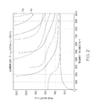
- FIG. 2 is a graph depicting exemplary dispersion curves for Aluminum 2024-T4;
- FIGS. 3-14 are images of a damage feature on a thin-wall structure, generated using conventional EUSR and the EUSR method described herein;
- FIG. 15 is a block diagram of a vehicle according to an embodiment.
- EUSR transmitter beamforming is based on the principle of constructive interference in a bundle of rays emitted from an array of sensor elements at a required steering angle, and destructive interferences anywhere else. This can be simply achieved by applying an appropriate time delay to each transmitted signal with regard to individual transmitter (sensor) position.
- the receiver beamforming is reciprocal to the transmitter beamforming
- original EUSR does not account for dispersion of Lamb waves (i.e. dependence of ultrasonic wave velocity on plate thickness/pulse frequency product). The dispersion results in degradation of spatial resolution of resulting EUSR image, which decreases accuracy of defect localization and sizing.
- FIG. 1 illustrates a system 10 for testing a thin-wall structure for damage according to one embodiment of the present invention.
- the system includes a thin-wall (or plate-like) structure 12 and a control system 14 .
- the thin-wall structure 12 is a square aluminum plate with a side length 16 of approximately 1000 mm and a thickness (not shown) of approximately 1 mm.
- the thin-wall structure 12 includes an array of ultrasonic transducers 18 (i.e., actuators/sensors) and a simulated damage feature 20 mounted thereto.
- Adjacent ultrasonic transducers 18 are separated by a distance 26 of approximately 5 mm.
- the ultrasonic transducers 18 may be piezoelectric transducers, as is commonly understood.
- the ultrasonic transducers are Noliac CMAP06 Ceramic Multilayer Actuator Plates, having length of 3 mm, a width of 3 mm, and a thickness of 2 mm.
- the damage feature 20 is in the form of a steel washer fixed on the surface of the thin-wall structure by means of double-sided tape (allowing the defect to be moved between experiments).
- the damage feature 20 is positioned a distance 28 away from the transducers 18 and/or the first axis 22 of the thin-wall structure 12 .
- the steel washer has an outer diameter of 16 mm, an inner diameter of 6 mm, and a thickness of 1.5 mm (not shown).
- the control system 14 includes control computer 30 , a waveform generator 32 , an amplifier 34 , and a receiver 36 , among other components.
- One or more of the components of the control system 14 includes a processor, which may be any one of numerous known general-purpose microprocessors or an application specific processor that operates in response to program instructions.
- the processor may include on-board random access memory (RAM) and on-board read only memory (ROM) that have program instructions stored thereon for carrying out the processes described herein.
- RAM random access memory
- ROM read only memory
- an Agilent 33220A 20 MHz Function/Arbitrary Waveform Generator, a Krohn-Hite KH 7500 Wideband Power Amplifier, and an Olympus 5800PR Computer controlled ultrasonic pulser/receiver were used.
- ultrasonic waves were created within the thin-wall structure 12 with an excitation pulse including six cycles of sine pulse bursts, weighted by a Gaussian window, applied to the transducers 18 .
- the burst period was set to 15 ms to assure that all reverberation was dismissed before the next burst was transmitted.
- the main frequency of the excitation pulse was tuned to 210 kHz to generate dominant A 0 mode.
- the signal sampling frequency was 10 MHz.
- EUSR was then used (i.e., by the control computer 30 ) to process the signals (i.e., echoes) detected by the transducers 18 .
- EUSR beamforming was performed in the frequency domain.
- the EUSR method assumes that data from an N-element sensor array is collected in a “round-robin” fashion using one sensor element at a time as a transmitter and the remaining sensor elements as receivers (either including or excluding the transmitting element). Then, with a total of N ⁇ N (or N ⁇ N ⁇ 1) data signals, EUSR implements beamforming as a signal post-processing operation.
- EUSR transmitter beamforming is based on the principle of constructive interference in the bundle of rays emitted by an array of sensor elements at a required angle ⁇ and destructive interferences anywhere else. This can be achieved by applying an appropriate time delay to each transmitted signal with regard to individual transmitter position.
- S-EUSR simple EUSR
- the so-called simple EUSR (S-EUSR) algorithm uses the parallel ray approximation to simplify the beamforming calculation. With the origin of the coordinate system located in the phase center of the linear sensor array, the delay for individual transmitters can be calculated using Equation (1), as follows:
- ⁇ m ⁇ ( ⁇ , m ) m ⁇ D ⁇ ⁇ cos ⁇ ( ⁇ ) c , ( 1 )
- m represents the m -th sensor in the linear array
- D is the sensor spacing
- c is the ultrasonic velocity for the material of the thin-wall structure given by Lamb wave dispersion curve for particular Lamb wave mode as a function of the wave frequency—structure thickness product
- ⁇ corresponds to the expected beam steering angle.
- G-EUSR generic EUSR
- ⁇ right arrow over (r) ⁇ is the position vector of the target
- ⁇ right arrow over (r) ⁇ m ⁇ right arrow over (r) ⁇ right arrow over (s) ⁇ m
- ⁇ right arrow over (s) ⁇ m is the position vector of the m -th sensor
- c is the ultrasonic velocity
- the receiver beamforming is reciprocal to the transmitter beamforming.
- the signals received at all of the sensors may be synchronized by delaying them by ⁇ m (i.e., Equation 1 for S-EUSR or Equation 2 for G-EUSR).
- the time delay for beamforming varies with ultrasonic wave frequency.
- the dependence of the wave velocity on the wave frequency is given by the Lamb wave dispersion curve for the particular wave propagation material and the particular Lamb wave mode.
- Exemplary dispersion curves for Aluminum 2024-T4 are depicted in FIG. 2 , with the symmetric modes being shown with dashed lines 38 and asymmetric modes being shown with solid lines 40 .
- EUSR is performed in the time domain. As such, it does not account for the dispersion of Lamb waves. That is, conventional EUSR does not account for the dependence of ultrasonic wave velocity on the plate thickness/pulse frequency product. This dispersion results in a spatial resolution degradation of the resulting EUSR image, which decreases the accuracy (both location and size) of damage detection.
- the delay-and-sum EUSR beamforming is conducted in the frequency domain using, for example, the Fourier transform.
- This allows the dispersion curve for a particular Lamb wave mode to be implemented into the EUSR calculation.
- spatial resolution in the direction perpendicular to the propagation of the steered beam is improved.
- the dispersion compensation is not performed prior to the EUSR processing. Rather, it is an integral part of the actual EUSR processing. Any presently known dispersion compensation/removal approach may be applied to the output of the approach disclosed herein, i.e. to the individual Lamb EUSR steered beams, to achieve improvement in both directions of the spatial resolution (parallel and perpendicular to the direction of propagation of the EUSR processed ultrasonic beam).
- A-scan amplitude modulation scan
- Equation (1) x mn (t) is the signal transmitted by m -th sensor and registered by n -th sensor
- N is the number of sensors in the sensor array
- ⁇ m and ⁇ n are delays for transmitter and receiver beamforming calculated using Equations (1) and (2), depending on whether near-field or far-field beamforming is applied.
- Equation (3) may be rewritten in frequency domain as
- Equation (4) Equation (4)
- Equation (5) represents an EUSR algorithm, or method, performed in the frequency domain, in accordance with one aspect of the present invention, which is used in the system 10 shown in FIG. 1 .
- FIGS. 3-14 illustrate the results of various EUSR processing schemes, including the EUSR method described herein. More specifically, FIGS. 3-14 are comparisons of image results for simple EUSR and generic EUSR approaches, both with and without dispersion being accounted for (i.e., in the frequency domain), for the system shown in FIG. 1 .
- the results depicted in FIGS. 3-14 were calculated using experimental data for simulated defect represented by a steel washer (similar to that described above) fixed on the surface of the thin-wall structure by means of double-sided sticking tape located on the sensor array axis at various distances from the array.
- the washer has an outer diameter of 16 mm, an inner diameter of 6 mm, and a thickness of 1.5 mm.
- As an excitation pulse a 6-count Gaussian windowed sine burst, centered at 210 kHz was used.
- the recorded waveforms were pre-processed, including windowing by a Hanning window, to eliminate the impact of transients at the beginning of the signal records. Wavelet filtration was also provided to remove zero drift and to eliminate frequency leakage.
- the defect was located 150 mm, 250 mm, and 350 mm from the first bisecting axis 22 ( FIG. 1 ) at 90° (i.e., on the second bisecting axis 24 ).
- S-EUSR simple EUSR
- G-EUSR generic EUSR
- Table I summarizes the lateral and axial spatial resolution measured as Full-Width-at-Half-Maximum (FWHM) of a defect response, the estimated image signal/noise ratio, and the time required for processing for the various EUSR approaches.
- FWHM Full-Width-at-Half-Maximum
- LS-EUSR and LG-EUSR beam steering approaches appear to nearly double spatial resolution in the direction perpendicular to beam propagation (i.e., lateral) over the S-EUSR or G-EUSR approaches.
- the ratio of the lateral spatial resolution improvement varies from case to case.
- a hybrid algorithm would include: calculation of EUSR A-scans using either simple or generic Lamb EUSR, and application of the dispersion compensation/removal algorithm on individual EUSR steered A-scans. Using such a hybrid algorithm could result in spatial resolution improvements in both directions—parallel and perpendicular to the direction of propagation of the steered ultrasonic beam.
- FIG. 15 schematically illustrates a vehicle 100 , such as an aircraft, in which the method and system described above may be implemented, according to one embodiment of the present invention.
- vehicle 100 may be, in one embodiment, any one of a number of different types of aircraft such as, for example, a private propeller or jet engine driven airplane, a commercial jet liner, or a helicopter.
- a private propeller or jet engine driven airplane such as, for example, a private propeller or jet engine driven airplane, a commercial jet liner, or a helicopter.
- helicopter a helicopter
- other embodiments may utilize the system described above on vehicles other than aircraft, such as watercraft and land vehicles.
- the aircraft 100 includes a frame (and/or hull) 110 , a flight deck 112 (or cockpit) and an avionics/flight system 114 .
- the flight deck 112 and the avionics/flight system 114 is connected to, or held within, the frame 110 .
- the frame 110 may be made of a metal, such as steel, aluminum, titanium, or a combination thereof.
- the sensor assembly i.e., ultrasonic transducers 18
- FIG. 1 may be coupled to the frame 110 of the vehicle and used in the manner described above to detect features (e.g., damage features) within the frame 110 .
- the flight deck 112 includes a user interface 116 , display devices 118 and 120 (e.g., a display screen for a flight management system (FMS) and a primary flight display (PFD)), a communications radio 122 , a navigational radio 124 , and an audio device 126 .
- the user interface 116 is configured to receive manual input from a user 128 (e.g., through a cursor control device 130 and a keyboard 132 ) and, in response to the user input, supply command signals to the avionics/flight system 114 .
- the avionics/flight system 114 includes a navigation and control system (or subsystem) 134 , an environmental control system (ECS) 136 , a cabin pressurization control system (CPCS) 138 , an auxiliary power unit (APU) control system 140 , an anti-skid brake-by-wire system 142 , a nose wheel steering system 144 , a landing gear control system 146 , an engine thrust reverse control system 148 , various other engine control systems 150 , a plurality of sensors 152 , one or more terrain databases 154 , one or more navigation databases 156 , and a processor 158 .
- the various components of the avionics/flight system 114 are in operable communication via sensor inputs (e.g., analog sensor inputs) 160 (or a data or avionics bus).
- the navigation and control system 134 may include a flight management system (FMS), an inertial navigation system (INS), an autopilot or automated guidance system, multiple flight control surfaces (e.g., ailerons, elevators, and a rudder), an Air Data Computer (ADC), an altimeter, an Air Data System (ADS), a Global Positioning System (GPS) module, an automatic direction finder (ADF), a compass, at least one engine, and gear (i.e., landing gear).
- FMS flight management system
- INS inertial navigation system
- ADC Air Data Computer
- ADS Air Data System
- GPS Global Positioning System
- ADF automatic direction finder
- compass at least one engine, and gear (i.e., landing gear).
- the processor (or processing system) 158 may be any one of numerous known general-purpose microprocessors or an application specific processor that operates in response to program instructions.
- the processor 158 includes on-board random access memory (RAM) and on-board read only memory (ROM).
- the program instructions that control the processor 158 may be stored in either or both the RAM and the ROM (or another computer-readable medium) and may include instructions for carrying out the processes described herein.
- the operating system software may be stored in the ROM, whereas various operating mode software routines and various operational parameters may be stored in the RAM. It will be appreciated that this is merely exemplary of one scheme for storing operating system software and software routines, and that various other storage schemes may be implemented.
- the processor may be implemented using various other circuits, not just a programmable processor. For example, digital logic circuits and analog signal processing circuits could also be used.
Landscapes
- Physics & Mathematics (AREA)
- Health & Medical Sciences (AREA)
- Life Sciences & Earth Sciences (AREA)
- Chemical & Material Sciences (AREA)
- Analytical Chemistry (AREA)
- Biochemistry (AREA)
- General Health & Medical Sciences (AREA)
- General Physics & Mathematics (AREA)
- Immunology (AREA)
- Pathology (AREA)
- Acoustics & Sound (AREA)
- Investigating Or Analyzing Materials By The Use Of Ultrasonic Waves (AREA)
Priority Applications (2)
| Application Number | Priority Date | Filing Date | Title |
|---|---|---|---|
| US12/786,220 US8429974B2 (en) | 2009-09-08 | 2010-05-24 | Lamb wave dispersion compensation for EUSR approach to ultrasonic beam steering |
| EP10173337.6A EP2293058B1 (de) | 2009-09-08 | 2010-08-18 | Lambwellen-Dispersionskompensation für das EUSR (Embedded Ultrasonic Strucure Radar)-Verfahren zur Ultraschallstrahllenkung |
Applications Claiming Priority (2)
| Application Number | Priority Date | Filing Date | Title |
|---|---|---|---|
| US24053009P | 2009-09-08 | 2009-09-08 | |
| US12/786,220 US8429974B2 (en) | 2009-09-08 | 2010-05-24 | Lamb wave dispersion compensation for EUSR approach to ultrasonic beam steering |
Publications (2)
| Publication Number | Publication Date |
|---|---|
| US20110058453A1 US20110058453A1 (en) | 2011-03-10 |
| US8429974B2 true US8429974B2 (en) | 2013-04-30 |
Family
ID=43066841
Family Applications (1)
| Application Number | Title | Priority Date | Filing Date |
|---|---|---|---|
| US12/786,220 Expired - Fee Related US8429974B2 (en) | 2009-09-08 | 2010-05-24 | Lamb wave dispersion compensation for EUSR approach to ultrasonic beam steering |
Country Status (2)
| Country | Link |
|---|---|
| US (1) | US8429974B2 (de) |
| EP (1) | EP2293058B1 (de) |
Cited By (2)
| Publication number | Priority date | Publication date | Assignee | Title |
|---|---|---|---|---|
| CN103808810A (zh) * | 2014-03-14 | 2014-05-21 | 哈尔滨工业大学 | 一种基于小波时频图和群速度曲线的钢轨裂纹声发射特征提取方法 |
| CN109856252A (zh) * | 2019-02-01 | 2019-06-07 | 南京信息工程大学 | 一种基于频散补偿与盲分离的多模式兰姆波分离方法 |
Families Citing this family (17)
| Publication number | Priority date | Publication date | Assignee | Title |
|---|---|---|---|---|
| CN102565201B (zh) * | 2011-10-25 | 2013-09-25 | 中国人民解放军理工大学 | 一种基于测量波数曲线的Lamb波频散补偿方法 |
| CN103278303B (zh) * | 2013-05-22 | 2015-11-04 | 株洲南车时代电气股份有限公司 | 一种轨道交通设备冲击试验波形补偿方法 |
| CN103344709B (zh) * | 2013-06-06 | 2015-09-09 | 南京航空航天大学 | 基于线性映射频散补偿的压电超声相控阵多损伤成像方法 |
| CN104391039B (zh) * | 2014-11-15 | 2017-04-12 | 中国特种设备检测研究院 | 基于动态小波指纹技术的储罐底板腐蚀非接触式超声检测方法 |
| CN105929029B (zh) * | 2016-04-18 | 2019-03-26 | 南京航空航天大学 | 一种用于sh导波无损检测技术中噪声处理方法 |
| CN105717198A (zh) * | 2016-05-12 | 2016-06-29 | 南京航空航天大学 | 一种面向结构冲击定位的单频-重估计music方法 |
| CN108896659B (zh) * | 2017-06-11 | 2021-09-14 | 嘉兴博传科技有限公司 | 一种扩大结构健康监测范围的方法及系统 |
| US11169118B2 (en) * | 2017-06-11 | 2021-11-09 | Broadsens Corp. | Method for extending detection range of a structural health monitoring system |
| CN107479499B (zh) * | 2017-09-29 | 2019-07-19 | 西北工业大学 | 薄壁件切削界面加工误差补偿建模与补偿系数学习控制方法 |
| CN107807176B (zh) * | 2017-10-12 | 2019-08-23 | 南京航空航天大学 | 一种频散Lamb波信号分辨率增强方法 |
| CN107807175B (zh) * | 2017-10-12 | 2019-04-23 | 南京航空航天大学 | 一种改进的频散超声导波信号域变换方法 |
| CN109632963B (zh) * | 2019-01-11 | 2020-10-20 | 南京航空航天大学 | 一种基于时不变特征信号构建的结构损伤四维成像方法 |
| CN110260827B (zh) * | 2019-06-18 | 2020-08-21 | 西安交通大学 | 基于大频厚积导波频散补偿的固定路桩长度估计方法 |
| CN110376282B (zh) * | 2019-07-15 | 2021-06-08 | 北京航空航天大学 | 一种基于椭圆概率与贝叶斯估计的Lamb波损伤定位法 |
| CN115616075A (zh) * | 2021-07-13 | 2023-01-17 | 中国石油天然气集团有限公司 | 基于超声兰姆波的储罐底板检测系统及方法 |
| CN113686959B (zh) * | 2021-09-15 | 2022-10-18 | 中国科学院声学研究所 | 一种基于超声兰姆波缺陷检测的成像方法及装置 |
| CN115753998B (zh) * | 2022-12-07 | 2024-08-27 | 大连理工大学 | 用于服役环境下飞行器复合材料结构损伤的监测方法及监测系统 |
Citations (20)
| Publication number | Priority date | Publication date | Assignee | Title |
|---|---|---|---|---|
| US3674998A (en) | 1970-03-04 | 1972-07-04 | Varian Associates | Method and apparatus for automatic phase control in a fourier analyzed readout of impulse resonance data |
| US4106327A (en) | 1977-11-22 | 1978-08-15 | The United States Of America As Represented By The United States Department Of Energy | Anisotropic determination and correction for ultrasonic flaw detection by spectral analysis |
| US4274288A (en) | 1979-07-23 | 1981-06-23 | Rockwell International Corporation | Method for measuring the depth of surface flaws |
| US4372163A (en) | 1981-02-03 | 1983-02-08 | Rockwell International Corporation | Acoustic measurement of near surface property gradients |
| US4755953A (en) | 1985-12-31 | 1988-07-05 | The Boeing Company | Ultrasonic testing apparatus |
| US5546811A (en) | 1995-01-24 | 1996-08-20 | Massachusetts Instittue Of Technology | Optical measurements of stress in thin film materials |
| US5672830A (en) | 1994-10-04 | 1997-09-30 | Massachusetts Institute Of Technology | Measuring anisotropic mechanical properties of thin films |
| US5734588A (en) | 1995-01-17 | 1998-03-31 | Electric Power Research Institute Inc. | Bore probe for tube inspection with guided waves and method therefor |
| US5956143A (en) | 1994-09-19 | 1999-09-21 | Textron Systems Corporation | Laser ultrasonics-based material analysis system and method utilizing lamb modes |
| US5992234A (en) | 1995-08-23 | 1999-11-30 | Quasar International | Detection of defects using resonant ultrasound spectroscopy at predicted high order modes |
| US6006163A (en) | 1997-09-15 | 1999-12-21 | Mcdonnell Douglas Corporation | Active damage interrogation method for structural health monitoring |
| US6182510B1 (en) | 1997-04-30 | 2001-02-06 | Sensys Instruments Corporation | Apparatus and method for characterizing semiconductor wafers during processing |
| US6393384B1 (en) | 1998-04-10 | 2002-05-21 | Textron Systems Corporation | Apparatus and method for remote ultrasonic determination of thin material properties using signal correlation |
| US6581014B2 (en) | 2000-07-20 | 2003-06-17 | Southwest Research Institute | Apparatus and method for analysis of guided ultrasonic waves |
| US20050228597A1 (en) | 2002-06-14 | 2005-10-13 | Victor Giurgiutiu | Structural health monitoring system utilizing guided lamb waves embedded ultrasonic structural radar |
| US20080288184A1 (en) | 2004-08-05 | 2008-11-20 | University Of South Carolina | Automatic Signal Collection and Analysis for Piezoelectric Wafer Active Sensor |
| US20080289423A1 (en) | 2007-05-22 | 2008-11-27 | Honeywell International, Inc. | Automated defect detection of corrosion or cracks using saft processed lamb wave images |
| US20090048789A1 (en) * | 2007-04-13 | 2009-02-19 | University Of South Carolina | Optimized Embedded Ultrasonics Structural Radar System With Piezoelectric Wafer Active Sensor Phased Arrays For In-Situ Wide-Area Damage Detection |
| US20090067286A1 (en) * | 2007-09-12 | 2009-03-12 | Schlumberger Technology Corporation | Dispersion extraction for acoustic data using time frequency analysis |
| US20090150094A1 (en) | 2007-11-14 | 2009-06-11 | Fbs, Inc. | Guided waves for nondestructive testing of pipes |
-
2010
- 2010-05-24 US US12/786,220 patent/US8429974B2/en not_active Expired - Fee Related
- 2010-08-18 EP EP10173337.6A patent/EP2293058B1/de not_active Not-in-force
Patent Citations (21)
| Publication number | Priority date | Publication date | Assignee | Title |
|---|---|---|---|---|
| US3674998A (en) | 1970-03-04 | 1972-07-04 | Varian Associates | Method and apparatus for automatic phase control in a fourier analyzed readout of impulse resonance data |
| US4106327A (en) | 1977-11-22 | 1978-08-15 | The United States Of America As Represented By The United States Department Of Energy | Anisotropic determination and correction for ultrasonic flaw detection by spectral analysis |
| US4274288A (en) | 1979-07-23 | 1981-06-23 | Rockwell International Corporation | Method for measuring the depth of surface flaws |
| US4372163A (en) | 1981-02-03 | 1983-02-08 | Rockwell International Corporation | Acoustic measurement of near surface property gradients |
| US4755953A (en) | 1985-12-31 | 1988-07-05 | The Boeing Company | Ultrasonic testing apparatus |
| US5956143A (en) | 1994-09-19 | 1999-09-21 | Textron Systems Corporation | Laser ultrasonics-based material analysis system and method utilizing lamb modes |
| US5672830A (en) | 1994-10-04 | 1997-09-30 | Massachusetts Institute Of Technology | Measuring anisotropic mechanical properties of thin films |
| US5734588A (en) | 1995-01-17 | 1998-03-31 | Electric Power Research Institute Inc. | Bore probe for tube inspection with guided waves and method therefor |
| US5546811A (en) | 1995-01-24 | 1996-08-20 | Massachusetts Instittue Of Technology | Optical measurements of stress in thin film materials |
| US5992234A (en) | 1995-08-23 | 1999-11-30 | Quasar International | Detection of defects using resonant ultrasound spectroscopy at predicted high order modes |
| US6182510B1 (en) | 1997-04-30 | 2001-02-06 | Sensys Instruments Corporation | Apparatus and method for characterizing semiconductor wafers during processing |
| US6006163A (en) | 1997-09-15 | 1999-12-21 | Mcdonnell Douglas Corporation | Active damage interrogation method for structural health monitoring |
| US6393384B1 (en) | 1998-04-10 | 2002-05-21 | Textron Systems Corporation | Apparatus and method for remote ultrasonic determination of thin material properties using signal correlation |
| US6581014B2 (en) | 2000-07-20 | 2003-06-17 | Southwest Research Institute | Apparatus and method for analysis of guided ultrasonic waves |
| US20050228597A1 (en) | 2002-06-14 | 2005-10-13 | Victor Giurgiutiu | Structural health monitoring system utilizing guided lamb waves embedded ultrasonic structural radar |
| US6996480B2 (en) | 2002-06-14 | 2006-02-07 | University Of South Carolina | Structural health monitoring system utilizing guided lamb waves embedded ultrasonic structural radar |
| US20080288184A1 (en) | 2004-08-05 | 2008-11-20 | University Of South Carolina | Automatic Signal Collection and Analysis for Piezoelectric Wafer Active Sensor |
| US20090048789A1 (en) * | 2007-04-13 | 2009-02-19 | University Of South Carolina | Optimized Embedded Ultrasonics Structural Radar System With Piezoelectric Wafer Active Sensor Phased Arrays For In-Situ Wide-Area Damage Detection |
| US20080289423A1 (en) | 2007-05-22 | 2008-11-27 | Honeywell International, Inc. | Automated defect detection of corrosion or cracks using saft processed lamb wave images |
| US20090067286A1 (en) * | 2007-09-12 | 2009-03-12 | Schlumberger Technology Corporation | Dispersion extraction for acoustic data using time frequency analysis |
| US20090150094A1 (en) | 2007-11-14 | 2009-06-11 | Fbs, Inc. | Guided waves for nondestructive testing of pipes |
Non-Patent Citations (5)
| Title |
|---|
| EP Search Report, EP 10173337.6-2204 dated Dec. 7, 2010. |
| Giurgiutu V.; Chapter 7: Embedded Ultrasonic NDE With Piezoelectric Wafer Active Sensors; Advanced Ultrasonic Methods for Material and Structure Inspection, Wiley, GB, Jan. 1, 2007, pp. 237-272. |
| Lingyu Yu et al.; Design, Implementation, and Comparison of Guided Wave Phased Arrays Using Embedded Piezoelectric Wafer Active Sensors for Structural Health Monitoring; Smart Structures and Materials 2006: Smart Structures and Integrated Systems, Feb. 27, 2006, San Diego, CA, vol. 6173, 2006, pp. 61731M-1-61731M-12. |
| Ostachowicz W., et al.; Damage Localisation in Plate-Like Structures Based on PZT Sensors; Mechanical Systems and Signal Processing, London, GB, vol. 23, No. 6, Aug. 1, 2009, pp. 1805-1829. |
| Victor Giurgiutiu, Lingyu Yu, and 2-Lt. Dustin Thomas, "Embedded Ultrasonic Structural Rada wtih Piezoelectric Wafer Active Sensors for Damage Detection in Cylindrical Shell Structures", Apr. 2004, American Institute of Aeronautics and Astronauts, paper # AiAA-2004-1983, pp. 114. * |
Cited By (3)
| Publication number | Priority date | Publication date | Assignee | Title |
|---|---|---|---|---|
| CN103808810A (zh) * | 2014-03-14 | 2014-05-21 | 哈尔滨工业大学 | 一种基于小波时频图和群速度曲线的钢轨裂纹声发射特征提取方法 |
| CN109856252A (zh) * | 2019-02-01 | 2019-06-07 | 南京信息工程大学 | 一种基于频散补偿与盲分离的多模式兰姆波分离方法 |
| CN109856252B (zh) * | 2019-02-01 | 2021-03-16 | 南京信息工程大学 | 一种基于频散补偿与盲分离的多模式兰姆波分离方法 |
Also Published As
| Publication number | Publication date |
|---|---|
| EP2293058A1 (de) | 2011-03-09 |
| US20110058453A1 (en) | 2011-03-10 |
| EP2293058B1 (de) | 2014-06-11 |
Similar Documents
| Publication | Publication Date | Title |
|---|---|---|
| EP2293058B1 (de) | Lambwellen-Dispersionskompensation für das EUSR (Embedded Ultrasonic Strucure Radar)-Verfahren zur Ultraschallstrahllenkung | |
| Kudela et al. | Structural Health Monitoring system based on a concept of Lamb wave focusing by the piezoelectric array | |
| Feng et al. | Interaction of Lamb waves with the edges of a delamination in CFRP composites and a reference-free localization method for delamination | |
| Hua et al. | Time-frequency damage index of Broadband Lamb wave for corrosion inspection | |
| US20130327148A1 (en) | Systems and methods for damage detection in plate-like structures using guided wave phased arrays | |
| US9638671B2 (en) | Systems and methods for damage detection in structures using guided wave phased arrays | |
| US9910016B2 (en) | Piezoelectric shear rings for omnidirectional shear horizontal guided wave excitation and sensing | |
| EP2472254B1 (de) | Verfahren zur zerstörungsfreien ultraschallprüfung, inbesondere für verbundwerkstoffstrukturen für aeronautische anwendungen | |
| US10126273B2 (en) | Inspection of structures | |
| Michaels | Ultrasonic wavefield imaging: Research tool or emerging NDE method? | |
| US8015877B2 (en) | Imaging an anomaly using backscattered waves | |
| Mirahmadi et al. | Application of signal processing techniques to ultrasonic testing of plates by S0 Lamb wave mode | |
| Hua et al. | Sparse reconstruction imaging of damage for Lamb wave simultaneous excitation system in composite laminates | |
| KR20160139915A (ko) | 전영역 펄스-에코 레이저 초음파전파영상화 장치 및 방법 | |
| CN113777166A (zh) | 一种基于超声平面波成像和时间反转算子相结合的高分辨缺陷无损检测方法 | |
| Bahador et al. | Three-stage Lamb-wave-based damage localization algorithm in plate-like structures for structural health monitoring applications | |
| CN110199194B (zh) | 使用超声波来检测部件的多元件方法及装置 | |
| CN104374830A (zh) | 一种基于压电阵列的近场相控阵结构健康监测方法 | |
| Michaels et al. | Damage localization in inhomogeneous plates using a sparse array of ultrasonic transducers | |
| Fredianelli et al. | Acoustic source localization in ports with different beamforming algorithms | |
| EP3882639B1 (de) | Akustisches luftdatensystem mit radial gepaarten empfängern | |
| Kirchhof et al. | Sparse signal recovery for ultrasonic detection and reconstruction of shadowed flaws | |
| Zhang et al. | A time delay-weighted total focusing method for lamb wave-based damage imaging in three-element dense arrays | |
| CN106018560A (zh) | 无人船船体中裂缝扩展的超声探测器 | |
| Rocha et al. | Structural health monitoring system using piezoelectric networks with tuned lamb waves |
Legal Events
| Date | Code | Title | Description |
|---|---|---|---|
| AS | Assignment |
Owner name: HONEYWELL INTERNATIONAL INC., NEW JERSEY Free format text: ASSIGNMENT OF ASSIGNORS INTEREST;ASSIGNORS:HEDL, RADEK;PARTHASARATHY, GIRIJA;SIGNING DATES FROM 20100523 TO 20100524;REEL/FRAME:024432/0086 |
|
| STCF | Information on status: patent grant |
Free format text: PATENTED CASE |
|
| FPAY | Fee payment |
Year of fee payment: 4 |
|
| FEPP | Fee payment procedure |
Free format text: MAINTENANCE FEE REMINDER MAILED (ORIGINAL EVENT CODE: REM.); ENTITY STATUS OF PATENT OWNER: LARGE ENTITY |
|
| LAPS | Lapse for failure to pay maintenance fees |
Free format text: PATENT EXPIRED FOR FAILURE TO PAY MAINTENANCE FEES (ORIGINAL EVENT CODE: EXP.); ENTITY STATUS OF PATENT OWNER: LARGE ENTITY |
|
| STCH | Information on status: patent discontinuation |
Free format text: PATENT EXPIRED DUE TO NONPAYMENT OF MAINTENANCE FEES UNDER 37 CFR 1.362 |
|
| FP | Lapsed due to failure to pay maintenance fee |
Effective date: 20210430 |