US8429818B2 - Rod holder for the assembly of heat exchangers - Google Patents
Rod holder for the assembly of heat exchangers Download PDFInfo
- Publication number
- US8429818B2 US8429818B2 US12/501,745 US50174509A US8429818B2 US 8429818 B2 US8429818 B2 US 8429818B2 US 50174509 A US50174509 A US 50174509A US 8429818 B2 US8429818 B2 US 8429818B2
- Authority
- US
- United States
- Prior art keywords
- plate
- aperture
- recited
- displacement mechanism
- expansion rod
- Prior art date
- Legal status (The legal status is an assumption and is not a legal conclusion. Google has not performed a legal analysis and makes no representation as to the accuracy of the status listed.)
- Expired - Fee Related, expires
Links
Images


Classifications
-
- B—PERFORMING OPERATIONS; TRANSPORTING
- B21—MECHANICAL METAL-WORKING WITHOUT ESSENTIALLY REMOVING MATERIAL; PUNCHING METAL
- B21D—WORKING OR PROCESSING OF SHEET METAL OR METAL TUBES, RODS OR PROFILES WITHOUT ESSENTIALLY REMOVING MATERIAL; PUNCHING METAL
- B21D53/00—Making other particular articles
- B21D53/02—Making other particular articles heat exchangers or parts thereof, e.g. radiators, condensers fins, headers
- B21D53/08—Making other particular articles heat exchangers or parts thereof, e.g. radiators, condensers fins, headers of both metal tubes and sheet metal
- B21D53/085—Making other particular articles heat exchangers or parts thereof, e.g. radiators, condensers fins, headers of both metal tubes and sheet metal with fins places on zig-zag tubes or parallel tubes
-
- B—PERFORMING OPERATIONS; TRANSPORTING
- B21—MECHANICAL METAL-WORKING WITHOUT ESSENTIALLY REMOVING MATERIAL; PUNCHING METAL
- B21D—WORKING OR PROCESSING OF SHEET METAL OR METAL TUBES, RODS OR PROFILES WITHOUT ESSENTIALLY REMOVING MATERIAL; PUNCHING METAL
- B21D39/00—Application of procedures in order to connect objects or parts, e.g. coating with sheet metal otherwise than by plating; Tube expanders
- B21D39/06—Application of procedures in order to connect objects or parts, e.g. coating with sheet metal otherwise than by plating; Tube expanders of tubes in openings, e.g. rolling-in
-
- F—MECHANICAL ENGINEERING; LIGHTING; HEATING; WEAPONS; BLASTING
- F16—ENGINEERING ELEMENTS AND UNITS; GENERAL MEASURES FOR PRODUCING AND MAINTAINING EFFECTIVE FUNCTIONING OF MACHINES OR INSTALLATIONS; THERMAL INSULATION IN GENERAL
- F16B—DEVICES FOR FASTENING OR SECURING CONSTRUCTIONAL ELEMENTS OR MACHINE PARTS TOGETHER, e.g. NAILS, BOLTS, CIRCLIPS, CLAMPS, CLIPS OR WEDGES; JOINTS OR JOINTING
- F16B9/00—Connections of rods or tubular parts to flat surfaces at an angle
- F16B9/05—Connections of rods or tubular parts to flat surfaces at an angle by way of an intermediate member
- F16B9/056—Connections of rods or tubular parts to flat surfaces at an angle by way of an intermediate member the intermediate member extending through the flat surface; the rod or tubular part extending through the flat surface
-
- F—MECHANICAL ENGINEERING; LIGHTING; HEATING; WEAPONS; BLASTING
- F16—ENGINEERING ELEMENTS AND UNITS; GENERAL MEASURES FOR PRODUCING AND MAINTAINING EFFECTIVE FUNCTIONING OF MACHINES OR INSTALLATIONS; THERMAL INSULATION IN GENERAL
- F16B—DEVICES FOR FASTENING OR SECURING CONSTRUCTIONAL ELEMENTS OR MACHINE PARTS TOGETHER, e.g. NAILS, BOLTS, CIRCLIPS, CLAMPS, CLIPS OR WEDGES; JOINTS OR JOINTING
- F16B21/00—Means for preventing relative axial movement of a pin, spigot, shaft or the like and a member surrounding it; Stud-and-socket releasable fastenings
- F16B21/09—Releasable fastening devices with a stud engaging a keyhole slot
-
- F—MECHANICAL ENGINEERING; LIGHTING; HEATING; WEAPONS; BLASTING
- F16—ENGINEERING ELEMENTS AND UNITS; GENERAL MEASURES FOR PRODUCING AND MAINTAINING EFFECTIVE FUNCTIONING OF MACHINES OR INSTALLATIONS; THERMAL INSULATION IN GENERAL
- F16B—DEVICES FOR FASTENING OR SECURING CONSTRUCTIONAL ELEMENTS OR MACHINE PARTS TOGETHER, e.g. NAILS, BOLTS, CIRCLIPS, CLAMPS, CLIPS OR WEDGES; JOINTS OR JOINTING
- F16B21/00—Means for preventing relative axial movement of a pin, spigot, shaft or the like and a member surrounding it; Stud-and-socket releasable fastenings
- F16B21/10—Means for preventing relative axial movement of a pin, spigot, shaft or the like and a member surrounding it; Stud-and-socket releasable fastenings by separate parts
- F16B21/16—Means for preventing relative axial movement of a pin, spigot, shaft or the like and a member surrounding it; Stud-and-socket releasable fastenings by separate parts with grooves or notches in the pin or shaft
-
- Y—GENERAL TAGGING OF NEW TECHNOLOGICAL DEVELOPMENTS; GENERAL TAGGING OF CROSS-SECTIONAL TECHNOLOGIES SPANNING OVER SEVERAL SECTIONS OF THE IPC; TECHNICAL SUBJECTS COVERED BY FORMER USPC CROSS-REFERENCE ART COLLECTIONS [XRACs] AND DIGESTS
- Y10—TECHNICAL SUBJECTS COVERED BY FORMER USPC
- Y10T—TECHNICAL SUBJECTS COVERED BY FORMER US CLASSIFICATION
- Y10T29/00—Metal working
- Y10T29/49—Method of mechanical manufacture
- Y10T29/4935—Heat exchanger or boiler making
- Y10T29/49373—Tube joint and tube plate structure
- Y10T29/49375—Tube joint and tube plate structure including conduit expansion or inflation
-
- Y—GENERAL TAGGING OF NEW TECHNOLOGICAL DEVELOPMENTS; GENERAL TAGGING OF CROSS-SECTIONAL TECHNOLOGIES SPANNING OVER SEVERAL SECTIONS OF THE IPC; TECHNICAL SUBJECTS COVERED BY FORMER USPC CROSS-REFERENCE ART COLLECTIONS [XRACs] AND DIGESTS
- Y10—TECHNICAL SUBJECTS COVERED BY FORMER USPC
- Y10T—TECHNICAL SUBJECTS COVERED BY FORMER US CLASSIFICATION
- Y10T29/00—Metal working
- Y10T29/53—Means to assemble or disassemble
- Y10T29/53113—Heat exchanger
- Y10T29/53122—Heat exchanger including deforming means
Definitions
- This application is directed, in general, to a tube expander machine and, more specifically, to a device for locking and releasing tube expander rods for a heat exchanger.
- one method in common use is to assemble fins on tubes with a loose fit and then expand the tubes to produce a tight fit with the fins and permanently lock the assembly together. This also provides good heat exchange contact between the tubes and the fins.
- expander machines provide a frame having an assembly fixture or nest at one end for holding the loosely assembled tubes and fins and a powered header or ram at the other end.
- Mounted on the powered ram is a plurality of expander rods aligned with the tubes in the fixture or nest.
- the ends of the rods are formed with expander ends, or bullets, sized to move along the tube as the ram advances and to expand the tube into tight fitting engagement with the openings in the fins.
- One common method of securing the expander rods to the powered header is to insert the rods into selected apertures in the header and rotate the rods 180°, the rods having a half-groove milled into one side of the rod near the upper, tapered end. Therefore, inserting or removing the rods to convert to a different heat exchanger pattern requires each rod to be twisted and removed or, inserted and twisted to secure it in the header. All of this repetitive motion of twisting is done by hand and often results in the repetitive stress injury (RSI) known as carpal tunnel syndrome and also requires additional manufacturing time and effort, thereby increasing manufacturing costs.
- RSI repetitive stress injury
- the expansion rod holder for the assembly of fin and tube heat exchangers.
- the expansion rod holder comprises a first plate having a first aperture therethrough and a ring located in the first aperture and that has a second aperture therethrough.
- the first and second apertures are configured to receive a tapered end of an expansion rod having an annular groove proximate the tapered end.
- a biasing member is located in the first aperture between the ring and a wall of the first aperture. The biasing member is configured to bias the ring in a first direction toward an opposite wall of the first aperture and into the annular groove.
- a method of manufacturing the expansion rod holder is also disclosed, as well as a tube expander system used to manufacture heat exchangers.
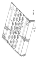
- FIG. 1 illustrates one embodiment of an expansion rod holder for the assembly of fin and tube heat exchangers as discussed herein;
- FIG. 2 illustrates one embodiment of the first plate having the plurality of first apertures therethrough
- FIG. 3A illustrates one embodiment of a tapered end of an expansion rod configured to cooperate with the expansion rod holder of FIG. 1 ;
- FIG. 3B illustrates one embodiment of the ring of the expansion rod holder of FIG. 1 ;
- FIG. 4 illustrates a portion of the first and second plates with one expansion rod locked in place
- FIG. 5A illustrates one embodiment of a mechanical tube expander employing a rod holder for manufacturing heat exchangers constructed according to the principles of the present invention
- FIG. 5B is an enlarged view of a portion of the mechanical tube expander with the components oriented in a first position.
- FIG. 1 illustrates one embodiment of an expansion rod holder 100 for the assembly of fin and tube heat exchangers, as discussed herein.
- the expansion rod holder 100 comprises a first plate 110 , a second plate 120 , and a displacement mechanism 130 .
- the first plate 110 comprises a plurality of apertures 111 therethrough and first and second tongues 112 , 113 .
- the plurality of apertures 111 may be arranged in a pattern replicating a general cross section for a family of heat exchangers (not shown). For example, the illustrated plurality of apertures 111 arranged in four offset rows of 36 apertures alternating with rows of 37 apertures, i.e., 36 apertures, 37 apertures, 36 apertures, and 37 apertures.
- the exact number is not important, nor is the layout, so long as the pattern is large enough to accommodate the number of tubes to be expanded within a like number of fins ultimately to be formed into a heat exchanger.
- the first plate 110 shown comprises six partial plates 110 a - 110 f that are interlocked as in the pieces of a jigsaw puzzle. However, the first plate 110 need not be made from six or any other number of partial plates, but may be made in one piece.
- the illustrated embodiment is convenient to manufacture on tools of a modest size. The availability of larger manufacturing tools may enable the manufacture of the first plate 110 in one piece.
- the second plate 120 comprises a cavity 121 in the upper surface 122 in which the first plate 110 is located.
- the cavity 121 may be a rabbet having a length l r that is longer than the first plate length l fp .
- the second plate 120 may further comprise a plurality of mounting apertures 123 for mounting to a ram header (not shown) of a mechanical tube expander.
- the cavity 121 has a depth substantially equal to a thickness of the first plate 110 , such that the upper surface of the first and second plates 110 and 120 are substantially coplanar.
- the expansion rod holder 100 may include a displacement mechanism 130 that is operatively coupled to the first and second plates 110 and 120 .
- the displacement mechanism 130 is configured to provide a mechanical force to shift the first plate 110 with respect to the second plate 120 .
- the displacement mechanism 130 may comprise an actuator 131 , an attachment bracket 132 , first and second tongue brackets 133 , 134 and a connecting rod 135 .
- the displacement mechanism 130 is coupled to the second plate 120 at an edge 124 thereof with attachment bracket 132 .
- the displacement mechanism 130 is also coupled to the first plate 110 at the first and second tongues 112 , 113 with the first and second tongue brackets 133 , 134 .
- the connecting rod 135 couples the first and second tongue brackets 133 , 134 so as to precisely adjust the distance between the first and second tongues 112 , 113 so that the first plate 110 remains planar during sliding operation.
- the connecting rod 135 may be threaded as in a turnbuckle, i.e., left handed threads on one end and right handed threads on the other end, so that rotating the connecting rod 135 in one direction shortens the distance between the first and second tongues 112 , 113 and shifts the first plate 110 to the right with respect to the second plate 120 , and rotating the connecting rod 135 in the opposite direction lengthens the distance between the first and second tongues 112 , 113 to shift the first plate 110 in the opposite direction.
- the actuator 131 may be a hydraulic operated device that pulls or pushes the rod 135 in the desired direction.
- the actuator may simply be an appropriately levered handle that allows the plate 110 to be shifted in the appropriate direction when the handle is moved or biased in the appropriate direction. Examples of other embodiments of the displacement mechanism 130 are discussed below.
- FIG. 2 illustrates one embodiment of the first plate 110 having the plurality of first apertures 111 therethrough. Portions of the second plate 120 may be seen through the first apertures 111 as well as second plate apertures 230 through which ends of expansion rods 235 can be inserted.
- the first apertures 111 are elongated along the length of the first plate 110 to provide optimal spacing of adjacent rows of the first apertures 111 .
- a ring 210 Within each of the first apertures 111 is located a ring 210 and a biasing member 220 , as illustrated.
- the biasing member 220 is comprised of a resilient material that is capable of exerting a force when compressed.
- the biasing member 220 may be comprised of rubber or similar elastic material capable of exerting a force when compressed.
- the rings 210 and biasing members 220 are substantially co-planar with the first plate 110 .
- the upper surfaces of the rings 210 and biasing members 220 may be located below the upper surface of the first plate 110 .
- the rings 210 and biasing members 220 are of a thickness substantially equal to a thickness of the first plate 110 . However, in other embodiments, their thickness may be thinner than the first plate 110 .
- the rings 210 have central second apertures 215 therethrough.
- the central second apertures 215 have a diameter d a .
- the rings 210 may also have beveled sections 217 as part of the interior wall of the central second apertures 215 .
- the biasing members 220 are located in the first apertures 111 between one wall 211 of the first apertures 111 and the ring 210 associated therewith. As generally illustrated in FIG. 2 , the biasing members 220 are configured to bias the ring 210 in a first direction toward an opposite wall 212 of the first aperture 111 and an annular groove 315 (See FIG. 3A ) of the expansion rod 235 , as generally illustrated in FIG. 2 .
- FIG. 3A illustrates one embodiment of a tapered end 310 of the expansion rod 235 configured to cooperate with the expansion rod holder 100 of FIG. 1 .
- the expansion rod 235 has a diameter d r .
- the end 310 is tapered to simplify insertion into the expansion rod holder 100 .
- the expansion rod 235 has a region 313 of full rod diameter d r .
- Proximate the tapered end 310 at an end of region 313 is an annular groove 315 .
- the expansion rod 235 diameter d r is slightly smaller than the central second aperture diameter d a , thereby enabling the tapered end 310 to pass readily therethrough.
- the difference between the length of the cavity 121 and the length of the first plate 110 is substantially equal to a depth d g of the annular groove 315 .
- This dimensional relationship allows for precise movement of the first plate 110 with respect to the second plate 120 to allow the rods 235 to be cooperatively secured into place by the ring 210 cooperating with the biasing member 220 and removed from the plate 110 by using the displacement mechanism 130 ( FIG. 1 ).
- FIG. 3B illustrates an advantageous embodiment of the ring 210 .
- the ring 210 has a thickness and cross section that cooperates with the annular groove 315 to retain the expansion rod 235 in the expansion rod holder 100 ( FIG. 1 ).
- the ring 210 may also include a beveled section 217 , which helps to guide the insertion of the tapered end 310 into the respective apertures 111 and 215 of the plate 110 and the rings 210 .
- FIG. 4 illustrates a portion of the first and second plates 110 , 120 with one expansion rod 235 locked in place.
- the tapered end 310 and the region 313 of full rod diameter d r are seen extending above the first plate 110 .
- the expansion rod 235 is held in place by the ring 210 under the force exerted by the biasing member 220 .
- the tapered end 310 of the expansion rod 235 is inserted through the aperture 230 of the second plate 210 and then simultaneously through the ring aperture 215 and the first plate aperture 111 .
- the ring 210 slides toward the one wall 211 and is resisted by resilient biasing member 220 .
- the resilient biasing member 220 is an arcuate, resilient member comprising a rubber segment with suitable compression and resiliency characteristics.
- region 313 comes smoothly into contact with interior wall 215 and the expansion rod 235 is therefore centered in the second plate aperture 230 and the ring 210 . Further insertion of the expansion rod 235 results in the ring 210 sliding into the annular groove 315 , locking the expansion rod 235 in the expansion rod holder 100 . This insertion process is repeated for each expansion rod that is needed to form the fin and tube arrangement for the desired heat exchanger.
- the expansion rod arrangement no longer suits the fin and tube heat exchangers being produced, i.e., a new arrangement of expansion rods 235 is needed or rods need to be replaced for some other reason, the expansion rods 235 are released with the aid of the displacement mechanism 130 .
- the cavity length l r in the second plate 120 is longer than the first plate 110 length l fp . This difference in length allows the first plate 110 to move slightly in the cavity 121 along the second plate 120 .
- the second plate 120 in one embodiment, may be secured to a hydraulic head which will be described below that exerts the necessary force to cause the expansion rods 235 to pass through the tubes, expanding them into contact with the fins.
- the displacement mechanism 130 shifts the first plate 110 with respect to the second plate 120 in the cavity 121 to release the expansion rods 235 from the rings 210 in the first plate 110 .
- the displacement mechanism 130 is a hydraulically-operated displacement mechanism.
- a hydraulically-operated displacement mechanism is a displacement mechanism wherein hydraulic pressure is used to cause the relative motion between the first plate 110 and the second plate 120 .
- the expansion rods 235 are held by the rings 210
- the first plate 110 is shifted toward the left in FIG. 1 by the biasing members 220 .
- hydraulic pressure is applied to hydraulic actuator 131 , the hydraulic pressure causes first tongue bracket 133 , connecting rod 135 and second tongue bracket 134 to move in unison to the right in FIG.
- first and second tongue brackets 133 , 134 causes the first and second tongues 112 , 113 and the first plate 110 to displace to the right relative to the second plate 120 .
- the resilient biasing members 220 are compressed between the one wall 211 and the ring 210 , and the second aperture 215 aligns with the second plate aperture 230 , thereby allowing the expansion rods 235 to be withdrawn vertically from the expansion rod holder 100 .
- the rings 210 will shift to the left in the first apertures 111 as a result of the force applied by the biasing members 220 .
- the displacement mechanism 130 may be a mechanical displacement mechanism.
- a mechanical displacement mechanism uses one or more mechanical devices, e.g., a lever, screw or other simple mechanical means well known to those of skill in the art, to shift the first plate 110 in the cavity 121 .
- the displacement mechanism 130 may be an electrical displacement mechanism.
- An example of an electrical displacement mechanism would be an electromagnetic field applied to suitable material, i.e., steel, iron, ferromagnetic, etc., coupled to the first and second tongue brackets 133 , 134 to shift the first plate 110 in the cavity 121 .
- FIGS. 5A and 5B illustrate a mechanical tube expander 500 employing a rod holder for manufacturing heat exchangers constructed according to the principles of the present invention and an enlarged elevation view of a portion of the mechanical tube expander with the components oriented in a first position.
- the mechanical tube expander 500 comprises an upstanding frame 510 having a base plate 520 oriented adjacent the lower end 530 thereof having conventional structure 540 for holding on the base plate 520 an assembly of a plurality of fins F and like plurality of tubes T, the fins F being loosely stacked on the tubes T and supported by the aforesaid structure 540 .
- a ram drive cylinder 550 is mounted on the upstanding frame 510 adjacent the upper end 560 thereof.
- the ram drive cylinder 550 has an elongate ram 555 whose longitudinal axis extends vertically.
- the lower end of the ram 555 is secured to a pressure plate 570 which carries thereon a plurality of expander rods 580 secured in a rod holder 590 constructed according to the principles of the present invention.
- the expander rods 580 have parallel axes and each of the axes is aligned with an axis of a selected one of the tubes T.
- Each expander rod 580 has at a lower end thereof an enlarged tube-expanding tip 583 .
- the ram drive cylinder 550 When the ram drive cylinder 550 is activated, the ram 555 will reciprocally drive the pressure plate 570 .
- Any expander rods 580 connected to the rod holder 590 will also be reciprocally driven into the aligned tubes T so that the enlarged tube-expanding tip 583 will expand the tubes T so as to become fixedly engaged with the fins previously loosely stacked on the aforesaid tubes T.
- the enlarged tube-expanding tips 583 are also known in the art as expander bullets.
- the expander rods 580 extend through guide plates 573 and 575 .
- Vertical guide rods 579 are provided for guiding the vertical reciprocating movement of the pressure plate 570 and other reciprocal parts of the mechanical tube expander 500 .
- the rod holder features easy rod insertion and positive retention as well as convenient release of the rods when reconfiguration is required.
Landscapes
- Engineering & Computer Science (AREA)
- Mechanical Engineering (AREA)
- General Engineering & Computer Science (AREA)
- Heat-Exchange Devices With Radiators And Conduit Assemblies (AREA)
- Details Of Heat-Exchange And Heat-Transfer (AREA)
- Automatic Assembly (AREA)
Priority Applications (8)
| Application Number | Priority Date | Filing Date | Title |
|---|---|---|---|
| US12/501,745 US8429818B2 (en) | 2009-07-13 | 2009-07-13 | Rod holder for the assembly of heat exchangers |
| CA2708697A CA2708697C (en) | 2009-07-13 | 2010-06-28 | Rod holder for the assembly of heat exchangers |
| AU2010202812A AU2010202812B2 (en) | 2009-07-13 | 2010-07-02 | Rod holder for the assembly of heat exchangers |
| CL2010000727A CL2010000727A1 (es) | 2009-07-13 | 2010-07-07 | Soporte de varilla expansora para el armado de intercambiadores de calor de aleta y tubo, con una primera placa que posee una primera abertura pasante, un anillo ubicado en dicha primera abertura, presentando dicho anillo una segunda abertura pasante; un miembro de guia configurado para desviar dicho dicho anillo; metodo y sistema. |
| ARP100102493A AR078058A1 (es) | 2009-07-13 | 2010-07-08 | Soporte de varilla para el armado de intercambiadores de calor |
| MX2010007637A MX2010007637A (es) | 2009-07-13 | 2010-07-12 | Sujetador de varilla para el ensamble de intercambiadores de calor. |
| CN201010226971.XA CN101954431B (zh) | 2009-07-13 | 2010-07-12 | 用于换热器的组装的杆保持器 |
| EP10169416.4A EP2277643B1 (de) | 2009-07-13 | 2010-07-13 | Dornhalter für den Zusammenbau von Wärmetauschern |
Applications Claiming Priority (1)
| Application Number | Priority Date | Filing Date | Title |
|---|---|---|---|
| US12/501,745 US8429818B2 (en) | 2009-07-13 | 2009-07-13 | Rod holder for the assembly of heat exchangers |
Publications (2)
| Publication Number | Publication Date |
|---|---|
| US20110005067A1 US20110005067A1 (en) | 2011-01-13 |
| US8429818B2 true US8429818B2 (en) | 2013-04-30 |
Family
ID=43033503
Family Applications (1)
| Application Number | Title | Priority Date | Filing Date |
|---|---|---|---|
| US12/501,745 Expired - Fee Related US8429818B2 (en) | 2009-07-13 | 2009-07-13 | Rod holder for the assembly of heat exchangers |
Country Status (8)
| Country | Link |
|---|---|
| US (1) | US8429818B2 (de) |
| EP (1) | EP2277643B1 (de) |
| CN (1) | CN101954431B (de) |
| AR (1) | AR078058A1 (de) |
| AU (1) | AU2010202812B2 (de) |
| CA (1) | CA2708697C (de) |
| CL (1) | CL2010000727A1 (de) |
| MX (1) | MX2010007637A (de) |
Families Citing this family (14)
| Publication number | Priority date | Publication date | Assignee | Title |
|---|---|---|---|---|
| CN103934656B (zh) * | 2014-03-21 | 2016-05-04 | 珠海格力电器股份有限公司 | 多层换热器穿管装置及工装 |
| CN104368709B (zh) * | 2014-09-26 | 2016-03-16 | 奥美森智能装备股份有限公司 | 一种胀管机的扩口杯选择装置 |
| US9638357B1 (en) | 2015-06-24 | 2017-05-02 | Omax Corporation | Mechanical processing of high aspect ratio metallic tubing and related technology |
| CN107322286A (zh) * | 2017-08-11 | 2017-11-07 | 成都领专科技有限责任公司 | 用于冷凝器装配的辅助装置及冷凝器自动插管设备 |
| CN108246905A (zh) * | 2017-11-30 | 2018-07-06 | 珠海格力智能装备有限公司 | 门板压紧机构及具有其的胀管机 |
| CN108213233B (zh) * | 2017-11-30 | 2024-01-30 | 珠海格力智能装备有限公司 | 工作台机构及具有其的胀管机 |
| CN108246903B (zh) * | 2017-11-30 | 2024-03-08 | 珠海格力智能装备有限公司 | 胀管加工装置及具有其的胀管机 |
| EP4127527A1 (de) | 2020-03-24 | 2023-02-08 | Hypertherm, Inc. | Hochdruckdichtung für ein flüssigkeitsstrahlschneidsystem |
| WO2021202390A1 (en) | 2020-03-30 | 2021-10-07 | Hypertherm, Inc. | Cylinder for a liquid jet pump with multi-functional interfacing longitudinal ends |
| CN114776681B (zh) * | 2021-01-22 | 2024-03-22 | 宾科精密部件(中国)有限公司 | 铆接方法及铆接结构 |
| CN113059071B (zh) * | 2021-05-17 | 2022-10-28 | 珠海格力智能装备有限公司 | 选配机构及加工设备 |
| CN114054615B (zh) * | 2021-11-17 | 2025-11-11 | 奥美森智能装备股份有限公司 | 一种胀管机及其胀杆自动选择装置 |
| CN115647222B (zh) * | 2022-10-13 | 2025-12-16 | 中山市科力高自动化设备有限公司 | 胀管夹紧机构 |
| CN115805271A (zh) * | 2022-12-26 | 2023-03-17 | 奥美森智能装备股份有限公司 | 一种胀管机 |
Citations (11)
| Publication number | Priority date | Publication date | Assignee | Title |
|---|---|---|---|---|
| US3688533A (en) | 1970-10-19 | 1972-09-05 | Tridan Tool & Machine | Tube expansion apparatus |
| US4581817A (en) * | 1983-03-18 | 1986-04-15 | Haskel, Inc. | Drawbar swaging apparatus with segmented confinement structure |
| US4734972A (en) | 1986-01-15 | 1988-04-05 | Westinghouse Electric Corp. | Tube plug removal machine |
| US4771536A (en) | 1987-03-30 | 1988-09-20 | Crown Unlimited Machine, Inc. | Expansion rod mounting structure |
| US4780955A (en) | 1987-05-20 | 1988-11-01 | Crown Unlimited Machine, Inc. | Apparatus for making a tube and fin heat exchanger |
| US4980966A (en) | 1990-04-27 | 1991-01-01 | Burr Oak Tool & Gauge Company | Rod holder for the assembly of heat exchangers |
| US5040405A (en) * | 1989-12-07 | 1991-08-20 | Hidaka Seiki Kabushiki Kaisha | Tube expander |
| US5651570A (en) | 1995-06-01 | 1997-07-29 | The United States Of America As Represented By The United States Department Of Energy | Cam operated tool for proximate or remote holding of an object |
| US6176006B1 (en) | 1999-09-21 | 2001-01-23 | Burr Oak Tool And Gauge Company, Inc. | Rod lock and unlock mechanism for a mechanical tube expander |
| US20020069515A1 (en) | 2000-12-07 | 2002-06-13 | C.M.S. Costruzione Macchine Speciali S.R.L. | Vertical pipe expander |
| EP1787715A1 (de) | 2005-11-18 | 2007-05-23 | Methanol Casale S.A. | Plattenwärmetauscher für einen chemischen isothermischen Reaktor |
Family Cites Families (10)
| Publication number | Priority date | Publication date | Assignee | Title |
|---|---|---|---|---|
| US3487523A (en) * | 1967-12-11 | 1970-01-06 | Tridan Tool & Machine | Apparatus for selectively engaging any one or more of a plurality of rods for operation |
| US4738130A (en) * | 1985-11-08 | 1988-04-19 | Kyoshin Kogyo Kabushiki Kaisha | Structure for mounting mandrels in tube expanding apparatus |
| US4835828A (en) * | 1988-09-22 | 1989-06-06 | American Standard Inc. | Automatic tube expander for a heat exchanger |
| US5220722A (en) | 1991-12-09 | 1993-06-22 | Burr Oak Tool & Gauge Company | Quick height change adjustment for tube expander |
| IT1264434B1 (it) | 1992-06-12 | 1996-09-23 | Burr Oak Tool & Gauge | Espansore meccanico per tubi, con controllo su quattro assi |
| JPH0815631B2 (ja) * | 1993-03-04 | 1996-02-21 | 日高精機株式会社 | 拡管装置 |
| JP4759226B2 (ja) * | 2004-03-31 | 2011-08-31 | 株式会社コベルコ マテリアル銅管 | 拡管用工具およびそれを使用した拡管方法 |
| JP2006315023A (ja) * | 2005-05-11 | 2006-11-24 | Denso Corp | 熱交換器用チューブの口拡装置およびその装置の製造方法 |
| JP2007093036A (ja) * | 2005-09-27 | 2007-04-12 | Matsushita Electric Ind Co Ltd | 熱交換器及びその製造方法並びにその製造装置 |
| CN201198020Y (zh) * | 2008-06-06 | 2009-02-25 | 广东志高空调有限公司 | 一种空调换热器涨管装置 |
-
2009
- 2009-07-13 US US12/501,745 patent/US8429818B2/en not_active Expired - Fee Related
-
2010
- 2010-06-28 CA CA2708697A patent/CA2708697C/en active Active
- 2010-07-02 AU AU2010202812A patent/AU2010202812B2/en not_active Ceased
- 2010-07-07 CL CL2010000727A patent/CL2010000727A1/es unknown
- 2010-07-08 AR ARP100102493A patent/AR078058A1/es unknown
- 2010-07-12 CN CN201010226971.XA patent/CN101954431B/zh active Active
- 2010-07-12 MX MX2010007637A patent/MX2010007637A/es active IP Right Grant
- 2010-07-13 EP EP10169416.4A patent/EP2277643B1/de active Active
Patent Citations (11)
| Publication number | Priority date | Publication date | Assignee | Title |
|---|---|---|---|---|
| US3688533A (en) | 1970-10-19 | 1972-09-05 | Tridan Tool & Machine | Tube expansion apparatus |
| US4581817A (en) * | 1983-03-18 | 1986-04-15 | Haskel, Inc. | Drawbar swaging apparatus with segmented confinement structure |
| US4734972A (en) | 1986-01-15 | 1988-04-05 | Westinghouse Electric Corp. | Tube plug removal machine |
| US4771536A (en) | 1987-03-30 | 1988-09-20 | Crown Unlimited Machine, Inc. | Expansion rod mounting structure |
| US4780955A (en) | 1987-05-20 | 1988-11-01 | Crown Unlimited Machine, Inc. | Apparatus for making a tube and fin heat exchanger |
| US5040405A (en) * | 1989-12-07 | 1991-08-20 | Hidaka Seiki Kabushiki Kaisha | Tube expander |
| US4980966A (en) | 1990-04-27 | 1991-01-01 | Burr Oak Tool & Gauge Company | Rod holder for the assembly of heat exchangers |
| US5651570A (en) | 1995-06-01 | 1997-07-29 | The United States Of America As Represented By The United States Department Of Energy | Cam operated tool for proximate or remote holding of an object |
| US6176006B1 (en) | 1999-09-21 | 2001-01-23 | Burr Oak Tool And Gauge Company, Inc. | Rod lock and unlock mechanism for a mechanical tube expander |
| US20020069515A1 (en) | 2000-12-07 | 2002-06-13 | C.M.S. Costruzione Macchine Speciali S.R.L. | Vertical pipe expander |
| EP1787715A1 (de) | 2005-11-18 | 2007-05-23 | Methanol Casale S.A. | Plattenwärmetauscher für einen chemischen isothermischen Reaktor |
Also Published As
| Publication number | Publication date |
|---|---|
| US20110005067A1 (en) | 2011-01-13 |
| AR078058A1 (es) | 2011-10-12 |
| CN101954431A (zh) | 2011-01-26 |
| EP2277643B1 (de) | 2017-05-10 |
| CA2708697C (en) | 2013-03-19 |
| EP2277643A3 (de) | 2014-12-17 |
| MX2010007637A (es) | 2011-01-24 |
| CA2708697A1 (en) | 2011-01-13 |
| EP2277643A2 (de) | 2011-01-26 |
| AU2010202812A1 (en) | 2011-01-27 |
| AU2010202812B2 (en) | 2015-04-02 |
| CL2010000727A1 (es) | 2010-11-05 |
| CN101954431B (zh) | 2014-09-03 |
Similar Documents
| Publication | Publication Date | Title |
|---|---|---|
| US8429818B2 (en) | Rod holder for the assembly of heat exchangers | |
| CN107872990B (zh) | 具有可替换冲头末端的冲头组件 | |
| US10596614B2 (en) | Punch and die holding apparatus and method | |
| US8950233B2 (en) | Shoulder pilot assembly with self-contained stripper and method for metal forming dies | |
| CN107626838B (zh) | 胀管机夹持机构 | |
| JP6124044B2 (ja) | 熱交換器挿通管の掴持体の製造方法 | |
| WO2011086713A1 (ja) | 熱交換器製造装置 | |
| JP3081771B2 (ja) | 熱交換器のヘアピン管挿通方法及びその装置 | |
| US5680695A (en) | Hairpin lacing apparatus | |
| CN210475268U (zh) | 一种方便固定的扩孔器 | |
| KR101702852B1 (ko) | 열교환기의 제조방법과 그 장치 및 그 제조된 열교환기를 구비한 공기조화기 및/또는 그 실외기 | |
| CA1320630C (en) | Tension expander for plate fin coils | |
| CN111283031A (zh) | 一种翅片弯管机 | |
| US11596995B2 (en) | Bending die assembly with split die and method for using | |
| JP2696653B2 (ja) | 拡管装置 | |
| CA3136448A1 (en) | Punch assembly with interchangeable tips | |
| CN219786618U (zh) | 一种钢管打孔装置 | |
| CN222519718U (zh) | 一种冲压成型装置 | |
| JPH06535U (ja) | 拡管装置 | |
| CN115647222B (zh) | 胀管夹紧机构 | |
| TWI737263B (zh) | 用於工具機之刀庫的刀套結構 | |
| KR101503320B1 (ko) | 확관가공장치 | |
| JPH073834U (ja) | 熱交換器のヘアピン管挿入装置 | |
| KR20210002807U (ko) | 확관 및 후레아 가공 복합 장치 | |
| KR101228069B1 (ko) | 파이프 성형장치 |
Legal Events
| Date | Code | Title | Description |
|---|---|---|---|
| AS | Assignment |
Owner name: LENNOX INDUSTRIES INC., TEXAS Free format text: ASSIGNMENT OF ASSIGNORS INTEREST;ASSIGNORS:MCDANIEL, DOUGLAS C.;OETKER, ROBERT G.;REEL/FRAME:022946/0397 Effective date: 20090713 |
|
| STCF | Information on status: patent grant |
Free format text: PATENTED CASE |
|
| FPAY | Fee payment |
Year of fee payment: 4 |
|
| MAFP | Maintenance fee payment |
Free format text: PAYMENT OF MAINTENANCE FEE, 8TH YEAR, LARGE ENTITY (ORIGINAL EVENT CODE: M1552); ENTITY STATUS OF PATENT OWNER: LARGE ENTITY Year of fee payment: 8 |
|
| FEPP | Fee payment procedure |
Free format text: MAINTENANCE FEE REMINDER MAILED (ORIGINAL EVENT CODE: REM.); ENTITY STATUS OF PATENT OWNER: LARGE ENTITY |
|
| LAPS | Lapse for failure to pay maintenance fees |
Free format text: PATENT EXPIRED FOR FAILURE TO PAY MAINTENANCE FEES (ORIGINAL EVENT CODE: EXP.); ENTITY STATUS OF PATENT OWNER: LARGE ENTITY |
|
| STCH | Information on status: patent discontinuation |
Free format text: PATENT EXPIRED DUE TO NONPAYMENT OF MAINTENANCE FEES UNDER 37 CFR 1.362 |
|
| FP | Lapsed due to failure to pay maintenance fee |
Effective date: 20250430 |