US8419092B2 - Food handling device - Google Patents
Food handling device Download PDFInfo
- Publication number
- US8419092B2 US8419092B2 US12/682,890 US68289008A US8419092B2 US 8419092 B2 US8419092 B2 US 8419092B2 US 68289008 A US68289008 A US 68289008A US 8419092 B2 US8419092 B2 US 8419092B2
- Authority
- US
- United States
- Prior art keywords
- limb
- user
- open channel
- tooth
- digit
- Prior art date
- Legal status (The legal status is an assumption and is not a legal conclusion. Google has not performed a legal analysis and makes no representation as to the accuracy of the status listed.)
- Expired - Fee Related, expires
Links
Images


Classifications
-
- A—HUMAN NECESSITIES
- A47—FURNITURE; DOMESTIC ARTICLES OR APPLIANCES; COFFEE MILLS; SPICE MILLS; SUCTION CLEANERS IN GENERAL
- A47G—HOUSEHOLD OR TABLE EQUIPMENT
- A47G21/00—Table-ware
- A47G21/001—Holders or wrappers as eating aids for fast food, e.g. hamburgers
-
- A—HUMAN NECESSITIES
- A47—FURNITURE; DOMESTIC ARTICLES OR APPLIANCES; COFFEE MILLS; SPICE MILLS; SUCTION CLEANERS IN GENERAL
- A47G—HOUSEHOLD OR TABLE EQUIPMENT
- A47G21/00—Table-ware
- A47G21/10—Sugar tongs; Asparagus tongs; Other food tongs
Definitions
- This invention relates to a new type of eating utensil that enables users to comfortably manipulate food without the user's fingers coming into direct contact with the food.
- People often decide against eating foods such as chicken wings and barbequed pork ribs in order to avoid getting sauce on their hands and potentially their clothing.
- An additional benefit afforded by this device is the reduced likelihood of spreading disease causing viruses and bacteria.
- this type of device there are also sanitation concerns that are addressed because now the user does not have direct contact with the food being handled except for directly eating the food instead of touching the food.
- U.S. Pat. No. 5,709,423 to Romero discloses a food gripper utensil. This food gripper utensil does not contain more than two limbs.
- Other patents that may generally relate include U.S. Pat. No. 7,165,270 to DeYoung et al; U.S. Pat. No. 3,501,191 to L. Darr; U.S. Pat. No. 7,287,791 to Carolina; U.S. Pat. No. 4,728,130 to Oretti; and U.S. Pat. No. 6,276,734 to Krieger.
- U.S. Pat. No. 5,848,928 to Wong U.S. Pat. No. 1,156,459 to Brown, U.S. Pat. No. 5,653,488 to Ordonez, and U.S. Pat. No. 5,649,728 to Warthen.
- One embodiment of the invention relates to a food handing device comprising at least three limbs.
- the limbs comprise a first limb for receiving a first finger; a second limb for receiving a second finger; and a third limb for receiving a third finger.
- finger any type of digit such as a finger or a thumb can be used.
- there is at least one body section coupled to each of said first limb, said second limb, and said third limb said at least one body section forming at least one hinge for allowing at least one of said first limb, said second limb and said third limb to be movable about an axis formed on said body section.
- an optional but not required feature is that each limb can have at least one tooth.
- this type device offers greater stability for a user when that user is eating food.
- that user can then stand the device on its end such that the distal ends of the limbs opposite the body are used to support the device in an upstanding manner such as in the form of a tri-pod. This allows a user to easily insert his or her fingers into the open end of the device to grasp the gripping device and then pick it up.
- FIG. 1 is a perspective right-side view of a three-limbed version of the utensil constructed in accordance with the invention:
- FIG. 2 is a perspective rear view of the utensil of FIG. 1 in the fully open position:
- FIG. 3 is a perspective front right-side view of the utensil of FIGS. 1 and 2 compressed to grasp a chicken leg:
- FIG. 4 is a perspective right side view of the utensil of FIGS. 1 , 2 , and 3 in hand and slightly compressed:
- FIG. 5 is a front view of a four-limbed version of the utensil constructed in accordance with the invention in a slightly uncompressed position:
- FIG. 6 is a front view of a two-limbed version of the utensil constructed in accordance with the invention in a slightly open position:
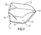
- FIG. 7 is a side view of a two-limbed version of the utensil in a slightly open position
- FIG. 8 is a perspective view of another embodiment
- FIG. 9 is a view showing the axes of rotation and longitudinal axes of the limbs.
- FIG. 10 is a view of the device shown in FIG. 1 in a closed position
- FIG. 11 is a modified view of FIG. 4 .
- FIG. 1 is a perspective right-side top view of a three-limbed version of the device 1 .
- the device includes a body section 10 which is coupled to first limb 11 in an integral manner.
- second limb 12 is coupled to body section via hinge 52
- third limb 13 is coupled to body section 10 via hinge 53 .
- Hinges 52 and 53 can be in the form of any known hinge but in this example show living hinges. Living hinges are hinges that are formed from material that is usually integral with the two components that are hinged. In this case, these hinges 52 and 53 can also have a natural spring incorporated therein based upon the material properties of the living hinge.
- First limb 11 has tooth 31 at its tip.
- Second limb 12 has tooth 32 formed at its tip.
- Third limb 13 has tooth 33 formed at its tip.
- These teeth can be in any shape but in this case, these teeth are shown ramp shaped. Alternatively, these teeth can be formed as concave having two prongs sticking out from each side.
- tooth 31 has tooth points or tips 31 . 1 and 31 . 3 and recess point 31 . 2 .
- Teeth 32 and 33 can be ramp shaped but also be formed as concave shaped teeth shown by the dashed lines. With this design, tooth 32 is formed in a concave manner or in a recessed “V” shape having tooth point 32 . 1 a recess point 32 . 2 , and another tooth point 32 . 3 . Tooth 33 can also optionally be formed with a tooth point 33 . 1 a recess point 32 . 2 and another tooth point 33 . 3 .
- second limb 12 has a longitudinal axis 104 and a rotational axis 110 while third limb 113 has a longitudinal axis 102 and a rotational axis 108 .
- Rotational axis 110 is transverse to longitudinal axis 104
- rotational axis 102 is transverse or normal to rotational axis 108 .
- this embodiment shows a device having teeth, teeth in this case are optional and are not required for operation. Therefore, it is clear that this device and therefore the invention can also be implemented without the use of teeth (see dashed lines in FIG. 4 indicating an example of an embodiment with no teeth).
- the device can be made from various materials, the most feasible embodiment of the utensil can be made of plastic or other moldable material which is safe for contact with food as a limited use-product via conventional injection molding processes.
- plastic or other moldable material which is safe for contact with food as a limited use-product via conventional injection molding processes.
- other types of materials can be used such as cornstarch, cardboard, paper, wherein these materials can constitute a more environmentally friendly version.
- Other alternative materials such as rubber or other types of materials can be used such as a composite material or metal as well.
- a non-disposable version may be stamped, folded or otherwise forged of metal.
- An edible version of this product can be made of food matter such as that derived from fibrous vegetables and molded in accordance with this invention and solidified with syrup or other coating such as that derived from oats or honey.
- FIG. 2 is a perspective, rear view of the utensil of FIG. 1 in the fully open position.
- This view shows channels which are designed to receive a user's digits
- Each of these limbs form backside channels allowing a user to insert his or her fingers or digits into these channels to control the manipulation of these limbs 11 , 12 and 13 .
- This perspective is oriented in such a way so as to be grasped by the viewer with his or her right hand such that the thumb would rest in first finger channel 21 on first limb 11 , the index finger would rest in second finger channel 22 on second limb 12 , and the middle finger of the right hand would rest in third finger channel 23 on third limb 13 .
- Second limb 12 meets the body of first limb 11 at second limb hinge 52 .
- Third limb 13 meets the body of first limb 11 at third limb hinge 53 .
- Channels 21 , 22 and 23 each have two sides and a closed end at the end of the limb opposite the body section 10
- FIG. 3 is a perspective front right-side view of the utensil of FIGS. 1 and 2 compressed to grasp food 2 .
- the user's hand is implied by the compression on the utensil but is not shown in this figure so as not to obscure the view of the utensil.
- the food item in this drawing is a chicken leg. This view shows the utensil in such a way that the user has grasped the chicken leg such that the limb teeth 31 , 32 , and 33 are behind the condile or end of the bone at the point of smallest bone diameter so as to minimize the potential for slippage.
- FIG. 4 is a perspective right side view of the utensil of FIGS. 1 , 2 , and 3 with the user's right hand shown and slightly compressed.
- Utensil 1 is held by hand 3 such that thumb 41 is in finger channel 21 , second finger 42 is in finger channel 22 of utensil limb 12 , and third finger 43 is in finger channel 23 of utensil limb 13 .
- This view also shows additional hinges 120 and 130 which are used to create additional bend points in limbs 12 and 13 respectively.
- FIG. 5 is a front view of a four-limbed version of the utensil constructed in accordance with the invention in a slightly uncompressed position.
- This version of the utensil has all the elements of the three-limbed version of figures one through four but includes finger channel 24 of fourth-limb 14 with tooth 34 at it's tip.
- FIG. 6 is a front view of a two-limbed version of the utensil constructed in accordance with the invention in a slightly open position. This version only has first-limb 11 and second-limb 12 with the aforementioned associated teeth and finger channels. Second-limb 12 can be widened to accommodate more than one finger.
- FIG. 7 is a side view of a two-limbed version of the utensil of FIG. 6 in a slightly open position. This view affords perspective of second-limb hinge 52 which would be the only hinge of this embodiment. Although the first limb is shown with a bend for ergonomics and comfort, any limb can be either straight or curved.
- FIG. 8 is a side view of a three limbed embodiment which has coil springs which are used as hinges.
- coil springs 72 and 73 wherein the first coil spring 72 is for second limb 12 and the second coil spring is for third limb 13 .
- Each of these coil springs is fixed to their respective limbs via retainer pins.
- spring 72 is secured at one end via second limb channel spring retainer pin 82 . 1 , and at the opposite end via second limb body spring retainer pin 82 . 2 .
- Spring 73 is secured at one end via third limb channel spring retainer pin 83 . 1 and at the opposite end via third limb body spring retainer pin 83 . 2 .
- limb 12 is coupled to body section 10 via a rotational hinge 62 while limb 13 is coupled to body section 10 via rotational hinge 63 .
- the device can have a snap back action which may be livelier than a living hinge of the other embodiments.
- the snap back action allows the user to have a different level of feeling and control than with the device shown in FIG. 1 which has living hinges.
- FIG. 9 is a view of the respective axes of the device wherein there is axis 100 which is the longitudinal axis of first finger 11 .
- Second finger 12 has a longitudinal axis 104 while third finger has a longitudinal axis 102 .
- Second finger 12 has a rotational axis 110 while third finger has a rotational axis 108 .
- rotational axis 110 is transverse or perpendicular to longitudinal axis 104
- rotational axis 108 is transverse or perpendicular to longitudinal axis 102 .
- transverse axis 106 which is transverse to longitudinal axis 100 , this transverse axis 106 shows that axis of rotation 110 and axis of rotation 108 are offset from 90 degrees from longitudinal axis 100 .
- This offset forms an offset angle 112 between rotational axis 108 and transverse axis 106 and an offset angle 114 between rotational axis 110 and transverse axis 106 .
- These offset angles are complementary to acute angles 113 and 115 for respective rotational angles 108 and 110 .
- the offset angles 112 and 114 are set so that second and third limbs 12 and 13 which are latitudinally offset from each other along transverse axis 106 rotate down so that their distal ends, or ends opposite their connection to body 10 , are pressed in contact with each other or adjacent to each other when the device is closed or clamped down thereby creating pressure on a food item in at least a direction shown by arrows 120 and 121 to thereby stabilize the food item against movement via these forces.
- the food item is also clamped between the limbs via the clamping forces of first limb 11 and second and third limbs 112 and 113 respectively, clamping together as shown in FIG. 10 .
- FIG. 10 shows a clamped position of the device shown in FIG. 1 .
- second limb 12 and third limb 13 clamped down towards first limb 11 respective channels 22 and 23 for limbs 12 and 13 are also shown.
- respective teeth 31 , 32 and 33 are also shown for respective limbs 11 , 12 , and 13 .
- second limb 12 and third limb 13 move towards first limb 11 in a first dimension formed for example by arrows 122 , 123 , 124 , and during this movement, second limb 12 and third limb 13 move towards each other as well in a second dimension shown by arrows 120 and 121 .
- arrows 120 and 121 show the direction of lateral pressure that is applied when the limbs are clamped down.
- arrows 122 and 123 show the direction of clamping pressure applied when the device is clamped down by a user's fingers. These arrows of pressure represent the helpful pressure that is applied when a user clamps down on the device. Because there are at least three fingers, this type of lateral pressure in the form of arrows 120 and 121 can be applied due to the offset angled settings of rotational axes 108 and 110 .
- arrows 120 and 121 are shown extending substantially perpendicular to arrows 122 and 123 which show the different pressures applied to support food in a usable manner.
- At least three limbs including a first limb 11 for receiving a first finger such as a thumb, a second limb 12 for receiving a second finger such as an index finger, and a third limb 13 for receiving a third finger.
- hinges 52 and 53 can be any type of hinges but comprise a first hinge in the form of a living hinge for allowing second limb 12 to be movable about a first rotational axis 110 . There is also a second hinge 53 in the form of a living hinge allowing third limb 13 to be movable about a second rotational axis 108 which extends at a different angle relative to first rotational axis 110 .
- living hinges are hinges that allow bendable movement of two elements formed essentially integral with each other.
- second limb 12 has a first end coupled to body section 10 and a second opposite or distal end. Second limb 12 has at least one additional hinge 120 disposed between the first end and the second opposite end, to create an articulating second limb as shown in FIG. 4 .
- the third limb 13 has a first end coupled to body section 10 and a second opposite end, wherein the third limb 13 has at least one additional hinge 130 disposed between the first end and the second or distal end, to create an articulating third limb 13 . Due to the channels formed in these teeth such as channels 21 , 22 and 23 , these limbs are easily controllable by a user's fingers.
- FIG. 11 is a modified view of FIG. 4 which discloses the angles of extension of teeth 31 , 32 , and 33 relative to their respective limbs.
- longitudinal axis 104 of second limb 12 wherein finger 42 which can be in the form of an index finger extends along this longitudinal axis in the channel for these teeth.
- Tooth 32 extends out from limb 12 along axis 134 which is offset from axis 135 via offset angle 136 .
- Axis 135 is transverse or perpendicular to longitudinal axis 104 .
- tooth 31 extends out from limb 11 along axis 109 which is offset from axis 107 via offset angle 111 .
- Axis 107 is perpendicular to longitudinal axis 100 which is the longitudinal axis of limb 11 .
- tooth 33 extends out from limb 13 along axis 131 which is offset from axis 132 via offset angle 133 .
- These offset angles 111 , 133 and 135 are such that it allows the extension of these teeth 31 , 32 , and 33 to extend out away from their respective limbs to allow a clamped down piece of food to be spaced away from a body or limb section of this device.
- the extension axis such as axes 109 , 131 and 134 for each respective tooth 31 , 32 , and 33 intersects a respective longitudinal axis 100 , 104 , and 102 for a respective limb 11 , 12 , and 13 at an acute angle such that each tooth 31 , 32 , and 33 extends out away from each limb 11 , 12 , and 13 to allow a user to grip food in a position away from each limb.
- one benefit of these offset extending teeth is that once the piece of food is clamped down upon, the food is spaced away from the body of the device so that a user can easily eat the food.
Landscapes
- Engineering & Computer Science (AREA)
- Food Science & Technology (AREA)
- Food-Manufacturing Devices (AREA)
- Table Equipment (AREA)
Priority Applications (1)
| Application Number | Priority Date | Filing Date | Title |
|---|---|---|---|
| US12/682,890 US8419092B2 (en) | 2007-08-10 | 2008-08-08 | Food handling device |
Applications Claiming Priority (3)
| Application Number | Priority Date | Filing Date | Title |
|---|---|---|---|
| US93539307P | 2007-08-10 | 2007-08-10 | |
| US12/682,890 US8419092B2 (en) | 2007-08-10 | 2008-08-08 | Food handling device |
| PCT/US2008/072711 WO2009023600A2 (en) | 2007-08-10 | 2008-08-08 | Food handling device |
Publications (2)
| Publication Number | Publication Date |
|---|---|
| US20110041349A1 US20110041349A1 (en) | 2011-02-24 |
| US8419092B2 true US8419092B2 (en) | 2013-04-16 |
Family
ID=40351425
Family Applications (1)
| Application Number | Title | Priority Date | Filing Date |
|---|---|---|---|
| US12/682,890 Expired - Fee Related US8419092B2 (en) | 2007-08-10 | 2008-08-08 | Food handling device |
Country Status (3)
| Country | Link |
|---|---|
| US (1) | US8419092B2 (de) |
| EP (1) | EP2219499A4 (de) |
| WO (1) | WO2009023600A2 (de) |
Cited By (2)
| Publication number | Priority date | Publication date | Assignee | Title |
|---|---|---|---|---|
| US20130089636A1 (en) * | 2010-06-11 | 2013-04-11 | Yulian Patzelt | Eating utensil and dispenser for providing eating utensils, and use of a sheet structure replicating the "salt cellar" origami game as an eating utensil |
| US11109665B1 (en) * | 2016-01-19 | 2021-09-07 | Sean Edward Rutherford | Point of applied force lift structure |
Families Citing this family (8)
| Publication number | Priority date | Publication date | Assignee | Title |
|---|---|---|---|---|
| US8919838B2 (en) | 2007-08-10 | 2014-12-30 | Poi Domani Marketing Products, LLC | Food handling device |
| US8590877B2 (en) * | 2008-04-21 | 2013-11-26 | Eric S. Zeitlin | Corralling utensil with associated cutting board |
| US20100314814A1 (en) * | 2009-06-10 | 2010-12-16 | Zeitlin Eric S | Compressible Corralling Utensil with Cutting Board |
| EP2525748B1 (de) * | 2010-05-06 | 2016-06-22 | MANUXA ApS | Einrichtung zur unterstützung der greiffunktion mit einer vorrichtung sowie einer befestigung der vorrichtung |
| WO2014059361A1 (en) * | 2012-10-12 | 2014-04-17 | Poi Domani Marketing Products, LLC | Food handling device |
| CN103340548A (zh) * | 2013-07-10 | 2013-10-09 | 长兴乐田栝楼开发有限公司 | 一种食物指套 |
| BR102016007392B1 (pt) * | 2016-04-02 | 2022-09-27 | Faculdades Católicas, Associação Sem Fins Lucrativos, Mantenedora Da Pontifícia Universidade Católica Do Rio De Janeiro - Puc-Rio | Dispositivo em formato de pinça e dispositivo em formato de colher |
| JP2021094197A (ja) * | 2019-12-16 | 2021-06-24 | 章子 渡邉 | トング内蔵指袋 |
Citations (36)
| Publication number | Priority date | Publication date | Assignee | Title |
|---|---|---|---|---|
| US502896A (en) * | 1893-08-08 | James s | ||
| US1156459A (en) | 1915-06-11 | 1915-10-12 | William M Brown | Egg-grip. |
| US3103213A (en) * | 1960-04-15 | 1963-09-10 | Alvin E Robinson | Bow holder |
| FR1369291A (fr) | 1963-09-17 | 1964-08-07 | Doigtier multiple | |
| US3501191A (en) | 1967-12-28 | 1970-03-17 | Leslie Darr | Tong sticks for use as chopsticks and the like |
| US3593803A (en) * | 1968-12-27 | 1971-07-20 | Charles W Ibach | Gardener{3 s glove |
| US4038787A (en) * | 1976-03-01 | 1977-08-02 | Rb Products Corporation | Abrasive glove |
| US4261608A (en) | 1979-02-23 | 1981-04-14 | Bradshaw Marilyn J | Self-feeding tongs |
| JPS62114016A (ja) | 1985-11-13 | 1987-05-25 | Yokogawa Electric Corp | 多機能型ノブ |
| US4675914A (en) * | 1986-05-12 | 1987-06-30 | Rodger Mitchell | Hard-grip glove |
| US4728130A (en) | 1987-01-12 | 1988-03-01 | Corzine George S | Locking assembly for push-on fittings |
| US4751747A (en) * | 1986-06-24 | 1988-06-21 | Janice Banks | Finger and thumb heat protector |
| US4867246A (en) * | 1988-03-03 | 1989-09-19 | Kiger Carrie A | Gardening glove with attached fingertip cups |
| JPH02138651A (ja) | 1988-11-18 | 1990-05-28 | Fujitsu Ltd | 起動信号受信方式 |
| US4961568A (en) * | 1989-04-04 | 1990-10-09 | Douglas W. Clark | Exercising and stretching a person's finger joints |
| US5359840A (en) * | 1994-01-04 | 1994-11-01 | Costar Donald G | Combination handrake, scoop, grasping tool and method of use |
| JPH08395A (ja) | 1994-06-16 | 1996-01-09 | Okamura Corp | 椅子の肘当ての上下調整装置 |
| US5568957A (en) * | 1992-02-12 | 1996-10-29 | Haugs; Audun | Pressure actuated gripping apparatus and method |
| US5649728A (en) | 1996-08-02 | 1997-07-22 | Warthen; Benjamin R. | Tong-like eating utensil |
| US5653488A (en) | 1995-12-08 | 1997-08-05 | Ordonez; Gonzalo A. | Article for manipulating food |
| US5661853A (en) * | 1995-12-18 | 1997-09-02 | Wilmot; Elizabeth C. | Unitary fingertip protector |
| US5709423A (en) | 1996-05-17 | 1998-01-20 | Romero; Ivan | Food gripper utensil |
| US5749097A (en) * | 1997-03-10 | 1998-05-12 | Garrett-Roe; Anita Mallory | Three digit fingernail protector |
| US5848928A (en) | 1996-12-30 | 1998-12-15 | Wong; Ken E. | Finger puppet eating utensil |
| KR19990037804U (ko) | 1998-03-13 | 1999-10-15 | 김준규 | 손으로 음식을 집어 먹기 위한 위생 손가락커버 |
| FR2786678A1 (fr) | 1998-12-02 | 2000-06-09 | Frederic Pintus | Instrument de prehension |
| US6089631A (en) | 1999-10-01 | 2000-07-18 | Lentrade, Inc. | Tongs for handling food |
| US6276734B1 (en) | 2000-02-04 | 2001-08-21 | Rory F. Krieger | Utilitarian combination utensil |
| US20030131393A1 (en) * | 2002-01-14 | 2003-07-17 | Votolato Earl J. | Utensil for eliminating bare hand handling of sensitive material |
| US20030190997A1 (en) * | 2002-04-03 | 2003-10-09 | Siek Jason L. | Hand exerciser |
| US6918137B2 (en) * | 2001-06-08 | 2005-07-19 | Sandra S. Fowler | Protective hand guard |
| US6944914B2 (en) * | 2001-10-24 | 2005-09-20 | Tillim Stephen L | Handle and forceps/tweezers and method and apparatus for designing the like |
| WO2006046086A1 (en) | 2004-10-25 | 2006-05-04 | Louis Vermeirsch | Chopsticks holder |
| US20060249967A1 (en) | 2005-04-14 | 2006-11-09 | Carolina Raymond H | Wing holder |
| US7165270B2 (en) | 2004-01-23 | 2007-01-23 | Deyoung Perry R | Food holder |
| WO2007117067A1 (en) | 2006-04-12 | 2007-10-18 | Kyungsung University Office Of Industry - Academy Cooperation | A disposable napkin |
Family Cites Families (3)
| Publication number | Priority date | Publication date | Assignee | Title |
|---|---|---|---|---|
| JPS62114016U (de) * | 1986-01-09 | 1987-07-20 | ||
| JPH02138651U (de) * | 1989-04-18 | 1990-11-20 | ||
| JPH08395U (ja) * | 1991-05-22 | 1996-02-27 | 富植 張 | 摘食用指カバー |
-
2008
- 2008-08-08 WO PCT/US2008/072711 patent/WO2009023600A2/en not_active Ceased
- 2008-08-08 US US12/682,890 patent/US8419092B2/en not_active Expired - Fee Related
- 2008-08-08 EP EP08797555A patent/EP2219499A4/de not_active Ceased
Patent Citations (37)
| Publication number | Priority date | Publication date | Assignee | Title |
|---|---|---|---|---|
| US502896A (en) * | 1893-08-08 | James s | ||
| US1156459A (en) | 1915-06-11 | 1915-10-12 | William M Brown | Egg-grip. |
| US3103213A (en) * | 1960-04-15 | 1963-09-10 | Alvin E Robinson | Bow holder |
| FR1369291A (fr) | 1963-09-17 | 1964-08-07 | Doigtier multiple | |
| US3501191A (en) | 1967-12-28 | 1970-03-17 | Leslie Darr | Tong sticks for use as chopsticks and the like |
| US3593803A (en) * | 1968-12-27 | 1971-07-20 | Charles W Ibach | Gardener{3 s glove |
| US4038787A (en) * | 1976-03-01 | 1977-08-02 | Rb Products Corporation | Abrasive glove |
| US4261608A (en) | 1979-02-23 | 1981-04-14 | Bradshaw Marilyn J | Self-feeding tongs |
| JPS62114016A (ja) | 1985-11-13 | 1987-05-25 | Yokogawa Electric Corp | 多機能型ノブ |
| US4675914A (en) * | 1986-05-12 | 1987-06-30 | Rodger Mitchell | Hard-grip glove |
| US4751747A (en) * | 1986-06-24 | 1988-06-21 | Janice Banks | Finger and thumb heat protector |
| US4728130A (en) | 1987-01-12 | 1988-03-01 | Corzine George S | Locking assembly for push-on fittings |
| US4867246A (en) * | 1988-03-03 | 1989-09-19 | Kiger Carrie A | Gardening glove with attached fingertip cups |
| JPH02138651A (ja) | 1988-11-18 | 1990-05-28 | Fujitsu Ltd | 起動信号受信方式 |
| US4961568A (en) * | 1989-04-04 | 1990-10-09 | Douglas W. Clark | Exercising and stretching a person's finger joints |
| US5568957A (en) * | 1992-02-12 | 1996-10-29 | Haugs; Audun | Pressure actuated gripping apparatus and method |
| US5359840A (en) * | 1994-01-04 | 1994-11-01 | Costar Donald G | Combination handrake, scoop, grasping tool and method of use |
| JPH08395A (ja) | 1994-06-16 | 1996-01-09 | Okamura Corp | 椅子の肘当ての上下調整装置 |
| US5653488A (en) | 1995-12-08 | 1997-08-05 | Ordonez; Gonzalo A. | Article for manipulating food |
| US5661853A (en) * | 1995-12-18 | 1997-09-02 | Wilmot; Elizabeth C. | Unitary fingertip protector |
| US5709423A (en) | 1996-05-17 | 1998-01-20 | Romero; Ivan | Food gripper utensil |
| US5649728A (en) | 1996-08-02 | 1997-07-22 | Warthen; Benjamin R. | Tong-like eating utensil |
| US5848928A (en) | 1996-12-30 | 1998-12-15 | Wong; Ken E. | Finger puppet eating utensil |
| US5749097A (en) * | 1997-03-10 | 1998-05-12 | Garrett-Roe; Anita Mallory | Three digit fingernail protector |
| KR19990037804U (ko) | 1998-03-13 | 1999-10-15 | 김준규 | 손으로 음식을 집어 먹기 위한 위생 손가락커버 |
| FR2786678A1 (fr) | 1998-12-02 | 2000-06-09 | Frederic Pintus | Instrument de prehension |
| US6089631A (en) | 1999-10-01 | 2000-07-18 | Lentrade, Inc. | Tongs for handling food |
| US6276734B1 (en) | 2000-02-04 | 2001-08-21 | Rory F. Krieger | Utilitarian combination utensil |
| US6918137B2 (en) * | 2001-06-08 | 2005-07-19 | Sandra S. Fowler | Protective hand guard |
| US6944914B2 (en) * | 2001-10-24 | 2005-09-20 | Tillim Stephen L | Handle and forceps/tweezers and method and apparatus for designing the like |
| US20030131393A1 (en) * | 2002-01-14 | 2003-07-17 | Votolato Earl J. | Utensil for eliminating bare hand handling of sensitive material |
| US20030190997A1 (en) * | 2002-04-03 | 2003-10-09 | Siek Jason L. | Hand exerciser |
| US7165270B2 (en) | 2004-01-23 | 2007-01-23 | Deyoung Perry R | Food holder |
| WO2006046086A1 (en) | 2004-10-25 | 2006-05-04 | Louis Vermeirsch | Chopsticks holder |
| US20060249967A1 (en) | 2005-04-14 | 2006-11-09 | Carolina Raymond H | Wing holder |
| US7287791B2 (en) | 2005-04-14 | 2007-10-30 | Carolina Raymond H | Wing holder |
| WO2007117067A1 (en) | 2006-04-12 | 2007-10-18 | Kyungsung University Office Of Industry - Academy Cooperation | A disposable napkin |
Non-Patent Citations (4)
| Title |
|---|
| International Search Report for PCT/US2008/072711 Dated Feb. 26, 2009. |
| Supplementary European Search Report dated Oct. 19, 2011, 6 pages. |
| Translation of FR1369291 (FR1369291 previously submitted on Nov. 25, 2011). |
| Translation of FR278678 (FR278678 previously Submitted on Nov. 25, 2011). |
Cited By (2)
| Publication number | Priority date | Publication date | Assignee | Title |
|---|---|---|---|---|
| US20130089636A1 (en) * | 2010-06-11 | 2013-04-11 | Yulian Patzelt | Eating utensil and dispenser for providing eating utensils, and use of a sheet structure replicating the "salt cellar" origami game as an eating utensil |
| US11109665B1 (en) * | 2016-01-19 | 2021-09-07 | Sean Edward Rutherford | Point of applied force lift structure |
Also Published As
| Publication number | Publication date |
|---|---|
| WO2009023600A3 (en) | 2009-04-16 |
| EP2219499A4 (de) | 2011-11-30 |
| EP2219499A2 (de) | 2010-08-25 |
| WO2009023600A2 (en) | 2009-02-19 |
| US20110041349A1 (en) | 2011-02-24 |
Similar Documents
| Publication | Publication Date | Title |
|---|---|---|
| US8419092B2 (en) | Food handling device | |
| US8919838B2 (en) | Food handling device | |
| US6276734B1 (en) | Utilitarian combination utensil | |
| US7805843B2 (en) | Eating utensil | |
| US8132689B2 (en) | Cookware handle with a hollow structure | |
| US20200163475A1 (en) | Spoon | |
| US6094780A (en) | Ergonomic handle for terminal insertion tool | |
| JPH07502906A (ja) | 手に障害のある者が使用する食事用具 | |
| JP2022549016A (ja) | 把持具 | |
| JP2008520334A (ja) | 飲食物挟持具 | |
| USD474653S1 (en) | Elastomeric chopstick retaining device | |
| WO2014059361A1 (en) | Food handling device | |
| US8727408B1 (en) | Tongs including tapered fingers | |
| US8556115B2 (en) | Surgical instrument container assembly with elliptical softgrip handle assembly | |
| JP2005111959A (ja) | 手障害者用補助具 | |
| KR100720828B1 (ko) | 집게형 젓가락 | |
| KR101012813B1 (ko) | 개량형 젓가락 | |
| WO2019178391A1 (en) | Forearm, wrist and hand stretching device | |
| KR102414442B1 (ko) | 보조지지부를 포함하는 음식물용 집게 | |
| USD1104751S1 (en) | Can grip device | |
| CN108209440A (zh) | 具有固定带的手握式筷子柄 | |
| KR20140148252A (ko) | 손가락 끼움식 젓가락 | |
| US7887112B1 (en) | Food clip utensil | |
| JP3061045U (ja) | 箸 | |
| JPH07213406A (ja) | 食事用具 |
Legal Events
| Date | Code | Title | Description |
|---|---|---|---|
| AS | Assignment |
Owner name: POIDOMANI INNOVATIONS, INC., NEW YORK Free format text: ASSIGNMENT OF ASSIGNORS INTEREST;ASSIGNORS:ZIMMERMANN, ERIC;FERRARA, DANIEL J., JR.;SIGNING DATES FROM 20081202 TO 20090124;REEL/FRAME:022269/0083 |
|
| STCF | Information on status: patent grant |
Free format text: PATENTED CASE |
|
| REMI | Maintenance fee reminder mailed | ||
| FPAY | Fee payment |
Year of fee payment: 4 |
|
| SULP | Surcharge for late payment | ||
| MAFP | Maintenance fee payment |
Free format text: PAYMENT OF MAINTENANCE FEE, 8TH YR, SMALL ENTITY (ORIGINAL EVENT CODE: M2552); ENTITY STATUS OF PATENT OWNER: SMALL ENTITY Year of fee payment: 8 |
|
| FEPP | Fee payment procedure |
Free format text: MAINTENANCE FEE REMINDER MAILED (ORIGINAL EVENT CODE: REM.); ENTITY STATUS OF PATENT OWNER: SMALL ENTITY |
|
| LAPS | Lapse for failure to pay maintenance fees |
Free format text: PATENT EXPIRED FOR FAILURE TO PAY MAINTENANCE FEES (ORIGINAL EVENT CODE: EXP.); ENTITY STATUS OF PATENT OWNER: SMALL ENTITY |
|
| STCH | Information on status: patent discontinuation |
Free format text: PATENT EXPIRED DUE TO NONPAYMENT OF MAINTENANCE FEES UNDER 37 CFR 1.362 |
|
| FP | Lapsed due to failure to pay maintenance fee |
Effective date: 20250416 |