US8326476B2 - Electrically powered vehicle - Google Patents
Electrically powered vehicle Download PDFInfo
- Publication number
- US8326476B2 US8326476B2 US12/669,747 US66974708A US8326476B2 US 8326476 B2 US8326476 B2 US 8326476B2 US 66974708 A US66974708 A US 66974708A US 8326476 B2 US8326476 B2 US 8326476B2
- Authority
- US
- United States
- Prior art keywords
- charging
- unit
- control unit
- electric power
- abnormality
- Prior art date
- Legal status (The legal status is an assumption and is not a legal conclusion. Google has not performed a legal analysis and makes no representation as to the accuracy of the status listed.)
- Active, expires
Links
Images


Classifications
-
- B—PERFORMING OPERATIONS; TRANSPORTING
- B60—VEHICLES IN GENERAL
- B60L—PROPULSION OF ELECTRICALLY-PROPELLED VEHICLES; SUPPLYING ELECTRIC POWER FOR AUXILIARY EQUIPMENT OF ELECTRICALLY-PROPELLED VEHICLES; ELECTRODYNAMIC BRAKE SYSTEMS FOR VEHICLES IN GENERAL; MAGNETIC SUSPENSION OR LEVITATION FOR VEHICLES; MONITORING OPERATING VARIABLES OF ELECTRICALLY-PROPELLED VEHICLES; ELECTRIC SAFETY DEVICES FOR ELECTRICALLY-PROPELLED VEHICLES
- B60L3/00—Electric devices on electrically-propelled vehicles for safety purposes; Monitoring operating variables, e.g. speed, deceleration or energy consumption
- B60L3/0092—Electric devices on electrically-propelled vehicles for safety purposes; Monitoring operating variables, e.g. speed, deceleration or energy consumption with use of redundant elements for safety purposes
-
- B—PERFORMING OPERATIONS; TRANSPORTING
- B60—VEHICLES IN GENERAL
- B60L—PROPULSION OF ELECTRICALLY-PROPELLED VEHICLES; SUPPLYING ELECTRIC POWER FOR AUXILIARY EQUIPMENT OF ELECTRICALLY-PROPELLED VEHICLES; ELECTRODYNAMIC BRAKE SYSTEMS FOR VEHICLES IN GENERAL; MAGNETIC SUSPENSION OR LEVITATION FOR VEHICLES; MONITORING OPERATING VARIABLES OF ELECTRICALLY-PROPELLED VEHICLES; ELECTRIC SAFETY DEVICES FOR ELECTRICALLY-PROPELLED VEHICLES
- B60L3/00—Electric devices on electrically-propelled vehicles for safety purposes; Monitoring operating variables, e.g. speed, deceleration or energy consumption
- B60L3/0023—Detecting, eliminating, remedying or compensating for drive train abnormalities, e.g. failures within the drive train
- B60L3/0046—Detecting, eliminating, remedying or compensating for drive train abnormalities, e.g. failures within the drive train relating to electric energy storage systems, e.g. batteries or capacitors
-
- B—PERFORMING OPERATIONS; TRANSPORTING
- B60—VEHICLES IN GENERAL
- B60L—PROPULSION OF ELECTRICALLY-PROPELLED VEHICLES; SUPPLYING ELECTRIC POWER FOR AUXILIARY EQUIPMENT OF ELECTRICALLY-PROPELLED VEHICLES; ELECTRODYNAMIC BRAKE SYSTEMS FOR VEHICLES IN GENERAL; MAGNETIC SUSPENSION OR LEVITATION FOR VEHICLES; MONITORING OPERATING VARIABLES OF ELECTRICALLY-PROPELLED VEHICLES; ELECTRIC SAFETY DEVICES FOR ELECTRICALLY-PROPELLED VEHICLES
- B60L3/00—Electric devices on electrically-propelled vehicles for safety purposes; Monitoring operating variables, e.g. speed, deceleration or energy consumption
- B60L3/0023—Detecting, eliminating, remedying or compensating for drive train abnormalities, e.g. failures within the drive train
- B60L3/0053—Detecting, eliminating, remedying or compensating for drive train abnormalities, e.g. failures within the drive train relating to fuel cells
-
- B—PERFORMING OPERATIONS; TRANSPORTING
- B60—VEHICLES IN GENERAL
- B60L—PROPULSION OF ELECTRICALLY-PROPELLED VEHICLES; SUPPLYING ELECTRIC POWER FOR AUXILIARY EQUIPMENT OF ELECTRICALLY-PROPELLED VEHICLES; ELECTRODYNAMIC BRAKE SYSTEMS FOR VEHICLES IN GENERAL; MAGNETIC SUSPENSION OR LEVITATION FOR VEHICLES; MONITORING OPERATING VARIABLES OF ELECTRICALLY-PROPELLED VEHICLES; ELECTRIC SAFETY DEVICES FOR ELECTRICALLY-PROPELLED VEHICLES
- B60L50/00—Electric propulsion with power supplied within the vehicle
- B60L50/10—Electric propulsion with power supplied within the vehicle using propulsion power supplied by engine-driven generators, e.g. generators driven by combustion engines
- B60L50/16—Electric propulsion with power supplied within the vehicle using propulsion power supplied by engine-driven generators, e.g. generators driven by combustion engines with provision for separate direct mechanical propulsion
-
- B—PERFORMING OPERATIONS; TRANSPORTING
- B60—VEHICLES IN GENERAL
- B60L—PROPULSION OF ELECTRICALLY-PROPELLED VEHICLES; SUPPLYING ELECTRIC POWER FOR AUXILIARY EQUIPMENT OF ELECTRICALLY-PROPELLED VEHICLES; ELECTRODYNAMIC BRAKE SYSTEMS FOR VEHICLES IN GENERAL; MAGNETIC SUSPENSION OR LEVITATION FOR VEHICLES; MONITORING OPERATING VARIABLES OF ELECTRICALLY-PROPELLED VEHICLES; ELECTRIC SAFETY DEVICES FOR ELECTRICALLY-PROPELLED VEHICLES
- B60L50/00—Electric propulsion with power supplied within the vehicle
- B60L50/50—Electric propulsion with power supplied within the vehicle using propulsion power supplied by batteries or fuel cells
- B60L50/60—Electric propulsion with power supplied within the vehicle using propulsion power supplied by batteries or fuel cells using power supplied by batteries
- B60L50/61—Electric propulsion with power supplied within the vehicle using propulsion power supplied by batteries or fuel cells using power supplied by batteries by batteries charged by engine-driven generators, e.g. series hybrid electric vehicles
-
- B—PERFORMING OPERATIONS; TRANSPORTING
- B60—VEHICLES IN GENERAL
- B60L—PROPULSION OF ELECTRICALLY-PROPELLED VEHICLES; SUPPLYING ELECTRIC POWER FOR AUXILIARY EQUIPMENT OF ELECTRICALLY-PROPELLED VEHICLES; ELECTRODYNAMIC BRAKE SYSTEMS FOR VEHICLES IN GENERAL; MAGNETIC SUSPENSION OR LEVITATION FOR VEHICLES; MONITORING OPERATING VARIABLES OF ELECTRICALLY-PROPELLED VEHICLES; ELECTRIC SAFETY DEVICES FOR ELECTRICALLY-PROPELLED VEHICLES
- B60L53/00—Methods of charging batteries, specially adapted for electric vehicles; Charging stations or on-board charging equipment therefor; Exchange of energy storage elements in electric vehicles
- B60L53/60—Monitoring or controlling charging stations
- B60L53/63—Monitoring or controlling charging stations in response to network capacity
-
- B—PERFORMING OPERATIONS; TRANSPORTING
- B60—VEHICLES IN GENERAL
- B60L—PROPULSION OF ELECTRICALLY-PROPELLED VEHICLES; SUPPLYING ELECTRIC POWER FOR AUXILIARY EQUIPMENT OF ELECTRICALLY-PROPELLED VEHICLES; ELECTRODYNAMIC BRAKE SYSTEMS FOR VEHICLES IN GENERAL; MAGNETIC SUSPENSION OR LEVITATION FOR VEHICLES; MONITORING OPERATING VARIABLES OF ELECTRICALLY-PROPELLED VEHICLES; ELECTRIC SAFETY DEVICES FOR ELECTRICALLY-PROPELLED VEHICLES
- B60L53/00—Methods of charging batteries, specially adapted for electric vehicles; Charging stations or on-board charging equipment therefor; Exchange of energy storage elements in electric vehicles
- B60L53/60—Monitoring or controlling charging stations
- B60L53/64—Optimising energy costs, e.g. responding to electricity rates
-
- B—PERFORMING OPERATIONS; TRANSPORTING
- B60—VEHICLES IN GENERAL
- B60L—PROPULSION OF ELECTRICALLY-PROPELLED VEHICLES; SUPPLYING ELECTRIC POWER FOR AUXILIARY EQUIPMENT OF ELECTRICALLY-PROPELLED VEHICLES; ELECTRODYNAMIC BRAKE SYSTEMS FOR VEHICLES IN GENERAL; MAGNETIC SUSPENSION OR LEVITATION FOR VEHICLES; MONITORING OPERATING VARIABLES OF ELECTRICALLY-PROPELLED VEHICLES; ELECTRIC SAFETY DEVICES FOR ELECTRICALLY-PROPELLED VEHICLES
- B60L58/00—Methods or circuit arrangements for monitoring or controlling batteries or fuel cells, specially adapted for electric vehicles
- B60L58/10—Methods or circuit arrangements for monitoring or controlling batteries or fuel cells, specially adapted for electric vehicles for monitoring or controlling batteries
- B60L58/12—Methods or circuit arrangements for monitoring or controlling batteries or fuel cells, specially adapted for electric vehicles for monitoring or controlling batteries responding to state of charge [SoC]
-
- H—ELECTRICITY
- H02—GENERATION; CONVERSION OR DISTRIBUTION OF ELECTRIC POWER
- H02J—CIRCUIT ARRANGEMENTS OR SYSTEMS FOR SUPPLYING OR DISTRIBUTING ELECTRIC POWER; SYSTEMS FOR STORING ELECTRIC ENERGY
- H02J1/00—Circuit arrangements for dc mains or dc distribution networks
- H02J1/08—Three-wire systems; Systems having more than three wires
-
- B—PERFORMING OPERATIONS; TRANSPORTING
- B60—VEHICLES IN GENERAL
- B60L—PROPULSION OF ELECTRICALLY-PROPELLED VEHICLES; SUPPLYING ELECTRIC POWER FOR AUXILIARY EQUIPMENT OF ELECTRICALLY-PROPELLED VEHICLES; ELECTRODYNAMIC BRAKE SYSTEMS FOR VEHICLES IN GENERAL; MAGNETIC SUSPENSION OR LEVITATION FOR VEHICLES; MONITORING OPERATING VARIABLES OF ELECTRICALLY-PROPELLED VEHICLES; ELECTRIC SAFETY DEVICES FOR ELECTRICALLY-PROPELLED VEHICLES
- B60L2250/00—Driver interactions
- B60L2250/16—Driver interactions by display
-
- H—ELECTRICITY
- H02—GENERATION; CONVERSION OR DISTRIBUTION OF ELECTRIC POWER
- H02J—CIRCUIT ARRANGEMENTS OR SYSTEMS FOR SUPPLYING OR DISTRIBUTING ELECTRIC POWER; SYSTEMS FOR STORING ELECTRIC ENERGY
- H02J7/00—Circuit arrangements for charging or depolarising batteries or for supplying loads from batteries
- H02J7/34—Parallel operation in networks using both storage and other dc sources, e.g. providing buffering
- H02J7/342—The other DC source being a battery actively interacting with the first one, i.e. battery to battery charging
-
- Y—GENERAL TAGGING OF NEW TECHNOLOGICAL DEVELOPMENTS; GENERAL TAGGING OF CROSS-SECTIONAL TECHNOLOGIES SPANNING OVER SEVERAL SECTIONS OF THE IPC; TECHNICAL SUBJECTS COVERED BY FORMER USPC CROSS-REFERENCE ART COLLECTIONS [XRACs] AND DIGESTS
- Y02—TECHNOLOGIES OR APPLICATIONS FOR MITIGATION OR ADAPTATION AGAINST CLIMATE CHANGE
- Y02E—REDUCTION OF GREENHOUSE GAS [GHG] EMISSIONS, RELATED TO ENERGY GENERATION, TRANSMISSION OR DISTRIBUTION
- Y02E60/00—Enabling technologies; Technologies with a potential or indirect contribution to GHG emissions mitigation
-
- Y—GENERAL TAGGING OF NEW TECHNOLOGICAL DEVELOPMENTS; GENERAL TAGGING OF CROSS-SECTIONAL TECHNOLOGIES SPANNING OVER SEVERAL SECTIONS OF THE IPC; TECHNICAL SUBJECTS COVERED BY FORMER USPC CROSS-REFERENCE ART COLLECTIONS [XRACs] AND DIGESTS
- Y02—TECHNOLOGIES OR APPLICATIONS FOR MITIGATION OR ADAPTATION AGAINST CLIMATE CHANGE
- Y02T—CLIMATE CHANGE MITIGATION TECHNOLOGIES RELATED TO TRANSPORTATION
- Y02T10/00—Road transport of goods or passengers
- Y02T10/60—Other road transportation technologies with climate change mitigation effect
- Y02T10/62—Hybrid vehicles
-
- Y—GENERAL TAGGING OF NEW TECHNOLOGICAL DEVELOPMENTS; GENERAL TAGGING OF CROSS-SECTIONAL TECHNOLOGIES SPANNING OVER SEVERAL SECTIONS OF THE IPC; TECHNICAL SUBJECTS COVERED BY FORMER USPC CROSS-REFERENCE ART COLLECTIONS [XRACs] AND DIGESTS
- Y02—TECHNOLOGIES OR APPLICATIONS FOR MITIGATION OR ADAPTATION AGAINST CLIMATE CHANGE
- Y02T—CLIMATE CHANGE MITIGATION TECHNOLOGIES RELATED TO TRANSPORTATION
- Y02T10/00—Road transport of goods or passengers
- Y02T10/60—Other road transportation technologies with climate change mitigation effect
- Y02T10/70—Energy storage systems for electromobility, e.g. batteries
-
- Y—GENERAL TAGGING OF NEW TECHNOLOGICAL DEVELOPMENTS; GENERAL TAGGING OF CROSS-SECTIONAL TECHNOLOGIES SPANNING OVER SEVERAL SECTIONS OF THE IPC; TECHNICAL SUBJECTS COVERED BY FORMER USPC CROSS-REFERENCE ART COLLECTIONS [XRACs] AND DIGESTS
- Y02—TECHNOLOGIES OR APPLICATIONS FOR MITIGATION OR ADAPTATION AGAINST CLIMATE CHANGE
- Y02T—CLIMATE CHANGE MITIGATION TECHNOLOGIES RELATED TO TRANSPORTATION
- Y02T10/00—Road transport of goods or passengers
- Y02T10/60—Other road transportation technologies with climate change mitigation effect
- Y02T10/7072—Electromobility specific charging systems or methods for batteries, ultracapacitors, supercapacitors or double-layer capacitors
-
- Y—GENERAL TAGGING OF NEW TECHNOLOGICAL DEVELOPMENTS; GENERAL TAGGING OF CROSS-SECTIONAL TECHNOLOGIES SPANNING OVER SEVERAL SECTIONS OF THE IPC; TECHNICAL SUBJECTS COVERED BY FORMER USPC CROSS-REFERENCE ART COLLECTIONS [XRACs] AND DIGESTS
- Y02—TECHNOLOGIES OR APPLICATIONS FOR MITIGATION OR ADAPTATION AGAINST CLIMATE CHANGE
- Y02T—CLIMATE CHANGE MITIGATION TECHNOLOGIES RELATED TO TRANSPORTATION
- Y02T90/00—Enabling technologies or technologies with a potential or indirect contribution to GHG emissions mitigation
- Y02T90/10—Technologies relating to charging of electric vehicles
- Y02T90/12—Electric charging stations
-
- Y—GENERAL TAGGING OF NEW TECHNOLOGICAL DEVELOPMENTS; GENERAL TAGGING OF CROSS-SECTIONAL TECHNOLOGIES SPANNING OVER SEVERAL SECTIONS OF THE IPC; TECHNICAL SUBJECTS COVERED BY FORMER USPC CROSS-REFERENCE ART COLLECTIONS [XRACs] AND DIGESTS
- Y02—TECHNOLOGIES OR APPLICATIONS FOR MITIGATION OR ADAPTATION AGAINST CLIMATE CHANGE
- Y02T—CLIMATE CHANGE MITIGATION TECHNOLOGIES RELATED TO TRANSPORTATION
- Y02T90/00—Enabling technologies or technologies with a potential or indirect contribution to GHG emissions mitigation
- Y02T90/10—Technologies relating to charging of electric vehicles
- Y02T90/14—Plug-in electric vehicles
-
- Y—GENERAL TAGGING OF NEW TECHNOLOGICAL DEVELOPMENTS; GENERAL TAGGING OF CROSS-SECTIONAL TECHNOLOGIES SPANNING OVER SEVERAL SECTIONS OF THE IPC; TECHNICAL SUBJECTS COVERED BY FORMER USPC CROSS-REFERENCE ART COLLECTIONS [XRACs] AND DIGESTS
- Y02—TECHNOLOGIES OR APPLICATIONS FOR MITIGATION OR ADAPTATION AGAINST CLIMATE CHANGE
- Y02T—CLIMATE CHANGE MITIGATION TECHNOLOGIES RELATED TO TRANSPORTATION
- Y02T90/00—Enabling technologies or technologies with a potential or indirect contribution to GHG emissions mitigation
- Y02T90/10—Technologies relating to charging of electric vehicles
- Y02T90/16—Information or communication technologies improving the operation of electric vehicles
- Y02T90/167—Systems integrating technologies related to power network operation and communication or information technologies for supporting the interoperability of electric or hybrid vehicles, i.e. smartgrids as interface for battery charging of electric vehicles [EV] or hybrid vehicles [HEV]
-
- Y—GENERAL TAGGING OF NEW TECHNOLOGICAL DEVELOPMENTS; GENERAL TAGGING OF CROSS-SECTIONAL TECHNOLOGIES SPANNING OVER SEVERAL SECTIONS OF THE IPC; TECHNICAL SUBJECTS COVERED BY FORMER USPC CROSS-REFERENCE ART COLLECTIONS [XRACs] AND DIGESTS
- Y02—TECHNOLOGIES OR APPLICATIONS FOR MITIGATION OR ADAPTATION AGAINST CLIMATE CHANGE
- Y02T—CLIMATE CHANGE MITIGATION TECHNOLOGIES RELATED TO TRANSPORTATION
- Y02T90/00—Enabling technologies or technologies with a potential or indirect contribution to GHG emissions mitigation
- Y02T90/40—Application of hydrogen technology to transportation, e.g. using fuel cells
-
- Y—GENERAL TAGGING OF NEW TECHNOLOGICAL DEVELOPMENTS; GENERAL TAGGING OF CROSS-SECTIONAL TECHNOLOGIES SPANNING OVER SEVERAL SECTIONS OF THE IPC; TECHNICAL SUBJECTS COVERED BY FORMER USPC CROSS-REFERENCE ART COLLECTIONS [XRACs] AND DIGESTS
- Y04—INFORMATION OR COMMUNICATION TECHNOLOGIES HAVING AN IMPACT ON OTHER TECHNOLOGY AREAS
- Y04S—SYSTEMS INTEGRATING TECHNOLOGIES RELATED TO POWER NETWORK OPERATION, COMMUNICATION OR INFORMATION TECHNOLOGIES FOR IMPROVING THE ELECTRICAL POWER GENERATION, TRANSMISSION, DISTRIBUTION, MANAGEMENT OR USAGE, i.e. SMART GRIDS
- Y04S10/00—Systems supporting electrical power generation, transmission or distribution
- Y04S10/12—Monitoring or controlling equipment for energy generation units, e.g. distributed energy generation [DER] or load-side generation
- Y04S10/126—Monitoring or controlling equipment for energy generation units, e.g. distributed energy generation [DER] or load-side generation the energy generation units being or involving electric vehicles [EV] or hybrid vehicles [HEV], i.e. power aggregation of EV or HEV, vehicle to grid arrangements [V2G]
-
- Y—GENERAL TAGGING OF NEW TECHNOLOGICAL DEVELOPMENTS; GENERAL TAGGING OF CROSS-SECTIONAL TECHNOLOGIES SPANNING OVER SEVERAL SECTIONS OF THE IPC; TECHNICAL SUBJECTS COVERED BY FORMER USPC CROSS-REFERENCE ART COLLECTIONS [XRACs] AND DIGESTS
- Y04—INFORMATION OR COMMUNICATION TECHNOLOGIES HAVING AN IMPACT ON OTHER TECHNOLOGY AREAS
- Y04S—SYSTEMS INTEGRATING TECHNOLOGIES RELATED TO POWER NETWORK OPERATION, COMMUNICATION OR INFORMATION TECHNOLOGIES FOR IMPROVING THE ELECTRICAL POWER GENERATION, TRANSMISSION, DISTRIBUTION, MANAGEMENT OR USAGE, i.e. SMART GRIDS
- Y04S30/00—Systems supporting specific end-user applications in the sector of transportation
- Y04S30/10—Systems supporting the interoperability of electric or hybrid vehicles
- Y04S30/14—Details associated with the interoperability, e.g. vehicle recognition, authentication, identification or billing
Definitions
- the present invention relates to an electrically powered vehicle, in particular, an electrically powered vehicle that can be charged by an external power source.
- Electrically powered vehicles each have a power storage device (for example, a secondary battery, a capacitor, or the like) mounted thereon, and travel using driving force generated from electric power stored in the power storage device.
- the electrically powered vehicles include, for example, an electric vehicle, a hybrid vehicle, a fuel cell vehicle, and the like.
- a fee for an amount of electric power required in charging the power storage device is cheaper. If fee for usage of electric power in midnight is cheaper than that in daytime, expenses for charging can be reduced by, for example, charging the power storage device of the electrically powered vehicle during a period of midnight power.
- a way considered and utilized to solve such a problem is to start charging the power storage device of the vehicle at charging start time designated by the user.
- Japanese Patent Laying-Open No. 7-123599 discloses a charging control device for securely charging a power storage device at charging start time in the way described above.
- the charging control device checks for problems in the charging system at the moment when the timer is set, and outputs a warning if the charging system has a problem. With this, inexecution of the charging by the problem having existed when the timer was set, can be prevented after the start of charging.
- Japanese Patent Laying-Open No. 7-123599 discloses that the charging control device checks for problems at the moment when the timer starts to measure time and at the moment when the timer ends the measurement. However, it never discloses a specific process of the control device when a problem (such as electric power failure) occurs during a period of time from the moment of starting the time measurement to the moment of ending it. In such a case, it is considered that the problem is not detected until the timer ends the time measurement. If the problem in the charging system remains, adverse effects are concerned over not only the charging device but also the vehicle.
- a problem such as electric power failure
- An object of the present invention is to provide an electrically powered vehicle that can be charged by an external power source and can detect an abnormality in its charging system quickly.
- the present invention provides an electrically powered vehicle chargeable by an external power source.
- the electrically powered vehicle includes a power storage device, a charging device, a start time setting unit, a start instructing unit, a charging control unit, and an abnormality monitoring unit.
- the power storage device stores electric power used to generate driving force of the electrically powered vehicle.
- the charging device charges the power storage device using electric power supplied from the external power source.
- the start time setting unit receives at least one of programmed start time and programmed end time and sets charging start time.
- the start instructing unit outputs a start instruction to start to charge the power storage device, when the present time reaches the charging start time set by the start time setting unit.
- the charging control unit starts up the charging device in response to the start instruction.
- the abnormality monitoring unit monitors for an abnormality in the charging device when the startup of the charging device at the charging start time has been set.
- the problem monitoring unit causes the start instructing unit to stop the output of the start instruction when the abnormality is detected in the charging device.
- the abnormality monitoring unit monitors for a problem in the charging device, during a period of time from a moment at which the startup of the charging device at the charging start time has been set to the charging start time.
- the start instructing unit causes the abnormality monitoring unit to determine whether or not supply of the electric power from the external power source to the charging device is normal.
- the start instructing unit starts determination as to whether or not the present time has reached the charging start time.
- the electrically powered vehicle further includes a notifying unit for notifying the abnormality in the charging device.
- a notifying unit for notifying the abnormality in the charging device.
- the abnormality monitoring unit detects the problem in the charging device
- the abnormality monitoring unit causes the notifying unit to notify the problem in the charging device.
- the electrically powered vehicle further includes a notifying unit for notifying the abnormality in the charging device.
- the problem monitoring unit detects the problem in the charging device, the problem monitoring unit causes the notifying unit to notify the abnormality in the charging device in response to startup of the electrically powered vehicle.
- an abnormality can be detected quickly which occurs in the charging system of the electrically powered vehicle having the power storage device chargeable by the external power source.
- FIG. 1 is a side view of a vehicle 100 according to an embodiment of the present invention.
- FIG. 2 is a schematic diagram of a configuration of vehicle 100 .
- FIG. 3 shows a zero phase equivalent circuit of inverters 8 - 1 , 8 - 2 and motor generators MG 1 , MG 2 during a zero phase mode.
- FIG. 4 is a functional block diagram of an electric power control unit 2 and a timer control unit 3 .
- FIG. 5 is a first timing chart illustrating operations of electric power control unit 2 and timer control unit 3 .
- FIG. 6 is a second timing chart illustrating operations of electric power control unit 2 and timer control unit 3 .
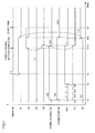
- FIG. 7 is a timing chart illustrating operations of electric power control unit 2 and timer control unit 3 when a problem occurs in a charging system during a period of time from a moment of completion in setting timer charging to charging start time.
- FIG. 8 is a flowchart illustrating a process performed by an instructing unit 73 .
- FIG. 9 is a flowchart illustrating a process performed by electric power control unit 2 .
- FIG. 10 is a flowchart illustrating a notifying process performed by a determining unit 81 and a notifying unit 90 .
- FIG. 11 is a flowchart illustrating another notifying process performed by determining unit 81 and notifying unit 90 .
- a hybrid vehicle is exemplified as an electrically powered vehicle that can be charged by an external power source.
- the electrically powered vehicle that can be charged by an external power source is not limited to a hybrid vehicle and may be, for example, an electric vehicle.
- a vehicle 100 according to the embodiment of the present invention has an internal combustion engine (engine), a power storage device, and a motor driven to rotate by means of electric power supplied from the power storage device. Driving force generated through the internal combustion engine and the motor is distributed optimally, thereby realizing high fuel consumption efficiency.
- the power storage device mounted on vehicle 100 can be charged by electric power from the external power source (as one example, a commercial electric power source).
- FIG. 1 is a side view of vehicle 100 according to the embodiment of the present invention.
- a vehicular main body (body) 300 is provided with a charging inlet 200 .
- Charging inlet 200 is provided with a connector (not shown in FIG. 1 ) connected to a cable that transfers electric power supplied from a commercial electric power source, and a cover 204 for preventing water, dusts, and the like from entering the connector.
- FIG. 1 shows a configuration in which charging inlet 200 is formed adjacent to a front wheel in the left lateral side of vehicular main body 300 . It should be noted that a location in which charging inlet 200 is formed is not particularly limited.
- charging of the power storage device can be started.
- charging of the power storage device can be started at time set in advance. Such charging of the power storage device started at the time set in advance is hereinafter referred to as “timer charging”.
- lamps 211 , 212 are provided in the vicinity of charging inlet 200 .
- lamp 211 illuminates during a period of time from the moment at which the timer charging has been set to the time of starting the charging. This allows the user to confirm that the timer charging has been set correctly. When the present time reaches the charging start time, lamp 211 is put off.
- Lamp 212 illuminates upon the start of the charging of the power storage device, and is put off when the charging ends. Where the timer charging is set, lamp 212 illuminates when the present time reaches the charging start time. This allows the user to confirm that the power storage device is being charged.
- a fuel inlet (not shown) is formed to provide fuel required for operations of the internal combustion engine.
- vehicle 100 Referring to FIG. 2 and FIG. 3 , the configuration of vehicle 100 will be described more in detail below.
- FIG. 2 is a schematic diagram of the configuration of vehicle 100 .
- vehicle 100 is a hybrid vehicle of parallel/series type.
- Vehicle 100 includes: a power storage device (BAT) 4 storing electric power for generating driving force; a charging/discharging device 30 for charging and discharging power storage device 4 ; an electric power control unit 2 for controlling charging/discharging device 30 ; a timer control unit 3 for implementing the timer charging; a lighting device 40 ; a display unit 50 for displaying the start time of the timer charging; an input unit 55 via which a user inputs programmed start time of the timer charging; and switches 61 , 62 .
- BAT power storage device
- Power storage device 4 is an electric power storage element configured to be chargeable and dischargeable.
- Power storage device 4 is constituted by, for example, a secondary battery such as a lithium ion battery or a nickel hydrogen battery, or a power storage element such as an electric double layer capacitor.
- Charging/discharging device 30 includes a converter (CONV) 6 , a main positive bus line MPL, a main negative bus line MNL, a capacitor C, a first inverter (INV 1 ) 8 - 1 , a second inverter (INV 2 ) 8 - 2 , a motor generator MG 1 , and a motor generator MG 2 .
- Converter 6 mutually converts input/output voltage of power storage device 4 into voltage between main positive bus line MPL and main negative bus line MNL.
- the voltage conversion performed by converter 6 is controlled according to a switching command PWC from electric power control unit 2 .
- Capacitor C smoothens voltage between main positive bus line MPL and main negative bus line MNL.
- Inverters 8 - 1 , 8 - 2 are provided so as to correspond to motor generators MG 1 , MG 2 .
- Inverters 8 - 1 , 8 - 2 are electrically connected to power storage device 4 in parallel.
- Each of inverters 8 - 1 , 8 - 2 mutually converts direct-current power into alternating-current power.
- Charging/discharging device 30 further includes a charging connector 25 , an AC port 210 , and power lines Lp, Ln, ACLp, ACLn.
- AC port 210 electrically connects power line Lp and power line ACLp, and electrically connects power line Ln and power line ACLn.
- AC port 210 is connected to charging connector 25 via power lines Lp, Ln.
- AC port 210 is connected to a neutral point N 1 of motor generator MG 1 and a neutral point N 2 of motor generator MG 2 through power lines ACLp and ACLn.
- Each of motor generators MG 1 and MG 2 includes a stator in which a U-phase coil, a V-phase coil, and a W-phase coil form a Y-connection (star connection).
- the Y-connections have points at each of which the three coils are connected. The points correspond to neutral point N 1 of motor generator MG 1 and neutral point N 2 of motor generator MG 2 .
- the charging cable includes power lines PSLp, PSLn, and plugs 260 , 261 .
- Plug 260 is connected to a connector 241 electrically coupled to external power source 240 .
- Plug 261 is connected to charging connector 25 . This allows power lines PSLp, Lp, ACLp to be electrically connected, and allows power lines PSLn, Ln, ACLn to be electrically connected.
- switch 62 When plug 261 is connected to charging connector 25 , switch 62 is turned on.
- Switch 62 is, for example, a mechanical switch having a fixed contact and a movable contact.
- electric power control unit 2 When switch 62 is turned on, electric power control unit 2 is fed with predetermined voltage (ground voltage in the configuration of FIG. 2 ). Accordingly, electric power control unit 2 detects that plug 261 has been brought into connection with charging connector 25 .
- a voltage value and a type (direct current or alternating current) of the electric power supplied from external power source 240 are not particularly limited.
- a commercial electric power source provided at each home can be used as external power source 240 .
- external power source 240 is a commercial electric power source of single-phase alternating current (its voltage value is 100 V or 200 V).
- Control device 262 outputs a signal SAC including information indicating the voltage value of the electric power supplied from external power source 240 , the current capacity thereof, and the like.
- Signal SAC passes through a signal line (not shown) within the charging cable as well as a signal line (not shown) provided between charging connector 25 and electric power control unit 2 , and is delivered to electric power control unit 2 . Based on the information included in signal SAC for example, electric power control unit 2 detects that the electric power is being supplied from external power source 240 .
- the electric power of the external power source is supplied to neutral points N 1 , N 2 of motor generators MG 1 , MG 2 , thereby applying the voltage of power line PSLp to each of the phases in the alternating-current side of inverter 8 - 1 and applying the voltage of power line PSLn to each of the phases of the alternating-current side of inverter 8 - 2 .
- Inverters 8 - 1 , 8 - 2 perform switching operations in response to switching commands PWM 1 , PWM 2 respectively. Accordingly, direct-current power having a predetermined voltage value is supplied from each of inverters 8 - 1 , 8 - 2 to each of main positive bus line MPL and main negative bus line MNL.
- each of inverters 8 - 1 , 8 - 2 has three arm circuits respectively corresponding to the three phases of the alternating-current side.
- Each arm circuit includes an upper arm circuit and a lower arm circuit each having at least one switching element.
- inverters 8 - 1 , 8 - 2 the upper arm circuits respectively corresponding to the phases are collectively turned on/off, and the lower arm circuits respectively corresponding to the phases are also collectively turned on/off. Accordingly, it can be regarded that in each of inverters 8 - 1 , 8 - 2 , the three upper arm circuits are in the same switching state (all of them are on or off). Similarly, it can be regarded that the three lower arm circuits are in the same switching state. Such switching operations render their respective phase voltages equal to one another. In addition, such a switching mode is also referred to as “zero phase mode”.
- FIG. 3 shows a zero phase equivalent circuit of inverters 8 - 1 , 8 - 2 and motor generators MG 1 , MG 2 during the zero phase mode.
- the three upper arm circuits in inverter 8 - 1 can be collectively represented as an upper arm ARM 1 p
- the three lower arm circuits in inverter 8 - 1 are collectively represented as a lower arm ARM 1 n .
- Each of upper arm ARM 1 p and lower arm ARM 1 n is constituted by a switching element TR and a free wheel diode D.
- the three upper arm circuits in inverter 8 - 2 can be collectively represented as an upper arm ARM 2 p
- the three lower arm circuits in inverter 8 - 2 can be collectively represented as a lower arm ARM 2 n.
- the zero phase equivalent circuit shown in FIG. 3 can be regarded as a single-phase inverter that is capable of converting direct-current power, which is supplied through main positive bus line MPL and main negative bus line MNL, into single-phase alternating-current power, and capable of converting single-phase alternating-current power, which is sent to neutral points N 1 and N 2 via power lines ACLp, ACLn, into direct-current power.
- inverters 8 - 1 , 8 - 2 are controlled to realize the zero phase mode, thus allowing inverters 8 - 1 , 8 - 2 to operate equivalently as a single-phase inverter. Accordingly, the single-phase alternating-current power supplied from external power source 240 can be converted into direct-current power, and the direct-current power can be supplied to main positive bus line MPL and main negative bus line MNL. The direct-current power charges power storage device 4 .
- charging/discharging device 30 further includes internal combustion engine ENG and a power splitting mechanism 22 .
- Internal combustion engine ENG operates by means of combustion of fuel.
- Motor generator MG 1 can receive a part of motive power from internal combustion engine ENG to generate electric power.
- Motor generator MG 2 operates as a motor, using electric power from power storage device (BAT) 4 .
- Power splitting mechanism 22 is typically constituted by a planetary gear mechanism.
- charging/discharging device 30 functions as a device that generates driving force for the vehicle.
- inverter 8 - 1 mainly converts alternating-current power generated by motor generator MG 1 , into direct-current power.
- inverter 8 - 2 converts direct-current power supplied via main positive bus line MPL and main negative bus line MNL, into alternating-current power, and supplies the converted alternating-current power to motor generator MG 2 .
- Power splitting mechanism 22 splits in two driving force resulting from operations of internal combustion engine ENG, and distributes a part of it to the motor generator MG 1 side and distributes the rest to motor generator MG 2 .
- the driving force distributed from power splitting mechanism 22 to motor generator MG 1 is used for electric power generating operations. Electric power generated by motor generator MG 1 is used to charge power storage device 4 , and is used for generation of driving force by motor generator MG 2 . The driving force distributed to motor generator MG 2 is combined with driving force generated by motor generator MG 2 , and is used for driving of driving wheel 24 .
- the number of power storage devices and the capacity thereof are not particularly limited.
- a plurality of power storage devices may be mounted on vehicle 100 .
- power storage devices 4 can be sufficiently charged.
- the vehicle can travel using only driving force, generated by motor generator MG 2 , with internal combustion engine ENG maintained at the stop state, i.e., the vehicle achieves EV (Electric Vehicle) traveling.
- EV Electric Vehicle
- the number of power storage devices is increased, more electric power can be stored, thus allowing the vehicle to perform EV traveling for a longer distance.
- Each of electric power control unit 2 and timer control unit 3 is, for example, an ECU (Electronic Control Unit) including a CPU (Central Processing Unit), a RAM (Random Access Memory), a ROM (Read Only Memory), and an input/output interface unit.
- ECU Electronic Control Unit
- CPU Central Processing Unit
- RAM Random Access Memory
- ROM Read Only Memory
- Electric power control unit 2 controls charging/discharging device 30 based on information from current sensors 10 , 14 and voltage sensors 12 , 16 .
- Current sensor 10 detects current Ibat, which is current flowing in power line PL (current sent to/received from power storage device 4 ).
- Voltage sensor 12 detects voltage Vbat between power lines PL, NL.
- Current sensor 14 detects current IDC flowing in main positive bus line MPL.
- Voltage sensor 16 detects voltage VDC between main positive bus line MPL and main negative bus line MNL.
- Electric power control unit 2 receives the values of current Ibat, IDC and the values of voltage Vbat, VDC, and outputs switching commands PWM 1 , PWM 2 , PWC.
- timer control unit 3 instructs electric power control unit 2 to control charging/discharging device 30 .
- Display unit 50 includes a display screen 52 .
- Display screen 52 displays the start time of the timer charging (the start time designated by the user) or the present time.
- Input unit 55 includes operation buttons 56 - 58 .
- operation buttons 56 - 58 When the user presses operation buttons 56 , 57 , the charging start time or present time displayed on display screen 52 is changed.
- operation button 58 When the user presses operation button 58 , the charging start time displayed on display screen 52 is input to timer control unit 3 or the time displayed on display screen 52 is confirmed as the present time.
- switch 61 Connected to timer control unit 3 is switch 61 .
- switch 61 is a mechanical switch.
- timer control unit 3 is fed with predetermined voltage (ground voltage in the configuration of FIG. 2 ). This causes timer control unit 3 to detect that the user has set the timer charging.
- timer control unit 3 sends electric power control unit 2 a signal S 1 indicating that the timer charging has been requested by the user.
- electric power control unit 2 determines whether to permit the timer charging. Then, electric power control unit 2 sends timer control unit 3 a signal S 4 indicating the result of the determination. After sending signal S 4 , electric power control unit 2 is brought into the stand-by state (sleep mode). This reduces electric power consumed by electric power control unit 2 until the start of the charging of power storage device 4 .
- timer control unit 3 If the information included in signal S 4 indicates that electric power control unit 2 has permitted the timer charging, timer control unit 3 outputs a signal S 2 . When the present time reaches the charging start time set by the user, timer control unit 3 outputs a signal S 3 to electric power control unit 2 in order to start up electric power control unit 2 . In response to signal S 3 , electric power control unit 2 operates charging/discharging device 30 to charge power storage device 4 . In addition, electric power control unit 2 outputs a signal S 5 .
- Vehicle 100 further includes a DC/DC converter 20 and an auxiliary battery SB.
- DC/DC converter 20 is electrically connected to power storage device 4 in parallel with converter 6 , DC/DC converter 20 steps down the voltage of electric power discharged from power storage device 4 , to generate auxiliary electric power.
- the voltage of the auxiliary electric power is set lower (for example, 12 V or 24 V) than the charge/discharge voltage of the power storage device (for example, 288 V).
- the auxiliary electric power generated by DC/DC converter 20 is supplied to various auxiliary devices (not shown) of vehicle 100 via a power line DCL. A part of the auxiliary electric power is supplied to an auxiliary battery SB. Auxiliary battery SB stores the auxiliary electric power.
- Auxiliary battery SB allows the auxiliary electric power to be supplied to each of the auxiliary devices even when vehicle 100 is in the resting state (ignition-off state).
- the electric power stored in auxiliary battery SB is supplied to, for example, electric power control unit 2 , timer control unit 3 , and lighting device 40 .
- Auxiliary battery SB is charged by, for example, external power source 240 , as with power storage device 4 .
- power storage device 4 and auxiliary battery SB can be charged by operating DC/DC converter 20 while power storage device 4 is being charged.
- Lighting device 40 includes lamps 211 , 212 , and driving devices 221 , 222 for respectively driving lamps 211 , 212 .
- Each of lamps 211 , 212 is, for example, an LED (light-emitting diode).
- LED light-emitting diode
- the user can readily determine whether or not each of lamps 211 , 212 illuminates. Namely, when the user is away from vehicle 100 , he/she can readily determine the state of power storage device 4 (whether power storage device 4 is being charged, power storage device 4 is before being charged, or the like).
- Lamps 211 , 212 respectively emit, for example, green-colored light and red-colored light. Since lamps 211 , 212 emit light of different colors as such, the user can readily recognize that either lamp 211 or 212 illuminates.
- Driving device 221 drives lamp 211 in response to signal S 2 .
- driving device 222 drives lamp 212 in response to signal S 5 .
- Electric power control unit 2 continues monitoring of charging/discharging device 30 from the moment at which the timer charging has been set (moment at which the startup of charging/discharging device 30 at the charging start time has been set) to the start of the charging. If electric power control unit 2 detects an abnormality in charging/discharging device 30 , electric power control unit 2 sends a signal S 6 to timer control unit 3 in order to cancel the setting of the timer charging.
- timer control unit 3 When receiving signal S 6 , timer control unit 3 cancels the setting of the charging start time. Specifically, timer control unit 3 does not send signal S 3 (start instruction) to electric power control unit 2 even when the present time reaches the charging start time. Electric power control unit 2 never starts the operation of charging/discharging device 30 unless it receives signal S 3 , so charging/discharging device 30 remains stopped.
- the charging system including charging/discharging device 30 , the charging cable, and external power source 240 .
- the charging/discharging device 30 remains stopped. This can reduce adverse effects on the charging system and the vehicle.
- FIG. 4 is a functional block diagram of electric power control unit 2 and timer control unit 3 .
- timer control unit 3 includes a setting unit 71 , a storage unit 72 , and an instructing unit 73 .
- Electric power control unit 2 includes a determining unit 81 , a charging control unit 82 , and a terminating unit 83 .
- determining unit 81 corresponds to an “abnormality monitoring unit” in the present invention.
- Timer control unit 3 and electric power control unit 2 operate using electric power supplied from auxiliary battery SB.
- Determining unit 81 controls a switch 63 that switches to supply electric power to charging control unit 82 and terminating unit 83 and to stop supplying the electric power supply. When switch 63 is turned off, charging control unit 82 and terminating unit 83 are stopped.
- Setting unit 71 sets charging start time.
- an instruction of putting the charging start time forward is sent from input unit 55 to setting unit 71 .
- an instruction of putting the charging start time backward is sent from input unit 55 to setting unit 71 .
- setting unit 71 puts the charging start time backward or forward.
- setting unit 71 sets the charging start time.
- instructing unit 73 acquires information of the charging start time from storage unit 72 .
- Instructing unit 73 transmits to determining unit 81 signal S 3 representing the request for timer charging.
- determining unit 81 determines whether to permit the timer charging. Specifically, determining unit 81 detects whether or not switch 62 is on. If switch 62 is in the on state, it means that the charging cable is connected to the charging connector. Further, determining unit 81 receives signal SAC and determines whether or not alternating-current power has been delivered from external power source 240 to charging connector 25 . Based on the results of the determinations, determining unit 81 sends instructing unit 73 signal S 4 indicating that the timer charging is permitted or not.
- determining unit 81 After transmitting signal S 4 , determining unit 81 turns off switch 63 .
- Instructing unit 73 receives signal S 4 and determines whether or not the timer charging is permitted. If the timer charging is permitted, instructing unit 73 acquires the information of the charging start time from storage unit 72 . Further, instructing unit 73 sends signal S 2 to driving device 221 . In response to signal S 2 , driving device 221 causes lamp 211 to illuminate.
- instructing unit 73 transmits signal S 3 to determining unit 81 .
- determining unit 81 turns on switch 63 .
- This starts up charging control unit 82 and terminating unit 83 .
- charging control unit 82 and terminating unit 83 are stopped. Hence, during this period, electric power consumption of electric power control unit 2 can be reduced.
- instructing unit 73 causes driving device 221 to stop the operation of lamp 211 .
- charging control unit 82 When electric power is supplied from auxiliary battery SB, charging control unit 82 starts charging/discharging device 30 . In addition, charging control unit 82 sends signal S 5 to driving device 222 . In response to signal S 5 , driving device 222 causes lamp 212 to illuminate.
- charging control unit 82 calculates a value indicating a state of charge of power storage device 4 , and outputs the value thereof to terminating unit 83 . Based on the value indicating the state of charge of power storage device 4 , terminating unit 83 determines whether or not a charging end condition of power storage device 4 is satisfied. When the charging end condition is satisfied, terminating unit 83 instructs charging control unit 82 to end the operation of charging/discharging device 30 . In response to the instruction from terminating unit 83 , charging control unit 82 stops charging/discharging device 30 , and causes driving device 222 to stop the operation of lamp 212 .
- Terminating unit 83 may calculate, based on current Ibat and voltage Vbat, the value indicating the state of charge of power storage device 4 , and may determine based on the value whether or not the charging end condition of power storage device 4 is satisfied.
- determining unit 81 determines that there has occurred an abnormality in the charging system (detects an abnormality), it sends signal S 6 to instructing unit 73 .
- instructing unit 73 cancels the setting of the charging start time.
- determining unit 81 turns on a flag FLG stored therein, and sends an instruction to a notifying unit 90 to notify the user of the abnormality in the charging system.
- notifying unit 90 performs a process to notify the user of the abnormality in the charging system.
- Notifying unit 90 may be a device that lights up a display light representing an abnormality in the charging system, or may be a device that emits a sound to notify the user of an abnormality in the charging system.
- Determining unit 81 is always supplied with electric power from auxiliary battery SB. Therefore, once flag FLG is turned on, it is maintained at the on state. This allows determining unit 81 to send an instruction to notifying unit 90 at any timing.
- a flow of the timer charging process will be described with reference to FIG. 5 and FIG. 6 . It should be noted that the description below assumes that when a signal is at the H (logic high) level, its logic is enabled. In addition, a state in which a signal is switched from the L (logic low) level to the H level corresponds to a state at which the signal is transmitted.
- FIG. 5 is a first timing chart illustrating operations of electric power control unit 2 and timer control unit 3 .
- FIG. 5 shows a flow of the timer charging process performed when the charging cable is first connected to the charging connector and then the user presses switch 61 .
- switch 62 connector SW
- determining unit 81 turns on switch 63 (power source SW).
- the electric power stored in auxiliary battery SB is supplied to charging control unit 82 , thus starting up charging control unit 82 .
- determining unit 81 receives signal SAC for every fixed time and determines a state of supply of electric power from external power source 240 .
- FIG. 5 shows a state in which duration of signal SAC is short and signal SAC is repeatedly generated. Namely, FIG. 5 shows a state in which determining unit 81 receives signal SAC for every fixed time.
- determining unit 81 When determining unit 81 determines that the supply of electric power from external power source 240 is normal (for example, external power source 240 is not in failure), it sends, at time t 2 , an instruction to charging control unit 82 in order to start up charging/discharging device 30 .
- Charging control unit 82 receives the instruction, and starts to control charging/discharging device 30 . In this way, charging of power storage device 4 is started.
- Charging control unit 82 repeatedly varies signal S 5 until it receives the instruction for starting up charging/discharging device 30 . This causes lamp 212 to blink.
- charging control unit 82 changes the level of signal S 5 from the L level to the H level. This causes lamp 212 to illuminate.
- determining unit 81 changes the level of signal S 4 from the L level to the H level.
- instructing unit 73 changes the level of signal S 2 from the L level to the H level.
- driving device 221 causes lamp 211 to illuminate.
- determining unit 81 turns off switch 63 (power source SW). This interrupts the supply of electric power from auxiliary battery SB to charging control unit 82 , thereby stopping charging control unit 82 .
- the charging of power storage device 4 is once terminated and lamp 212 is put out.
- determining unit 81 monitors for presence/absence of an abnormality in the charging system. As long as the charging system is normal, the level of signal S 6 is kept at the L level.
- Time t 6 corresponds to the charging start time set by the user.
- instructing unit 73 changes the level of signal S 3 from the L level to the H level.
- determining unit 81 turns on switch 63 (power source SW). Accordingly, the electric power stored in auxiliary battery SB is supplied to charging control unit 82 , thus starting up charging control unit 82 .
- charging control unit 82 performs a process similar to the process performed during the period of time from time t 1 to time t 2 .
- charging control unit 82 resumes the charging of power storage device 4 and sets the level of signal S 5 at the H level.
- driving device 222 causes lamp 212 to illuminate.
- FIG. 6 is a second timing chart illustrating operations of electric power control unit 2 and timer control unit 3 .
- FIG. 6 shows a flow of the timer charging process performed when the user first presses switch 61 and the charging cable is then connected to the charging connector.
- switch 62 (connector SW) is turned on. Namely, the charging cable is connected to charging connector 25 .
- determining unit 81 turns on switch 63 (power source SW). Accordingly, the electric power stored in auxiliary battery SB is supplied to charging control unit 82 , thus starting up charging control unit 82 .
- Determining unit 81 receives signal SAC, determines a state of supply of electric power from external power source 240 , and determines whether or not the timer charging can be permitted. When determining unit 81 determines that the supply of electric power from external power source 240 is normal (for example, external power source 240 is not in failure), it sends, at time t 13 , an instruction to charging control unit 82 in order to start up charging/discharging device 30 . In response to the instruction, charging control unit 82 starts to control charging/discharging device 30 . In this way, charging of power storage device 4 is started.
- Charging control unit 82 repeatedly varies signal 85 during a period of time from time t 12 to time t 13 . This causes lamp 212 to blink. After time t 13 , charging control unit 82 maintains the level of signal S 5 at the H level. Accordingly, lamp 212 illuminates continuously.
- determining unit 81 changes the level of signal S 4 from the L level to the H level. Processes performed by electric power control unit 2 and timer control unit 3 after time t 14 are similar to the processes performed by electric power control unit 2 and timer control unit 3 after time t 4 , so explanation therefor is not repeated.
- FIG. 7 is a timing chart illustrating operations performed by electric power control unit 2 and timer control unit 3 when an abnormality occurs in the charging system during a period of time from the moment of completion in setting the timer charging to the charging start time.
- FIG. 7 operations of electric power control unit 2 and timer control unit 3 before time t 5 are similar to those of electric power control unit 2 and timer control unit 3 shown in FIG. 5 .
- FIG. 7 illustrates decoupling of the charging cable from the charging connector.
- switch 62 (connector SW) becomes off at time t 5 A.
- determining unit 81 detects that switch 62 has become off and changes the level of signal 56 from the L level to the H level.
- instructing unit 73 changes each of the levels of signals S 1 , S 2 from the H level to the L level.
- Signal S 1 at the L level represents that timer control unit 3 has canceled the request for the timer charging.
- signal 52 at the L level causes lamp 211 to be put out.
- instructing unit 73 maintains the level of signal S 3 at the L level. Namely, instructing unit 73 stops transmission of signal S 3 .
- determining unit 81 does not turn on switch 63 (power source SW). Accordingly, charging control unit 82 is not started up, so charging/discharging device 30 remains stopped. Thus, the power storage device is not charged.
- FIG. 8 is a flowchart illustrating a process performed by instructing unit 73 .
- the process in the flowchart is called from a main routine and executed whenever a fixed period of time passes or a predetermined condition is satisfied.
- instructing unit 73 determines whether or not switch 61 has become on (step ST 1 ). When switch 61 is in the off state (NO in step ST 1 ), the process by instructing unit 73 is ended. When switch 61 has become on (YES in step ST 1 ), instructing unit 73 outputs a timer charging request (signal S 1 ) to determining unit 81 .
- Instructing unit 73 receives signal S 4 which indicates the result of the determination as to permission for the charging by electric power control unit 2 (step ST 3 ). Instructing unit 73 determines whether or not electric power control unit 2 has permitted the timer charging (step ST 4 ). If the timer charging is not permitted (NO in step ST 4 ), the process by instructing unit 73 is ended. If the timer charging is permitted (YES in step ST 4 ), instructing unit 73 reads out the programmed start time recorded in storage unit 72 so as to set the charging start time (step ST 5 ).
- instructing unit 73 transmits signal 52 shown in FIG. 6 to driving device 221 so as to cause lamp 211 to illuminate (step ST 6 ).
- instructing unit 73 determines whether or not signal S 6 has been received (step ST 7 ). If signal S 6 has not been received (NO in step ST 7 ), instructing unit 73 performs a process of step ST 8 .
- step ST 8 instructing unit 73 determines whether or not the present time has reached the charging start time. If the present time has not reached the charging start time (NO in step ST 8 ), the process goes back to step ST 6 . If the present time has reached the charging start time (YES in step ST 8 ), instructing unit 73 transmits signal S 3 to electric power control unit 2 (determining unit 81 ) to start up electric power control unit 2 (step ST 9 ). Further, instructing unit 73 causes driving device 221 to put out lamp 211 (step ST 10 ).
- instructing unit 73 performs a process of step ST 11 .
- instructing unit 73 cancels the setting of the charging start time. Then, instructing unit 73 causes driving device 221 to put out lamp 211 (step ST 10 ).
- step ST 10 When the process in step ST 10 is ended, the entire process by instructing unit 73 is terminated.
- FIG. 9 is a flowchart illustrating a process performed by electric power control unit 2 .
- the process in the flowchart is called from the main routine and executed whenever a fixed period of time passes or a predetermined condition is satisfied.
- determining unit 81 determines whether or not the charging is permitted (step ST 21 ). Specifically, determining unit 81 determines whether or not switch 62 is in the on state. Further, determining unit 81 receives signal SAC and determines whether or not alternating-current power has been delivered from external power source 240 to charging connector 25 . If switch 62 is in the on state and the alternating-current power has been delivered from external power source 240 to charging connector 25 , determining unit 81 transmits signal S 4 indicating that the timer charging is permitted, to timer control unit 3 (instructing unit 73 ) (step ST 22 ).
- determining unit 81 After transmitting signal S 4 , determining unit 81 turns off switch 63 . This stops supply of electric power to charging control unit 82 and terminating unit 83 . Determining unit 81 monitors for an abnormality in the charging system (step ST 23 ). Specifically, for example, determining unit 81 checks, for every fixed period of time and in accordance with signal SAC, whether or not the external power source is in failure, or checks, based on a state of switch 62 , whether or not the charging cable is decoupled from charging connector 25 .
- determining unit 81 determines whether or not there is a problem in the charging system (step ST 24 ). If determining unit 81 determines that there is an abnormality in the charging system (YES in step ST 24 ), it turns on a flag stored therein (step ST 31 ). In addition, determining unit 81 transmits signal S 6 (step ST 32 ). When the process in step ST 32 is ended, the entire process is terminated.
- step ST 24 determines whether or not signal S 3 has been received (step ST 25 ). If determining unit 81 has not received signal S 3 (NO in step ST 25 ), the process goes back to step ST 23 . If determining unit 81 has received signal S 3 (YES in step ST 25 ), the process goes to step ST 26 .
- step ST 26 determining unit 81 turns on switch 63 . Accordingly, the electric power stored in auxiliary battery SB is supplied to charging control unit 82 and terminating unit 83 . Further, determining unit 81 instructs charging control unit 82 to start charging. Charging control unit 82 starts to control charging/discharging device 30 . In this way, the charging of the power storage device is started (step ST 26 ).
- charging control unit 82 transmits signal S 5 to driving device 222 so as to light up lamp 212 (step ST 27 ).
- terminating unit 83 determines whether or not the charging end condition of the power storage device has been satisfied (step ST 28 ). For example, charging control unit 82 calculates a value of a state of charge of the power storage device. When the value reaches a predetermined value (for example, 80%), terminating unit 83 determines that the charging end condition has been satisfied.
- a predetermined value for example, 80%
- step ST 28 If the charging end condition is not satisfied (NO in step ST 28 ), the process of step ST 28 is repeated. On the other hand, if the charging end condition is satisfied (YES in step ST 28 ), terminating unit 83 sends an instruction to charging control unit 82 so as to end the charging. Upon receiving the instruction, charging control unit 82 stops charging/discharging device 30 . In this way, the charging of the power storage device is ended (step ST 29 ). In addition, charging control unit 82 puts out lamp 212 (step ST 30 ). When the process in step ST 30 is ended, the entire process is terminated.
- FIG. 10 is a flowchart illustrating a notifying process performed by determining unit 81 and notifying unit 90 .
- determining unit 81 determines whether or not the flag is on (step ST 41 ). If the flag is not on (NO in step ST 41 ), the entire process is terminated. If the flag is on (YES in step ST 41 ), determining unit 81 sends an instruction to notifying unit 90 . Upon receiving the instruction, notifying unit 90 performs a process to notify the user of occurrence of an abnormality (step ST 42 ).
- the process in the flowchart of FIG. 10 is called from the main routine and executed whenever a fixed period of time passes from the moment of completion in setting the timer charging. Accordingly, when an abnormality occurs in the charging system, notification can be made in a short time from the moment of occurrence of the abnormality. Accordingly, the user can be notified of the abnormality in the charging system quickly.
- FIG. 11 A flowchart of FIG. 11 is different from that of FIG. 10 in that a process of step ST 41 A is added.
- determining unit 81 determines whether or not a signal IGON (see FIG. 4 ) representing an instruction for starting vehicle 100 has been received (step ST 41 A). It should be noted that signal IGON is sent from the external ECU to determining unit 81 when the user instructs the vehicle to start (for example, the user turns on a switch for starting the vehicle).
- step ST 41 A If determining unit 81 has not received signal IGON (NO in step ST 41 A), the entire process is terminated. If determining unit 81 has received signal IGON (YES in step ST 41 A), it performs the process of step ST 41 (determines whether or not flag FLG is on). The processes after step ST 41 are similar to those in the flowchart of FIG. 10 .
- signal IGON is input to determining unit 81 by the user when he/she operates to start the vehicle.
- the user can know occurrence of a problem in the charging system more securely.
- the determining unit is included in the electric power control unit.
- the determining unit may be included in the timer control unit.
- the timer control unit and the electric power control unit may be integrated.
- FIG. 2 shows the series/parallel type hybrid system in which motive power of the engine can be split for the axle and the electric power generator by the power splitting mechanism and can be transmitted thereto.
- the present invention is applicable to a parallel type hybrid vehicle and a series type hybrid vehicle.
- charging start time (programmed start time).
- the user may input programmed end time to setting unit 71 .
- setting unit 71 sets, for example, charging start time at time coming before the programmed end time by a predetermined period of time. It should be noted that a way in which setting unit 71 sets the charging start time based on the programmed end time is not limited to this.
- the configuration for externally charging power storage device 4 is not limited to the configuration of each of FIG. 2 and FIG. 3 .
- a rectifier device and an inverter device may be provided outside the vehicle to convert the alternating-current power into direct-current power.
- the power storage device can be directly charged by the direct-current power supplied from outside the vehicle.
Applications Claiming Priority (3)
| Application Number | Priority Date | Filing Date | Title |
|---|---|---|---|
| JP2007-226071 | 2007-08-31 | ||
| JP2007226071A JP4306775B2 (ja) | 2007-08-31 | 2007-08-31 | 電動車両 |
| PCT/JP2008/064958 WO2009028400A1 (ja) | 2007-08-31 | 2008-08-15 | 電動車両 |
Publications (2)
| Publication Number | Publication Date |
|---|---|
| US20100204859A1 US20100204859A1 (en) | 2010-08-12 |
| US8326476B2 true US8326476B2 (en) | 2012-12-04 |
Family
ID=40387122
Family Applications (1)
| Application Number | Title | Priority Date | Filing Date |
|---|---|---|---|
| US12/669,747 Active 2030-01-28 US8326476B2 (en) | 2007-08-31 | 2008-08-15 | Electrically powered vehicle |
Country Status (5)
| Country | Link |
|---|---|
| US (1) | US8326476B2 (de) |
| EP (1) | EP2190098B1 (de) |
| JP (1) | JP4306775B2 (de) |
| CN (1) | CN101849339B (de) |
| WO (1) | WO2009028400A1 (de) |
Cited By (2)
| Publication number | Priority date | Publication date | Assignee | Title |
|---|---|---|---|---|
| US20140002091A1 (en) * | 2011-03-22 | 2014-01-02 | Hitachi Construction Machinery Co., Ltd. | Construction machine |
| US11952930B2 (en) * | 2018-10-31 | 2024-04-09 | Cummins Inc. | Inverter-based exhaust aftertreatment thermal management apparatuses, methods, systems, and techniques |
Families Citing this family (21)
| Publication number | Priority date | Publication date | Assignee | Title |
|---|---|---|---|---|
| JP2010154646A (ja) * | 2008-12-25 | 2010-07-08 | Omron Corp | 充電制御装置および方法、並びに、プログラム |
| WO2010122647A1 (ja) * | 2009-04-23 | 2010-10-28 | トヨタ自動車株式会社 | 車両、充電ケーブルおよび車両の充電システム |
| WO2010150360A1 (ja) * | 2009-06-24 | 2010-12-29 | トヨタ自動車株式会社 | 電動車両の充電制御装置 |
| FR2953953B1 (fr) * | 2009-12-15 | 2016-07-01 | Renault Sa | Procede de fonctionnement d'une architecture electrique d'un vehicule automobile electrique |
| JP5171974B2 (ja) | 2010-02-19 | 2013-03-27 | ヤマハ発動機株式会社 | 電動二輪車 |
| DE102010062116A1 (de) * | 2010-11-29 | 2012-05-31 | Bayerische Motoren Werke Aktiengesellschaft | Energiespeichervorrichtung für ein Kraftfahrzeug |
| JP5375849B2 (ja) * | 2011-02-10 | 2013-12-25 | 株式会社デンソー | 車両用充電制御装置、および、車両用充電制御システム |
| US9013319B2 (en) | 2011-08-23 | 2015-04-21 | Lear Corporation | Vehicle inlet for use in charging a battery of an electric vehicle (EV) or a hybrid electric vehicle (HEV) |
| JP5710440B2 (ja) * | 2011-10-06 | 2015-04-30 | トヨタ自動車株式会社 | 車両の充電システムおよび車両の充電方法 |
| JP2013090549A (ja) * | 2011-10-21 | 2013-05-13 | Denso Corp | 車載充電制御システム |
| US9358896B2 (en) | 2011-12-27 | 2016-06-07 | Mitsubishi Electric Corporation | Energy management system |
| CN104040822B (zh) * | 2012-01-06 | 2016-12-07 | 株式会社日立制作所 | 电网稳定化系统及电网稳定化方法 |
| US9365115B2 (en) * | 2012-01-20 | 2016-06-14 | Ford Global Technologies, Llc | System and method for vehicle power management |
| EP2645467A1 (de) * | 2012-03-26 | 2013-10-02 | Samsung SDI Co., Ltd. | Batteriepackladesystem und Steuerverfahren dafür |
| JP5910524B2 (ja) * | 2013-01-29 | 2016-04-27 | 株式会社豊田自動織機 | 過電流停止回路、過電流停止方法および給電装置 |
| JP5772862B2 (ja) | 2013-04-10 | 2015-09-02 | 株式会社デンソー | 充電制御装置 |
| JP5937542B2 (ja) * | 2013-05-15 | 2016-06-22 | 株式会社城南製作所 | 車両用カバー開閉制御装置 |
| KR101610482B1 (ko) * | 2014-07-28 | 2016-04-07 | 현대자동차주식회사 | 전기차의 충전 예약 취소 및 즉시 충전을 위한 방법 및 장치 |
| CN106114269B (zh) * | 2016-08-05 | 2018-07-17 | 华霆(合肥)动力技术有限公司 | 电动车充电控制方法和装置 |
| CN106274498A (zh) * | 2016-08-30 | 2017-01-04 | 奇瑞商用车(安徽)有限公司 | 电动汽车电池管理系统的控制方法 |
| JP6888034B2 (ja) * | 2019-01-24 | 2021-06-16 | 本田技研工業株式会社 | 充電管理装置、および、プログラム |
Citations (18)
| Publication number | Priority date | Publication date | Assignee | Title |
|---|---|---|---|---|
| JPH06343202A (ja) | 1993-06-01 | 1994-12-13 | Nissan Motor Co Ltd | 電気自動車の充電装置 |
| JPH06343204A (ja) | 1993-06-01 | 1994-12-13 | Nissan Motor Co Ltd | 電気自動車の充電装置 |
| JPH0746768A (ja) | 1993-07-27 | 1995-02-14 | Toyota Motor Corp | 車載充電器の表示装置 |
| JPH07107618A (ja) | 1993-09-29 | 1995-04-21 | Kojima Press Co Ltd | 電気自動車用バッテリーの充電装置 |
| JPH07123599A (ja) | 1993-10-18 | 1995-05-12 | Toyota Motor Corp | 充電制御装置 |
| JPH08336236A (ja) | 1995-06-06 | 1996-12-17 | Honda Motor Co Ltd | 電気自動車用蓄電池充電制御装置 |
| DE29707965U1 (de) | 1997-05-02 | 1997-07-10 | Opel Adam Ag | Kraftfahrzeug mit Elektro-Fahrantrieb |
| US5650710A (en) | 1995-02-06 | 1997-07-22 | Honda Giken Kogyo Kabushiki Kaisha | Apparatus for controlling a charging start time and charging period for a storage battery in an electric vehicle to complete charging at a scheduled boarding time |
| JPH09233720A (ja) | 1996-02-20 | 1997-09-05 | Sumitomo Electric Ind Ltd | 充電コントローラ |
| JPH11122825A (ja) | 1997-10-13 | 1999-04-30 | Denso Corp | バッテリの充電装置 |
| EP1220350A1 (de) | 1999-09-07 | 2002-07-03 | Tokyo R & D Co., Ltd. | Elektrische vorrichtung mit zeitgeber |
| US20070278990A1 (en) * | 2006-06-06 | 2007-12-06 | Spx Corporation | Battery boosting apparatus and method |
| US20100131137A1 (en) * | 2007-06-15 | 2010-05-27 | Toyota Jidosha Kabushiki Kaisha | Power supply system, vehicle with the same and charge/discharge control method |
| US20110264319A1 (en) * | 2009-08-18 | 2011-10-27 | Ford Global Technologies, Llc | Plug-In Vehicle |
| US8091663B2 (en) * | 2008-05-12 | 2012-01-10 | Toyota Jidosha Kabushiki Kaisha | Hybrid vehicle and method of controlling the same |
| US20120016547A1 (en) * | 2009-03-05 | 2012-01-19 | Toyota Jidosha Kabushiki Kaisha | Charging/discharging control system for hybrid vehicle and method for controlling same |
| US20120062168A1 (en) * | 2010-09-10 | 2012-03-15 | Panasonic Electric Works Co., Ltd. | Charging control device |
| US20120109443A1 (en) * | 2009-07-01 | 2012-05-03 | Toyota Jidosha Kabushiki Kaisha | Control system of vehicle |
-
2007
- 2007-08-31 JP JP2007226071A patent/JP4306775B2/ja active Active
-
2008
- 2008-08-15 CN CN2008801043257A patent/CN101849339B/zh not_active Expired - Fee Related
- 2008-08-15 US US12/669,747 patent/US8326476B2/en active Active
- 2008-08-15 WO PCT/JP2008/064958 patent/WO2009028400A1/ja active Application Filing
- 2008-08-15 EP EP08792629A patent/EP2190098B1/de not_active Not-in-force
Patent Citations (19)
| Publication number | Priority date | Publication date | Assignee | Title |
|---|---|---|---|---|
| JPH06343204A (ja) | 1993-06-01 | 1994-12-13 | Nissan Motor Co Ltd | 電気自動車の充電装置 |
| JPH06343202A (ja) | 1993-06-01 | 1994-12-13 | Nissan Motor Co Ltd | 電気自動車の充電装置 |
| JPH0746768A (ja) | 1993-07-27 | 1995-02-14 | Toyota Motor Corp | 車載充電器の表示装置 |
| JPH07107618A (ja) | 1993-09-29 | 1995-04-21 | Kojima Press Co Ltd | 電気自動車用バッテリーの充電装置 |
| JPH07123599A (ja) | 1993-10-18 | 1995-05-12 | Toyota Motor Corp | 充電制御装置 |
| US5650710A (en) | 1995-02-06 | 1997-07-22 | Honda Giken Kogyo Kabushiki Kaisha | Apparatus for controlling a charging start time and charging period for a storage battery in an electric vehicle to complete charging at a scheduled boarding time |
| JPH08336236A (ja) | 1995-06-06 | 1996-12-17 | Honda Motor Co Ltd | 電気自動車用蓄電池充電制御装置 |
| JPH09233720A (ja) | 1996-02-20 | 1997-09-05 | Sumitomo Electric Ind Ltd | 充電コントローラ |
| DE29707965U1 (de) | 1997-05-02 | 1997-07-10 | Opel Adam Ag | Kraftfahrzeug mit Elektro-Fahrantrieb |
| JPH11122825A (ja) | 1997-10-13 | 1999-04-30 | Denso Corp | バッテリの充電装置 |
| EP1220350A1 (de) | 1999-09-07 | 2002-07-03 | Tokyo R & D Co., Ltd. | Elektrische vorrichtung mit zeitgeber |
| US20070278990A1 (en) * | 2006-06-06 | 2007-12-06 | Spx Corporation | Battery boosting apparatus and method |
| US20100131137A1 (en) * | 2007-06-15 | 2010-05-27 | Toyota Jidosha Kabushiki Kaisha | Power supply system, vehicle with the same and charge/discharge control method |
| US8091663B2 (en) * | 2008-05-12 | 2012-01-10 | Toyota Jidosha Kabushiki Kaisha | Hybrid vehicle and method of controlling the same |
| US20120016547A1 (en) * | 2009-03-05 | 2012-01-19 | Toyota Jidosha Kabushiki Kaisha | Charging/discharging control system for hybrid vehicle and method for controlling same |
| US8229616B2 (en) * | 2009-03-05 | 2012-07-24 | Toyota Jidosha Kabushiki Kaisha | Charging/discharging control system for hybrid vehicle and method for controlling same |
| US20120109443A1 (en) * | 2009-07-01 | 2012-05-03 | Toyota Jidosha Kabushiki Kaisha | Control system of vehicle |
| US20110264319A1 (en) * | 2009-08-18 | 2011-10-27 | Ford Global Technologies, Llc | Plug-In Vehicle |
| US20120062168A1 (en) * | 2010-09-10 | 2012-03-15 | Panasonic Electric Works Co., Ltd. | Charging control device |
Non-Patent Citations (2)
| Title |
|---|
| Extended European Search Report issued in European Application No. EP 08 79 2629 dated Jun. 24, 2011. |
| International Search Report issued in International Application No. PCT/JP2008/064958; Mailed Oct. 21, 2008 (with translation). |
Cited By (2)
| Publication number | Priority date | Publication date | Assignee | Title |
|---|---|---|---|---|
| US20140002091A1 (en) * | 2011-03-22 | 2014-01-02 | Hitachi Construction Machinery Co., Ltd. | Construction machine |
| US11952930B2 (en) * | 2018-10-31 | 2024-04-09 | Cummins Inc. | Inverter-based exhaust aftertreatment thermal management apparatuses, methods, systems, and techniques |
Also Published As
| Publication number | Publication date |
|---|---|
| WO2009028400A1 (ja) | 2009-03-05 |
| US20100204859A1 (en) | 2010-08-12 |
| EP2190098A4 (de) | 2011-07-06 |
| EP2190098A1 (de) | 2010-05-26 |
| JP2009060728A (ja) | 2009-03-19 |
| JP4306775B2 (ja) | 2009-08-05 |
| EP2190098B1 (de) | 2013-03-06 |
| CN101849339B (zh) | 2013-02-06 |
| CN101849339A (zh) | 2010-09-29 |
Similar Documents
| Publication | Publication Date | Title |
|---|---|---|
| US8326476B2 (en) | Electrically powered vehicle | |
| JP5293841B2 (ja) | 電動車両の電源システムおよびその制御方法 | |
| US8810060B2 (en) | Charging device for vehicle | |
| US9614399B2 (en) | Charging control device using in-vehicle solar cell | |
| US9013142B2 (en) | Charging connector and charging cable unit | |
| US8179086B2 (en) | Control apparatus and control method | |
| JP4375472B2 (ja) | 車両の充電制御装置 | |
| EP2641771B1 (de) | Aufladevorrichtung für fahrzeuge | |
| US7791217B2 (en) | Electric-powered vehicle chargeable by external power supply | |
| JP4816628B2 (ja) | 車両の充電制御装置 | |
| US8476865B2 (en) | Control device and method for charge control | |
| CN105917548B (zh) | 采用通过充电电缆从外部电源提供的电力来充电的车辆 | |
| JP5201273B2 (ja) | 電源管理装置 | |
| WO2012049559A2 (en) | Electromotive vehicle | |
| JP2010283944A (ja) | プラグイン車両の制御装置及び制御方法 | |
| CN104584373A (zh) | 车辆电力控制系统和电力控制方法 | |
| JP4930289B2 (ja) | 電動車両 | |
| JP2010166760A (ja) | 電源システム |
Legal Events
| Date | Code | Title | Description |
|---|---|---|---|
| AS | Assignment |
Owner name: TOYOTA JIDOSHA KABUSHIKI KAISHA, JAPAN Free format text: ASSIGNMENT OF ASSIGNORS INTEREST;ASSIGNOR:KAMAGA, RYUICHI;REEL/FRAME:023813/0848 Effective date: 20091106 |
|
| STCF | Information on status: patent grant |
Free format text: PATENTED CASE |
|
| FEPP | Fee payment procedure |
Free format text: PAYOR NUMBER ASSIGNED (ORIGINAL EVENT CODE: ASPN); ENTITY STATUS OF PATENT OWNER: LARGE ENTITY |
|
| FPAY | Fee payment |
Year of fee payment: 4 |
|
| MAFP | Maintenance fee payment |
Free format text: PAYMENT OF MAINTENANCE FEE, 8TH YEAR, LARGE ENTITY (ORIGINAL EVENT CODE: M1552); ENTITY STATUS OF PATENT OWNER: LARGE ENTITY Year of fee payment: 8 |