US821237A - Bag-holder. - Google Patents
Bag-holder. Download PDFInfo
- Publication number
- US821237A US821237A US26712705A US1905267127A US821237A US 821237 A US821237 A US 821237A US 26712705 A US26712705 A US 26712705A US 1905267127 A US1905267127 A US 1905267127A US 821237 A US821237 A US 821237A
- Authority
- US
- United States
- Prior art keywords
- bag
- holder
- holders
- support
- clamp
- Prior art date
- Legal status (The legal status is an assumption and is not a legal conclusion. Google has not performed a legal analysis and makes no representation as to the accuracy of the status listed.)
- Expired - Lifetime
Links
- 241000239290 Araneae Species 0.000 description 5
- 238000010276 construction Methods 0.000 description 5
- 239000002184 metal Substances 0.000 description 4
- 238000005452 bending Methods 0.000 description 3
- NJPPVKZQTLUDBO-UHFFFAOYSA-N novaluron Chemical compound C1=C(Cl)C(OC(F)(F)C(OC(F)(F)F)F)=CC=C1NC(=O)NC(=O)C1=C(F)C=CC=C1F NJPPVKZQTLUDBO-UHFFFAOYSA-N 0.000 description 3
- 230000000717 retained effect Effects 0.000 description 2
- 101150111878 Vegfd gene Proteins 0.000 description 1
- 230000032683 aging Effects 0.000 description 1
- 238000005266 casting Methods 0.000 description 1
- 238000004519 manufacturing process Methods 0.000 description 1
Images

Classifications
-
- A—HUMAN NECESSITIES
- A47—FURNITURE; DOMESTIC ARTICLES OR APPLIANCES; COFFEE MILLS; SPICE MILLS; SUCTION CLEANERS IN GENERAL
- A47F—SPECIAL FURNITURE, FITTINGS, OR ACCESSORIES FOR SHOPS, STOREHOUSES, BARS, RESTAURANTS OR THE LIKE; PAYING COUNTERS
- A47F5/00—Show stands, hangers, or shelves characterised by their constructional features
- A47F5/0006—Hangers for hanging articles on bars, tringles, bracket arms or the like
Definitions
- My invention relates to improvements in holders for paper bags and the like.
- the object of the invention is to provide a device of this character which will be simple in construction, durable in use, efficient in operation, and comparatively-inexpensive to manufacture. 1
- the invention consists of certain novel features of construction, combination, and arrangement of parts, as will be hereinafter described and claimed.
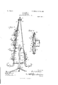
- Figure 1 is a perspective view of a series of my improved bag-holders mounted upon a pedestal.
- Fig. 2 is a vertical sectional view through the same.
- Fig. 3 is a detail horizontal sectional view; and
- Fig. 4 is a perspective view of one of the bag-holders removed from its su port.
- numera 1 denotes one of my improved bag-holders, which comprises a frame 2, constructed, preferably, of a single piece of metal rod or wire.
- This frame 2 is formed at its lower end with a bagsupporting hook 3 which is formed by bending the piece of wire or rod from which the frame 2 is formed upon itself at its center, as clearly shown in the drawings.
- the paper bags B are adapted to rest upon the portions 4 of said hook and are retained thereon by the upwardly-projecting portion 5 of the same.
- the body portions 6 of the hook which extend parallel to each other, are bent outwardly, as shown at 7, and then upwardly to form two parallel arms 8, which are attached to a suitable support 9.
- a back plate 10 against which the bags are adapted to rest.
- a transversely-extending projection 1 1 which is preferably in the form of a roll or cylinder.
- the bags B are placed above this roll 11, which is adaptedto hold their intermediate portions extended, as shown in Figf 1 of the drawings.
- the upper portions of the bags are retained upon the back plate 10 by a swinging clamp 12, which is preferably of U form and constructed from a single piece of metal rod or wire.
- One end or arm 13 of the clamp 12 extends through the roll 11 and is mounted in suitable bearings, as shown, and
- the bag-holders above described may be mounted singly or in groups or series upon any desired support and may be constructed in different sizes to accommodate bags of different sizes.
- Figs. 1 and 2 of the drawin s 1 have shown a pedestal 18, consisting of a ase 19, supported upon legs and having projecting vertically from its center an upright or standard 20 upon which two or more spiders 21 may be mounted, as desired.
- the spiders 21 are mounted two sets of the bag-holding devices 1, the set upon one side consisting of three of said holders and the set upon the opposite side consisting of one; but it will be understood that any desired number may be provided.
- the largest and lowermost holder of each set has its arms 8 secured in apertures in the spiders 21, and to their upper ends is attached by longitudinallyextending bolts or the like 22 the support 9.
- the latter is here shown in the form of a casting consisting of two parts which are riveted or otherwise secured together; but it will be understood that the same may be of any other form and construction.
- the upper ends of the arms 8 of each of the remaining bag-holders are formed with eyes through which the bolts 22 pass, as clearly shown in Fig 2 of the drawings, so that said holders are pivotally mounted.
- I oted maybe suspended by suspending the l swinging the free end of said clamp to said support 9.
- the herein-described bag-holder com prising a pedestal, spiders mounted thereon, bag-supporting frames having upwardly-extending arms secured to the spiders, supporting lower portions 4 and outwardly-extending portions 5, plates connecting the arms of the said frames, rolls on the outer, lower portions of said plates, spring-actuated clamps pivoted in said rolls, and a support 9 to which the upper ends of the bag-supporting frames are secured.
- a bag-holder comprising a frame having'a hook-shaped support at its lower end, a plate upon said frame, a transversely-extending projection or enlargement upon said plate above said support, a swinging clamp pivplate, substantially as described] 3.
- Abag-holder comprisin a frameformed by bending a piece of meta rod or wire to form a supporting-hook, a plate connecting the sides of the frame, a transversely-extending roll upon said plate, a spring-actuated clamp pivoted in said roll, and means for supporting said frame, substantially as described.
- a bag-holder comprising a frame formed by bending a piece of metal rod or wire to form a supporting-hook, a plate connecting the sides of the frame, a transversely-eX- tending roll upon said plate, a substantially U-shaped clamp pivoted in said roll and formed from a single piece of metal rod-or wire, a spring for actuating said clamp and a support attached to. the upper end of said frame, substantially as described.
Landscapes
- Paper (AREA)
- Auxiliary Apparatuses For Manual Packaging Operations (AREA)
Description
PATENTED MAY 22, 1906.
E. A. HALE.
BAG HOLDER.
APPLICATION FILED JUN-B 26, 1905.
2 SHEETS-SHEET 1,
No. 821,237. PATENTED MAY 22, 1906.
E. A. HALE. BAG HOLDER.
APPLICATION FILED JUNE 26,-1905.
2 SHEETS-SHEET 2.
Elmvamfoz ANDREW n cmmn co. PNOTO-LIYHOGMPHERS. w sh Nam, n c.
EARL A. HALE, OF DAYTON, OHIO.
BAG-HOLDER.
Specification of Letters Patent.
Patented May 22, 1906.
Application filed June, 26, 1905. Serial No. 267,127.
To aZZ whom it may concern:
Be it known that I, EARLA. HALE, a citizen of the United States, residing at Dayton, in the county of Montgomery and State of Ohio, have invented certain new and useful Improvements in Bag-Holders; and I do declare the following to be a full, clear, and exact'description of the invention, such as will enable others skilled in the art to which it appertains to make and use the same.
My invention relates to improvements in holders for paper bags and the like.
The object of the invention is to provide a device of this character which will be simple in construction, durable in use, efficient in operation, and comparatively-inexpensive to manufacture. 1 With the above and other objects in view the invention consists of certain novel features of construction, combination, and arrangement of parts, as will be hereinafter described and claimed.
In the accompanying drawings, Figure 1 is a perspective view of a series of my improved bag-holders mounted upon a pedestal. Fig. 2 is a vertical sectional view through the same. Fig. 3 is a detail horizontal sectional view; and Fig. 4 is a perspective view of one of the bag-holders removed from its su port.
Referring to the drawings by numera 1 denotes one of my improved bag-holders, which comprises a frame 2, constructed, preferably, of a single piece of metal rod or wire. This frame 2 is formed at its lower end with a bagsupporting hook 3 which is formed by bending the piece of wire or rod from which the frame 2 is formed upon itself at its center, as clearly shown in the drawings. The paper bags B are adapted to rest upon the portions 4 of said hook and are retained thereon by the upwardly-projecting portion 5 of the same. The body portions 6 of the hook, which extend parallel to each other, are bent outwardly, as shown at 7, and then upwardly to form two parallel arms 8, which are attached to a suitable support 9. Upon the arms 8 is secured by clips 29- or any other suitable means a back plate 10, against which the bags are adapted to rest. Upon the lower portion of the plate 10, directly above the support or hook 3, is a transversely-extending projection 1 1, which is preferably in the form of a roll or cylinder. The bags B are placed above this roll 11, which is adaptedto hold their intermediate portions extended, as shown in Figf 1 of the drawings. The upper portions of the bags are retained upon the back plate 10 by a swinging clamp 12, which is preferably of U form and constructed from a single piece of metal rod or wire. One end or arm 13 of the clamp 12 extends through the roll 11 and is mounted in suitable bearings, as shown, and
the opposite end or arm 14 of said clamp is and that said bags may be quickly and easily removed, one by one, by disen aging their bottoms from the support or ook 3 and drawing their upper portions from under the clamp 12. Owing to the construction of the support 3 and the arrangement of the roll 11 and clamp 12, it will be seen that the bags may be conveniently grasped.
The bag-holders above described may be mounted singly or in groups or series upon any desired support and may be constructed in different sizes to accommodate bags of different sizes. In Figs. 1 and 2 of the drawin s 1 have shown a pedestal 18, consisting of a ase 19, supported upon legs and having projecting vertically from its center an upright or standard 20 upon which two or more spiders 21 may be mounted, as desired. Upon the spiders 21 are mounted two sets of the bag-holding devices 1, the set upon one side consisting of three of said holders and the set upon the opposite side consisting of one; but it will be understood that any desired number may be provided. The largest and lowermost holder of each set has its arms 8 secured in apertures in the spiders 21, and to their upper ends is attached by longitudinallyextending bolts or the like 22 the support 9. The latter is here shown in the form of a casting consisting of two parts which are riveted or otherwise secured together; but it will be understood that the same may be of any other form and construction. The upper ends of the arms 8 of each of the remaining bag-holders are formed with eyes through which the bolts 22 pass, as clearly shown in Fig 2 of the drawings, so that said holders are pivotally mounted. Instead of employing'gthe pedestal-18 to supportithe 'series of bag-holders it will be understood that I oted they maybe suspended by suspending the l swinging the free end of said clamp to said support 9.
From the foregoing description, taken in connection with the accompanying drawings, the construction and operatlon of the invention will be readily understood without requiring a more extended explanation.
Having thus described my invention, what I claim as new, and desire to secure by Letters Patent, is
1. The herein-described bag-holder com prising a pedestal, spiders mounted thereon, bag-supporting frames having upwardly-extending arms secured to the spiders, supporting lower portions 4 and outwardly-extending portions 5, plates connecting the arms of the said frames, rolls on the outer, lower portions of said plates, spring-actuated clamps pivoted in said rolls, and a support 9 to which the upper ends of the bag-supporting frames are secured.
2. A bag-holder comprising a frame having'a hook-shaped support at its lower end, a plate upon said frame, a transversely-extending projection or enlargement upon said plate above said support, a swinging clamp pivplate, substantially as described] 3. Abag-holder comprisin a frameformed by bending a piece of meta rod or wire to form a supporting-hook, a plate connecting the sides of the frame, a transversely-extending roll upon said plate, a spring-actuated clamp pivoted in said roll, and means for supporting said frame, substantially as described.
4. A bag-holder comprising a frame formed by bending a piece of metal rod or wire to form a supporting-hook, a plate connecting the sides of the frame, a transversely-eX- tending roll upon said plate, a substantially U-shaped clamp pivoted in said roll and formed from a single piece of metal rod-or wire, a spring for actuating said clamp and a support attached to. the upper end of said frame, substantially as described.
In testimony whereof I have hereunto set my hand in presence of two subscribing witnesses.
EARL A. HALE.
' Witnesses:
EUGENE R. HALE, W. H. EMRIOK to said projection, and a spring for
Priority Applications (1)
| Application Number | Priority Date | Filing Date | Title |
|---|---|---|---|
| US26712705A US821237A (en) | 1905-06-26 | 1905-06-26 | Bag-holder. |
Applications Claiming Priority (1)
| Application Number | Priority Date | Filing Date | Title |
|---|---|---|---|
| US26712705A US821237A (en) | 1905-06-26 | 1905-06-26 | Bag-holder. |
Publications (1)
| Publication Number | Publication Date |
|---|---|
| US821237A true US821237A (en) | 1906-05-22 |
Family
ID=2889717
Family Applications (1)
| Application Number | Title | Priority Date | Filing Date |
|---|---|---|---|
| US26712705A Expired - Lifetime US821237A (en) | 1905-06-26 | 1905-06-26 | Bag-holder. |
Country Status (1)
| Country | Link |
|---|---|
| US (1) | US821237A (en) |
Cited By (2)
| Publication number | Priority date | Publication date | Assignee | Title |
|---|---|---|---|---|
| US2635761A (en) * | 1950-11-06 | 1953-04-21 | Purifoy James Earl | Extra hand letter holder |
| US3008584A (en) * | 1959-12-16 | 1961-11-14 | Modern Village Stores Inc | Multiple dispensing rack for cigarette packages |
-
1905
- 1905-06-26 US US26712705A patent/US821237A/en not_active Expired - Lifetime
Cited By (2)
| Publication number | Priority date | Publication date | Assignee | Title |
|---|---|---|---|---|
| US2635761A (en) * | 1950-11-06 | 1953-04-21 | Purifoy James Earl | Extra hand letter holder |
| US3008584A (en) * | 1959-12-16 | 1961-11-14 | Modern Village Stores Inc | Multiple dispensing rack for cigarette packages |
Similar Documents
| Publication | Publication Date | Title |
|---|---|---|
| US643818A (en) | Skirt-hanger. | |
| US2926824A (en) | Garment hanger | |
| US821237A (en) | Bag-holder. | |
| US784070A (en) | Display-rack. | |
| US999406A (en) | Sack-holder. | |
| US918196A (en) | Paper-rack. | |
| US746988A (en) | Bag-holder. | |
| US1018228A (en) | Bag-holder. | |
| US933500A (en) | Display-stand. | |
| US892218A (en) | Display-rack for clothing. | |
| US2008604A (en) | Garment hanger | |
| US961626A (en) | Holder for headwear and clothing. | |
| US760389A (en) | Bottle-holder. | |
| US579566A (en) | Bag or paper holder | |
| US626513A (en) | Stand for flowers | |
| US802312A (en) | Adjustable horizontal bar. | |
| US1350874A (en) | Bag and twine holder | |
| US784027A (en) | Paper-bag holder. | |
| US720543A (en) | Bag holder and filler. | |
| US1107590A (en) | Portable bag-holder. | |
| US1666355A (en) | Rack or holder for paper bags | |
| US1061150A (en) | Combined broom and cloth hanger. | |
| US495728A (en) | Bag-holder | |
| US2107576A (en) | Supporting and display rack | |
| US986104A (en) | Revolving bag-holder. |