US8151961B2 - Double clutch for a double-clutch transmission - Google Patents
Double clutch for a double-clutch transmission Download PDFInfo
- Publication number
- US8151961B2 US8151961B2 US12/223,548 US22354807A US8151961B2 US 8151961 B2 US8151961 B2 US 8151961B2 US 22354807 A US22354807 A US 22354807A US 8151961 B2 US8151961 B2 US 8151961B2
- Authority
- US
- United States
- Prior art keywords
- clutch
- double
- cam
- clutches
- electric actuator
- Prior art date
- Legal status (The legal status is an assumption and is not a legal conclusion. Google has not performed a legal analysis and makes no representation as to the accuracy of the status listed.)
- Expired - Fee Related, expires
Links
Images


Classifications
-
- F—MECHANICAL ENGINEERING; LIGHTING; HEATING; WEAPONS; BLASTING
- F16—ENGINEERING ELEMENTS AND UNITS; GENERAL MEASURES FOR PRODUCING AND MAINTAINING EFFECTIVE FUNCTIONING OF MACHINES OR INSTALLATIONS; THERMAL INSULATION IN GENERAL
- F16D—COUPLINGS FOR TRANSMITTING ROTATION; CLUTCHES; BRAKES
- F16D28/00—Electrically-actuated clutches
-
- F—MECHANICAL ENGINEERING; LIGHTING; HEATING; WEAPONS; BLASTING
- F16—ENGINEERING ELEMENTS AND UNITS; GENERAL MEASURES FOR PRODUCING AND MAINTAINING EFFECTIVE FUNCTIONING OF MACHINES OR INSTALLATIONS; THERMAL INSULATION IN GENERAL
- F16D—COUPLINGS FOR TRANSMITTING ROTATION; CLUTCHES; BRAKES
- F16D21/00—Systems comprising a plurality of actuated clutches
- F16D21/02—Systems comprising a plurality of actuated clutches for interconnecting three or more shafts or other transmission members in different ways
- F16D21/06—Systems comprising a plurality of actuated clutches for interconnecting three or more shafts or other transmission members in different ways at least two driving shafts or two driven shafts being concentric
-
- F—MECHANICAL ENGINEERING; LIGHTING; HEATING; WEAPONS; BLASTING
- F16—ENGINEERING ELEMENTS AND UNITS; GENERAL MEASURES FOR PRODUCING AND MAINTAINING EFFECTIVE FUNCTIONING OF MACHINES OR INSTALLATIONS; THERMAL INSULATION IN GENERAL
- F16D—COUPLINGS FOR TRANSMITTING ROTATION; CLUTCHES; BRAKES
- F16D23/00—Details of mechanically-actuated clutches not specific for one distinct type
- F16D23/12—Mechanical clutch-actuating mechanisms arranged outside the clutch as such
-
- F—MECHANICAL ENGINEERING; LIGHTING; HEATING; WEAPONS; BLASTING
- F16—ENGINEERING ELEMENTS AND UNITS; GENERAL MEASURES FOR PRODUCING AND MAINTAINING EFFECTIVE FUNCTIONING OF MACHINES OR INSTALLATIONS; THERMAL INSULATION IN GENERAL
- F16D—COUPLINGS FOR TRANSMITTING ROTATION; CLUTCHES; BRAKES
- F16D21/00—Systems comprising a plurality of actuated clutches
- F16D21/02—Systems comprising a plurality of actuated clutches for interconnecting three or more shafts or other transmission members in different ways
- F16D21/06—Systems comprising a plurality of actuated clutches for interconnecting three or more shafts or other transmission members in different ways at least two driving shafts or two driven shafts being concentric
- F16D2021/0646—Electrically actuated clutch with two clutch plates
-
- F—MECHANICAL ENGINEERING; LIGHTING; HEATING; WEAPONS; BLASTING
- F16—ENGINEERING ELEMENTS AND UNITS; GENERAL MEASURES FOR PRODUCING AND MAINTAINING EFFECTIVE FUNCTIONING OF MACHINES OR INSTALLATIONS; THERMAL INSULATION IN GENERAL
- F16D—COUPLINGS FOR TRANSMITTING ROTATION; CLUTCHES; BRAKES
- F16D2500/00—External control of clutches by electric or electronic means
- F16D2500/10—System to be controlled
- F16D2500/102—Actuator
- F16D2500/1021—Electrical type
- F16D2500/1023—Electric motor
- F16D2500/1025—Electric motor with threaded transmission
-
- F—MECHANICAL ENGINEERING; LIGHTING; HEATING; WEAPONS; BLASTING
- F16—ENGINEERING ELEMENTS AND UNITS; GENERAL MEASURES FOR PRODUCING AND MAINTAINING EFFECTIVE FUNCTIONING OF MACHINES OR INSTALLATIONS; THERMAL INSULATION IN GENERAL
- F16D—COUPLINGS FOR TRANSMITTING ROTATION; CLUTCHES; BRAKES
- F16D2500/00—External control of clutches by electric or electronic means
- F16D2500/10—System to be controlled
- F16D2500/108—Gear
- F16D2500/1086—Concentric shafts
-
- F—MECHANICAL ENGINEERING; LIGHTING; HEATING; WEAPONS; BLASTING
- F16—ENGINEERING ELEMENTS AND UNITS; GENERAL MEASURES FOR PRODUCING AND MAINTAINING EFFECTIVE FUNCTIONING OF MACHINES OR INSTALLATIONS; THERMAL INSULATION IN GENERAL
- F16D—COUPLINGS FOR TRANSMITTING ROTATION; CLUTCHES; BRAKES
- F16D2500/00—External control of clutches by electric or electronic means
- F16D2500/50—Problem to be solved by the control system
- F16D2500/506—Relating the transmission
- F16D2500/50653—Gearing shifting without the interruption of drive
-
- F—MECHANICAL ENGINEERING; LIGHTING; HEATING; WEAPONS; BLASTING
- F16—ENGINEERING ELEMENTS AND UNITS; GENERAL MEASURES FOR PRODUCING AND MAINTAINING EFFECTIVE FUNCTIONING OF MACHINES OR INSTALLATIONS; THERMAL INSULATION IN GENERAL
- F16D—COUPLINGS FOR TRANSMITTING ROTATION; CLUTCHES; BRAKES
- F16D2500/00—External control of clutches by electric or electronic means
- F16D2500/70—Details about the implementation of the control system
- F16D2500/704—Output parameters from the control unit; Target parameters to be controlled
- F16D2500/70402—Actuator parameters
- F16D2500/70418—Current
-
- F—MECHANICAL ENGINEERING; LIGHTING; HEATING; WEAPONS; BLASTING
- F16—ENGINEERING ELEMENTS AND UNITS; GENERAL MEASURES FOR PRODUCING AND MAINTAINING EFFECTIVE FUNCTIONING OF MACHINES OR INSTALLATIONS; THERMAL INSULATION IN GENERAL
- F16H—GEARING
- F16H61/00—Control functions within control units of change-speed- or reversing-gearings for conveying rotary motion ; Control of exclusively fluid gearing, friction gearing, gearings with endless flexible members or other particular types of gearing
- F16H61/26—Generation or transmission of movements for final actuating mechanisms
- F16H61/28—Generation or transmission of movements for final actuating mechanisms with at least one movement of the final actuating mechanism being caused by a non-mechanical force, e.g. power-assisted
- F16H61/32—Electric motors actuators or related electrical control means therefor
-
- F—MECHANICAL ENGINEERING; LIGHTING; HEATING; WEAPONS; BLASTING
- F16—ENGINEERING ELEMENTS AND UNITS; GENERAL MEASURES FOR PRODUCING AND MAINTAINING EFFECTIVE FUNCTIONING OF MACHINES OR INSTALLATIONS; THERMAL INSULATION IN GENERAL
- F16H—GEARING
- F16H61/00—Control functions within control units of change-speed- or reversing-gearings for conveying rotary motion ; Control of exclusively fluid gearing, friction gearing, gearings with endless flexible members or other particular types of gearing
- F16H61/68—Control functions within control units of change-speed- or reversing-gearings for conveying rotary motion ; Control of exclusively fluid gearing, friction gearing, gearings with endless flexible members or other particular types of gearing specially adapted for stepped gearings
- F16H61/684—Control functions within control units of change-speed- or reversing-gearings for conveying rotary motion ; Control of exclusively fluid gearing, friction gearing, gearings with endless flexible members or other particular types of gearing specially adapted for stepped gearings without interruption of drive
- F16H61/688—Control functions within control units of change-speed- or reversing-gearings for conveying rotary motion ; Control of exclusively fluid gearing, friction gearing, gearings with endless flexible members or other particular types of gearing specially adapted for stepped gearings without interruption of drive with two inputs, e.g. selection of one of two torque-flow paths by clutches
Definitions
- the present invention relates to a double clutch arrangement for a double-clutch transmission.
- Double-clutch transmissions that are used for driving vehicles and are made up of two subunits that each have a main clutch are known from the related art.
- the main clutches mentioned are actuated by a hydraulic actuator system.
- electric actuators such as electric motors and suitable kinematics assigned to them to actuate clutches.
- One clutch is actuated respectively, independently of the other, by a motor having correspondingly designed kinematics assigned to it.
- the motor-vehicle drive train includes an electronic control device, a variator, and at least one frictionally engaged clutch.
- the variator has a continuous drive element that is looped around two drive wheels for continuously variable drive translation.
- the continuous drive element is in frictional contact with the two drive wheels, the control device being designed such that the safety factor against slipping clutches is constantly held down to the same extent as the variator's safety factor against slipping of the continuous drive element relative to its drive wheels.
- An adaptation of the engagement pressure of the clutch to friction values of the frictional engagement elements that change over time takes place in predetermined periods.
- the control device Prior to each adaptation of the clutch engagement pressure to the friction values of the frictional engagement elements of the clutch, the control device automatically checks whether predetermined operating conditions exist for the implementation of such an adaptation, and this adaptation is implemented only if the predetermined operating conditions exist.
- U.S. Pat. No. 6,292,732 B1 refers to a method for regulating the fluid level of a closing clutch of automatic transmissions. To determine the right time to engage the clutch, the volume of hydraulic fluid added is determined and compared to a reference volume. In the event of unclean gear shift operations, the reference volume can be reset during the shifting. The pump speed, the type of gear shift operation, the hydraulic fluid temperature and the charging pressure are taken into account in determining the volume flow for filling the engaging clutch of the automatic transmission.
- both clutches which are each driven by an electric motor, open so that the drag torque of the combustion engine is no longer available and the engine brake is not effective. In this way, on the one hand a blocking of the transmission is indeed prevented, but on the other hand the engine brake is switched off.
- An objective of the present invention is to provide a double clutch that is actuated by an electric motor, whose actuation is simplified for one thing and whose actuation in particular only requires low actuating forces.
- the double clutch according to the present invention includes a curved body on which one lift curve is mounted for each of the two clutches to be actuated respectively. To reduce the surface pressure that acts on these lift curves, each of the two lift curves is subdivided into multiple identically designed segments. Each of the curve segments forms a contact surface for one contact element for the respective clutch springs, which are each mechanically linked to the assigned clutch.
- the cam controls the positions of the clutch springs and thereby the forces on the clutches via the progression of the elevations on the lift curves.
- the cam of the double clutch is rotated by one of the two electric motors and thus controls a clutch shift operation.
- the electric motor controlling a clutch shift operation is coupled with the cam such that in the end positions of the travel path of the cam, one clutch is engaged, while the other clutch stands disengaged. If only the first electric motor controlling the clutch shift operation is started, then a clutch shift is carried out from one clutch to the other.
- the overlapping of the clutches takes place after a specified sequence, the sequence being able to be adapted as a function of the driving status by actuating both electric motors.
- a clutch shift operation one clutch disengages while the other engages.
- the second electric motor which imparts a translatory motion to the cam, is assigned to the double clutch.
- the translatory motion imparted to the cam by the second electric motor equally varies the positions of the clutch springs of both clutches.
- the positions of the clutch springs influence the actuation forces at the two clutches.
- the second electric motor controlling the translatory motion controls the total torque that is able to be transmitted via the double clutch. Accordingly, the positions of the clutch springs and thus the clutch forces are optimally adjusted to full-throttle or part-throttle operation.
- the second electric motor may perform a slip control of the respectively engaged clutch of the two clutches of the double clutch. Additionally, the second electric motor also controls or regulates the initial drive operation.
- a modified freely selectable sequence of the clutch shift operation that deviates from the specified sequence of the clutch shift operation may be set.
- the sequence of the clutch shift operation may be optimized as a function of the driving status of the vehicle.
- the double clutch provided according to the present invention that is actuated by two electric motors, an advantage results to the effect that the electric motor that controls the clutch shift operation may be given smaller dimensions with regard to the required performance to be applied by it. Furthermore, in the double clutch proposed according to the present invention, the necessity of a constant energy supply to both electric motors is eliminated. This is advantageous with regard to the performance electronics that are required in certain instances and the dimensioning of both electric motors. Furthermore, the solution of the double clutch proposed according to the present invention makes it possible to ensure that, the “engine brake” safety aspect remains effective even in the event of a system failure. Additionally, the arrangement according to the present invention ensures that both clutches of the double-clutch transmission are never completely engaged due to a malfunction and the transmission damaged.
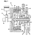
- FIG. 1 shows a cross-section of the double clutch provided according to the present invention.
- FIG. 2.1 shows a lateral view of the cam having lift curves.
- FIG. 2.2 shows a top view of the cam shown in the representation in FIG. 2.1 , in which the lift curves for the respective clutches are subdivided into curve segments.
- FIG. 3 shows the exemplary characteristic of actuating force F B of a clutch over actuating path S B of the clutch spring.
- FIG. 4 shows a variant of the characteristic of the torque at the electric motor generating the clutch shift operation.
- FIG. 5 shows the characteristics of clutch force and actuator force, each plotted over the translatory position of the cam.
- FIG. 6 shows the actuating path of the clutch springs assigned to the two clutches, plotted over the rotational angle of the electric motor that is used for the clutch shift operation.
- FIG. 1 A schematic cross-section of the double clutch according to the present invention is illustrated in the representation shown in FIG. 1 .
- a double-clutch transmission including two subunits, to each of which one clutch is respectively assigned, transmits the torque generated in a combustion engine 12 to a drive shaft 22 of the first subunit or a drive shaft 24 of the second subunit that surrounds drive shaft 22 .
- the combustion engine is usually a multi-cylinder combustion engine, whether it be self-igniting or a combustion engine having an externally supplied ignition, indicated here by a piston 14 whose vertical motion is transformed into a rotational motion via a crankshaft 16 .
- the rotational motion of crankshaft 16 of combustion engine 12 is transmitted to a clutch block 18 of double clutch 10 that is surrounded by a housing 20 .
- a first clutch 26 and a second clutch 28 of a double clutch 10 of a double-clutch transmission 10 are located within housing 20 of double-clutch transmission 10 .
- First clutch 26 is situated toward the inside, while second clutch 28 is situated toward the outside.
- Both clutches 26 , 28 of double clutch 10 are accordingly accommodated concentrically to each other within housing 20 of the double-clutch transmission. Clutches of equal size may also be used.
- a first clutch spring 30 is assigned to first clutch 26 , while second clutch 28 is acted upon via a second clutch spring 32 .
- First clutch spring 30 acts upon a bearing 50 of first clutch 26 , which in turn braces itself on clutch block 18 .
- second clutch spring 32 presses on a bearing 52 of second clutch 28 .
- Clutch block 18 of the double-clutch transmission is accordingly acted upon by both clutches 26 , 28 of double clutch 10 in the engaged state.
- first clutch 26 includes a first clutch disk 46
- second clutch 28 has a second clutch disk 48 .
- Second clutch disk 48 of the second outer clutch 28 is, as implied by FIG. 1 , enclosed by clutch block 18 .
- a first electric drive 38 and a second electric drive 40 are provided for actuating both clutches 26 , 28 .
- Cam 34 shown in FIG. 1 is moved by first electric drive 38 in a rotating fashion (cf. arrow 42 ) around the axis of drive shafts 22 , 24 in both directions of rotation.
- first electric drive 38 the clutch shift operation between first clutch 26 and second clutch 28 is controlled as a function of the progression of the lift curves 60 , 70 on cam 34 .
- First clutch spring 30 is in contact with a first lift curve 60
- second clutch spring 32 is in contact with an additional second lift curve 70 on cam 34 via a sphere-shaped transmission element, for example.
- first electric drive 38 which is provided for a clutch shift operation
- cam 34 rotates in accordance with the rotational path indicated by arrow 42 , whereby first lift curve 60 and second lift curve 70 are moved in a rotary manner. Since the mentioned, for example, sphere-shaped, transmission elements of first clutch spring 30 or second clutch spring 32 run on the contact surfaces of first lift curve 60 or second lift curve 70 not shown in FIG. 1 , the initial force acting on first clutch 26 and second clutch 28 is modified by a rotating motion of cam 34 .
- first electric drive 38 producing the clutch shift operation between the two clutches 26 , 28 of double clutch 10 of the double-clutch transmission is rotated by a particular angle, whereby a corresponding amount of energy is expended to engage one of the two clutches 26 , 28 .
- the same amount of energy from the disengage operation of the respective other of the two clutches 26 , 28 is released. This means that apart from the system friction, no energy is required to rotate first electric drive 38 .
- FIG. 1 A side or a top view of the cams shown schematically in FIG. 1 is illustrated in the representations shown in FIGS. 2.1 and 2 . 2 .
- cam 34 has a second lift curve 70 extending on the outer side and a first lift curve 60 situated concentrically to it, but radially farther inward, on its front sides facing clutch 26 and 28 respectively.
- Cam 34 is able to be moved in a rotating manner around drive shaft 22 of the first subunit and around drive shaft 24 of the second subunit around axis 42 .
- cam 34 is able to be shifted in translatory direction 44 via a sliding sleeve 36 . It can be gathered from the side view shown in FIG. 2.1 that first, inner lift curve 60 for activating first clutch 26 , and second lift curve 70 for activating second clutch 28 each have different profiles.
- First clutch spring 30 and second clutch spring 32 brace themselves on contact surfaces 80 of first lift curve 60 or second lift curve 70 , via the mentioned, for example, sphere-shaped transmission elements, thus making it possible to influence the clutch forces.
- first, inner lift curve 60 for actuating first clutch 26 has, for example, four curve segments 62 , 64 , 66 and 68 for reducing the surface pressure that occurs.
- second lift curve 70 which is situated radially outwards, for actuating second clutch 28 also includes multiple segments, for example, four, which are indicated by reference symbols 72 , 74 , 76 and 78 .
- one, for example, sphere-shaped transmission element of first clutch spring 30 for actuating first clutch 26 runs on each of the curve segments 62 , 64 , 66 and 68 of first lift curve 60
- one, for example, sphere-shaped transmission element of second clutch spring 32 for actuating second clutch 28 rolls on each curve segment 72 , 74 , 76 , 78 of the second, radially outward lift curve 70 .
- the respective contact surfaces of individual segments 62 , 64 , 66 and 68 of first lift curve 60 and curve segments 72 , 74 , 76 , 78 of second, radially outward second lift curve 70 are assigned reference symbol 80 .
- Lift curves 60 and 70 are oriented in opposite directions so that the highest elevations of curve 60 respectively stand opposite the lowest elevations of curve 70 and vice versa.
- clutch springs 30 and 32 are preloaded. This means that clutch springs 30 and 32 apply a force to cam 34 even if clutches 26 and 28 are completely disengaged.
- FIG. 4 shows a possible variation of the torque characteristic at the electric drive provided for the clutch shift operation relative to the previously described design variant.
- a variant for torque M E of first electric drive 38 provided for the clutch shift operation is plotted over rotational angle 94 of first electric drive 38 .
- the acting spring forces move cam 34 into one of the end positions of rotational angle 94 .
- This is achieved by modifying the curve or the profile of lift curves 60 , 70 or of their curve segments 62 , 64 , 66 and 68 or 72 , 74 , 76 and 78 in a manner that deviates from the approach described above.
- the change in energy ⁇ E over rotational angle 94 is no longer constant. Rather, as indicated in FIG. 4 , a ramp-shaped transition sets in between drive area 29 and entrainment area 92 with regard to first electric drive 38 , while in the formulation
- Torque M E which is adjusted via this modification of first and second lift curve 60 and 70 respectively is preferably greater than the friction torque that is generated by clutches 26 and 28 respectively to ensure a reliable further rotation or backward rotation of cam 34 without actuation by first electric drive 38 .
- the load may be removed from both clutches 26 , 28 if cam 34 is pulled away from clutch springs 30 or 32 in translatory direction 44 .
- first electric drive 38 transitions from drive mode 90 to an entrainment mode 92 .
- first electric drive 38 no longer drives, but rather is carried along.
- clutch force F K and actuator force F A are respectively plotted over different translatory positions P i of cam 34 , which are obtained according to the position targeted by the additional second electric drive 40 . It can be gathered from the characteristic of clutch force F K over translatory positions P i of cam 34 that a significant increase in clutch force F K is obtained after traversing empty path 1 .
- Reference symbol 96 labels an initial position of cam 34 . On the basis of the initial position represented by reference symbol 96 , a reduction or an increase of clutch force F K may be achieved by a translatory motion 44 of cam 34 over sliding sleeve 36 (compare representation shown in FIG. 1 ).
- clutch force F K may be increased by the additional second electric drive 40 via a translatory movement in translation direction 44 by cam 34 .
- Initial position 96 of cam 34 ensures that the entire clutch actuator system in the unenergized state of both first electric drive 38 and second electric drive 40 is in one of two defined secure states achieved by a compression spring 112 : Either first clutch 26 is disengaged and second clutch 28 transmits the defined torque, or second clutch 28 is disengaged while first clutch 26 transmits the defined torque.
- clutch 26 is disengaged and clutch 28 is engaged in end position 100 while reversed relationships prevail in end position 102 .
- cam 34 is twisted by a rotation 94 of first electric drive 38 , one of the two clutches 26 or 28 is respectively engaged while the respective other of the two clutches 26 , 28 of double clutch 10 is disengaged.
- This predefined curve may be varied by shifting cam 34 in translation direction 44 using second electric drive 40 along motion direction 106 .
Landscapes
- Engineering & Computer Science (AREA)
- General Engineering & Computer Science (AREA)
- Mechanical Engineering (AREA)
- Physics & Mathematics (AREA)
- Electromagnetism (AREA)
- Mechanical Operated Clutches (AREA)
- Hydraulic Clutches, Magnetic Clutches, Fluid Clutches, And Fluid Joints (AREA)
- One-Way And Automatic Clutches, And Combinations Of Different Clutches (AREA)
Applications Claiming Priority (4)
| Application Number | Priority Date | Filing Date | Title |
|---|---|---|---|
| DE102006008226 | 2006-02-22 | ||
| DE102006008226.5 | 2006-02-22 | ||
| DE102006008226A DE102006008226A1 (de) | 2006-02-22 | 2006-02-22 | Doppelkupplung für ein Doppelkupplungsgetriebe |
| PCT/EP2007/050394 WO2007096212A1 (de) | 2006-02-22 | 2007-01-16 | Doppelkupplung für ein doppelkupplungsgetriebe |
Publications (2)
| Publication Number | Publication Date |
|---|---|
| US20090301835A1 US20090301835A1 (en) | 2009-12-10 |
| US8151961B2 true US8151961B2 (en) | 2012-04-10 |
Family
ID=37965111
Family Applications (1)
| Application Number | Title | Priority Date | Filing Date |
|---|---|---|---|
| US12/223,548 Expired - Fee Related US8151961B2 (en) | 2006-02-22 | 2007-01-16 | Double clutch for a double-clutch transmission |
Country Status (6)
| Country | Link |
|---|---|
| US (1) | US8151961B2 (de) |
| EP (1) | EP1989462B1 (de) |
| JP (1) | JP4904370B2 (de) |
| CN (1) | CN101389879B (de) |
| DE (2) | DE102006008226A1 (de) |
| WO (1) | WO2007096212A1 (de) |
Cited By (1)
| Publication number | Priority date | Publication date | Assignee | Title |
|---|---|---|---|---|
| US20100108456A1 (en) * | 2006-09-25 | 2010-05-06 | Robert Bosch Gmbh | Dual clutch for a dual clutch transmission |
Families Citing this family (18)
| Publication number | Priority date | Publication date | Assignee | Title |
|---|---|---|---|---|
| DE102007034568A1 (de) * | 2007-07-25 | 2009-01-29 | Bayerische Motoren Werke Aktiengesellschaft | Fahrzeug mit einem Getriebe und einer Kupplungsanordnung |
| DE102008052448B4 (de) * | 2007-11-15 | 2018-12-06 | Schaeffler Technologies AG & Co. KG | Doppelkupplungsgetriebe und Verfahren zu dessen Steuerung |
| DE102008012894A1 (de) * | 2008-03-06 | 2009-09-10 | Zf Friedrichshafen Ag | Betätigungseinrichtung für eine Reibungskupplungseinrichtung und von diesen gebildete Drehmomentübertragungseinrichtung |
| DE102008013054B4 (de) | 2008-03-06 | 2010-04-22 | Getrag Getriebe- Und Zahnradfabrik Hermann Hagenmeyer Gmbh & Cie Kg | Stellmechanismus zum Ein- und Ausrücken einer Trennkupplung mit drehbarem Kurvensegment |
| GB2477121A (en) * | 2010-01-22 | 2011-07-27 | Gm Global Tech Operations Inc | Self-locking electromechanical clutch actuator having a worm gear |
| JP5461314B2 (ja) * | 2010-06-08 | 2014-04-02 | 本田技研工業株式会社 | クラッチ装置 |
| EP2677190B1 (de) * | 2011-02-14 | 2015-12-09 | Aichi Kikai Kogyo Kabushiki Kaisha | Kupplungsschaltvorrichtung und doppelkupplungsgetriebe mit einer kupplungsschaltvorrichtung |
| DE102011006969A1 (de) * | 2011-04-07 | 2012-10-11 | Zf Friedrichshafen Ag | Vorrichtung zum Verändern eines Betriebszustandes wenigsten eines Schaltelementes |
| JP5786678B2 (ja) * | 2011-09-01 | 2015-09-30 | 株式会社ジェイテクト | 駆動力伝達装置 |
| DE102012209348B3 (de) * | 2012-06-04 | 2013-05-29 | Bayerische Motoren Werke Aktiengesellschaft | Verfahren zum zugkraftunterbrechungsfreien Schalten eines Getriebes sowie zugkraftunterbrechungsfrei schaltbares Getriebe und Fahrzeug mit einem derartigen Getriebe |
| KR101284253B1 (ko) * | 2012-11-01 | 2013-07-09 | 씨스톤 테크놀로지스(주) | 더블 클러치 액츄에이터 |
| KR101490917B1 (ko) * | 2013-07-17 | 2015-02-06 | 현대자동차 주식회사 | 하이브리드 전기 자동차용 더블 클러치 장치 |
| KR101786219B1 (ko) * | 2015-11-18 | 2017-10-17 | 현대자동차주식회사 | 더블 클러치조립체 및 그의 브레이크기구 |
| DE102016210572A1 (de) * | 2016-06-14 | 2017-12-14 | Zf Friedrichshafen Ag | Doppelkupplungsgetriebevorrichtung sowie Kraftfahrzeug |
| TR201714404A1 (tr) * | 2017-09-27 | 2019-04-22 | Ford Otomotiv Sanayi As | Çi̇ft kavramali debri̇yaj si̇stemi̇ |
| TR201716967A2 (tr) * | 2017-11-01 | 2019-05-21 | Ford Otomotiv Sanayi As | Bi̇r çi̇ft kavramali debri̇yaj akti̇vasyon mekani̇zmasi |
| DE102019201980A1 (de) * | 2019-02-14 | 2020-08-20 | Robert Bosch Gmbh | Doppelkupplungsgetriebe für ein Elektrofahrzeug und Antriebseinheit für ein Elektrofahrzeug |
| CN113294455B (zh) * | 2021-04-27 | 2023-01-03 | 浙江吉利控股集团有限公司 | 用于离合器的电液执行机构及其控制方法 |
Citations (15)
| Publication number | Priority date | Publication date | Assignee | Title |
|---|---|---|---|---|
| DE19903554A1 (de) | 1999-01-29 | 2000-08-17 | Daimler Chrysler Ag | Kraftfahrzeug-Antriebsstrang und Verfahren zu seiner Steuerung |
| JP2001132779A (ja) | 1999-11-02 | 2001-05-18 | Daihatsu Motor Co Ltd | 自動クラッチ装置 |
| US6292732B1 (en) | 2000-03-20 | 2001-09-18 | General Motors Corporation | Adaptive on-coming clutch fill control for an automatic transmission |
| FR2810708A1 (fr) | 2000-06-22 | 2001-12-28 | Peugeot Citroen Automobiles Sa | Dispositif de transmission et de maintien du couple |
| JP2003097597A (ja) | 2001-09-27 | 2003-04-03 | Nsk Ltd | 自動クラッチレリーズ装置及びクラッチ装置 |
| DE10313435A1 (de) | 2002-03-27 | 2003-10-09 | Luk Lamellen & Kupplungsbau | Kupplungsausrücksystem für ein Doppelkupplungsgetriebe eines Kraftfahrzeuges |
| DE10316419A1 (de) | 2002-04-10 | 2003-11-06 | Luk Lamellen & Kupplungsbau | Verfahren zur Erkennung einer Leckage eines hydraulischen Ausrücksystems einer Doppelkupplung eines Paralleschaltgetriebes |
| EP1369613A1 (de) | 2002-06-07 | 2003-12-10 | Magneti Marelli Powertrain S.p.A. | Doppelkupplungsgetriebe für ein Kraftfahrzeug |
| US6668994B2 (en) * | 2000-02-15 | 2003-12-30 | Luk Lamellen Und Kupplungsbau Beteiligungs Kg | Torque transfer device |
| US6722483B2 (en) * | 2001-07-13 | 2004-04-20 | Volkswagen Ag | Twin clutch |
| US20050205376A1 (en) | 2004-03-19 | 2005-09-22 | Kemper Yves J | Ramp actuator |
| US20070080004A1 (en) * | 2005-10-11 | 2007-04-12 | Luk Lamellen Und Kupplungsbau Beteiligungs Kg | Drive train for a motor vehicle and method for operating such a drive train |
| US7338403B2 (en) * | 2004-08-30 | 2008-03-04 | Magna Powertrain Usa, Inc. | Torque coupling with power-operated clutch actuator |
| US7387590B2 (en) * | 2004-08-19 | 2008-06-17 | Luk Lamellen Und Kupplungsbau Beteiligungs Kg | Motor vehicle gear device as well as method for control of a motor vehicle |
| US7546914B2 (en) * | 2005-07-29 | 2009-06-16 | Magna Powertrain Ag & Co Kg | All-wheel transmission system |
Family Cites Families (1)
| Publication number | Priority date | Publication date | Assignee | Title |
|---|---|---|---|---|
| DE10334867B4 (de) * | 2003-07-29 | 2015-08-06 | Volkswagen Ag | Betätigungseinheit für die Doppelkupplung eines Kraftfahrzeuges |
-
2006
- 2006-02-22 DE DE102006008226A patent/DE102006008226A1/de not_active Withdrawn
-
2007
- 2007-01-16 US US12/223,548 patent/US8151961B2/en not_active Expired - Fee Related
- 2007-01-16 CN CN2007800062735A patent/CN101389879B/zh not_active Expired - Fee Related
- 2007-01-16 EP EP07703909A patent/EP1989462B1/de not_active Expired - Fee Related
- 2007-01-16 DE DE502007005043T patent/DE502007005043D1/de active Active
- 2007-01-16 WO PCT/EP2007/050394 patent/WO2007096212A1/de active Application Filing
- 2007-01-16 JP JP2008555722A patent/JP4904370B2/ja not_active Expired - Fee Related
Patent Citations (15)
| Publication number | Priority date | Publication date | Assignee | Title |
|---|---|---|---|---|
| DE19903554A1 (de) | 1999-01-29 | 2000-08-17 | Daimler Chrysler Ag | Kraftfahrzeug-Antriebsstrang und Verfahren zu seiner Steuerung |
| JP2001132779A (ja) | 1999-11-02 | 2001-05-18 | Daihatsu Motor Co Ltd | 自動クラッチ装置 |
| US6668994B2 (en) * | 2000-02-15 | 2003-12-30 | Luk Lamellen Und Kupplungsbau Beteiligungs Kg | Torque transfer device |
| US6292732B1 (en) | 2000-03-20 | 2001-09-18 | General Motors Corporation | Adaptive on-coming clutch fill control for an automatic transmission |
| FR2810708A1 (fr) | 2000-06-22 | 2001-12-28 | Peugeot Citroen Automobiles Sa | Dispositif de transmission et de maintien du couple |
| US6722483B2 (en) * | 2001-07-13 | 2004-04-20 | Volkswagen Ag | Twin clutch |
| JP2003097597A (ja) | 2001-09-27 | 2003-04-03 | Nsk Ltd | 自動クラッチレリーズ装置及びクラッチ装置 |
| DE10313435A1 (de) | 2002-03-27 | 2003-10-09 | Luk Lamellen & Kupplungsbau | Kupplungsausrücksystem für ein Doppelkupplungsgetriebe eines Kraftfahrzeuges |
| DE10316419A1 (de) | 2002-04-10 | 2003-11-06 | Luk Lamellen & Kupplungsbau | Verfahren zur Erkennung einer Leckage eines hydraulischen Ausrücksystems einer Doppelkupplung eines Paralleschaltgetriebes |
| EP1369613A1 (de) | 2002-06-07 | 2003-12-10 | Magneti Marelli Powertrain S.p.A. | Doppelkupplungsgetriebe für ein Kraftfahrzeug |
| US20050205376A1 (en) | 2004-03-19 | 2005-09-22 | Kemper Yves J | Ramp actuator |
| US7387590B2 (en) * | 2004-08-19 | 2008-06-17 | Luk Lamellen Und Kupplungsbau Beteiligungs Kg | Motor vehicle gear device as well as method for control of a motor vehicle |
| US7338403B2 (en) * | 2004-08-30 | 2008-03-04 | Magna Powertrain Usa, Inc. | Torque coupling with power-operated clutch actuator |
| US7546914B2 (en) * | 2005-07-29 | 2009-06-16 | Magna Powertrain Ag & Co Kg | All-wheel transmission system |
| US20070080004A1 (en) * | 2005-10-11 | 2007-04-12 | Luk Lamellen Und Kupplungsbau Beteiligungs Kg | Drive train for a motor vehicle and method for operating such a drive train |
Cited By (2)
| Publication number | Priority date | Publication date | Assignee | Title |
|---|---|---|---|---|
| US20100108456A1 (en) * | 2006-09-25 | 2010-05-06 | Robert Bosch Gmbh | Dual clutch for a dual clutch transmission |
| US9010510B2 (en) * | 2006-09-25 | 2015-04-21 | Robert Bosch Gmbh | Dual clutch for a dual clutch transmission |
Also Published As
| Publication number | Publication date |
|---|---|
| WO2007096212A1 (de) | 2007-08-30 |
| DE102006008226A1 (de) | 2007-08-23 |
| EP1989462B1 (de) | 2010-09-15 |
| EP1989462A1 (de) | 2008-11-12 |
| CN101389879A (zh) | 2009-03-18 |
| JP2009527708A (ja) | 2009-07-30 |
| US20090301835A1 (en) | 2009-12-10 |
| JP4904370B2 (ja) | 2012-03-28 |
| DE502007005043D1 (de) | 2010-10-28 |
| CN101389879B (zh) | 2011-01-12 |
Similar Documents
| Publication | Publication Date | Title |
|---|---|---|
| US8151961B2 (en) | Double clutch for a double-clutch transmission | |
| US8690723B2 (en) | Method for controlling a shiftable planetary gear set in a belt pulley plane of a drivetrain | |
| US20140033844A1 (en) | Step-variable transmission for a motor vehicle | |
| JP4241946B2 (ja) | 自動車のパワートレーンにおけるユニットを操作する装置 | |
| US7798109B2 (en) | Internal combustion engine with a variable compression ratio | |
| US8000868B2 (en) | Method and control unit for controlling a friction clutch between an internal combustion engine and a change speed transmission | |
| US20070199790A1 (en) | Process and device for adjusting a friction clutch located in a drive train of a vehicle and actuated by an actuator | |
| CN103375577B (zh) | 车辆双离合器变速器的可调式热管理 | |
| KR100869183B1 (ko) | 기어박스를 가진 자동차와 자동차의 이용방법 | |
| US6545372B2 (en) | Hybrid motor for a vehicle | |
| EP2689978A1 (de) | Kupplungssteuervorrichtung für ein hybridfahrzeug | |
| JP2013519846A (ja) | 連結装置 | |
| JP2003525409A (ja) | 自動車用の自動歯車駆動装置 | |
| US11236809B2 (en) | Driveline for a vehicle including an electric drive motor and a powershift transmission having at least two transmission stages | |
| US8617031B2 (en) | Method for controlling an automated friction clutch | |
| BR102017000934A2 (pt) | Controller for vehicle and control method | |
| US20060260897A1 (en) | Apparatus for the adjustment capability of two frictional shifting components | |
| CN108698509B (zh) | 用于全轮驱动系统的旋转多模式离合器模块 | |
| US20170274895A1 (en) | Power Transmission Device For Hybrid Vehicle | |
| CN109764099B (zh) | 用于控制车辆推进系统的无级变速器的方法和系统 | |
| US9670973B2 (en) | Method to control the torque transfer rate of a clutch, clutch control unit for a clutch and transmission with such a control unit | |
| MXPA06013806A (es) | Embrague. | |
| JP6985880B2 (ja) | 車両の制御装置 | |
| KR20130000383A (ko) | 마찰 클러치의 제어 방법 | |
| KR102663275B1 (ko) | 하이브리드-추진 자동차를 위한 클러치리스 자동 변속기를 제어하기 위한 방법 및 시스템 |
Legal Events
| Date | Code | Title | Description |
|---|---|---|---|
| AS | Assignment |
Owner name: ROBERT BOSCH GMBH, GERMANY Free format text: ASSIGNMENT OF ASSIGNORS INTEREST;ASSIGNOR:TUMBACK, STEFAN;REEL/FRAME:022271/0701 Effective date: 20080911 |
|
| REMI | Maintenance fee reminder mailed | ||
| LAPS | Lapse for failure to pay maintenance fees | ||
| STCH | Information on status: patent discontinuation |
Free format text: PATENT EXPIRED DUE TO NONPAYMENT OF MAINTENANCE FEES UNDER 37 CFR 1.362 |
|
| FP | Expired due to failure to pay maintenance fee |
Effective date: 20160410 |