US8130901B2 - Limiting an X-ray beam in connection with dental imaging - Google Patents
Limiting an X-ray beam in connection with dental imaging Download PDFInfo
- Publication number
- US8130901B2 US8130901B2 US12/531,747 US53174708A US8130901B2 US 8130901 B2 US8130901 B2 US 8130901B2 US 53174708 A US53174708 A US 53174708A US 8130901 B2 US8130901 B2 US 8130901B2
- Authority
- US
- United States
- Prior art keywords
- plate
- plate element
- slot
- elements
- moved
- Prior art date
- Legal status (The legal status is an assumption and is not a legal conclusion. Google has not performed a legal analysis and makes no representation as to the accuracy of the status listed.)
- Expired - Fee Related, expires
Links
Images


Classifications
-
- A—HUMAN NECESSITIES
- A61—MEDICAL OR VETERINARY SCIENCE; HYGIENE
- A61B—DIAGNOSIS; SURGERY; IDENTIFICATION
- A61B6/00—Apparatus or devices for radiation diagnosis; Apparatus or devices for radiation diagnosis combined with radiation therapy equipment
- A61B6/50—Apparatus or devices for radiation diagnosis; Apparatus or devices for radiation diagnosis combined with radiation therapy equipment specially adapted for specific body parts; specially adapted for specific clinical applications
- A61B6/51—Apparatus or devices for radiation diagnosis; Apparatus or devices for radiation diagnosis combined with radiation therapy equipment specially adapted for specific body parts; specially adapted for specific clinical applications for dentistry
-
- A—HUMAN NECESSITIES
- A61—MEDICAL OR VETERINARY SCIENCE; HYGIENE
- A61B—DIAGNOSIS; SURGERY; IDENTIFICATION
- A61B6/00—Apparatus or devices for radiation diagnosis; Apparatus or devices for radiation diagnosis combined with radiation therapy equipment
- A61B6/06—Diaphragms
-
- G—PHYSICS
- G21—NUCLEAR PHYSICS; NUCLEAR ENGINEERING
- G21K—HANDLING OF PARTICLES OR IONISING RADIATION NOT OTHERWISE PROVIDED FOR; IRRADIATION DEVICES; GAMMA RAY OR X-RAY MICROSCOPES
- G21K1/00—Arrangements for handling particles or ionising radiation, e.g. focusing or moderating
- G21K1/02—Arrangements for handling particles or ionising radiation, e.g. focusing or moderating using diaphragms, collimators
-
- G—PHYSICS
- G21—NUCLEAR PHYSICS; NUCLEAR ENGINEERING
- G21K—HANDLING OF PARTICLES OR IONISING RADIATION NOT OTHERWISE PROVIDED FOR; IRRADIATION DEVICES; GAMMA RAY OR X-RAY MICROSCOPES
- G21K1/00—Arrangements for handling particles or ionising radiation, e.g. focusing or moderating
- G21K1/02—Arrangements for handling particles or ionising radiation, e.g. focusing or moderating using diaphragms, collimators
- G21K1/04—Arrangements for handling particles or ionising radiation, e.g. focusing or moderating using diaphragms, collimators using variable diaphragms, shutters, choppers
-
- G—PHYSICS
- G21—NUCLEAR PHYSICS; NUCLEAR ENGINEERING
- G21K—HANDLING OF PARTICLES OR IONISING RADIATION NOT OTHERWISE PROVIDED FOR; IRRADIATION DEVICES; GAMMA RAY OR X-RAY MICROSCOPES
- G21K1/00—Arrangements for handling particles or ionising radiation, e.g. focusing or moderating
- G21K1/02—Arrangements for handling particles or ionising radiation, e.g. focusing or moderating using diaphragms, collimators
- G21K1/04—Arrangements for handling particles or ionising radiation, e.g. focusing or moderating using diaphragms, collimators using variable diaphragms, shutters, choppers
- G21K1/046—Arrangements for handling particles or ionising radiation, e.g. focusing or moderating using diaphragms, collimators using variable diaphragms, shutters, choppers varying the contour of the field, e.g. multileaf collimators
Definitions
- the present invention relates to methods and apparatus for limiting an x-ray beam in connection with dental extra oral imaging.
- Dental radiography has been traditionally considered including so-called intraoral imaging, which typically means imaging individual or a few teeth, extra oral imaging the most common imaging modes of which being so-called panoramic imaging, which means producing a layer image, i.e. a tomogram of the dental arch, and so-called cephalometric imaging, which typically means producing a transillumination image of the area of an entire skull.
- intraoral imaging typically means imaging individual or a few teeth
- panoramic imaging which means producing a layer image, i.e. a tomogram of the dental arch
- cephalometric imaging typically means producing a transillumination image of the area of an entire skull.
- cephalometric imaging typically means producing a transillumination image of the area of an entire skull.
- the same dental imaging apparatus is used for taking both panoramic and cephalometric images.
- use of the dental panoramic x-ray apparatus has expanded for producing various special images of different parts of the dental arch and even for 3D imaging.
- prior art dental panoramic x-ray imaging apparatuses include various kinds of adjustable and/or replaceable plate constructions, i.e. collimators.
- Collimators according to prior art may constitute one or more plates and/or the plates may include a number of different apertures.
- the x-ray beam must be limited correspondingly by using an aperture of different shape and/or size.
- the space available in imaging apparatus often imposes certain restrictions as to the number of different apertures that can be arranged in a single plate as well as to the number of plates as such that can be arranged into the apparatus.
- the plates are arranged releasably connected and changeable, the arrangements needed allowing the replacement also involve certain problems regarding convenience of use of the apparatus.
- a storage system must be arranged for the plates that are not in use at a given time.
- One prior art solution is to use e.g. a so-called four-plate-type collimator for limiting the beam both vertically and horizontally, in which each of the plates are driven by a separate actuator.
- the construction allows various beam sizes and forms to be provided for various imaging modes.
- the use of several actuators leads to increased cost of the construction, to complex electronics for controlling the actuators and to a certain space requirement for the actuators.
- the object of the current invention is to reach new solutions in view of the problems discussed above, especially in view of complexity and space requirements of the collimator constructions.
- the method and apparatus of the invention are characterized by at least first and second movable plate elements including first and second respective slots which overlap to form a beam-limiting aperture wherein the first plate element is moved by an actuator of a drive mechanism independently of the location of the second plate element whereas the second plate element is moved solely by and dependent on the movements of the first plate element.
- the current invention provides the advantage of making it possible to adjust the shape of the aperture limiting an x-ray beam of an extra oral imaging apparatus in two dimensions at a reasonable cost by using a single collimator construction and one actuator only.
- the space the construction occupies in the imaging apparatus may be arranged to be reasonable yet x-ray beams of different shapes in two dimensions may be formed without having to arrange the plate elements replaceable.
- Reasonable number of components only is needed to realize the construction.
- FIG. 1 a presents a front view of plate elements of a first plate mechanism according to the invention
- FIG. 1 b presents a front view of the plate elements of the first plate mechanism of FIG. 1 a , the plate elements being positioned in a different respective position,
- FIGS. 2 a and 2 b present front views of plate elements of two other embodiments of the plate mechanism according to the invention.
- FIGS. 3 a and 3 b present axiometric front and back views of yet another plate mechanism according to the invention.
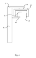
- FIG. 4 presents typical dental extra oral x-reimaging apparatus in which the plate mechanism according to the invention is primarily designed to be used.
- FIGS. 1 a and 1 b present a front view of plate elements of one embodiment of the invention. These figures show the plates only, a drive mechanism of the plate mechanism according to the invention will be discussed further below.
- the plate mechanism ( 1 ) comprises a first plate element ( 2 ) and a second plate element ( 3 ).
- the first plate element ( 2 ) includes a first slot ( 12 ) and the second plate element ( 3 ) includes a second slot ( 13 ).
- the first slot ( 12 ) of the first plate element ( 2 ) is arranged to be rectangular and its horizontal dimension to be substantially smaller than its vertical dimension.
- the second slot ( 13 ) is arranged to have two portions of different heights.
- the construction is designed to make possible arranging the slots ( 12 , 13 ) of the first and second plate elements ( 2 , 3 ) to lie on top of each other, by arranging at least portions of the plate elements ( 2 , 3 ) movable on different planes.
- the first slot ( 12 ) is arranged to be at least as high as is the distance from the lowest point of the second slot ( 13 ) to the highest point of the second slot ( 13 ).
- the second slot ( 13 ) is arranged to be at least as wide as the first slot ( 12 )—or, actually, each portion of the second slot ( 13 ) having a constant height is arranged to be at least as wide as the first slot ( 12 ).
- the form of the x-ray beam having passed the construction will be defined by the width of the first slot ( 12 ) and by the height of the second slot ( 13 ).
- FIG. 1 b presents a front view of the plate mechanism of FIG. 1 a with the plate elements ( 2 , 3 ) in different respective positions.
- the locations of the slots ( 12 , 13 ) is such that the width of the x-ray beam having passed the construction will be defined by the width of the first slot ( 12 ) and the height by the second slot ( 13 ), now by another portion of the second slot ( 13 ) than in FIG. 1 a .
- the x-ray beam will be lower than when the plate elements ( 2 , 3 ) are position according to FIG. 1 a.
- the second plate element ( 3 ) may be arranged to include a second slot ( 13 ) having many portions of different heights as well as portions whose lowest and highest points are on different horizontal levels. Further, the second plate element ( 3 ) may be arranged to include two or several separate slots ( 13 ) of different heights and/or slots ( 13 ) being located at different horizontal levels—in view of FIGS. 2 a and 2 b , as if corresponding the portions of different heights of the somewhat complex single slot ( 13 ) of FIG. 2 a .
- the first slot ( 12 ) is arranged to be at least as high as is the distance from the lowest point of the second slot ( 13 ) to the highest point of the second slot ( 13 )—or from the lowest point of the slot ( 13 ) located lowest on the second plate element ( 3 ) to the highest point of the slot ( 13 ) located highest on the second plate element ( 3 ).
- the second slot ( 13 ) is arranged to be at least as wide as the first slot ( 12 )—or, actually, each portion of the second slot ( 13 ) having a constant height is arranged to be at least as wide as the first slot ( 12 ). Incase there is more than one slot ( 13 ) in the second plate element ( 3 ), the same dimension criteria apply for each of the slots ( 13 ).
- the embodiment of only one slot ( 13 ) is obviously preferable.
- more than one slot ( 13 ) is to be arranged in the second plate element ( 3 )
- the embodiment shown in FIG. 2 b is drawn basically just to demonstrate separation of the various portions of the second slot ( 13 ) of FIG. 2 a ; according to a preferable embodiment of the invention, spacing of the slots ( 13 ) would be tighter.
- the first and second plate elements ( 2 , 3 ) of the plate mechanism ( 1 ) of the invention are arranged movable with respect to each other such that at least portions of the plate elements ( 2 , 3 ) move on different planes thus allowing an overlapping positioning of the first and second slots ( 12 , 13 ).
- the plate elements ( 2 , 3 ) are arranged as flat and movable on different planes in their entirety, but it is also possible to arrange the plate elements ( 2 , 3 ) to have such a construction that only parts of the plate elements ( 2 , 3 ) move on different planes, to allow for an overlapping positioning of the slots ( 12 , 13 ).
- the first and second plate elements ( 2 , 3 ) of FIGS. 3 a and 3 b are basically like those in FIGS. 1-2 , the only difference being in the more complex shape of the second slot ( 13 ) of the second plate element ( 3 ).
- the basic components of the drive mechanism of FIGS. 3 a and 3 b include an actuator (a motor) ( 4 ), a drive screw ( 5 ) and a nut ( 6 ) arranged in fixed connection with the first plate element ( 2 ) via a connection element ( 7 ), which goes through an elongated hole ( 21 ) arranged in a frame element ( 20 ) that supports the plate construction ( 1 ).
- the second plate element ( 3 ) is also supported on the frame element ( 20 ) by pegs ( 8 ), which extend through the same elongated hole ( 21 ).
- the frame element ( 20 ) further includes a guide groove ( 22 ), along which matching elements ( 24 ), arranged both to the first and second plate elements ( 2 , 3 ), are arranged to slide (matching elements of the first plate element not being visible in the FIGS. 3 a and 3 b ).
- the frame element ( 20 ) also includes an aperture ( 23 ) for the x-rays generated at the radiation source to go through.
- the constructions which support the plate elements ( 2 , 3 ) on the frame element ( 20 ) may include e.g. springs to keep the constructions table yet at the same time not to cause such an amount of friction between the guide groove ( 22 ) and the matching elements ( 24 ) that the plate elements ( 2 , 3 ) could't slide along the guide groove ( 22 ).
- An essential feature of the plate construction according to the invention is that the second plate element ( 3 ) can be driven to a desired position within the operation range of the plate mechanism by using the single actuator ( 4 ) of to the construction, said actuator ( 4 ) being primarily arranged to move the first plate element ( 2 ) by the drive construction of the plate mechanism ( 1 ).
- the idea is to arrange the construction such that when moving the first plate element ( 2 ) towards either end of its operation range, at some stage during such a movement the plate elements ( 2 , 3 ) will meet, directly or via some construction arranged for this purpose, after which any further movement of the first plate element ( 2 ) in that direction will cause the second plate element ( 3 ) to move in that same direction, too.
- another essential aspect of the construction is to include such a range within its operation range that, when changing the direction of movement of the first plate element ( 2 ) back towards the end opposite to the end towards which it was moving, the contact between the first and second plate elements ( 2 , 3 ) will be broken and only the first plate element ( 2 ) will be moving.
- the direction of movement of the first plate element ( 2 ) is changed, when having been in director indirect contact with the second plate element ( 3 ), there is always a distance within the operation range of the system within which the first plate element ( 2 ) will move alone, i.e.
- the second plate element ( 3 ) can never move independently of the movement of the first plate element ( 2 ), whereas the first plate element ( 2 ) can move both independently without moving the second plate element ( 3 ) as well as such that it moves the second plate element ( 3 ).
- a construction according to the invention makes it possible to first drive the second plate element ( 3 ) to a desired position within the operation range of the mechanism, in order to arrange the second slot ( 13 ) of the second plate element ( 3 ) to a desired position, after which the direction of movement of the first plate element ( 2 ) is reversed to drive the first slot ( 12 ) of the first plate element ( 2 ), now moving alone, to its desired position with respect to the position of the second plate element ( 3 ) to form an aperture which then will be defined by the overlapping slots ( 12 , 13 ) of the first and second plate elements ( 2 , 3 ).
- the distance between the pegs ( 8 ) supporting the second plate element ( 3 ) is arranged to be greater than the width of the first plate element ( 2 ) so that, depending on the respective positions of the first and second plate elements ( 2 , 3 ), either the first plate element ( 2 ) will move alone or it will also move the second plate element ( 3 )—towards that end of the elongated opening ( 21 )/the guide groove ( 22 ) the first plate element is moving.
- the second plate element ( 3 ) will begin to move when an edge of the fist plate element ( 2 ) meets either one of the pegs ( 8 ) (the locking elements ( 9 )) being fixed to the second plate element ( 3 ) but, obviously, there are a number of other kinds of constructions by which the same function may be achieved.
- the ends of the operation range of the plate construction ( 1 ) may be defined by the ends of either the elongated slot ( 21 ) or the guide groove ( 22 ), or by both, for example.
- the distance the first plate element ( 2 ) is arranged to be moved corresponds at least the width of a single second slot ( 13 ) of the second plate element ( 2 ), or the distance between the outermost slots ( 13 ) of the second plate element ( 3 ).
- the first plate element ( 2 ) basically defining position of the beam limited by the construction, is driven by the actuator ( 4 ) and the second plate element ( 3 ) via the movements of the first plate element ( 2 ).
- the actuator ( 4 ) is to directly drive specifically that plate element which defines position of the beam.
- rectangular x-ray beams can be created having a width defined by the first slot ( 12 ) of the first plate element ( 2 ) and the height and the horizontal position defined by the second slot ( 13 ) of the second plate element ( 3 ).
- Various kinds of such x-ray beams are needed e.g. in such dental radiology being based on scanning imaging techniques.
- slots ( 13 ) having heights of about 26 mm and about 22 mm, respectively, may be arranged in the second plate element ( 3 ).
- rectangular slots extending about 14 mm from the highest horizontal level of that of the slot arranged for panoramic imaging for adults may be arranged in view of panoramic scan of the dental arch of the upper jaw only, and a corresponding slot in view of imaging the dental arch of the lower jaw.
- corresponding slots may be arranged also in view of imaging the upper and lower jaws of children, and e.g. one in view of a panoramic scan excluding the jawbone.
- the scope of the current invention is not limited to specifically those forms and respective dimensions of apertures creatable by the slots shown in FIGS. 1-3 , even though already by e.g. such a collimator construction shown in FIGS. 3 a and 3 b , one is able to cover a number of typical x-ray beam sizes and beam positions typically used in a dental extra oral x-ray apparatus.
- Alternative or additional slot forms may be e.g. triangular ones enabling stepless adjustment of a dimension of the aperture, one having a height suitable for cephalometric imaging (imaging of the whole skull) and apertures of more complex forms than a rectangle or a triangle, such as ones having at least one curved edge.
- more than one slot may be arranged either to the first or second plate element, or to both of them, there may be slots arranged not only next to each other but also on top of each other, and such a construction is also possible where the second plate element includes only one slot and the first plate element a slot or slots of various heights.
- a plate element may also be arranged to include both a more complex type aperture such as shown in FIGS. 2 a and 3 a , for example, and additionally one or more bare rectangles, for example. Further, either the first or the second plate element may be arranged to be the one being closer to the x-ray source.
- the plate construction according to the invention preferably comprises a means for detecting position of the first plate element within its operation range, even though the construction can be used even without such means as well by e.g. always starting a positioning-drive-sequence of the plate elements by driving the plates to an end of the operation range of the construction. This done, one will always know where the plate elements are positioned upon starting positioning of the plates, and by using e.g. a stepping motor one will be able to keep track of whereto the elements have been moved.
- Control system for the plate construction preferably includes pre-defined drive sequences for the plate elements, to be used in connection with typical imaging modes applied by the imaging apparatus.
- the user interface may include the option of driving the actuator ‘manually’ as well, for fine-tuning purposes of positioning the beam, for example.
- the collimator according to the current invention is primarily designed for use as a so-called primary collimator in a dental panoramic x-ray apparatus.
- a typical such apparatus is shown in FIG. 4 , comprising a column-like body part ( 42 ) and a cantilever-type supporting element ( 43 ) mounted on the upper end of the body part ( 42 ), possibly pivotally so as to enable rotation of it with respect to the body part ( 42 ).
- an imaging arm often called a C-arm ( 45 ) is arranged for supporting an image data receiver ( 47 ) and an X-ray source( 46 ).
- the mounting construction ( 44 ) for the C-arm ( 45 ) is designed to enable rotation of the C-arm ( 45 ) and horizontal movement of the rotation center of the C-arm ( 45 ).
- Attached to the column-like body ( 42 ) is arranged a patient support element ( 48 ).
- the apparatus may also be arranged to be used for e.g. cephalometric imaging by integrating a cephalometric imaging station to it (not shown in the Fig.), arranged at the end of a separate support arm mounted on the body part ( 42 ).
- the plate mechanism ( 1 ) is arranged within the cover of the x-ray source ( 46 ), as facing the image data receiver ( 47 ).
- the frame element ( 20 ) of the plate mechanism ( 1 ) may be arranged to be a part of the x-ray tube housing such that, in view of FIG. 3 a , for example, the first plate element ( 2 ) will be facing the x-ray source ( 46 ) and the second plate element ( 3 ) the patient/the image data receiver ( 47 ).
- the cantilever-type supporting element ( 43 ) may also be mounted on a wall or a ceiling.
Landscapes
- Health & Medical Sciences (AREA)
- Life Sciences & Earth Sciences (AREA)
- Engineering & Computer Science (AREA)
- Physics & Mathematics (AREA)
- Medical Informatics (AREA)
- High Energy & Nuclear Physics (AREA)
- Radiology & Medical Imaging (AREA)
- Molecular Biology (AREA)
- Veterinary Medicine (AREA)
- Nuclear Medicine, Radiotherapy & Molecular Imaging (AREA)
- Optics & Photonics (AREA)
- Pathology (AREA)
- Public Health (AREA)
- Biomedical Technology (AREA)
- Heart & Thoracic Surgery (AREA)
- Biophysics (AREA)
- Surgery (AREA)
- Animal Behavior & Ethology (AREA)
- General Health & Medical Sciences (AREA)
- Spectroscopy & Molecular Physics (AREA)
- General Engineering & Computer Science (AREA)
- Dentistry (AREA)
- Oral & Maxillofacial Surgery (AREA)
- Apparatus For Radiation Diagnosis (AREA)
Applications Claiming Priority (3)
| Application Number | Priority Date | Filing Date | Title |
|---|---|---|---|
| FI20070221A FI122093B (fi) | 2007-03-19 | 2007-03-19 | Röntgensädekeilan rajaaminen hammaslääketieteellisen kuvantamisen yhteydessä |
| FI20070221 | 2007-03-19 | ||
| PCT/EP2008/052864 WO2008113715A1 (en) | 2007-03-19 | 2008-03-11 | Limiting an x-ray beam in connection with dental imaging |
Publications (2)
| Publication Number | Publication Date |
|---|---|
| US20100119036A1 US20100119036A1 (en) | 2010-05-13 |
| US8130901B2 true US8130901B2 (en) | 2012-03-06 |
Family
ID=37930023
Family Applications (1)
| Application Number | Title | Priority Date | Filing Date |
|---|---|---|---|
| US12/531,747 Expired - Fee Related US8130901B2 (en) | 2007-03-19 | 2008-03-11 | Limiting an X-ray beam in connection with dental imaging |
Country Status (7)
| Country | Link |
|---|---|
| US (1) | US8130901B2 (de) |
| EP (1) | EP2139398B1 (de) |
| JP (1) | JP5220774B2 (de) |
| KR (1) | KR101160791B1 (de) |
| CN (1) | CN101668483B (de) |
| FI (1) | FI122093B (de) |
| WO (1) | WO2008113715A1 (de) |
Cited By (6)
| Publication number | Priority date | Publication date | Assignee | Title |
|---|---|---|---|---|
| US20160343462A1 (en) * | 2014-02-10 | 2016-11-24 | Siemens Healthcare Gmbh | Single source dual energy having two filters for x-ray spectrum differentiation in the case of radiator screens having slotted plates |
| US20170287581A1 (en) * | 2016-03-30 | 2017-10-05 | Cefla Societá Cooperativa | Beam-limiting device for radiographic apparatuses |
| US20170352444A1 (en) * | 2016-06-06 | 2017-12-07 | University Of Florida Research Foundation, Incorporated | Rotating radiation shutter collimator |
| US9991014B1 (en) * | 2014-09-23 | 2018-06-05 | Daniel Gelbart | Fast positionable X-ray filter |
| US10627529B2 (en) | 2017-07-07 | 2020-04-21 | International Business Machines Corporation | Real time X-ray dosimeter using diodes with variable thickness degrader |
| US20200146650A1 (en) * | 2018-11-09 | 2020-05-14 | Palodex Group Oy | Calibrating an x-ray medical imaging device for cephalometric imaging |
Families Citing this family (12)
| Publication number | Priority date | Publication date | Assignee | Title |
|---|---|---|---|---|
| FR2953707B1 (fr) * | 2009-12-16 | 2012-03-02 | Trophy | Appareil de radiologie dentaire fournissant une image cephalometrique et procede associe |
| US9004757B2 (en) * | 2010-03-24 | 2015-04-14 | PaloDEx Grou Oy | Systems, assemblies, computer readable media and methods for medical imaging |
| DE102010013591A1 (de) * | 2010-03-31 | 2011-10-06 | DüRR DENTAL AG | Röntgengerät und Verfahren zur Herstellung von Röntgenbildern für die zahnmedizinische oder kieferorthopädische Diagnostik |
| US8586955B2 (en) * | 2010-09-22 | 2013-11-19 | Ko Khee Tay | Apparatus and method for attenuating high energy radiation based on detected vehicle type |
| KR101175027B1 (ko) * | 2011-02-25 | 2012-08-17 | 이화여자대학교 산학협력단 | 카메라가 구비된 구강 내 엑스선 촬영장치 |
| CN102288626A (zh) * | 2011-07-18 | 2011-12-21 | 中国原子能科学研究院 | 中子织构测试设备 |
| US9208918B2 (en) * | 2012-11-16 | 2015-12-08 | Neurologica Corp. | Computerized tomography (CT) imaging system with multi-slit rotatable collimator |
| WO2015019232A2 (en) * | 2013-08-08 | 2015-02-12 | Controlrad Systems Inc. | X-ray reduction system |
| CN104545982A (zh) * | 2013-10-24 | 2015-04-29 | 南京普爱射线影像设备有限公司 | 一种四叶片牙科机限束器 |
| WO2016087912A1 (en) * | 2014-12-04 | 2016-06-09 | Trophy | Collimator for cephalometric extra oral dental imaging devices |
| US20190021683A1 (en) * | 2015-12-23 | 2019-01-24 | Trophy | Method and Device for Creating a Cephalometric Image |
| CN112971991B (zh) * | 2021-02-05 | 2022-11-11 | 上海电气集团股份有限公司 | 控制机械臂系统移动的方法及装置 |
Citations (15)
| Publication number | Priority date | Publication date | Assignee | Title |
|---|---|---|---|---|
| DE3236082A1 (de) | 1982-09-29 | 1984-03-29 | Siemens AG, 1000 Berlin und 8000 München | Strahlenblende fuer ein roentgenuntersuchungsgeraet |
| EP0236790A1 (de) | 1986-02-28 | 1987-09-16 | Siemens Aktiengesellschaft | Zahnärztliches Röntgendiagnostikgerät zur Erstellung von Panorama-Schichtaufnahmen vom Kiefer eines Patienten |
| US4783793A (en) | 1985-09-13 | 1988-11-08 | Planmeca Oy | X-ray apparatus for panoramic tomography including control system |
| FI894310A7 (fi) | 1988-09-13 | 1990-03-14 | Morita Mfg | Panorama -roentgenfotograferingsapparat. |
| US5086444A (en) * | 1990-02-16 | 1992-02-04 | Siemens Aktiengesellschaft | Primary radiation diaphragm |
| EP0485742A1 (de) | 1990-11-14 | 1992-05-20 | Siemens-Elema AB | Primärstrahlenblende für eine Röntgenröhre |
| US5991362A (en) * | 1996-11-15 | 1999-11-23 | Xre Corporation | Adjustable opening X-ray mask |
| US6148062A (en) * | 1997-11-03 | 2000-11-14 | Ge Medical Systems, S.A. | X-ray beam-shaping filter and X-ray imaging machine incorporating such a filter |
| US6289074B1 (en) * | 1998-09-02 | 2001-09-11 | J. Morita Manufacturing Corporation | X-ray computed tomography method and system |
| WO2002097827A1 (en) | 2001-05-29 | 2002-12-05 | Planmeca Oy | Method and apparatus for limiting a ray beam |
| WO2005048845A1 (en) | 2003-11-20 | 2005-06-02 | Ge Medical Systems Global Technology Company, Llc. | Collimator and radiation irradiator |
| WO2006108920A1 (en) | 2005-04-11 | 2006-10-19 | Planmeca Oy | Computer tomography apparatus |
| WO2006109808A1 (ja) | 2005-04-11 | 2006-10-19 | J. Morita Manufacturing Corporation | スカウトビュー機能を備えたx線撮影装置 |
| US7336768B2 (en) * | 2002-07-08 | 2008-02-26 | Kabushiki Kaishi Toshiba | X-ray diagnosis apparatus |
| US20090022270A1 (en) * | 2005-04-11 | 2009-01-22 | J. Morita Manufacturing Corporation | X-Ray Image Sensor and X-Ray Imaging Apparatus Using the Same |
Family Cites Families (2)
| Publication number | Priority date | Publication date | Assignee | Title |
|---|---|---|---|---|
| US4362422A (en) * | 1980-09-12 | 1982-12-07 | Zinkann Paul J | Grating fastener |
| JPS63119939U (de) | 1987-01-30 | 1988-08-03 |
-
2007
- 2007-03-19 FI FI20070221A patent/FI122093B/fi active IP Right Grant
-
2008
- 2008-03-11 KR KR1020097021579A patent/KR101160791B1/ko not_active Expired - Fee Related
- 2008-03-11 JP JP2009553998A patent/JP5220774B2/ja not_active Expired - Fee Related
- 2008-03-11 CN CN200880013832XA patent/CN101668483B/zh not_active Expired - Fee Related
- 2008-03-11 EP EP08717611.1A patent/EP2139398B1/de active Active
- 2008-03-11 US US12/531,747 patent/US8130901B2/en not_active Expired - Fee Related
- 2008-03-11 WO PCT/EP2008/052864 patent/WO2008113715A1/en not_active Ceased
Patent Citations (18)
| Publication number | Priority date | Publication date | Assignee | Title |
|---|---|---|---|---|
| DE3236082A1 (de) | 1982-09-29 | 1984-03-29 | Siemens AG, 1000 Berlin und 8000 München | Strahlenblende fuer ein roentgenuntersuchungsgeraet |
| US4783793A (en) | 1985-09-13 | 1988-11-08 | Planmeca Oy | X-ray apparatus for panoramic tomography including control system |
| EP0236790A1 (de) | 1986-02-28 | 1987-09-16 | Siemens Aktiengesellschaft | Zahnärztliches Röntgendiagnostikgerät zur Erstellung von Panorama-Schichtaufnahmen vom Kiefer eines Patienten |
| FI894310A7 (fi) | 1988-09-13 | 1990-03-14 | Morita Mfg | Panorama -roentgenfotograferingsapparat. |
| DE3930022A1 (de) | 1988-09-13 | 1990-03-15 | Morita Mfg | Dental-panoramaroentgenaufnahmevorrichtung, die auch schaedelaufnahmen erlaubt |
| US5058147A (en) | 1988-09-13 | 1991-10-15 | Kabushiki Kaisha Morita Seisakusho | Dental panoramic/cephalo X-ray photographing device |
| US5086444A (en) * | 1990-02-16 | 1992-02-04 | Siemens Aktiengesellschaft | Primary radiation diaphragm |
| EP0485742A1 (de) | 1990-11-14 | 1992-05-20 | Siemens-Elema AB | Primärstrahlenblende für eine Röntgenröhre |
| US5991362A (en) * | 1996-11-15 | 1999-11-23 | Xre Corporation | Adjustable opening X-ray mask |
| US6148062A (en) * | 1997-11-03 | 2000-11-14 | Ge Medical Systems, S.A. | X-ray beam-shaping filter and X-ray imaging machine incorporating such a filter |
| US6289074B1 (en) * | 1998-09-02 | 2001-09-11 | J. Morita Manufacturing Corporation | X-ray computed tomography method and system |
| WO2002097827A1 (en) | 2001-05-29 | 2002-12-05 | Planmeca Oy | Method and apparatus for limiting a ray beam |
| US7336768B2 (en) * | 2002-07-08 | 2008-02-26 | Kabushiki Kaishi Toshiba | X-ray diagnosis apparatus |
| WO2005048845A1 (en) | 2003-11-20 | 2005-06-02 | Ge Medical Systems Global Technology Company, Llc. | Collimator and radiation irradiator |
| EP1684637A1 (de) | 2003-11-20 | 2006-08-02 | GE Medical Systems Global Technology Company LLC | Kollimator und bestrahler |
| WO2006108920A1 (en) | 2005-04-11 | 2006-10-19 | Planmeca Oy | Computer tomography apparatus |
| WO2006109808A1 (ja) | 2005-04-11 | 2006-10-19 | J. Morita Manufacturing Corporation | スカウトビュー機能を備えたx線撮影装置 |
| US20090022270A1 (en) * | 2005-04-11 | 2009-01-22 | J. Morita Manufacturing Corporation | X-Ray Image Sensor and X-Ray Imaging Apparatus Using the Same |
Cited By (11)
| Publication number | Priority date | Publication date | Assignee | Title |
|---|---|---|---|---|
| US20160343462A1 (en) * | 2014-02-10 | 2016-11-24 | Siemens Healthcare Gmbh | Single source dual energy having two filters for x-ray spectrum differentiation in the case of radiator screens having slotted plates |
| US10123756B2 (en) * | 2014-02-10 | 2018-11-13 | Siemens Healthcare Gmbh | Single source dual energy having two filters for X-ray spectrum differentiation in the case of radiator screens having slotted plates |
| US9991014B1 (en) * | 2014-09-23 | 2018-06-05 | Daniel Gelbart | Fast positionable X-ray filter |
| US20170287581A1 (en) * | 2016-03-30 | 2017-10-05 | Cefla Societá Cooperativa | Beam-limiting device for radiographic apparatuses |
| US10937560B2 (en) * | 2016-03-30 | 2021-03-02 | Cefla Societá Cooperativa | Beam-limiting device for radiographic apparatuses |
| US20170352444A1 (en) * | 2016-06-06 | 2017-12-07 | University Of Florida Research Foundation, Incorporated | Rotating radiation shutter collimator |
| US10714227B2 (en) * | 2016-06-06 | 2020-07-14 | Georgetown Rail Equipment Company | Rotating radiation shutter collimator |
| US10627529B2 (en) | 2017-07-07 | 2020-04-21 | International Business Machines Corporation | Real time X-ray dosimeter using diodes with variable thickness degrader |
| US10634797B2 (en) | 2017-07-07 | 2020-04-28 | International Business Machines Corporation | Real time X-ray dosimeter using diodes with variable thickness degrader |
| US20200146650A1 (en) * | 2018-11-09 | 2020-05-14 | Palodex Group Oy | Calibrating an x-ray medical imaging device for cephalometric imaging |
| US11000256B2 (en) * | 2018-11-09 | 2021-05-11 | Palodex Group Oy | Calibrating an X-ray medical imaging device for cephalometric imaging |
Also Published As
| Publication number | Publication date |
|---|---|
| FI20070221A0 (fi) | 2007-03-19 |
| KR101160791B1 (ko) | 2012-06-27 |
| CN101668483B (zh) | 2012-02-15 |
| EP2139398B1 (de) | 2019-06-19 |
| JP5220774B2 (ja) | 2013-06-26 |
| CN101668483A (zh) | 2010-03-10 |
| JP2010533507A (ja) | 2010-10-28 |
| US20100119036A1 (en) | 2010-05-13 |
| KR20090127423A (ko) | 2009-12-11 |
| EP2139398A1 (de) | 2010-01-06 |
| FI20070221L (fi) | 2008-09-20 |
| FI122093B (fi) | 2011-08-31 |
| WO2008113715A1 (en) | 2008-09-25 |
Similar Documents
| Publication | Publication Date | Title |
|---|---|---|
| US20100119036A1 (en) | Limiting An X-Ray Beam In Connection With Dental Imaging | |
| EP1721574B1 (de) | Kombiniertes Röntgengerät für Panorama-, CT- und Cephalometrie-Aufnahmen | |
| EP1752100B1 (de) | Kombiniertes Röntgengerät für Panorama- und CT-Aufnahmen | |
| JP5757937B2 (ja) | 複合型パノラマ/コンピュータ断層撮影装置 | |
| US5511106A (en) | X-ray diagnostics installation for producing x-ray exposures of body parts of a patient | |
| US7236563B2 (en) | Combined panoramic and computed tomography photographing apparatus | |
| US6169780B1 (en) | X-ray apparatus with improved patient access | |
| JP5450615B2 (ja) | 歯科治療装置 | |
| WO2006109808A1 (ja) | スカウトビュー機能を備えたx線撮影装置 | |
| JP3931314B2 (ja) | 歯科用x線撮影装置 | |
| JP2009131656A (ja) | X線撮影装置 | |
| JP2004532417A (ja) | 光線ビームを限定する方法及び装置 | |
| US9750470B2 (en) | Aligning bite of X-ray device and X-ray device having the same | |
| JP2007159987A (ja) | X線撮影装置 | |
| HK1101495B (en) | The combined panoramic,computed tomography and cephalometric photographing apparatus | |
| HK1101496B (en) | The combined panoramic and computed tomography photographing apparatus | |
| HK1166456A (zh) | 组合式全景和计算x射线断层照相装置 |
Legal Events
| Date | Code | Title | Description |
|---|---|---|---|
| ZAAA | Notice of allowance and fees due |
Free format text: ORIGINAL CODE: NOA |
|
| ZAAB | Notice of allowance mailed |
Free format text: ORIGINAL CODE: MN/=. |
|
| AS | Assignment |
Owner name: PLANMECA OY, FINLAND Free format text: ASSIGNMENT OF ASSIGNORS INTEREST;ASSIGNOR:MULLER, TIMO;REEL/FRAME:027384/0539 Effective date: 20111214 |
|
| STCF | Information on status: patent grant |
Free format text: PATENTED CASE |
|
| FPAY | Fee payment |
Year of fee payment: 4 |
|
| MAFP | Maintenance fee payment |
Free format text: PAYMENT OF MAINTENANCE FEE, 8TH YEAR, LARGE ENTITY (ORIGINAL EVENT CODE: M1552); ENTITY STATUS OF PATENT OWNER: LARGE ENTITY Year of fee payment: 8 |
|
| FEPP | Fee payment procedure |
Free format text: MAINTENANCE FEE REMINDER MAILED (ORIGINAL EVENT CODE: REM.); ENTITY STATUS OF PATENT OWNER: LARGE ENTITY |
|
| LAPS | Lapse for failure to pay maintenance fees |
Free format text: PATENT EXPIRED FOR FAILURE TO PAY MAINTENANCE FEES (ORIGINAL EVENT CODE: EXP.); ENTITY STATUS OF PATENT OWNER: LARGE ENTITY |
|
| STCH | Information on status: patent discontinuation |
Free format text: PATENT EXPIRED DUE TO NONPAYMENT OF MAINTENANCE FEES UNDER 37 CFR 1.362 |
|
| FP | Lapsed due to failure to pay maintenance fee |
Effective date: 20240306 |