US809709A - Trunk. - Google Patents
Trunk. Download PDFInfo
- Publication number
- US809709A US809709A US27811305A US1905278113A US809709A US 809709 A US809709 A US 809709A US 27811305 A US27811305 A US 27811305A US 1905278113 A US1905278113 A US 1905278113A US 809709 A US809709 A US 809709A
- Authority
- US
- United States
- Prior art keywords
- tray
- rails
- trunk
- lid
- receptacle
- Prior art date
- Legal status (The legal status is an assumption and is not a legal conclusion. Google has not performed a legal analysis and makes no representation as to the accuracy of the status listed.)
- Expired - Lifetime
Links
- 238000010276 construction Methods 0.000 description 2
- 239000002184 metal Substances 0.000 description 2
- 230000000994 depressogenic effect Effects 0.000 description 1
- 230000003028 elevating effect Effects 0.000 description 1
- 239000000463 material Substances 0.000 description 1
Images
Classifications
-
- A—HUMAN NECESSITIES
- A45—HAND OR TRAVELLING ARTICLES
- A45C—PURSES; LUGGAGE; HAND CARRIED BAGS
- A45C5/00—Rigid or semi-rigid luggage
Definitions
- This invention relates to trunks of the type embodying an upper movabletray, and has for its objects to produce a comparatively simple inexpensive device of this character in which the tray may be readily moved to permit access being had to the contents of an underlying tray, one wherein the tracks or ways on which the upper tray travels subserve the further function of means for properly supporting the trunk-lid in open position, and one wherein the ways will when the lid is open be slightly elevated at their rear ends, thus to permit free movement of the tray without disturbing the underlying contents of the trunk.
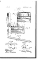
- Figure 1 is a vertical transverse section through a trunk embodying the invention and showing the parts in normal position with the lid closed.
- Fig. 2 is a similar view showing the lid open.
- Fig. 3 is a perspective view, on an enlarged scale, of one of the tracks or ways.
- Fig. 4 is a detail view, partly in longitudinal section. showing the manner of connecting the meeting ends of the rail-sections.
- Fig. 5 is a perspective view of one of the bearing members. 6 is a detail cross-section of one of the rar s.
- 1 designates a trunk or receptacle provided with a lid 2, hinged at 3 for vertical swinging movement to open position and equipped with a lower tray 4 and an upper tray 5, these parts being all of the usual or any preferred construction and material and adapted in practice to perform their ordinary functions.
- a pair of tracks or ways 6, on which the tray 5 is arranged for travel these rails or ways, which extend transversely of the trunk, being pivoted at their forward ends to the front wall of the latter by means of hinges 7 and con nected at their rear ends to the lid 2 by means of links 8, each pivoted at one end to the rear terminal. of one of the rails and at its other end to the adjacent end wall of the lid.
- the rails 6, which are preferably stamped or struck from sheet metal, each comprises a normally vertical portion or flange 9 and a horizontal portion or flange 10, which latter includes an upwardly-projecting beador tread 11 of substantially semicircular form in cross-section for a purpose which will presently appear, while pivoted at 12 to each of the rails and constituting a continuation thereof is a relatively movable section or extension 13,adapted to swing from its normally vertical position,
- the rail 6 will extend in a true horizontal plane with the sections 13 vertically disposed and lying in a space between the rear wall of tray 5 and the adjacent wall of the cover 2.
- the cover is raised, the parts will move to the position seen in Fig. 2, with the rail 6 inclined upwardly from its front to its rear end and the section 13 in alinement with the body of the rail and projecting into the cover 2, which latter will be supported in open position through the medium of the links 8, which, as before stated, are pivoted to the rear ends of the rails.
- the tray 5 may travel freely thereon without disturbing the contents of the underlying tray 4, and, furthermore, that owing to the rails projecting into the lid 2 the tray 5 may be moved rearwardl y a sufficient distance to permit free access being had to the contents of tray 4 or for permitting removal of the latter without removing the tray 5.
- bearing members 15 Attached to the tray 5 and for travel on the rails 6 are bearing members 15, each struck or stamped from sheet metal and comprising a vertical portion or flange 16, perforated for the reception of fastening members for securing it to the tray, and a horizontal portion or flange 17, having a central downwardly-projecting bearing portion or rib 18 of substantially semicircular form in cross-section and adapted to normally extend perpendicular to the longitudinal axis of the companion rail 6, the bearing portions 18 being adapted to contact with and for travel on the tread portions 11, thus to insure smooth and convenient movement of the tray.
- a receptacle having a movable tray, a movable cover for the receptacle, rails on which the tray travels, said rails being pivotally connected at one end with the receptacle, and means for elevating the other ends of the rails upon movement of the cover to open position.
- a receptacle having a movable cover, a movable way operatively connected at one end with the receptacle and at its other end with the cover for movement therewith in a vertical plane, and a tray arranged for movement on the way.
- a receptacle in a device of the class described, a receptacle, rails pivoted at one end thereof to said receptacle and having their other ends provided with relatively movable sections adapted to form continuations "of the rails, links pivoted to said sections and to the cover of said receptacle, where by movement of the latter to open position will elevate the adjacent ends of the rails,-and a tray arranged to travel on the rails.
- areceptacle having a lid or cover, rails pivoted at one end thereof to the receptacle and having their other ends provided with links pivoted to the said lid or cover, thus forming a tray rest and stay for thesupport of the lid, combined.
Landscapes
- Vehicle Step Arrangements And Article Storage (AREA)
Description
PATENTED JAN.' 9
T. J. LIVSIE.
TRUNK.
APPLICATION FILED SEPTJZ, 1905.
UNITED STATES PATENT FFTGE.
Specification of Letters Patent.
Patented Jan. 9, 1906.
Application filed September 12, 1905. Serial No. 278,113-
To all whom it may concern:
Be it known that I, THOMAS J. LIVSIE, a citizen of the United States, residing at Norfolk, in the county of Norfolk and State of Virginia, have invented new and useful Improvements in Trunks, of which the following is a specification.
This invention relates to trunks of the type embodying an upper movabletray, and has for its objects to produce a comparatively simple inexpensive device of this character in which the tray may be readily moved to permit access being had to the contents of an underlying tray, one wherein the tracks or ways on which the upper tray travels subserve the further function of means for properly supporting the trunk-lid in open position, and one wherein the ways will when the lid is open be slightly elevated at their rear ends, thus to permit free movement of the tray without disturbing the underlying contents of the trunk.
l/Vith these and other objects in view the invention comprises the novel features of construction and combination of parts more fully hereinafter described.
In the accompanying drawings, Figure 1 is a vertical transverse section through a trunk embodying the invention and showing the parts in normal position with the lid closed. Fig. 2 is a similar view showing the lid open. Fig. 3 is a perspective view, on an enlarged scale, of one of the tracks or ways. Fig. 4 is a detail view, partly in longitudinal section. showing the manner of connecting the meeting ends of the rail-sections. Fig. 5 is a perspective view of one of the bearing members. 6 is a detail cross-section of one of the rar s.
Referring to the drawings, 1 designates a trunk or receptacle provided with a lid 2, hinged at 3 for vertical swinging movement to open position and equipped with a lower tray 4 and an upper tray 5, these parts being all of the usual or any preferred construction and material and adapted in practice to perform their ordinary functions.
Disposed within the trunk 1 and respectively at opposite ends thereof is a pair of tracks or ways 6, on which the tray 5 is arranged for travel, these rails or ways, which extend transversely of the trunk, being pivoted at their forward ends to the front wall of the latter by means of hinges 7 and con nected at their rear ends to the lid 2 by means of links 8, each pivoted at one end to the rear terminal. of one of the rails and at its other end to the adjacent end wall of the lid. The rails 6, which are preferably stamped or struck from sheet metal, each comprises a normally vertical portion or flange 9 and a horizontal portion or flange 10, which latter includes an upwardly-projecting beador tread 11 of substantially semicircular form in cross-section for a purpose which will presently appear, while pivoted at 12 to each of the rails and constituting a continuation thereof is a relatively movable section or extension 13,adapted to swing from its normally vertical position,
as seen in Fig. 1, to a horizontal position in line with the main portion of the rail 6, as seen in Fig. 2. The meeting ends of the rail 6 and its extension 13 are adapted when the parts are in horizontal alinement to overlap each other, as seen more fully in Fig. 4, and in order to insure a neat joint and preserve continuity of the upper face of tread 11 the tread portion of section 13 is slightly depressed, as at 14, for proper overlapping engagement with the adjacent end of the tread portion of rail 6 for the above-stated purpose.
In practice when the parts are in normal position, as seen in Fig. l, the rail 6 will extend in a true horizontal plane with the sections 13 vertically disposed and lying in a space between the rear wall of tray 5 and the adjacent wall of the cover 2. When, however, the cover is raised, the parts will move to the position seen in Fig. 2, with the rail 6 inclined upwardly from its front to its rear end and the section 13 in alinement with the body of the rail and projecting into the cover 2, which latter will be supported in open position through the medium of the links 8, which, as before stated, are pivoted to the rear ends of the rails. It is to be particularly observed that owing to the rails being raised at their rear ends and given an upward inclination the tray 5 may travel freely thereon without disturbing the contents of the underlying tray 4, and, furthermore, that owing to the rails projecting into the lid 2 the tray 5 may be moved rearwardl y a sufficient distance to permit free access being had to the contents of tray 4 or for permitting removal of the latter without removing the tray 5.
Attached to the tray 5 and for travel on the rails 6 are bearing members 15, each struck or stamped from sheet metal and comprising a vertical portion or flange 16, perforated for the reception of fastening members for securing it to the tray, and a horizontal portion or flange 17, having a central downwardly-projecting bearing portion or rib 18 of substantially semicircular form in cross-section and adapted to normally extend perpendicular to the longitudinal axis of the companion rail 6, the bearing portions 18 being adapted to contact with and for travel on the tread portions 11, thus to insure smooth and convenient movement of the tray.
From the foregoing it is apparent thatI produce a simple inexpensive device admirably adapted for the attainment of the ends in view and one wherein the tray will move freely without-disturbing the underlying contents of the trunk.
Having thus fully described my invention, what I claim as new, anddesire to secure by Letters Patent, is
1. In a device of the class described, a receptacle having a movable tray, a movable cover for the receptacle, rails on which the tray travels, said rails being pivotally connected at one end with the receptacle, and means for elevating the other ends of the rails upon movement of the cover to open position.
3. In a device of the class described, a receptacle having a movable cover, a movable way operatively connected at one end with the receptacle and at its other end with the cover for movement therewith in a vertical plane, and a tray arranged for movement on the way.
4. In a device of the class described, a receptacle, rails pivoted at one end thereof to said receptacle and having their other ends provided with relatively movable sections adapted to form continuations "of the rails, links pivoted to said sections and to the cover of said receptacle, where by movement of the latter to open position will elevate the adjacent ends of the rails,-and a tray arranged to travel on the rails.
55. Ina device of the class described, areceptacle having a lid or cover, rails pivoted at one end thereof to the receptacle and having their other ends provided with links pivoted to the said lid or cover, thus forming a tray rest and stay for thesupport of the lid, combined.
In testimony whereof Iaifix my signature in presence of two witnesses.
THOMAS J. L IVSIE.
Witnesses:
C; L.=GoLosM1TH, JOHN .J. PITT.
Priority Applications (1)
| Application Number | Priority Date | Filing Date | Title |
|---|---|---|---|
| US27811305A US809709A (en) | 1905-09-12 | 1905-09-12 | Trunk. |
Applications Claiming Priority (1)
| Application Number | Priority Date | Filing Date | Title |
|---|---|---|---|
| US27811305A US809709A (en) | 1905-09-12 | 1905-09-12 | Trunk. |
Publications (1)
| Publication Number | Publication Date |
|---|---|
| US809709A true US809709A (en) | 1906-01-09 |
Family
ID=2878190
Family Applications (1)
| Application Number | Title | Priority Date | Filing Date |
|---|---|---|---|
| US27811305A Expired - Lifetime US809709A (en) | 1905-09-12 | 1905-09-12 | Trunk. |
Country Status (1)
| Country | Link |
|---|---|
| US (1) | US809709A (en) |
-
1905
- 1905-09-12 US US27811305A patent/US809709A/en not_active Expired - Lifetime
Similar Documents
| Publication | Publication Date | Title |
|---|---|---|
| US1247848A (en) | Paper box. | |
| US809709A (en) | Trunk. | |
| US750673A (en) | mason | |
| US371182A (en) | Half to john m | |
| US757194A (en) | Sectional filing-cabinet. | |
| US531010A (en) | Furniture | |
| US604334A (en) | Charles e | |
| US581664A (en) | Harrison s | |
| US696846A (en) | Trunk. | |
| US912921A (en) | Show-case. | |
| US1158132A (en) | Cigarette-box. | |
| US1194810A (en) | bellis | |
| US800558A (en) | Toy bank. | |
| US871779A (en) | Trunk-tray hinge. | |
| US380045A (en) | Isham melton | |
| US719474A (en) | Mail-box for rural free delivery. | |
| US677895A (en) | Keyless toy bank. | |
| US1543492A (en) | Workbox | |
| US906458A (en) | Display-reel. | |
| US1072258A (en) | Bookcase. | |
| US902737A (en) | Invalid's cabinet-commode. | |
| US929646A (en) | Hinge. | |
| US898549A (en) | Trunk. | |
| US399439A (en) | Trunk | |
| US311439A (en) | Sigismtjnd m |