US809274A - Spool-cabinet. - Google Patents
Spool-cabinet. Download PDFInfo
- Publication number
- US809274A US809274A US25724405A US1905257244A US809274A US 809274 A US809274 A US 809274A US 25724405 A US25724405 A US 25724405A US 1905257244 A US1905257244 A US 1905257244A US 809274 A US809274 A US 809274A
- Authority
- US
- United States
- Prior art keywords
- spool
- cabinet
- spindles
- base
- spools
- Prior art date
- Legal status (The legal status is an assumption and is not a legal conclusion. Google has not performed a legal analysis and makes no representation as to the accuracy of the status listed.)
- Expired - Lifetime
Links
- 238000010276 construction Methods 0.000 description 3
- 238000009958 sewing Methods 0.000 description 2
- 235000020004 porter Nutrition 0.000 description 1
Images
Classifications
-
- D—TEXTILES; PAPER
- D05—SEWING; EMBROIDERING; TUFTING
- D05B—SEWING
- D05B91/00—Tools, implements, or accessories for hand sewing
- D05B91/14—Thread-spool pins
Definitions
- This invention relates to improvements in spool-cabinets.
- the object of the invention is to provide a cabinet of this character adapted to contain spools and other sewing materials, whereby the same may be kept in convenient position and arrangement for use.
- a further object is to provide a simple, inexpensive, and ornamental device of this character which may be supported upon a shelf or table or hung upon the wall.
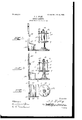
- Figure l is a sideelevation of the cabinet.
- Fig. 2' is a top plan view
- Fig. 3 is a central longitudinal vertical sectional view of the same.
- 1 denotes the cabinet, which consists of a base plate or board 2, on the rear end of which is arranged an upwardlyprojecting back piece 3.
- the forward portion of the base-plate 2 is preferably of circular form,and concentrically mounted thereon is an upright standard 4, on which is revolubly mounted a spool-rack 5.
- Said rack preferably consists of upper and lower circular plates 6 and 7, which are spaced apart and connected together by a centrallydisposed sleeve 8, through which is adapted to project the standard 4.
- Said spindles are adapted to be passed through the passages of the spools and through the apertures 9, thereby revolubly holding the spools between the plates 6 and 7 to permit the thread or other contents of the spools to be unreeled therefrom.
- By revolubly mounting the spool-rack 5 the same may be turned to bring the desired spool in reach without moving the cabinet.
- On the upper end of the standard 4 is secured a removable cushioned plate 13 to receive pins or needles.
- a box 14 On the base-plate 2 adjacent to the back piece 3 is arranged a box 14, said box being provided with a hinged cover 15 and is adapted to contain buttons or sewing material.
- a cleat 16 On the back piece 3 above the box 14 is secured a cleat 16, said cleat being spaced from the board to form slots or passages 17, which are adapted to receive scissors or othersewing implements.
- an opening 18 In the upper portion of the back part is formed an opening 18, by which the same may be engaged with a nail and hung upon the wall. If desired, the upper portion of the back board may be formed in ornamental design.
- a spool-cabinet constructed and arranged as herein shown and described will be found to be useful and convenient as well as ornamental and attractive in appearance.
- the herein-described spool-cabinet consisting of a base 2, an upright back 3 secured to said base and provided near its upper end with an opening 18, whereby said cabinet may be suspended from a wall or other support, a box 14 secured at the juncture of said base and back and provided with a cover 15 hinged to the back 3, a rack 16 projecting from and secured to the back and provided with openings 17 for supporting scissors and other implements, in upright position against the back 3, a spool-rack comprising a pair of horizontally-disposed disks 6, 7 connected together by a centrally-disposed sleeve 8, a standard 4, consisting of a rod passing through said disks and sleeve and supported upon the base In-testirnony whereof I have hereunto set 2, an annular series of removable spool-remy hand in presence of two subscribing Witceiving spindles 10 provided with heads 12. nesses.
Landscapes
- Engineering & Computer Science (AREA)
- Textile Engineering (AREA)
- Portable Nailing Machines And Staplers (AREA)
Description
PATBNTED JAN. 2, 1906.
J. A. EPLBY. SPOOL CABINET.
APPLIOATION FILED 3.24, 1905.
PATENT OFFICE.
JOHN A. EPLEY, OF IUKA, KANSAS.
SPOOL-CABINET.
Specification of Letters Patent.
Patented Jan. 2, 1906.
Application filed April 24, 1905. Serial No, 257,244.
To all whom it may concern:
Be it known that 1, JOHN A. EPLEY, a citizen ofthe United States,residing at luka, in the county of Prattand State of Kansas, have invented certain new and useful Improvements in Spool-Cabinets; and I do declare the following to be a full, clear, and exact description of the invention, such as will enable others skilled in the art to which it appertains to make and use the same.
This invention relates to improvements in spool-cabinets.
The object of the invention is to provide a cabinet of this character adapted to contain spools and other sewing materials, whereby the same may be kept in convenient position and arrangement for use.
A further object is to provide a simple, inexpensive, and ornamental device of this character which may be supported upon a shelf or table or hung upon the wall.
With these and other objects in view the invention consists of certain novel features of construction, combination, and arrangement of parts, as will be hereinafter described and claimed.
In the accompanying drawings, Figure l is a sideelevation of the cabinet. Fig. 2'is a top plan view, and Fig. 3 is a central longitudinal vertical sectional view of the same.
Referring more particularly to the drawings, 1 denotes the cabinet, which consists of a base plate or board 2, on the rear end of which is arranged an upwardlyprojecting back piece 3.
The forward portion of the base-plate 2 is preferably of circular form,and concentrically mounted thereon is an upright standard 4, on which is revolubly mounted a spool-rack 5. Said rack preferably consists of upper and lower circular plates 6 and 7, which are spaced apart and connected together by a centrallydisposed sleeve 8, through which is adapted to project the standard 4. In the plates 6 and 7, near the outer edges of the same, are formed annular series of alining apertures 9, through which are inserted spool-supporting spindles 10, said spindles being provided on their up per ends with heads 12, by which the spindles may be drawn out of the apertures 9 to permit a removal and replacing of the spool. Said spindles are adapted to be passed through the passages of the spools and through the apertures 9, thereby revolubly holding the spools between the plates 6 and 7 to permit the thread or other contents of the spools to be unreeled therefrom. By revolubly mounting the spool-rack 5 the same may be turned to bring the desired spool in reach without moving the cabinet. On the upper end of the standard 4 is secured a removable cushioned plate 13 to receive pins or needles.
On the base-plate 2 adjacent to the back piece 3 is arranged a box 14, said box being provided with a hinged cover 15 and is adapted to contain buttons or sewing material.
On the back piece 3 above the box 14 is secured a cleat 16, said cleat being spaced from the board to form slots or passages 17, which are adapted to receive scissors or othersewing implements. In the upper portion of the back part is formed an opening 18, by which the same may be engaged with a nail and hung upon the wall. If desired, the upper portion of the back board may be formed in ornamental design.
A spool-cabinet constructed and arranged as herein shown and described will be found to be useful and convenient as well as ornamental and attractive in appearance.
From the foregoing description, taken in connection with the accompanying drawings, the construction and operation of the invention will be readily understood Without requiring a more extended explanation.
Various changes in the form, proportion, and the minor details of construction may be resorted to without departing from the principle or sacrificing any of the advantages of this invention.
Having thus described my invention. what I claim as new, and desire to secure'by Letters Patent, is
The herein-described spool-cabinet consisting of a base 2, an upright back 3 secured to said base and provided near its upper end with an opening 18, whereby said cabinet may be suspended from a wall or other support, a box 14 secured at the juncture of said base and back and provided with a cover 15 hinged to the back 3, a rack 16 projecting from and secured to the back and provided with openings 17 for supporting scissors and other implements, in upright position against the back 3, a spool-rack comprising a pair of horizontally-disposed disks 6, 7 connected together by a centrally-disposed sleeve 8, a standard 4, consisting of a rod passing through said disks and sleeve and supported upon the base In-testirnony whereof I have hereunto set 2, an annular series of removable spool-remy hand in presence of two subscribing Witceiving spindles 10 provided with heads 12. nesses.
said spindles passing through the disks 6, 7 J. A. EPLEY. 5 to retain spools thereon, and a removable Witnesses:
needle-cushion 13 arranged on the upper end JAMES A. PORTER,
of the standard 4:, essentially as described. W. J. CHAFFIN.
Priority Applications (1)
| Application Number | Priority Date | Filing Date | Title |
|---|---|---|---|
| US25724405A US809274A (en) | 1905-04-24 | 1905-04-24 | Spool-cabinet. |
Applications Claiming Priority (1)
| Application Number | Priority Date | Filing Date | Title |
|---|---|---|---|
| US25724405A US809274A (en) | 1905-04-24 | 1905-04-24 | Spool-cabinet. |
Publications (1)
| Publication Number | Publication Date |
|---|---|
| US809274A true US809274A (en) | 1906-01-02 |
Family
ID=2877755
Family Applications (1)
| Application Number | Title | Priority Date | Filing Date |
|---|---|---|---|
| US25724405A Expired - Lifetime US809274A (en) | 1905-04-24 | 1905-04-24 | Spool-cabinet. |
Country Status (1)
| Country | Link |
|---|---|
| US (1) | US809274A (en) |
Cited By (1)
| Publication number | Priority date | Publication date | Assignee | Title |
|---|---|---|---|---|
| US5002211A (en) * | 1989-12-12 | 1991-03-26 | Caldwell Ruth E | Sewing accessory storage device |
-
1905
- 1905-04-24 US US25724405A patent/US809274A/en not_active Expired - Lifetime
Cited By (1)
| Publication number | Priority date | Publication date | Assignee | Title |
|---|---|---|---|---|
| US5002211A (en) * | 1989-12-12 | 1991-03-26 | Caldwell Ruth E | Sewing accessory storage device |
Similar Documents
| Publication | Publication Date | Title |
|---|---|---|
| US809274A (en) | Spool-cabinet. | |
| US564519A (en) | Wardrobe-shelf bracket | |
| US492316A (en) | Portable desk | |
| US1289448A (en) | Sewing companion. | |
| US304914A (en) | Work-box | |
| US858543A (en) | Wire basket. | |
| US510563A (en) | Work-box | |
| US214757A (en) | Improvement in work-boxes | |
| US1327581A (en) | Work-stand | |
| US1070611A (en) | Spool-cabinet. | |
| US470850A (en) | Hamilton rogers | |
| US1153021A (en) | Spool-carrier. | |
| US559364A (en) | Spool-box | |
| US659974A (en) | Saw-cabinet. | |
| US1293492A (en) | Sewing outfit. | |
| US569307A (en) | Spool-holder | |
| US138372A (en) | Improvement in work-boxes | |
| US853300A (en) | Laundry-stand. | |
| US620277A (en) | Work-holder for sewing-machines | |
| US865801A (en) | Lady's work-stand. | |
| US1446457A (en) | Sewing box | |
| US970470A (en) | Spool and work holder. | |
| US590704A (en) | Work-box | |
| US448484A (en) | Sewing-stand | |
| US280278A (en) | Easel attachment |