US809195A - Bobbin-tray. - Google Patents
Bobbin-tray. Download PDFInfo
- Publication number
- US809195A US809195A US25474105A US1905254741A US809195A US 809195 A US809195 A US 809195A US 25474105 A US25474105 A US 25474105A US 1905254741 A US1905254741 A US 1905254741A US 809195 A US809195 A US 809195A
- Authority
- US
- United States
- Prior art keywords
- wires
- tray
- frame
- bobbin
- pins
- Prior art date
- Legal status (The legal status is an assumption and is not a legal conclusion. Google has not performed a legal analysis and makes no representation as to the accuracy of the status listed.)
- Expired - Lifetime
Links
Images

Classifications
-
- B—PERFORMING OPERATIONS; TRANSPORTING
- B65—CONVEYING; PACKING; STORING; HANDLING THIN OR FILAMENTARY MATERIAL
- B65H—HANDLING THIN OR FILAMENTARY MATERIAL, e.g. SHEETS, WEBS, CABLES
- B65H49/00—Unwinding or paying-out filamentary material; Supporting, storing or transporting packages from which filamentary material is to be withdrawn or paid-out
- B65H49/18—Methods or apparatus in which packages rotate
- B65H49/20—Package-supporting devices
- B65H49/32—Stands or frameworks
-
- B—PERFORMING OPERATIONS; TRANSPORTING
- B65—CONVEYING; PACKING; STORING; HANDLING THIN OR FILAMENTARY MATERIAL
- B65H—HANDLING THIN OR FILAMENTARY MATERIAL, e.g. SHEETS, WEBS, CABLES
- B65H2701/00—Handled material; Storage means
- B65H2701/30—Handled filamentary material
- B65H2701/31—Textiles threads or artificial strands of filaments
Definitions
- My invention relates to new and useful improvements in bobbin-trays, such as are employed in textile mills to retain bobbins or tubes of filling or weft of the particular kind required according to the grade of fabric manufactured.
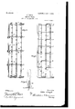
- FIG. 1 shows a plan view of a bobbintray constructed (to hold one hundred bobbins) in accordance with my invention.
- Fig. 2 is an end view of the same.
- Fig. 3 is a plan bins, and I) transverse or stay wires.
- FIG. 4 is a similar plan view of a slightly different form of construction of my tray
- Fig. 5 is a detail elevation of a modified form of pin and upon which I have shown a bobbin in dotted lines.
- my invention consists of a suitable metal frame, to which is secured a series of supporting and brace wires, one of which series contains a number of vertically-disposed pins formed of and integral with said wire. These pins are arranged at an equal distance apart and are adapted to receive and support the bobbins.
- the frame of this tray is shown formed in several different ways of square, round, and Hat steel and may obviously be constructed of either.
- A indicates the frame, as shown in the several drawings 5 B, the longitudinal supportingwires; C, the pins thereon to receive the bop- T e frame, as before stated, may be formed in any preferred manner and with suitable means for attachment of the supporting and stay wires-as, for instance, that shown in the drawings.
- Both the supporting and stay wires may be formed and attached separately, as shown in either Figs. l 2, and 3, or they may be formed integral and of a continuous piece of wire, as shown in Fig. 4.
- Figs. l and 2 the frame shown is provided with a channel E and a series of holes leading through the frame into said channel, through which holes the ends F of the supporting-wires B are inserted and bent over into the channel for the attachment of said wires to the frame, as is clearly illustrated in Figs. l and 2.
- These supporting-wires, as also the stay-wires,- may be attached to the frame by twisting the ends ofthe wire therearound, as indicated by O, Fig. 3.
- the bobbin-pins C supported on these wires, as before stated, are formed integral therewith and extend upward ata right angle to the longitudinal wire and are preferably twisted, as illustrated in Fig. 2 of the drawings, to securely bind together their two portions to strengthen and statten the same.
- the lower portion of the pin may be soldered, if desired; but in practice I nd this is not necessary.
- supporting-wires are arranged at an equal distance apart, and the pins of the respective Wires are arranged alternately and diagonally with respect to the pins of the adjoining supports, so as to obtain the greatest amount of space possible in a tray of a specified size.
- These supporting-wires are provided with stay-wires to retain and support them in their relative positions. This stay-wire is attached to the supporting-wire in any preferred manner-as, for instance, by means of solder, as indicated by G in Fig. l, or by coiling it around said supporting-wire, as at H, or weaving it intermediate thereof, as shown in Fig. 4.
- the ends of these stay-wires may be attached to the frame in any suitable way-as, for instance, by passing the ends I through the frame and bending them over in a groove J, as shown in Fig. l, or by coiling them around the frame, as shown by O in Fig. 3.
- Fig. 4 I have shown each series of supporting and stay wires formed integral of a single piece, both said stay and supporting wires being laced back and forward across the frame around lugs L of the frame and interwoven with each other to strengthen and stiflen the tray.
- Fig. 5 I have .shown a detail view of pin M, which is iormedfrom the continuous wire by simply carrying it up and back and soldering the lower end to connect, as indicated by N.
Landscapes
- Storage Of Web-Like Or Filamentary Materials (AREA)
Description
.Lea.
2 SHEETS PKATBNVTED JAN. 2, 1906.
l J. LLOYD'. BOBBIN TRAY.
APPLIUATION'PILED 11111.10. 1905.
.9AM @f1/QW PATENTED JAN. 2, 1906.
J. LLOYD.
BOBBIN TRAY.
APPLICATION FILED APR.10. 1905.
2 SHEETS-SHEET 2.
JOHN LLOYD, OF BRIDGEPORT, CONNECTICUT.
BOBBlN-TRAY.
Specification of Letters Patent. I
Application filed April 10, 1905. Serial No. 254.741.
Patented Jan. 2, 155064 T0 all whom, it may concern:
Be it known that I, JOHN LLOYD, a subject of the King of Great Britain, and a resident of Bridgeport, in the county of Fairfield and State of Connecticut, have invented certain new and useful Improvements in Bobbin- Trays, of which the following is a specification.
My invention relates to new and useful improvements in bobbin-trays, such as are employed in textile mills to retain bobbins or tubes of filling or weft of the particular kind required according to the grade of fabric manufactured.
Heretofore various forms of devices or trays have been employed for the above purpose, the most popular construction being that of an ordinary wood box or receptacle wherein the bobbins are thrown and allowed to remain in more or less of a disordered condition, whichfrequently means the entanglement and waste of material. This form of receptacle is further objectionable, for the reason that while these boxes are supposed to contain a certain number of bobbins requisite for a specific pattern length or kind of fabric, yet as a matter of fact some of the bobbins frequently become lost or misplaced, and the absence thereof is not apparent without counting over the entire lot.
It is therefore the object of my invention to provide a tray which may be constructed to contain any specified number of bobbins and in a way that the filling or thread of the respective bobbins will not become entangled or damaged by engagement with the adjacent bobbins further, to construct the trayin such a manner that at a glance it maybe determined whether or not the full and required number of bobbins are present, and, finally, to provide a tray which will be durable in construction, practical in use,comparatively inexpensive to manufacture, and especially convenient and desirable for the user.
With the above and other minor objects in view my invention resides and consists in the novel construction and arrangements of parts shown upon the accompanying drawings, forming a part of this specification, upon which similar characters of reference denote like or corresponding parts throughout the several figures, and of which* Figure 1 shows a plan view of a bobbintray constructed (to hold one hundred bobbins) in accordance with my invention. Fig. 2 is an end view of the same. Fig. 3 is a plan bins, and I) transverse or stay wires.
view, partly broken away, of a tray constructed in accordance with my invention and produced entirely from wire. Fig. 4 is a similar plan view of a slightly different form of construction of my tray, and Fig. 5 is a detail elevation of a modified form of pin and upon which I have shown a bobbin in dotted lines.
As will be seen from the several iigures of the drawings, my invention consists of a suitable metal frame, to which is secured a series of supporting and brace wires, one of which series contains a number of vertically-disposed pins formed of and integral with said wire. These pins are arranged at an equal distance apart and are adapted to receive and support the bobbins. The frame of this tray is shown formed in several different ways of square, round, and Hat steel and may obviously be constructed of either.
Referring in detail to the characters of reference marked upon the drawings, A indicates the frame, as shown in the several drawings 5 B, the longitudinal supportingwires; C, the pins thereon to receive the bop- T e frame, as before stated, may be formed in any preferred manner and with suitable means for attachment of the supporting and stay wires-as, for instance, that shown in the drawings. Both the supporting and stay wires may be formed and attached separately, as shown in either Figs. l 2, and 3, or they may be formed integral and of a continuous piece of wire, as shown in Fig. 4.
In Figs. l and 2 the frame shown is provided with a channel E and a series of holes leading through the frame into said channel, through which holes the ends F of the supporting-wires B are inserted and bent over into the channel for the attachment of said wires to the frame, as is clearly illustrated in Figs. l and 2. These supporting-wires, as also the stay-wires,- may be attached to the frame by twisting the ends ofthe wire therearound, as indicated by O, Fig. 3. The bobbin-pins C, supported on these wires, as before stated, are formed integral therewith and extend upward ata right angle to the longitudinal wire and are preferably twisted, as illustrated in Fig. 2 of the drawings, to securely bind together their two portions to strengthen and stiften the same. In addition to this twisting the lower portion of the pin may be soldered, if desired; but in practice I nd this is not necessary. The said IOO IIO
supporting-wires are arranged at an equal distance apart, and the pins of the respective Wires are arranged alternately and diagonally with respect to the pins of the adjoining supports, so as to obtain the greatest amount of space possible in a tray of a specified size. These supporting-wires are provided with stay-wires to retain and support them in their relative positions. This stay-wire is attached to the supporting-wire in any preferred manner-as, for instance, by means of solder, as indicated by G in Fig. l, or by coiling it around said supporting-wire, as at H, or weaving it intermediate thereof, as shown in Fig. 4. The ends of these stay-wires, like the supporting-wires, may be attached to the frame in any suitable way-as, for instance, by passing the ends I through the frame and bending them over in a groove J, as shown in Fig. l, or by coiling them around the frame, as shown by O in Fig. 3.
In Fig. 4 I have shown each series of supporting and stay wires formed integral of a single piece, both said stay and supporting wires being laced back and forward across the frame around lugs L of the frame and interwoven with each other to strengthen and stiflen the tray.
In Fig. 5 I have .shown a detail view of pin M, which is iormedfrom the continuous wire by simply carrying it up and back and soldering the lower end to connect, as indicated by N.
Having thus described my invention, what I claim, and desire to secure by Letters Patent, is-
1. In a bobbin-tray the combination with a frame, of a series of longitudinal wire supports, each bearing a series of pins arranged at proper distances apart, and transverse stay-wires to engage the longitudinal Wires intermediate of the pins.
2. In a bobbin-tray of, the class described, the combination with a suitable frame, of a series of supporting-wires attached thereto, each containing pins formed at a right angle to and of the wires of the support, and transverse stay-wires to engage said supportingwires intermediate of said pins and arranged at a right angle thereto.
8. In a bobbin-tray of the class described, the combination with a frame, of a series of longitudinal Wire supports attached thereto, a series of twisted pins formed of and integral with the wire ofthe supports, and transverse stay-wires connecting the longitudinal supports.
4. In a bobbin-tray of the class described, the combination with a frame, of a series of wire supports arranged parallel and attached to said l'rame, a series of twisted pins disposed thereirom formed of and integral with the wires of the support, and wires arranged at a right angle to said supports for retaining said supporting-wires at a proper distance apart.
5. In a bobbin-tray of the class described, the combination with a suitable frame, of parallel supporting-wires, each having a series of folded and twisted loops therein to form pins, wires for retaining said loops in a closed vposition, and Wires `for retaining the supportingwires at a proper distance apart.
6. In a bobbin-tray of the class described, the combination with a substantially rectangular frame, of a series of longitudinal wire supports attached thereto and containing integral pins, and transverse wires connecting the frame and supports intermediate of the said pins.
7. In a bobbin-tray of the class described, the combination with a suitable frame, of a series of parallel wire supports connected to the ends of the Jframe, a series of pins formed of and integral with each of said wire supports, a series of wire braces attached to the sides of the frame and connecting the said supports.
Signed at Bridgeport, in the county of Fairfield and State of Connecticut, this 18th day of March, A. D. 1905.
JOHN LLOYD.
Witnesses C. M. NEWMAN, RUTH RAYMOND.
Priority Applications (1)
| Application Number | Priority Date | Filing Date | Title |
|---|---|---|---|
| US25474105A US809195A (en) | 1905-04-10 | 1905-04-10 | Bobbin-tray. |
Applications Claiming Priority (1)
| Application Number | Priority Date | Filing Date | Title |
|---|---|---|---|
| US25474105A US809195A (en) | 1905-04-10 | 1905-04-10 | Bobbin-tray. |
Publications (1)
| Publication Number | Publication Date |
|---|---|
| US809195A true US809195A (en) | 1906-01-02 |
Family
ID=2877676
Family Applications (1)
| Application Number | Title | Priority Date | Filing Date |
|---|---|---|---|
| US25474105A Expired - Lifetime US809195A (en) | 1905-04-10 | 1905-04-10 | Bobbin-tray. |
Country Status (1)
| Country | Link |
|---|---|
| US (1) | US809195A (en) |
-
1905
- 1905-04-10 US US25474105A patent/US809195A/en not_active Expired - Lifetime
Similar Documents
| Publication | Publication Date | Title |
|---|---|---|
| US809195A (en) | Bobbin-tray. | |
| US779691A (en) | Bundle-carrier. | |
| US933500A (en) | Display-stand. | |
| US649495A (en) | Device for holding skeins of silk, &c. | |
| US708102A (en) | Device for fastening loose-leaf books. | |
| US1040891A (en) | Tree-support. | |
| US1033898A (en) | Feather duster. | |
| US935507A (en) | Rack or holder. | |
| US1137698A (en) | Basket. | |
| US748999A (en) | Henry stockman | |
| US209168A (en) | Improvement in manufacture of waste-paper baskets | |
| US324557A (en) | Joseph holzgens | |
| US491575A (en) | Reed for looms | |
| US192714A (en) | Improvement in pocket-books | |
| US182661A (en) | Improvement in woven wooden fencings | |
| US1225123A (en) | Mail-rack. | |
| US224230A (en) | Gtjinet | |
| US892398A (en) | Label-holder. | |
| US693450A (en) | Packing or displaying articles. | |
| US763050A (en) | Loom for beadwork. | |
| US1124050A (en) | Egg-holder. | |
| US770711A (en) | Robert hipwell collins | |
| US1203310A (en) | Sad-iron holder. | |
| US1221392A (en) | Wire mattress. | |
| US386249A (en) | Fbank m |