US809184A - Multiple-bolt mechanism. - Google Patents
Multiple-bolt mechanism. Download PDFInfo
- Publication number
- US809184A US809184A US1905253942A US809184A US 809184 A US809184 A US 809184A US 1905253942 A US1905253942 A US 1905253942A US 809184 A US809184 A US 809184A
- Authority
- US
- United States
- Prior art keywords
- bolt
- door
- latch
- casing
- plate
- Prior art date
- Legal status (The legal status is an assumption and is not a legal conclusion. Google has not performed a legal analysis and makes no representation as to the accuracy of the status listed.)
- Expired - Lifetime
Links
Images
Classifications
-
- E—FIXED CONSTRUCTIONS
- E05—LOCKS; KEYS; WINDOW OR DOOR FITTINGS; SAFES
- E05F—DEVICES FOR MOVING WINGS INTO OPEN OR CLOSED POSITION; CHECKS FOR WINGS; WING FITTINGS NOT OTHERWISE PROVIDED FOR, CONCERNED WITH THE FUNCTIONING OF THE WING
- E05F11/00—Man-operated mechanisms for operating wings, including those which also operate the fastening
-
- E—FIXED CONSTRUCTIONS
- E05—LOCKS; KEYS; WINDOW OR DOOR FITTINGS; SAFES
- E05B—LOCKS; ACCESSORIES THEREFOR; HANDCUFFS
- E05B65/00—Locks or fastenings for special use
- E05B65/0007—Locks or fastenings for special use for gates
-
- Y—GENERAL TAGGING OF NEW TECHNOLOGICAL DEVELOPMENTS; GENERAL TAGGING OF CROSS-SECTIONAL TECHNOLOGIES SPANNING OVER SEVERAL SECTIONS OF THE IPC; TECHNICAL SUBJECTS COVERED BY FORMER USPC CROSS-REFERENCE ART COLLECTIONS [XRACs] AND DIGESTS
- Y10—TECHNICAL SUBJECTS COVERED BY FORMER USPC
- Y10S—TECHNICAL SUBJECTS COVERED BY FORMER USPC CROSS-REFERENCE ART COLLECTIONS [XRACs] AND DIGESTS
- Y10S292/00—Closure fasteners
- Y10S292/15—Door, checks, floor
-
- Y—GENERAL TAGGING OF NEW TECHNOLOGICAL DEVELOPMENTS; GENERAL TAGGING OF CROSS-SECTIONAL TECHNOLOGIES SPANNING OVER SEVERAL SECTIONS OF THE IPC; TECHNICAL SUBJECTS COVERED BY FORMER USPC CROSS-REFERENCE ART COLLECTIONS [XRACs] AND DIGESTS
- Y10—TECHNICAL SUBJECTS COVERED BY FORMER USPC
- Y10T—TECHNICAL SUBJECTS COVERED BY FORMER US CLASSIFICATION
- Y10T292/00—Closure fasteners
- Y10T292/08—Bolts
- Y10T292/0801—Multiple
- Y10T292/0803—Sliding and swinging
-
- Y—GENERAL TAGGING OF NEW TECHNOLOGICAL DEVELOPMENTS; GENERAL TAGGING OF CROSS-SECTIONAL TECHNOLOGIES SPANNING OVER SEVERAL SECTIONS OF THE IPC; TECHNICAL SUBJECTS COVERED BY FORMER USPC CROSS-REFERENCE ART COLLECTIONS [XRACs] AND DIGESTS
- Y10—TECHNICAL SUBJECTS COVERED BY FORMER USPC
- Y10T—TECHNICAL SUBJECTS COVERED BY FORMER US CLASSIFICATION
- Y10T292/00—Closure fasteners
- Y10T292/175—Bolt releasers
- Y10T292/19—Foot operated
Definitions
- This invention relatesto amultiple-boltoperating mechanism, and particularly to a construction whereby a plurality of springactuated bolts or latches are simultaneously operated by a movement of one of them.
- the invention has for an object to provide an improved construction and arrangement of the parts by which in the operation of a bolt other latches or bolts disposed at different points may be simultaneously moved and the operating-bolt secured and held in its adjusted position.
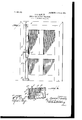
- Figure l is an elevation showing the invention applied to a door
- Fig. 2 a detail perspective of the operatingbolt for the mechanism.
- the letter A designates a door or other similar structure to which the bolts or locking mechanism B may be applied and coperate with a suitable keeper B upon the frame A of the door.
- These bolts B are of any preferred construction in common use, but preferably spring-actuated, and the bolt at the top of the door is connected with the operating-bolt at thebottom of the door by means of a chain or other suitable connection B2, extending therefrom to a rod C, carried by the lever C2 of the bolt C, whichbolt is pivotally mounted at C3 within any suitable form of casing C4.
- the bolt B at the side of the door is connected with the chain B2 by means of a supplemental chain B3, passing over a pulley B4 and connected at B5 with the main chain B2.
- the object of this supplemental chain is to secure a direct pull in releasing the bolt B at the side of the door.
- the bolt C is normally thrown downward into contact with the floor or a suitable aperture therein by means of a tension-spring C5, which surrounds the post C, carried by the lower bolt, and is disposed between the casing and the upper face of the bolt.
- the bolt is provided beyond its pivot with a latch-plate C7, pivotally mounted at C8 in the free end of the bolt and adapted to oscillate laterally of the bolt in order to engage notches or recesses'C, formed in an end wall C10 of the casing C, these notches or recesses being connected by a slot to permit a downward movement of the lever end of the bolt C when the latch-plate C7 is in alinement with the slot.
- a pivoted angular operating-bolt provided with a lever at one side thereof, a locking-bolt removed from said operating-bolt, a rod extending from said lever, a connection extending from the locking-bolt to the rod upon the lever of the pivoted bolt, a fixed plate, and a pivoted latch-plate carried by the lever end of the operating-bolt to engage said fixed plate.
- an angular operating-bolt pivoted intermediate of its ends, a casing within which said bolt is disposed, a post disposed upon said bolt at one side of its pivot, a spring surrounding IOO IIO
Landscapes
- Lock And Its Accessories (AREA)
Description
' QPATENTBD JAN. 2, 1906. s..s. HAWLEY.
MULTIPLE BOLT MEGHA-NISM.
Y B', A. l 5. ff L if o Y lv MINIMUM 0 UMH.
WIT/V55 5:
JNVENOR UNITED sTATns PATENT OFFICE.
Specification of Letters Patent.
Patented Jan. 2, 1906.
Application filed April 5, 1905. Serial No. 253,942.
T0 a/ZZ whom it may concern;
Be it known that I, SYLVEsTER S. HAWLEY, a citizen of the United States, residing at Centralia, in the county of Marion, State of Illinois, have invented Certain new and useful Improvements -in Multiple-Bolt Mechanism, of which the following is a specification, reference being had therein to the accompanying drawings.
This invention relatesto amultiple-boltoperating mechanism, and particularly to a construction whereby a plurality of springactuated bolts or latches are simultaneously operated by a movement of one of them.
The invention has for an object to provide an improved construction and arrangement of the parts by which in the operation of a bolt other latches or bolts disposed at different points may be simultaneously moved and the operating-bolt secured and held in its adjusted position.
Other and further objects and advantages of the invention will be hereinafter set forth and the novel features thereof defined by the appended claims.
In the drawings, Figure l is an elevation showing the invention applied to a door, and
Fig. 2 a detail perspective of the operatingbolt for the mechanism.
Like letters of reference refer to like parts in both figures of the drawings.
The letter A designates a door or other similar structure to which the bolts or locking mechanism B may be applied and coperate witha suitable keeper B upon the frame A of the door. These bolts B are of any preferred construction in common use, but preferably spring-actuated, and the bolt at the top of the door is connected with the operating-bolt at thebottom of the door by means of a chain or other suitable connection B2, extending therefrom to a rod C, carried by the lever C2 of the bolt C, whichbolt is pivotally mounted at C3 within any suitable form of casing C4. The bolt B at the side of the door is connected with the chain B2 by means of a supplemental chain B3, passing over a pulley B4 and connected at B5 with the main chain B2. The object of this supplemental chain is to secure a direct pull in releasing the bolt B at the side of the door.
The bolt C is normally thrown downward into contact with the floor or a suitable aperture therein by means of a tension-spring C5, which surrounds the post C, carried by the lower bolt, and is disposed between the casing and the upper face of the bolt. The bolt is provided beyond its pivot with a latch-plate C7, pivotally mounted at C8 in the free end of the bolt and adapted to oscillate laterally of the bolt in order to engage notches or recesses'C, formed in an end wall C10 of the casing C, these notches or recesses being connected by a slot to permit a downward movement of the lever end of the bolt C when the latch-plate C7 is in alinement with the slot.
In the operation of the invention it will be seen that all of the bolts will be released when the latch-plate carried by the lower bolt is depressed and its spring placed under tension, in which position it may be retained by a lateral movement of the latch-plate in the engagement with the lower notch carried by the casing. The door is now free to be opened and may be held in a partially-opened position by releasing the latch-plate, so that the bolt C will be thrown downward to frictionallyengage the floor. When the door is closed, with the parts in these positions, the several bolts engage their proper sockets, and the door is thus held, while any operation of the lower bolt by tension upon the connecting means may be obviated by engaging .the
latch-plate with the upper recessin its casing, as shown by full lines in Fig. 2. It will thus be seen that the lower bolt embodies means for simultaneously operating those connected therewith and for holding them in their locked or unlocked position.
It will be obvious that changes may be made in the details of construction and configuration without departing from the spirit of the invention as defined by the appended claims.
Having described my invention and set forth its Inerits, what I claim, and desire to secure by Letters Patent, is
1. In a device of the class described, a pivoted angular operating-bolt provided with a lever at one side thereof, a locking-bolt removed from said operating-bolt, a rod extending from said lever, a connection extending from the locking-bolt to the rod upon the lever of the pivoted bolt, a fixed plate, and a pivoted latch-plate carried by the lever end of the operating-bolt to engage said fixed plate.
2. In a device of the class described, an angular operating-bolt pivoted intermediate of its ends, a casing within which said bolt is disposed, a post disposed upon said bolt at one side of its pivot, a spring surrounding IOO IIO
to engage a `fixed plate, a connecting-rod eX- tending from the lever end of said b olt through said casing, a bolt disposed at a distance therefrom, and a flexible connection between said rod and locking-bolt.
' In testimony whereof I my signature in presence of two witnesses.
SYLVESTER S. HAWLEY.
Witnesses:
' lnoMAs MILES, Jos. H. FYKE.
Priority Applications (1)
| Application Number | Priority Date | Filing Date | Title |
|---|---|---|---|
| US1905253942 US809184A (en) | 1905-04-05 | 1905-04-05 | Multiple-bolt mechanism. |
Applications Claiming Priority (1)
| Application Number | Priority Date | Filing Date | Title |
|---|---|---|---|
| US1905253942 US809184A (en) | 1905-04-05 | 1905-04-05 | Multiple-bolt mechanism. |
Publications (1)
| Publication Number | Publication Date |
|---|---|
| US809184A true US809184A (en) | 1906-01-02 |
Family
ID=2877665
Family Applications (1)
| Application Number | Title | Priority Date | Filing Date |
|---|---|---|---|
| US1905253942 Expired - Lifetime US809184A (en) | 1905-04-05 | 1905-04-05 | Multiple-bolt mechanism. |
Country Status (1)
| Country | Link |
|---|---|
| US (1) | US809184A (en) |
-
1905
- 1905-04-05 US US1905253942 patent/US809184A/en not_active Expired - Lifetime
Similar Documents
| Publication | Publication Date | Title |
|---|---|---|
| US809184A (en) | Multiple-bolt mechanism. | |
| US595505A (en) | Door-fastener | |
| US833024A (en) | Door-check. | |
| US559296A (en) | Gate-latch | |
| US988114A (en) | Sash-lock. | |
| US703252A (en) | Window attachment. | |
| US589811A (en) | Blind-fastener | |
| US469863A (en) | John marks | |
| US1033151A (en) | Emergency-exit-door lock. | |
| US543506A (en) | Door lock and latch | |
| US1067241A (en) | Safety door-bolt. | |
| US579852A (en) | Latch | |
| US1074750A (en) | Latch. | |
| US187698A (en) | Improvement in door-latches | |
| US825690A (en) | Gate-latch. | |
| US431845A (en) | Island | |
| US894571A (en) | Sash-lock. | |
| US1061878A (en) | Door-latch. | |
| US851299A (en) | Sash-lock. | |
| US196662A (en) | Improvement in fasteners for meeting-rails of sashes | |
| US973225A (en) | Door-lock. | |
| US341152A (en) | Sash-fastener | |
| US761580A (en) | Farm-gate. | |
| US1124278A (en) | Latch. | |
| US838701A (en) | Door-latch. |