US8091241B2 - Electric hair remover - Google Patents
Electric hair remover Download PDFInfo
- Publication number
- US8091241B2 US8091241B2 US12/277,485 US27748508A US8091241B2 US 8091241 B2 US8091241 B2 US 8091241B2 US 27748508 A US27748508 A US 27748508A US 8091241 B2 US8091241 B2 US 8091241B2
- Authority
- US
- United States
- Prior art keywords
- body part
- holder
- electric hair
- holder part
- hair remover
- Prior art date
- Legal status (The legal status is an assumption and is not a legal conclusion. Google has not performed a legal analysis and makes no representation as to the accuracy of the status listed.)
- Expired - Fee Related, expires
Links
Images


Classifications
-
- B—PERFORMING OPERATIONS; TRANSPORTING
- B26—HAND CUTTING TOOLS; CUTTING; SEVERING
- B26B—HAND-HELD CUTTING TOOLS NOT OTHERWISE PROVIDED FOR
- B26B19/00—Clippers or shavers operating with a plurality of cutting edges, e.g. hair clippers, dry shavers
- B26B19/38—Details of, or accessories for, hair clippers, or dry shavers, e.g. housings, casings, grips, guards
- B26B19/3806—Accessories
- B26B19/382—Built-in accessories
-
- B—PERFORMING OPERATIONS; TRANSPORTING
- B26—HAND CUTTING TOOLS; CUTTING; SEVERING
- B26B—HAND-HELD CUTTING TOOLS NOT OTHERWISE PROVIDED FOR
- B26B19/00—Clippers or shavers operating with a plurality of cutting edges, e.g. hair clippers, dry shavers
- B26B19/38—Details of, or accessories for, hair clippers, or dry shavers, e.g. housings, casings, grips, guards
- B26B19/3853—Housing or handle
Definitions
- the present invention relates to an electric hair remover (epilator) for removing hair.
- an electric hair remover such as electric razor has such a structure that a blade block for cutting hair is disposed at a head end of a body part which also serves as a holder part.
- a motor for driving the blade, a driver for transmitting the driving force of the motor and a battery block for driving the motor, and the like are received in the body part.
- a switch drives the motor, thereby moving the blade for removing hair.
- JP2007105077 discloses a manual safety razor (referred to as “T-shaped trimmer for shaving eyebrows”) which has such a structure that a body part is made bendable or telescopic. As such, the razor has a convenient configuration during operation by the user while the razor is made compact for storage (put in a receptacle) after the operation.
- the above conventional electric hair remover For receiving the motor, driver, battery block and the like in the body part, the above conventional electric hair remover, however, has difficulty in making the body part telescopic which also serves as a holder part. In other words, the body part of the conventional electric hair remover is fixed at a relatively short length, making it difficult to remove hair which is beyond the reach of hand or hard to reach.
- an electric hair remover comprises: a body part having a head end part in a longitudinal direction, a blade part for cutting hair being formed at the head end part; a holder part mounted to the body part in such a configuration as to slide along the longitudinal direction of the body part and to rotate.
- FIG. 1 is a front view of an electric hair remover, according to an embodiment of the present invention.
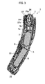
- FIG. 2 is a side view of the electric hair remover, according to the embodiment of the present invention.
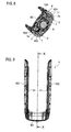
- FIG. 3 is a cross sectional view taken along the line III-III in FIG. 1 .
- FIG. 4 is a front view of the electric hair remover, with a holder part and a front cover removed, according to the embodiment of the present invention.
- FIG. 5 is a side view of the electric hair remover, with the holder part and front cover removed, according to the embodiment of the present invention.
- FIG. 6 is a front view of the electric hair remover, with the holder part most pulled out, according to the embodiment of the present invention.
- FIG. 7 is a side view of the electric hair remover, with the holder part most pulled out, according to the embodiment of the present invention.
- FIG. 8 is a cross sectional view taken along the line VIII-VIII in FIG. 7 .
- FIG. 9 is a front view of the holder part of the electric hair remover, according to the embodiment of the present invention.
- FIG. 10 is a cross sectional view taken along the line X-X in FIG. 9 .
- FIG. 11 is a cross sectional view of an angle adjuster of the electric hair remover, according to the embodiment of the present invention.
- FIG. 12 is a perspective view of the electric hair remover, with the holder part most rotated, according to the embodiment of the present invention.
- FIG. 13 is a side view of the electric hair remover, with the holder part most rotated, according to the embodiment of the present invention.
- FIG. 14 is a side view showing that a load relief part of the electric hair remover is in operation, according to the embodiment of the present invention.
- FIG. 15 is a side view of an angle adjuster when the load relief part of the electric hair remover is in operation, according to the embodiment of the present invention.
- FIG. 1 to FIG. 15 show an electric hair remover, according to an embodiment of the present invention.
- FIG. 1 is a front view of the electric hair remover.
- FIG. 2 is a side view of the electric hair remover.
- FIG. 3 is a cross sectional view taken along the line III-III in FIG. 1 .
- FIG. 4 is a front view of the electric hair remover, with a holder part and a front cover removed.
- FIG. 5 is a side view of the electric hair remover, with the holder part and front cover removed.
- FIG. 6 is a front view of the electric hair remover, with the holder part most pulled out.
- FIG. 7 is a side view of the electric hair remover, with the holder part most pulled out.
- FIG. 8 is a cross sectional view taken along the line VIII-VIII in FIG. 7 .
- FIG. 9 is a front view of the holder part of the electric hair remover.
- FIG. 10 is a cross sectional view taken along the line X-X in FIG. 9 .
- FIG. 11 is a cross sectional view of an angle adjuster of the electric hair remover.
- FIG. 12 is a perspective view of the electric hair remover, with the holder part most rotated.
- FIG. 13 is a side view of the electric hair remover, with the holder part most rotated.
- FIG. 14 is a side view showing that a load relief part of the electric hair remover is in operation.
- FIG. 15 is a side view of an angle adjuster when the load relief part of the electric hair remover is in operation.
- an electric hair remover 1 (epilator) according to an embodiment includes a body part 3 having such a structure that a blade block 2 as a blade part for cutting hair is disposed at a head end 3 e along a longitudinal direction (upper-lower direction in FIG. 1 and FIG. 2 ).
- the body part 3 is gently curved along an arc having substantially a constant radius, as shown in FIG. 2 .
- portions of a holder part 4 on respective right and left sides of the body part 3 are each curved.
- a radial inner side of the curved body part 3 is defined as front side while a radial outer side of the body part 3 is defined as back side.
- the blade block 2 has a comb-shaped trimmer blade 2 T for cutting a long hair and a net blade 2 N for finishing the hair shortened by the trimmer blade 2 T.
- the net blade 2 N fixedly protrudes at a head end of the blade block 2 .
- upward-downward operations of a trimmer handle 2 H disposed on the front side of the blade block 2 allow the trimmer blade 2 T to protrude (upward) from and subside (downward) in the head end of the blade block 2 .
- the body part 3 includes a motor 5 for driving the trimmer blade 2 T and net blade 2 N.
- a driver 5 b is mounted via an eccentric cam 5 a in such a state that the driver 5 b is eccentric. It is so structured that rotation of the motor 5 is converted into reciprocation of the driver 5 b .
- the body part 3 includes a battery block B for driving the motor 5 .
- an inner blade 2 Na of the net blade 2 N is mounted to a head end of the driver 5 b , and the inner blade 2 Na sliding with is configured to cut hair. Furthermore, a trimmer driver 2 Ta for transmitting the driving force to the trimmer blade 2 T is disposed on the way of the driver 5 b.
- a switch handle 6 is disposed substantially in the center on the front side of the body part 3 . Being hooked with a hook (not shown) of a front cover 3 C of the body part 3 , the switch handle 6 makes reciprocation in the longitudinal direction, thereby switching open-and-close of a circuit for driving the motor 5 . As such, the switch handle 6 serves as an operator for switching ons-and-offs (i.e., on-operation and off-operation) of a power source.
- the electric hair remover 1 has the holder part 4 which is a member separated from the body part 3 .
- the holder part 4 is mounted to the body part 3 in such a configuration as to be telescopically slidable relative to the body part 3 along the longitudinal direction and to make a rotation relative to the body part 3 .
- the holder part 4 includes a left part 4 S 1 , a right part 4 S 2 and a connector part 4 C which are combined to be shaped substantially into an alphabetical U extending along an outer periphery of the body part 3 .
- the left part 4 S 1 and right part 4 S 2 extend on respective left and right sides in the lateral direction of the body part 3 in front view while the connector part 4 C connects head end sides (in the pull-out direction) of the respective left and right parts 4 S 1 , 4 S 2 .
- rotation bases 9 each configured to make a rotation around a slide lock button 7 are disposed on both sides of a base part 3 B in the lower part of the body part 3 .
- a rail groove 10 is formed for allowing the holder part 4 to slide on the rail groove 10 .
- the rotation base 9 has a rail groove 10 A on an extension of the rail groove 10 .
- a rail 11 slidably engaged with the rail grooves 10 , 10 A is formed on an inner face of each of the left and right parts 4 S 1 , 4 S 2 of the holder part 4 , where FIG. 10 shows the left part 4 S 1 .
- Inserting the rails 11 into the rail grooves 10 , 10 A allows the portions of the holder parts 4 to be disposed on both sides of the body part 3 , as shown in FIG. 1 and FIG. 2 . Then, sliding the rails 11 along the rail grooves 10 , 10 A allows the holder part 4 to move along the longitudinal direction of the body part 3 .
- FIG. 1 and FIG. 2 show a shrunk state of the combination while FIG. 6 and FIG. 7 show an extended state of the combination.
- a plurality of rail dent parts 11 a , 11 b , 11 c each disengageably mated with the slide lock button 7 are disposed at certain intervals in the longitudinal direction.
- an inner face of the slide lock button 7 is formed with a coil spring 7 a which is so set as to continuously press (bias) the slide lock button 7 outward.
- a head end of the slide lock button 7 is caused to continuously protrude through a hole formed in the rail groove 10 A disposed on the rotation base 9 .
- a head end protrusion part 7 b of the slide lock button 7 is so configured to be sequentially mated with the rail dent parts 11 a , 11 b , 11 c according to sliding positions of the holder part 4 .
- the head end protrusion part 7 b of the slide lock button 7 is brought into such a state as to be mated with the rail dent part 11 a .
- pulling the holder part 4 in the extended direction disengages the head end protrusion part 7 b from the rail dent part 11 a , thus allowing the holder part 4 to slide with the head end protrusion part 7 b pressed in.
- the biasing force of the coil spring 7 a allows the head end protrusion part 7 b of the slide lock button 7 to protrude and thereby to engage with the rail dent part 11 b , thus fixing the holder part 4 .
- the head end protrusion part 7 b of the slide lock button 7 is mated with the rail dent part 11 c , thus fixing the holder part 4 .
- the rail 11 is mated with both of the rail groove 10 on the body part 3 side and the rail groove 10 A on the rotation base 9 side. As shown in FIG. 6 and FIG. 7 , however, with the body part 3 and holder part 4 most extended (i.e., the holder part 4 most pulled out of the body part 3 ), that is, when the slide lock button 7 is engaged with the rail dent part 11 c , the rail 11 is removed from the rail groove 10 and mates only with the rail groove 10 A.
- the rotation base 9 is allowed to make a rotation only when the body part 3 and holder part 4 are most extended.
- the body part 3 can be so bent relative to the holder part 4 as to form substantially an alphabetical V in combination with the holder part 4 .
- a rotation center brought about in this state is referred to as a rotation axis Ax in FIG. 12 and FIG. 13 .
- the rotation base 9 as a rotation part of the holder part 4 has an angle adjuster 12 for accomplishing multi-step rotational fixations within the rational area of the holder part 4 .
- the angle adjuster 12 includes a click gear 13 and a plate-spring click plate 14 , where the click gear 13 is integrally rotatable with the rotation base 9 and has an outer periphery formed with a gear-shaped irregular part 13 a while the click plate 14 is disposed on the body part 3 side and adds a rotational resistance to the irregular part 13 a of the click gear 13 .
- a protrusion part 14 a engageable with a dent of the irregular part 13 a of the click gear 13 is formed in substantially the center part of the click plate 14 .
- the protrusion part 14 a engaged with one of the dents of the irregular part 13 a can prevent the rotation of the rotation base 9 by means of a certain resistance force.
- the irregular part 13 a is formed corresponding to the allowable rotational area of the holder part 4 .
- First and second stepped parts 13 b , 13 c formed on respective sides of the irregular part 13 a of the click gear 13 are configured to abut on respective first and second stopper parts 3 p 1 , 3 p 2 formed on the body part 3 side, thus stopping the rotation of the holder part 4 to thereby prevent further rotation of the holder part 4 .
- the body part 3 is gently curved in the longitudinal direction.
- the angle adjuster 12 of the rotation base 9 has a load relief part 15 .
- the load relief part 15 is so set as to make the following operation:
- the load relief part 15 relieves, corresponding to a certain load or over applied to the rotation base 9 , the body part 3 from the holder part 4 in the direction for opening (see FIG. 14 ).
- the load relief part 15 is, as shown in FIG. 11 , set by cutting away the irregular part 13 a of the click gear 13 in a certain range. That is, in the following range, the load relief part 15 is formed by cutting away the irregular part 13 a which corresponds to the protrusion part 14 a of the click plate 14 :
- the holder part 4 is made free. Then, as shown in FIG. 15 , the holder part 4 is allowed to be bent without resistance until the second stepped part 13 c of the click gear 13 abuts on the second body part 3 p 2 .
- the load relief part 15 provided for the rotation base 9 works to allow the body part 3 and holder part 4 to open in a form of a reversed bending, as shown in FIG. 14 .
- an edge part of the base part 3 B of the body part 3 contacts the flat base and thereby can receive the load.
- a substantially flat mounting face 3 F is formed on a surface of the base part 3 B.
- the base part 3 B is disposed on a side opposite to a side of the head end part (for providing the blade block 2 ) of the body part 3 .
- a single point of a part spaced apart from the rotation axis Ax of the holder part 4 is disposed on an extended face E along the mounting face 3 F.
- the single point is defined as a contact part 4 P.
- the head end part 4 T of the holder part 4 is disposed on the extended face E of the mounting face 3 F.
- the electric hair remover 1 can be disposed in such a state that the holder part 4 is most rotated for use while the body part 3 is standing on the flat face as the pedestal.
- the holder part 4 having the left and right parts 4 S 1 , 4 S 2 and the connector part 4 C is formed substantially into an alphabetical U.
- the user In a shower room and the like, the user, as the case may be, removes hair in a standing state.
- the user for checking the finished state after clearing (or dusting) off the hair which was adhered to the body, the user is supposed to once release the electric hair remover 1 from hand.
- hooking the pulled-out holder part 4 (set forth above) with a protrusion such as hook can rapidly restart the hair-removing operation without leaving the electric hair remover 1 on the floor or the like.
- the holder part 4 which is a member separated from the body part 3 is telescopically slidable relative to the body part 3 in the longitudinal direction and rotatable relative to the body part 3 .
- the blade block 2 at the head end of the electric hair remover 1 of the present invention can easily abut on tiptoes, calf, back and the like on which the conventional fixed-type counterpart fails to easily abut.
- rotating the holder part 4 in its elongated state allows the blade block 2 to abut on a portion far away from hand, such as back.
- the holder part 4 's rotation relative to the body part 3 is allowed only when the combination of the body part 3 and the holder part 4 is most elongated.
- the holder part 4 's angle relative to the body part 3 can be set variable.
- the above structure of the electric hair remover 1 allows the blade block 2 to abut on the user's back and the like which is a portion far away from hand.
- the above structure of the electric hair remover 1 can prevent such a failure that the holder part 4 is moved relative to the body part 3 when the electric hair remover 1 is being used by the user, which is an advantage.
- the angle adjuster 12 is capable of engaging the body part 3 with the holder part 4 for fixation at multi-step angles.
- the relative angles can be set variable at multiple steps, thus more improving usability of the electric hair remover 1 .
- the electric hair remover 1 can be set more usable and convenient.
- the load is applied to the body part 3 and holder part 4 in the direction of relative rotation, thereby elastically deforming at least a part (click plate 14 ) between the rotation axis Ax (of the relative rotation) and the mutual engagement part.
- the engagement state by means of the angle adjuster 12 can be disengaged in the direction for opening the body part 3 relative to the holder part 4 .
- the combination of the body part 3 and holder part 4 is curved along the longitudinal direction to form substantially an arch and the load relief part 15 set at the rotation base 9 disposed substantially in the center part of the longitudinal direction works for allowing a reversed-bending relative rotation between the body part 3 and the holder part 4 .
- the substantially flat mounting face 3 F is formed on the surface of the base part 3 B, as shown in FIG. 13 .
- the base part 3 B is disposed on the side opposite to the side of the head end part 3 e of the body part 3 .
- a surface of a part (the head end part 4 T of the holder part 4 , according to the embodiment) which is spaced apart from the rotation axis Ax is disposed on the extended face E along the mounting face 3 F.
- the surface of the above part is defined as a contact part 4 P.
- the mounting face 3 F and contact part 4 P are caused to have a contact with a flat face as a pedestal, and thereby the body part 3 is allowed to stand on the flat face, with the blade block 2 positioned upper.
- the electric hair remover 1 can be disposed on the flat face, thus further improving usability of the electric hair remover 1 .
- the holder part 4 includes the left part 4 S 1 , right part 4 S 2 and connector part 4 C which are combined to be shaped substantially into an alphabetical U extending along an outer periphery of the body part 3 .
- the left part 4 S 1 and right part 4 S 2 are disposed on respective left and right sides in the lateral direction of the body part 3 substantially perpendicular to the longitudinal direction of the body part 3 while the connector part 4 C connects head end sides (in the pull-out direction) of the respective left and right parts 4 S 1 , 4 S 2 .
- the holder part 4 's U-shaped part can be used as a hook, thus further improving usability of the electric hair remover 1 .
- each of the mounting face 3 F and the contact part 4 P may be properly changed.
- trimmer blade 2 T and net blade 2 N are disposed at the blade block 2 , but not limited thereto.
- a single blade or other blade(s) may be provided for the blade block 2 .
Landscapes
- Life Sciences & Earth Sciences (AREA)
- Forests & Forestry (AREA)
- Engineering & Computer Science (AREA)
- Mechanical Engineering (AREA)
- Dry Shavers And Clippers (AREA)
- Cosmetics (AREA)
Applications Claiming Priority (2)
| Application Number | Priority Date | Filing Date | Title |
|---|---|---|---|
| JP2007-332622 | 2007-12-25 | ||
| JP2007332622A JP4613948B2 (ja) | 2007-12-25 | 2007-12-25 | 電動除毛器 |
Publications (2)
| Publication Number | Publication Date |
|---|---|
| US20090163932A1 US20090163932A1 (en) | 2009-06-25 |
| US8091241B2 true US8091241B2 (en) | 2012-01-10 |
Family
ID=40467024
Family Applications (1)
| Application Number | Title | Priority Date | Filing Date |
|---|---|---|---|
| US12/277,485 Expired - Fee Related US8091241B2 (en) | 2007-12-25 | 2008-11-25 | Electric hair remover |
Country Status (7)
| Country | Link |
|---|---|
| US (1) | US8091241B2 (de) |
| EP (1) | EP2075102B1 (de) |
| JP (1) | JP4613948B2 (de) |
| CN (1) | CN101468470B (de) |
| AT (1) | ATE496741T1 (de) |
| DE (1) | DE602008004725D1 (de) |
| RU (1) | RU2008150323A (de) |
Cited By (10)
| Publication number | Priority date | Publication date | Assignee | Title |
|---|---|---|---|---|
| US9718200B2 (en) | 2014-01-31 | 2017-08-01 | Dryfhout Enterprises, Llc | Safety razor with comb and integrated blade and associated methods |
| US9937629B1 (en) | 2016-05-17 | 2018-04-10 | Dryfhout Enterprises, Llc | Two-point discrimination safety razor assembly |
| US10131062B1 (en) | 2014-01-31 | 2018-11-20 | Dryfhout Enterprises, Llc | Body shaver with comb and blade |
| US10315322B1 (en) | 2016-05-17 | 2019-06-11 | Dryfhout Properties, Llc | Method of using a back shaver handle |
| US10493643B1 (en) | 2016-05-17 | 2019-12-03 | Dryfhout Properties, Llc | Leveled back shaver |
| US10500744B1 (en) | 2014-01-31 | 2019-12-10 | Dryfhout Properties, Llc | Safety razor with plurality of comb and integrated blade groups |
| US10543609B2 (en) | 2016-05-17 | 2020-01-28 | Dryfhout Properties, Llc | Elevated shaver |
| US11077570B2 (en) | 2014-01-31 | 2021-08-03 | Dryfhout Properties, Llc | Flexible back shaver |
| US11351685B2 (en) * | 2017-11-10 | 2022-06-07 | Spectrum Brands, Inc. | Hair grooming appliance |
| US12280512B2 (en) | 2014-01-31 | 2025-04-22 | Bakblade Limited | Safety razor with comb and blade |
Families Citing this family (4)
| Publication number | Priority date | Publication date | Assignee | Title |
|---|---|---|---|---|
| JP5572048B2 (ja) * | 2010-09-27 | 2014-08-13 | パナソニック株式会社 | ヘアカッター |
| US10414058B2 (en) | 2016-08-11 | 2019-09-17 | The Gillette Company Llc | Handle for a razor |
| EP4674582A1 (de) | 2024-07-02 | 2026-01-07 | Koninklijke Philips N.V. | Griffverlängerung und haarschneideanordnung |
| EP4699755A1 (de) | 2024-08-23 | 2026-02-25 | Koninklijke Philips N.V. | Zubehörkomponente und pflegegerät |
Citations (16)
| Publication number | Priority date | Publication date | Assignee | Title |
|---|---|---|---|---|
| US4188717A (en) * | 1977-10-19 | 1980-02-19 | Mansfield Henry T | Apparatus aid |
| JPS6091176A (ja) * | 1983-10-25 | 1985-05-22 | 日新興業株式会社 | 船舶用コンタクトフリーザーの荷役合理化装置 |
| US4521962A (en) | 1984-02-27 | 1985-06-11 | Harold Van Natta | Grooming device |
| JPS61103472A (ja) | 1984-10-25 | 1986-05-21 | 泉精密工業株式会社 | レシプロ型電気かみそり |
| US5193528A (en) * | 1990-01-13 | 1993-03-16 | Matsushita Electric Works, Ltd. | Hand-held vibratory massager |
| US6189222B1 (en) * | 1999-10-15 | 2001-02-20 | Calvin M. Doyle | Articulated razor handle extension |
| US20040107585A1 (en) | 2002-12-09 | 2004-06-10 | Helmrich Christopher M. | Shaver extension arm assembly and method |
| CA2443881A1 (en) | 2003-10-02 | 2005-04-02 | Jean Kelly | Shaver assembly with radial rotation and axial pivoting head and telescopic handle |
| US20050229398A1 (en) | 2004-04-15 | 2005-10-20 | Leventhal James M | Integrated shaver and hair trimmer device with adjustable handle |
| US20070044320A1 (en) | 2005-08-26 | 2007-03-01 | Matsushita Electric Works, Ltd. | Hair clipper |
| JP2007105077A (ja) | 2005-10-11 | 2007-04-26 | Nikken Kamisori Kk | 眉剃り用t型カミソリ |
| US20070261249A1 (en) * | 2004-12-16 | 2007-11-15 | Matsushita Electric Works, Ltd. | Hair Removing Apparatus |
| US20070289144A1 (en) | 2006-06-16 | 2007-12-20 | Matsushita Electric Works, Ltd. | Hair clipper |
| US20080208190A1 (en) | 2007-02-23 | 2008-08-28 | Matsushita Electric Works, Ltd. | Hair removal apparatus |
| US20080294176A1 (en) | 2007-02-23 | 2008-11-27 | Matsushita Electric Works, Ltd. | Hair removal apparatus |
| US20110088268A1 (en) * | 2005-09-21 | 2011-04-21 | Marut Brett C | Razor with articulated handle extension |
Family Cites Families (1)
| Publication number | Priority date | Publication date | Assignee | Title |
|---|---|---|---|---|
| JPS6091176U (ja) * | 1983-11-28 | 1985-06-21 | 東芝テック株式会社 | 電気かみそり |
-
2007
- 2007-12-25 JP JP2007332622A patent/JP4613948B2/ja not_active Expired - Fee Related
-
2008
- 2008-11-25 US US12/277,485 patent/US8091241B2/en not_active Expired - Fee Related
- 2008-12-01 AT AT08020848T patent/ATE496741T1/de not_active IP Right Cessation
- 2008-12-01 EP EP08020848A patent/EP2075102B1/de not_active Not-in-force
- 2008-12-01 DE DE602008004725T patent/DE602008004725D1/de active Active
- 2008-12-18 CN CN2008101852272A patent/CN101468470B/zh not_active Expired - Fee Related
- 2008-12-18 RU RU2008150323/02A patent/RU2008150323A/ru not_active Application Discontinuation
Patent Citations (16)
| Publication number | Priority date | Publication date | Assignee | Title |
|---|---|---|---|---|
| US4188717A (en) * | 1977-10-19 | 1980-02-19 | Mansfield Henry T | Apparatus aid |
| JPS6091176A (ja) * | 1983-10-25 | 1985-05-22 | 日新興業株式会社 | 船舶用コンタクトフリーザーの荷役合理化装置 |
| US4521962A (en) | 1984-02-27 | 1985-06-11 | Harold Van Natta | Grooming device |
| JPS61103472A (ja) | 1984-10-25 | 1986-05-21 | 泉精密工業株式会社 | レシプロ型電気かみそり |
| US5193528A (en) * | 1990-01-13 | 1993-03-16 | Matsushita Electric Works, Ltd. | Hand-held vibratory massager |
| US6189222B1 (en) * | 1999-10-15 | 2001-02-20 | Calvin M. Doyle | Articulated razor handle extension |
| US20040107585A1 (en) | 2002-12-09 | 2004-06-10 | Helmrich Christopher M. | Shaver extension arm assembly and method |
| CA2443881A1 (en) | 2003-10-02 | 2005-04-02 | Jean Kelly | Shaver assembly with radial rotation and axial pivoting head and telescopic handle |
| US20050229398A1 (en) | 2004-04-15 | 2005-10-20 | Leventhal James M | Integrated shaver and hair trimmer device with adjustable handle |
| US20070261249A1 (en) * | 2004-12-16 | 2007-11-15 | Matsushita Electric Works, Ltd. | Hair Removing Apparatus |
| US20070044320A1 (en) | 2005-08-26 | 2007-03-01 | Matsushita Electric Works, Ltd. | Hair clipper |
| US20110088268A1 (en) * | 2005-09-21 | 2011-04-21 | Marut Brett C | Razor with articulated handle extension |
| JP2007105077A (ja) | 2005-10-11 | 2007-04-26 | Nikken Kamisori Kk | 眉剃り用t型カミソリ |
| US20070289144A1 (en) | 2006-06-16 | 2007-12-20 | Matsushita Electric Works, Ltd. | Hair clipper |
| US20080208190A1 (en) | 2007-02-23 | 2008-08-28 | Matsushita Electric Works, Ltd. | Hair removal apparatus |
| US20080294176A1 (en) | 2007-02-23 | 2008-11-27 | Matsushita Electric Works, Ltd. | Hair removal apparatus |
Non-Patent Citations (1)
| Title |
|---|
| English language Abstract of JP 2007-105077, Apr. 26, 2007. |
Cited By (11)
| Publication number | Priority date | Publication date | Assignee | Title |
|---|---|---|---|---|
| US9718200B2 (en) | 2014-01-31 | 2017-08-01 | Dryfhout Enterprises, Llc | Safety razor with comb and integrated blade and associated methods |
| US10131062B1 (en) | 2014-01-31 | 2018-11-20 | Dryfhout Enterprises, Llc | Body shaver with comb and blade |
| US10500744B1 (en) | 2014-01-31 | 2019-12-10 | Dryfhout Properties, Llc | Safety razor with plurality of comb and integrated blade groups |
| US11077570B2 (en) | 2014-01-31 | 2021-08-03 | Dryfhout Properties, Llc | Flexible back shaver |
| US11104018B2 (en) | 2014-01-31 | 2021-08-31 | Dryfhout Properties, Llc | Safety razor with comb and blade |
| US12280512B2 (en) | 2014-01-31 | 2025-04-22 | Bakblade Limited | Safety razor with comb and blade |
| US9937629B1 (en) | 2016-05-17 | 2018-04-10 | Dryfhout Enterprises, Llc | Two-point discrimination safety razor assembly |
| US10315322B1 (en) | 2016-05-17 | 2019-06-11 | Dryfhout Properties, Llc | Method of using a back shaver handle |
| US10493643B1 (en) | 2016-05-17 | 2019-12-03 | Dryfhout Properties, Llc | Leveled back shaver |
| US10543609B2 (en) | 2016-05-17 | 2020-01-28 | Dryfhout Properties, Llc | Elevated shaver |
| US11351685B2 (en) * | 2017-11-10 | 2022-06-07 | Spectrum Brands, Inc. | Hair grooming appliance |
Also Published As
| Publication number | Publication date |
|---|---|
| US20090163932A1 (en) | 2009-06-25 |
| CN101468470B (zh) | 2011-07-20 |
| JP2009153593A (ja) | 2009-07-16 |
| JP4613948B2 (ja) | 2011-01-19 |
| EP2075102B1 (de) | 2011-01-26 |
| CN101468470A (zh) | 2009-07-01 |
| EP2075102A1 (de) | 2009-07-01 |
| ATE496741T1 (de) | 2011-02-15 |
| DE602008004725D1 (de) | 2011-03-10 |
| RU2008150323A (ru) | 2010-06-27 |
Similar Documents
| Publication | Publication Date | Title |
|---|---|---|
| US8091241B2 (en) | Electric hair remover | |
| US20090158596A1 (en) | Electric hair remover | |
| US12145283B2 (en) | Attachment comb and hair cutting appliance | |
| AU2021202402B2 (en) | Multipurpose tool having accessible tool members | |
| US7178244B2 (en) | Powered utility knife | |
| EP2254736B1 (de) | Einen verriegelungsmechanismus enthaltendes werkzeug | |
| JP5612118B2 (ja) | 毛髪をトリミングする装置 | |
| US6862810B2 (en) | Hair-trimmer with releasable cutting head | |
| US20110277326A1 (en) | Manual razor with pivoting shaving head | |
| JP2702760B2 (ja) | 散髪方法 | |
| JP6568418B2 (ja) | 手持ち式の充電式電動工具用の延長ハンドル | |
| CN114474169A (zh) | 一种自带活动式保护罩的刀头结构及毛发修剪器 | |
| CN216577977U (zh) | 一种自带活动式保护罩的刀头结构及毛发修剪器 | |
| CN214561104U (zh) | 一种电推剪推杆调节锁定装置 | |
| EP2815856A1 (de) | Schiebeschaltervorrichtung und Elektrorasierer | |
| JPH1015258A (ja) | 電気かみそり | |
| CN121589879A (zh) | 附件部件和梳理设备 | |
| HK1250502B (en) | Multipurpose tool having accessible tool members | |
| JPH02161979A (ja) | ヘアカッター | |
| HK40024428B (en) | Multipurpose tool having accessible tool members | |
| JPH0547232B2 (de) | ||
| JPS59135089A (ja) | 電気かみそり |
Legal Events
| Date | Code | Title | Description |
|---|---|---|---|
| AS | Assignment |
Owner name: PANASONIC ELECTRIC WORKS CO., LTD.,JAPAN Free format text: ASSIGNMENT OF ASSIGNORS INTEREST;ASSIGNORS:OUCHI, KAZUYUKI;OGAWA, HITOSHI;WANG, WEI;REEL/FRAME:021887/0227 Effective date: 20081031 Owner name: PANASONIC ELECTRIC WORKS CO., LTD., JAPAN Free format text: ASSIGNMENT OF ASSIGNORS INTEREST;ASSIGNORS:OUCHI, KAZUYUKI;OGAWA, HITOSHI;WANG, WEI;REEL/FRAME:021887/0227 Effective date: 20081031 |
|
| FEPP | Fee payment procedure |
Free format text: PAYOR NUMBER ASSIGNED (ORIGINAL EVENT CODE: ASPN); ENTITY STATUS OF PATENT OWNER: LARGE ENTITY |
|
| REMI | Maintenance fee reminder mailed | ||
| LAPS | Lapse for failure to pay maintenance fees | ||
| STCH | Information on status: patent discontinuation |
Free format text: PATENT EXPIRED DUE TO NONPAYMENT OF MAINTENANCE FEES UNDER 37 CFR 1.362 |
|
| STCH | Information on status: patent discontinuation |
Free format text: PATENT EXPIRED DUE TO NONPAYMENT OF MAINTENANCE FEES UNDER 37 CFR 1.362 |
|
| FP | Lapsed due to failure to pay maintenance fee |
Effective date: 20160110 |