US8074686B2 - Tube for transporting high-viscosity materials - Google Patents
Tube for transporting high-viscosity materials Download PDFInfo
- Publication number
- US8074686B2 US8074686B2 US10/542,730 US54273005A US8074686B2 US 8074686 B2 US8074686 B2 US 8074686B2 US 54273005 A US54273005 A US 54273005A US 8074686 B2 US8074686 B2 US 8074686B2
- Authority
- US
- United States
- Prior art keywords
- joint element
- ring sleeve
- transport pipe
- pipe
- inner pipe
- Prior art date
- Legal status (The legal status is an assumption and is not a legal conclusion. Google has not performed a legal analysis and makes no representation as to the accuracy of the status listed.)
- Expired - Fee Related, expires
Links
Images


Classifications
-
- F—MECHANICAL ENGINEERING; LIGHTING; HEATING; WEAPONS; BLASTING
- F16—ENGINEERING ELEMENTS AND UNITS; GENERAL MEASURES FOR PRODUCING AND MAINTAINING EFFECTIVE FUNCTIONING OF MACHINES OR INSTALLATIONS; THERMAL INSULATION IN GENERAL
- F16L—PIPES; JOINTS OR FITTINGS FOR PIPES; SUPPORTS FOR PIPES, CABLES OR PROTECTIVE TUBING; MEANS FOR THERMAL INSULATION IN GENERAL
- F16L23/00—Flanged joints
- F16L23/02—Flanged joints the flanges being connected by members tensioned axially
- F16L23/024—Flanged joints the flanges being connected by members tensioned axially characterised by how the flanges are joined to, or form an extension of, the pipes
-
- B—PERFORMING OPERATIONS; TRANSPORTING
- B65—CONVEYING; PACKING; STORING; HANDLING THIN OR FILAMENTARY MATERIAL
- B65G—TRANSPORT OR STORAGE DEVICES, e.g. CONVEYORS FOR LOADING OR TIPPING, SHOP CONVEYOR SYSTEMS OR PNEUMATIC TUBE CONVEYORS
- B65G53/00—Conveying materials in bulk through troughs, pipes or tubes by floating the materials or by flow of gas, liquid or foam
- B65G53/34—Details
- B65G53/52—Adaptations of pipes or tubes
-
- B—PERFORMING OPERATIONS; TRANSPORTING
- B65—CONVEYING; PACKING; STORING; HANDLING THIN OR FILAMENTARY MATERIAL
- B65G—TRANSPORT OR STORAGE DEVICES, e.g. CONVEYORS FOR LOADING OR TIPPING, SHOP CONVEYOR SYSTEMS OR PNEUMATIC TUBE CONVEYORS
- B65G53/00—Conveying materials in bulk through troughs, pipes or tubes by floating the materials or by flow of gas, liquid or foam
- B65G53/32—Conveying concrete, e.g. for distributing same at building sites
-
- B—PERFORMING OPERATIONS; TRANSPORTING
- B65—CONVEYING; PACKING; STORING; HANDLING THIN OR FILAMENTARY MATERIAL
- B65G—TRANSPORT OR STORAGE DEVICES, e.g. CONVEYORS FOR LOADING OR TIPPING, SHOP CONVEYOR SYSTEMS OR PNEUMATIC TUBE CONVEYORS
- B65G53/00—Conveying materials in bulk through troughs, pipes or tubes by floating the materials or by flow of gas, liquid or foam
- B65G53/34—Details
- B65G53/52—Adaptations of pipes or tubes
- B65G53/523—Wear protection
-
- E—FIXED CONSTRUCTIONS
- E04—BUILDING
- E04G—SCAFFOLDING; FORMS; SHUTTERING; BUILDING IMPLEMENTS OR AIDS, OR THEIR USE; HANDLING BUILDING MATERIALS ON THE SITE; REPAIRING, BREAKING-UP OR OTHER WORK ON EXISTING BUILDINGS
- E04G21/00—Preparing, conveying, or working-up building materials or building elements in situ; Other devices or measures for constructional work
- E04G21/02—Conveying or working-up concrete or similar masses able to be heaped or cast
- E04G21/04—Devices for both conveying and distributing
- E04G21/0418—Devices for both conveying and distributing with distribution hose
-
- F—MECHANICAL ENGINEERING; LIGHTING; HEATING; WEAPONS; BLASTING
- F16—ENGINEERING ELEMENTS AND UNITS; GENERAL MEASURES FOR PRODUCING AND MAINTAINING EFFECTIVE FUNCTIONING OF MACHINES OR INSTALLATIONS; THERMAL INSULATION IN GENERAL
- F16L—PIPES; JOINTS OR FITTINGS FOR PIPES; SUPPORTS FOR PIPES, CABLES OR PROTECTIVE TUBING; MEANS FOR THERMAL INSULATION IN GENERAL
- F16L23/00—Flanged joints
- F16L23/12—Flanged joints specially adapted for particular pipes
-
- F—MECHANICAL ENGINEERING; LIGHTING; HEATING; WEAPONS; BLASTING
- F16—ENGINEERING ELEMENTS AND UNITS; GENERAL MEASURES FOR PRODUCING AND MAINTAINING EFFECTIVE FUNCTIONING OF MACHINES OR INSTALLATIONS; THERMAL INSULATION IN GENERAL
- F16L—PIPES; JOINTS OR FITTINGS FOR PIPES; SUPPORTS FOR PIPES, CABLES OR PROTECTIVE TUBING; MEANS FOR THERMAL INSULATION IN GENERAL
- F16L47/00—Connecting arrangements or other fittings specially adapted to be made of plastics or to be used with pipes made of plastics
- F16L47/20—Connecting arrangements or other fittings specially adapted to be made of plastics or to be used with pipes made of plastics based principally on specific properties of plastics
- F16L47/24—Connecting arrangements or other fittings specially adapted to be made of plastics or to be used with pipes made of plastics based principally on specific properties of plastics for joints between metal and plastics pipes
-
- F—MECHANICAL ENGINEERING; LIGHTING; HEATING; WEAPONS; BLASTING
- F16—ENGINEERING ELEMENTS AND UNITS; GENERAL MEASURES FOR PRODUCING AND MAINTAINING EFFECTIVE FUNCTIONING OF MACHINES OR INSTALLATIONS; THERMAL INSULATION IN GENERAL
- F16L—PIPES; JOINTS OR FITTINGS FOR PIPES; SUPPORTS FOR PIPES, CABLES OR PROTECTIVE TUBING; MEANS FOR THERMAL INSULATION IN GENERAL
- F16L57/00—Protection of pipes or objects of similar shape against external or internal damage or wear
- F16L57/06—Protection of pipes or objects of similar shape against external or internal damage or wear against wear
-
- F—MECHANICAL ENGINEERING; LIGHTING; HEATING; WEAPONS; BLASTING
- F16—ENGINEERING ELEMENTS AND UNITS; GENERAL MEASURES FOR PRODUCING AND MAINTAINING EFFECTIVE FUNCTIONING OF MACHINES OR INSTALLATIONS; THERMAL INSULATION IN GENERAL
- F16L—PIPES; JOINTS OR FITTINGS FOR PIPES; SUPPORTS FOR PIPES, CABLES OR PROTECTIVE TUBING; MEANS FOR THERMAL INSULATION IN GENERAL
- F16L9/00—Rigid pipes
- F16L9/14—Compound tubes, i.e. made of materials not wholly covered by any one of the preceding groups
- F16L9/147—Compound tubes, i.e. made of materials not wholly covered by any one of the preceding groups comprising only layers of metal and plastics with or without reinforcement
-
- F—MECHANICAL ENGINEERING; LIGHTING; HEATING; WEAPONS; BLASTING
- F16—ENGINEERING ELEMENTS AND UNITS; GENERAL MEASURES FOR PRODUCING AND MAINTAINING EFFECTIVE FUNCTIONING OF MACHINES OR INSTALLATIONS; THERMAL INSULATION IN GENERAL
- F16B—DEVICES FOR FASTENING OR SECURING CONSTRUCTIONAL ELEMENTS OR MACHINE PARTS TOGETHER, e.g. NAILS, BOLTS, CIRCLIPS, CLAMPS, CLIPS OR WEDGES; JOINTS OR JOINTING
- F16B7/00—Connections of rods or tubes, e.g. of non-circular section, mutually, including resilient connections
- F16B7/02—Connections of rods or tubes, e.g. of non-circular section, mutually, including resilient connections with conical parts
- F16B7/025—Connections of rods or tubes, e.g. of non-circular section, mutually, including resilient connections with conical parts with the expansion of an element inside the tubes due to axial movement towards a wedge or conical element
-
- F—MECHANICAL ENGINEERING; LIGHTING; HEATING; WEAPONS; BLASTING
- F16—ENGINEERING ELEMENTS AND UNITS; GENERAL MEASURES FOR PRODUCING AND MAINTAINING EFFECTIVE FUNCTIONING OF MACHINES OR INSTALLATIONS; THERMAL INSULATION IN GENERAL
- F16C—SHAFTS; FLEXIBLE SHAFTS; ELEMENTS OR CRANKSHAFT MECHANISMS; ROTARY BODIES OTHER THAN GEARING ELEMENTS; BEARINGS
- F16C2226/00—Joining parts; Fastening; Assembling or mounting parts
- F16C2226/10—Force connections, e.g. clamping
- F16C2226/16—Force connections, e.g. clamping by wedge action, e.g. by tapered or conical parts
-
- F—MECHANICAL ENGINEERING; LIGHTING; HEATING; WEAPONS; BLASTING
- F16—ENGINEERING ELEMENTS AND UNITS; GENERAL MEASURES FOR PRODUCING AND MAINTAINING EFFECTIVE FUNCTIONING OF MACHINES OR INSTALLATIONS; THERMAL INSULATION IN GENERAL
- F16C—SHAFTS; FLEXIBLE SHAFTS; ELEMENTS OR CRANKSHAFT MECHANISMS; ROTARY BODIES OTHER THAN GEARING ELEMENTS; BEARINGS
- F16C2226/00—Joining parts; Fastening; Assembling or mounting parts
- F16C2226/50—Positive connections
- F16C2226/60—Positive connections with threaded parts, e.g. bolt and nut connections
Definitions
- the invention concerns a pipe (tube) for transporting high-viscosity materials, in particular concrete.
- Mobile concrete pumps are frequently employed in the construction industry, wherein concrete is conveyed through transport pipes from a source location to an application location.
- the transport pipes are generally located on the mast arms of a distribution mast, wherein the movement of a terminal hose over a site to be concretized can be directed using remote control.
- stationary concrete pumps in which transport pipes are laid along the ground from the source site to the site of application. Due to the abrasive characteristics of flowing liquid concrete, the transport pipe must be manufactured from an abrasion-resistant material. Conventionally steel pipes are used for this, of which inner surface has been hardened or coated with a abrasion-resistant material.
- the present invention is concerned with the task of developing a pipe for transport of high-viscosity materials, in particular concrete, which is relatively light-weight and nevertheless able to withstand abrasion, and thus is particularly suited for mobile employment.
- the inventive solution is based upon the idea, that by selecting a suitable combination of materials, a pipe with low structural weight can be developed, which nevertheless has a sufficient stability and abrasion resistance for transport of concrete with high bend stiffness.
- a pipe with low structural weight can be developed, which nevertheless has a sufficient stability and abrasion resistance for transport of concrete with high bend stiffness.
- the inventive transport pipes are pairwise joined to each other, with respective collars facing each other, by means of quick release couplings.
- the concrete situated in the transport pipes although it may be able to penetrate into the separation gap between the end faces of two transport pipes joined to each other, however exerts or exercises no sheer forces on the flow between the inner pipe and the ring sleeve, which could lead to a release or peeling away of the inner pipe.
- a slanted or curved transition surface extends in the axial direction away from collar, a which extends to the inner radius of the internally cylindrical ring sleeve, and if the inner surface of the cylindrical inner pipe exhibits an opening bevel or curvature diverging towards the collar, then it is thereby ensured that the flow forces of the inflowing thick material are translated into pressure forces between the inner pipe and the joint element, which counteract a releasing of the inner pipe.
- a further important aspect of the invention is comprised therein that, by a form-fitting engagement between reinforcing jacket and joint element, no undesired changes in length can be caused by axial forces acting on the pipe.
- One particular advantage of the inventive transport pipe is comprised therein that it is exhibits a particularly low structural weight and nevertheless a sufficient bend resistance and pressure stability.
- a sufficient wear resistance with regard to the abrasive viscous materials is achieved when the inner pipe is comprised of a polyurethane with, for example, a Shore A-hardness of 85-95.
- the inner pipe is cast onto the joint element, preferably via an adhesion promoter or primer applied upon the joint element.
- the fiber structure (roving) embedded in the plastic matrix can be joined form-fittingly, in certain cases via an adhesion promoter, with the inner pipe and/or with the joint element.
- the plastic matrix is preferably comprised of a reaction resin from the group consisting of epoxy resin, polyester resin, vinyl resin or a thermoplastic resin. The plastic matrix has the task of supporting the fibers and distributing the forces acting outwardly upon the pipe.
- inventive transport pipes due to their low structural weight, are suitable for employment in mobile or stationary concrete pumps with concrete distribution booms or long transport distances which require a large number of transport pipes.
- inventive transport pipes can, with the same weight, be constructed to be several times longer than the known transport pipes. The handling during the assembly and during laying of the pipes is thereby substantially facilitated.
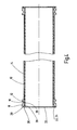
- FIG. 1 a section through a straight transport pipe with various joint elements
- FIG. 2 a curved pipe with the same joint elements
- FIG. 3 an enlarged section of a transport pipe with joint element
- FIG. 4 a section through a straight steel pipe with internal pipe and joint elements welded to the end;
- FIG. 5 a section through a bent pipe of steel with internal pipe and joint elements welded on the ends.
- the composite pipes shown in the figures are intended as transport pipes for viscous materials, in particular for concrete for employment in concrete pumps.
- the transport pipes are comprised essentially of an inner pipe 10 of wear resistant plastic material, for example polyurethane, joint elements 12 provided on the ends, as well as a reinforcing jacket 14 enclosing the inner pipe 10 and joined therewith and with the joint element.
- the ring-shaped joint element comprised of metal, exhibits a collar 16 projecting radially at the end and a ring sleeve 18 joined axially and concentric to the inner pipe 10 .
- a suitable ring clamp pipe connector is placed spanning about two flush contacting collars of transporting pipes, the ring clamp bridging over two collars and the gap from outside to join them to each other, while the ring sleeve 18 ensures a tight and durable joining between joint element 12 and the remaining parts of the transport pipe (inner pipe 10 and reinforcing jacket 14 ).
- a unique feature of the embodiment shown in the figures is comprised in the joining sites shown on the left in FIG. 1 and as shown in FIGS. 2 through 5 between the joint element 12 and the inner pipe 10 .
- the radially projecting collar 16 is there defined by an end face ring surface 20 and a ring step 22 axially recessed from the end face 20 and extending therefrom radially towards the pipe inside, wherein the plastic material of the inner pipe 10 engages from the pipe inside the free area 24 formed by the ring step 22 of the collar.
- the plastic material fills the free area 24 completely and forms an, on the end face 20 of the collar, aligned radially towards inwards connecting end face part 26 .
- the recessed border surface of the step 22 joins, in the axial direction, a slanted or curved transition surface 28 , which extends to the cylindrical inner surface 30 of the ring sleeve. Accordingly, also the inner surface of the cylindrical inner pipe 10 exhibits towards the end face part 26 a trumpet-like diverging opening bevel 32 .
- the mentioned characteristics ensure that the liquid concrete flowing in the coupled transport pipes exerts no sheer forces on the joint location between inner pipe and collar which would lift or peel the inner pipe from the joint element. Any amount of viscous material which penetrates into the separation gap between the end faces 20 of two adjacent transport pipes would be immobile in the area of the separation gap between inner pipe and joint element, so that no wear or lifting forces engage at this location.
- the joint element 12 exhibits on the ring sleeve 18 an axially wave-shaped outer surface 34
- the reinforcing jacket 14 is formed by carbon fiber cable or line (roving) tightly wound in the circumferential direction from the outside and close meshed upon the inner pipe 10 and the wave shaped ring sleeve 18 , and embedded in the plastic matrix.
- the wound carbon fiber line is form-locking and form-fittingly joined with the wave shaped outer surface 34 of the ring sleeve 18 .
- the ring sleeve terminates tapered, so that a shallow transition is enabled for the wound reinforcing jacket 14 (see FIG. 3 ).
- the outer wave contour 38 of the ring sleeve 18 becomes more shallow going towards its free end.
- the sequentially following wave peaks 38 of the wave contour 38 exhibit a decreasing radial height going towards the free end of the ring sleeve 18 .
- a sharp-edged radial returning wave valley 40 to which are joined, going to the free end 36 of the ring sleeve, two wave peaks 38 separated from each other by a further wave valley 42 .
- a further improvement in this respect is achieved thereby, that the inner pipe, in the course of manufacture, is cast onto the joint element 12 , referably via an adhesion promoter or primer applied on the inner surface of the ring sleeve 18 , while the carbon fiber line or cord embedded in the plastic matrix is form fittingly joined with the ring sleeve from the outside and with the inner pipe forming a closed reinforcing jacket.
- the illustrative embodiment shown in FIG. 1 is provided with a wave shaped ring sleeve 18 only on the joint element shown on the left end.
- the joint element 44 shown on the right exhibits no wave structure on its ring sleeve 46 .
- the outside of the cylindrical ring sleeve 46 is adhered with an adhesive layer 48 to the reinforcing jacket 14 of the transport pipe. This manner of construction is necessary in the case when an exact establishment of the pipe length is desired, which can be accomplished thereby, when the joint element 44 is subsequently or later adhered in a defined position on the still open pipe piece.
- the left joint element 12 should be the entry side in a conveyor line, and the right joint element 44 should form the exit side. Only then is it ensured that the inner pipe 10 does not lift or peel from the joint element or from the reinforcing jacket by the viscous medium flowing by.
- joint elements 12 with wave shaped ring sleeve 18 are provided on the two ends.
- the direction of installment or assembly is in this case immaterial.
- the inner pipe 10 exhibits over the circumference a variable wall strength.
- the wall strength is greater than on the inner side.
- the reinforcing jacket 14 is comprised of a pipe or bent pipe of steel.
- the joint elements 12 are there welded with their truncated back bearing ring sleeve 18 on an end of the steel pipe.
- On the inner side of the steel pipe 14 there is an inner pipe 10 of polyurethane forming an inner coating or layer.
- the inlet and outlet sides of the collar 16 and the inner pipe 10 are designed to be similar in the area of the ring step 22 as in the case of the illustrative embodiment according to FIG. 3 .
- the suitable design in the area of the end phase parts 20 , 26 that the liquid concrete flowing by exerts no material lifting sheer forces in the separation location between inner pipe 10 and joint element 12 .
- At least one premanufactured metallic joint part comprising a collar and an externally wave shaped ring sleeve is introduced on one end of a casting mold and there cast with a reaction plastic which is wear resistant in the cured state, with formation of an inner pipe with a collar or flange on one end;
- the finished internal pipe with collar or flange is wound about with a plastic impregnated carbon fiber cord from one end to the other with the formation of the externally wave shaped ring liner and formation of a cohesive reinforcing jacket;
- the finished transport pipe is heated for a period sufficient for curing the plastic matrix and/or for production of a form fitting joint with the inner pipe and the joint element.
- the joint element is coated with an adhesion promoter or primer on its contact surfaces with the inner pipe prior to the casting process.
- the inner pipe and/or the joint element could also be coated with an adhesion promoter or primer on its contact surfaces with the jacket pipe prior to the wrapping process.
- the carbon fiber cord can be wound for example with a multi-axis winding machine with rotation of the inner pipe about the rotation axis. For this, the inner pipe with collar is seated fixed against rotation upon a spindle or winding core, while the winding core is rotated by motor about the axis of the inner pipe.
- the production of the transport pipe occurs with the following steps:
- At least one premanufactured joint element comprising a collar and a ring sleeve, wave shaped on the outside, is wound with a plastic impregnated carbon fiber cord to form a carbon fiber composite pipe;
- reaction plastic is introduced into the carbon fiber composite pipe with its at least one collar, forming an inner coating, and there is cured.
- a core with smaller dimension or diameter can be introduced into the inside of the carbon fiber composite pipe provided with at least one collar, leaving free of a ring gap, wherein the reaction plastic is introduced into the ring gap and is cured there, and subsequently the core is again removed.
- reaction plastic is sprayed upon the inner surface of the adhesion promoter coated carbon fiber composite pipe having at least one collar, or is centrifugally spun on and subsequently is cured to form the finished pipe. In the latter case no core is necessary.
- the invention concerns a transport pipe for high viscosity materials, in particular for concrete.
- the transport pipe includes an inner pipe 10 made of an abrasion-resistant plastic, at least one metallic joint element 12 , as well as a reinforcing jacket 14 which envelops at least the internal pipe.
- the radially projecting collar of the joint element is defined by a ring-shaped end face 20 and by a thereto joined ring step 22 extending radially towards the inside of the pipe and recessed axially from the ring-shaped end face, and wherein the plastic material of the inner pipe 10 engages in the ring step 22 from the inside of the pipe.
Landscapes
- Engineering & Computer Science (AREA)
- Mechanical Engineering (AREA)
- General Engineering & Computer Science (AREA)
- Architecture (AREA)
- Civil Engineering (AREA)
- Structural Engineering (AREA)
- Rigid Pipes And Flexible Pipes (AREA)
- Pipeline Systems (AREA)
- On-Site Construction Work That Accompanies The Preparation And Application Of Concrete (AREA)
- Protection Of Pipes Against Damage, Friction, And Corrosion (AREA)
Applications Claiming Priority (4)
| Application Number | Priority Date | Filing Date | Title |
|---|---|---|---|
| DE10324321A DE10324321A1 (de) | 2003-05-27 | 2003-05-27 | Transportrohr für Dickstoffe |
| DE10324321.6 | 2003-05-27 | ||
| DE10324321 | 2003-05-27 | ||
| PCT/EP2004/005163 WO2004111518A1 (de) | 2003-05-27 | 2004-05-14 | Transportrohr für dickstoffe |
Publications (2)
| Publication Number | Publication Date |
|---|---|
| US20060054231A1 US20060054231A1 (en) | 2006-03-16 |
| US8074686B2 true US8074686B2 (en) | 2011-12-13 |
Family
ID=33482258
Family Applications (1)
| Application Number | Title | Priority Date | Filing Date |
|---|---|---|---|
| US10/542,730 Expired - Fee Related US8074686B2 (en) | 2003-05-27 | 2004-05-14 | Tube for transporting high-viscosity materials |
Country Status (9)
| Country | Link |
|---|---|
| US (1) | US8074686B2 (enExample) |
| EP (2) | EP1627176B8 (enExample) |
| JP (1) | JP2007503563A (enExample) |
| KR (1) | KR20060015475A (enExample) |
| CN (1) | CN1759269A (enExample) |
| AT (2) | ATE388367T1 (enExample) |
| DE (3) | DE10324321A1 (enExample) |
| ES (2) | ES2317626T3 (enExample) |
| WO (1) | WO2004111518A1 (enExample) |
Cited By (2)
| Publication number | Priority date | Publication date | Assignee | Title |
|---|---|---|---|---|
| US10612716B1 (en) * | 2016-12-15 | 2020-04-07 | United Launch Alliance, L.L.C. | Flexible composite duct for the transport of cryogenic fuels and oxidizers |
| US11174955B2 (en) * | 2017-10-10 | 2021-11-16 | Coperion Gmbh | Diverter valve for conveying a material and method for cleaning thereof |
Families Citing this family (38)
| Publication number | Priority date | Publication date | Assignee | Title |
|---|---|---|---|---|
| CA2460297C (en) * | 2004-02-26 | 2016-01-12 | Industrial Rubber Products, Inc. | Rubber polyurethane liner |
| DE102006007203A1 (de) * | 2006-02-15 | 2007-08-16 | Putzmeister Ag | Verbundförderrohr |
| US9303797B2 (en) * | 2006-07-17 | 2016-04-05 | Gates Corporation | Overmolded standoff and method for abrasion routing protection of a hose |
| CN100436909C (zh) * | 2006-10-18 | 2008-11-26 | 大同市东华矿机有限责任公司 | 双层混凝土输送管的制备工艺 |
| CN101657665A (zh) * | 2007-01-22 | 2010-02-24 | 约翰·弗雷德里克·奥尔森 | 弹性体加衬的耐磨管道和制备方法 |
| DE102007011041A1 (de) * | 2007-03-07 | 2008-09-11 | Robert Bosch Gmbh | Kunststoffformrohr |
| DE102007034067B9 (de) * | 2007-07-20 | 2009-05-14 | Arthur Habermann Gmbh & Co. Kg | Transportbetonwerk mit Polyurethan-Betonschlauch |
| US8695643B2 (en) * | 2007-11-08 | 2014-04-15 | Parker-Hannifin Corporation | Lightweight high pressure repairable piston composite accumulator with slip flange |
| RU2362942C1 (ru) * | 2007-12-27 | 2009-07-27 | Малик Фавзавиевич Гайсин | Насосно-компрессорная труба (нкт) с внутренним покрытием, исключающим отложения, и способ его нанесения |
| FR2926118B1 (fr) | 2008-01-04 | 2010-01-29 | Snecma | Bride en composite avec partie d'usinage. |
| JP5260126B2 (ja) * | 2008-04-17 | 2013-08-14 | 富士重工業株式会社 | 口金付樹脂管 |
| JP5130104B2 (ja) * | 2008-04-17 | 2013-01-30 | 富士重工業株式会社 | 樹脂管の製造方法 |
| DE102008027233A1 (de) * | 2008-06-06 | 2009-12-10 | Schwing Gmbh | Gelenkbolzen als Bestandteil einer Dickstoff-Leitung |
| IT1401515B1 (it) * | 2010-08-03 | 2013-07-26 | Cifa S P A Unico Socio | Procedimento per realizzare un elemento tubolare curvo per il convogliamento di materiali abrasivi quali calcestruzzo, o simili, ed elemento tubolare curvo cosi' ottenuto. |
| DE102010034679A1 (de) | 2010-08-18 | 2012-02-23 | Schwing Gmbh | Dickstoffpumpe |
| CN101949217B (zh) * | 2010-09-27 | 2012-07-25 | 山东德建集团有限公司 | 输送混凝土泵管缓冲器 |
| CN102052527B (zh) * | 2010-12-31 | 2013-01-02 | 三一重工股份有限公司 | 臂架系统的末端软管及其制备方法、混凝土输送机械 |
| CN102278546B (zh) * | 2011-07-19 | 2013-11-13 | 广州海鸥卫浴用品股份有限公司 | 一种铜塑复合管 |
| US20130174935A1 (en) * | 2012-01-10 | 2013-07-11 | II Curtis R. Patterson | Variable thin walled duct with bend |
| ITMI20120973A1 (it) * | 2012-06-05 | 2013-12-06 | Cifa Spa | Tubazione per materiali abrasivi, quale calcestruzzo o materiali simili, e suo procedimento di realizzazione |
| JP6004521B2 (ja) * | 2012-07-04 | 2016-10-12 | 臼井国際産業株式会社 | 加工性に優れた耐熱・耐食性めっき層を有する配管 |
| JP5592517B2 (ja) * | 2013-02-18 | 2014-09-17 | 富士重工業株式会社 | 口金付樹脂管の製造方法 |
| BE1021201B1 (nl) * | 2013-04-15 | 2015-07-28 | C.C. Rombouts Kunststof Techniek Holding B.V. | Werkwijze voor het bekleden, beschermen en versterken van leidingen |
| WO2015106000A1 (en) * | 2014-01-08 | 2015-07-16 | Garlock Sealing Technologies, Llc | Wearable rubber parts for fluid handling services including a polyurethane inner layer |
| CN106662276B (zh) * | 2014-04-30 | 2020-12-18 | Abc科技股份有限公司 | 带有模内成型的抗压环的空气管道 |
| EP3137803A4 (en) * | 2014-05-01 | 2018-01-03 | Rampf Composites Solutions Inc. | Multilayer composite waste tube |
| DE102014222563A1 (de) * | 2014-11-05 | 2016-05-12 | Mahle International Gmbh | Verfahren zum Herstellen einer Anordnung mit einem Rohrkörper und einem Bauteil |
| CN107580530B (zh) * | 2015-03-20 | 2019-08-27 | 瓦尔姆单一股东有限责任公司 | 用于传输研磨材料的管、用于制造所述管的装置和方法 |
| DE102015105830B4 (de) | 2015-04-16 | 2019-05-09 | xperion components GmbH & Co. KG | Verfahren zum Herstellen eines Druckrohrs aus einem Faserverbund-Werkstoff |
| GB2537902A (en) * | 2015-04-30 | 2016-11-02 | M-Flow Tech Ltd | Composite Fluid Conduit Assembly |
| DE202015103065U1 (de) * | 2015-06-11 | 2016-09-14 | Rosen Swiss Ag | Saugbaggerleitungssegment und Saugbaggerleitung |
| DE102016119461A1 (de) * | 2016-10-12 | 2018-04-12 | Esser-Werke Gmbh & Co. Kg | Hybridrohr mit Rohrbund und Verschleißring |
| US11680671B2 (en) | 2017-03-01 | 2023-06-20 | Fmc Technologies, Inc. | Erosion-resistant inserts for flow equipment |
| US11613978B2 (en) * | 2017-03-01 | 2023-03-28 | Fmc Technologies, Inc. | Erosion-resistant inserts for flow equipment |
| EP3543586B1 (de) * | 2018-03-21 | 2020-10-14 | Esser -Werke GmbH & Co. KG | Hybridrohr mit rohrbund und verschleissring und verfahren zu dessen herstellung |
| DE202018104584U1 (de) * | 2018-08-09 | 2019-11-20 | Rehau Ag + Co | Nagerresistentes Rohrformteil |
| US11898687B2 (en) * | 2020-08-14 | 2024-02-13 | Ford Global Technologies, Llc | Impact absorber assembly |
| KR102263103B1 (ko) * | 2021-03-24 | 2021-06-08 | 이호설 | Frp 플랜지관 제조방법 |
Citations (26)
| Publication number | Priority date | Publication date | Assignee | Title |
|---|---|---|---|---|
| US2219047A (en) | 1939-01-12 | 1940-10-22 | Goodrich Co B F | Hose and coupling structure |
| DE1932448U (de) | 1961-07-22 | 1966-02-10 | Heinrich Dr Ing Klein | Druckfestes rohr aus thermoplastischem kunststoff. |
| US3347571A (en) * | 1965-08-30 | 1967-10-17 | Stratoflex Inc | Hose fitting |
| US3462177A (en) * | 1967-07-31 | 1969-08-19 | Hewitt Robins Inc | Flexible hose and coupling therefor |
| US3537484A (en) * | 1968-11-29 | 1970-11-03 | Universal Oil Prod Co | Filament-wound pipe |
| US3613736A (en) * | 1968-12-04 | 1971-10-19 | Bridgestone Tire Co Ltd | Stranded wire reinforced fluid transporting hose |
| US3742985A (en) * | 1967-01-31 | 1973-07-03 | Chemstress Ind Inc | Reinforced pipe |
| FR2197140A1 (enExample) * | 1972-08-25 | 1974-03-22 | Oldham Seals Ltd | |
| GB1396119A (en) | 1972-09-18 | 1975-06-04 | Schwarz W | Pipe joint |
| DE2419898A1 (de) * | 1974-04-22 | 1975-10-30 | Mannesmann Export Ag | Rohrleitung fuer hydraulische oder pneumatische foerderung |
| US4142554A (en) * | 1977-10-28 | 1979-03-06 | Parker-Hannifin Corporation | Hose construction |
| US4267863A (en) | 1974-11-19 | 1981-05-19 | Compagnie Plastic Omnium | Tube reinforced with a synthetic material |
| US4366842A (en) | 1980-08-27 | 1983-01-04 | The Goodyear Tire & Rubber Company | Flanged hose and method of making |
| EP0266810A2 (en) * | 1986-10-24 | 1988-05-11 | Pumptech N.V. | System for the assembly of a metal joining-piece and a high-pressure composite material tube - notably applications for equipment used in the oil industry |
| US4995427A (en) * | 1988-06-30 | 1991-02-26 | Metalpraecis Berchem & Schaberg Gesellschaft Fur Metallformgebung Mit Beschrankter Haftung | Pipe section, especially for abrasive and/or corrosive material pipelines |
| US5255944A (en) * | 1991-05-30 | 1993-10-26 | Hutchinson | Coupler for a textile-reinforced rubber hose |
| US5368669A (en) * | 1992-02-27 | 1994-11-29 | British Gas Plc | Method of lining a pipeline |
| DE19522540A1 (de) * | 1994-06-23 | 1996-01-04 | Forms Const | Rohreinheit in einer Betonförderleitung |
| US5573282A (en) * | 1995-02-16 | 1996-11-12 | United Pipeline System, Usa, Inc. | Low turbulence joint for lined slurry pipeline |
| DE19821637A1 (de) * | 1998-05-14 | 1999-11-18 | Esser Werke Gmbh & Co Kg | Transportrohr |
| DE19914668A1 (de) * | 1999-03-31 | 2000-11-02 | Da Kunstoff Gmbh | Flanschrohr |
| US6155302A (en) * | 1996-01-27 | 2000-12-05 | Robert Bosch Gmbh | Fastening device for attaching a fuel line to a connecting piece |
| DE10143187C1 (de) | 2001-09-04 | 2003-04-17 | Esser Werke Kg | Doppellagenrohr zum fluidischen Transport von abrasiven Stoffen |
| US20030205898A1 (en) * | 2002-05-03 | 2003-11-06 | Baldwin Gardner T. | High pressure reinforced rubber hose swage or crimped coupling and method of attachment |
| US20050093293A1 (en) * | 2002-04-11 | 2005-05-05 | Festo Ag & Co. | Fluid operated contractile drive |
| US20070157443A1 (en) * | 2003-05-02 | 2007-07-12 | Baldwin Gardner T | Method of attachment for a high pressure reinforced rubber hose coupling |
-
2003
- 2003-05-27 DE DE10324321A patent/DE10324321A1/de not_active Withdrawn
-
2004
- 2004-05-14 JP JP2006529812A patent/JP2007503563A/ja not_active Withdrawn
- 2004-05-14 EP EP04732960A patent/EP1627176B8/de not_active Expired - Lifetime
- 2004-05-14 KR KR1020057017303A patent/KR20060015475A/ko not_active Withdrawn
- 2004-05-14 ES ES07119140T patent/ES2317626T3/es not_active Expired - Lifetime
- 2004-05-14 AT AT04732960T patent/ATE388367T1/de not_active IP Right Cessation
- 2004-05-14 WO PCT/EP2004/005163 patent/WO2004111518A1/de not_active Ceased
- 2004-05-14 DE DE502004008610T patent/DE502004008610D1/de not_active Expired - Lifetime
- 2004-05-14 DE DE502004006419T patent/DE502004006419D1/de not_active Expired - Lifetime
- 2004-05-14 AT AT07119140T patent/ATE416340T1/de not_active IP Right Cessation
- 2004-05-14 US US10/542,730 patent/US8074686B2/en not_active Expired - Fee Related
- 2004-05-14 EP EP07119140A patent/EP1881254B1/de not_active Expired - Lifetime
- 2004-05-14 ES ES04732960T patent/ES2300774T3/es not_active Expired - Lifetime
- 2004-05-14 CN CNA2004800062816A patent/CN1759269A/zh active Pending
Patent Citations (26)
| Publication number | Priority date | Publication date | Assignee | Title |
|---|---|---|---|---|
| US2219047A (en) | 1939-01-12 | 1940-10-22 | Goodrich Co B F | Hose and coupling structure |
| DE1932448U (de) | 1961-07-22 | 1966-02-10 | Heinrich Dr Ing Klein | Druckfestes rohr aus thermoplastischem kunststoff. |
| US3347571A (en) * | 1965-08-30 | 1967-10-17 | Stratoflex Inc | Hose fitting |
| US3742985A (en) * | 1967-01-31 | 1973-07-03 | Chemstress Ind Inc | Reinforced pipe |
| US3462177A (en) * | 1967-07-31 | 1969-08-19 | Hewitt Robins Inc | Flexible hose and coupling therefor |
| US3537484A (en) * | 1968-11-29 | 1970-11-03 | Universal Oil Prod Co | Filament-wound pipe |
| US3613736A (en) * | 1968-12-04 | 1971-10-19 | Bridgestone Tire Co Ltd | Stranded wire reinforced fluid transporting hose |
| FR2197140A1 (enExample) * | 1972-08-25 | 1974-03-22 | Oldham Seals Ltd | |
| GB1396119A (en) | 1972-09-18 | 1975-06-04 | Schwarz W | Pipe joint |
| DE2419898A1 (de) * | 1974-04-22 | 1975-10-30 | Mannesmann Export Ag | Rohrleitung fuer hydraulische oder pneumatische foerderung |
| US4267863A (en) | 1974-11-19 | 1981-05-19 | Compagnie Plastic Omnium | Tube reinforced with a synthetic material |
| US4142554A (en) * | 1977-10-28 | 1979-03-06 | Parker-Hannifin Corporation | Hose construction |
| US4366842A (en) | 1980-08-27 | 1983-01-04 | The Goodyear Tire & Rubber Company | Flanged hose and method of making |
| EP0266810A2 (en) * | 1986-10-24 | 1988-05-11 | Pumptech N.V. | System for the assembly of a metal joining-piece and a high-pressure composite material tube - notably applications for equipment used in the oil industry |
| US4995427A (en) * | 1988-06-30 | 1991-02-26 | Metalpraecis Berchem & Schaberg Gesellschaft Fur Metallformgebung Mit Beschrankter Haftung | Pipe section, especially for abrasive and/or corrosive material pipelines |
| US5255944A (en) * | 1991-05-30 | 1993-10-26 | Hutchinson | Coupler for a textile-reinforced rubber hose |
| US5368669A (en) * | 1992-02-27 | 1994-11-29 | British Gas Plc | Method of lining a pipeline |
| DE19522540A1 (de) * | 1994-06-23 | 1996-01-04 | Forms Const | Rohreinheit in einer Betonförderleitung |
| US5573282A (en) * | 1995-02-16 | 1996-11-12 | United Pipeline System, Usa, Inc. | Low turbulence joint for lined slurry pipeline |
| US6155302A (en) * | 1996-01-27 | 2000-12-05 | Robert Bosch Gmbh | Fastening device for attaching a fuel line to a connecting piece |
| DE19821637A1 (de) * | 1998-05-14 | 1999-11-18 | Esser Werke Gmbh & Co Kg | Transportrohr |
| DE19914668A1 (de) * | 1999-03-31 | 2000-11-02 | Da Kunstoff Gmbh | Flanschrohr |
| DE10143187C1 (de) | 2001-09-04 | 2003-04-17 | Esser Werke Kg | Doppellagenrohr zum fluidischen Transport von abrasiven Stoffen |
| US20050093293A1 (en) * | 2002-04-11 | 2005-05-05 | Festo Ag & Co. | Fluid operated contractile drive |
| US20030205898A1 (en) * | 2002-05-03 | 2003-11-06 | Baldwin Gardner T. | High pressure reinforced rubber hose swage or crimped coupling and method of attachment |
| US20070157443A1 (en) * | 2003-05-02 | 2007-07-12 | Baldwin Gardner T | Method of attachment for a high pressure reinforced rubber hose coupling |
Cited By (2)
| Publication number | Priority date | Publication date | Assignee | Title |
|---|---|---|---|---|
| US10612716B1 (en) * | 2016-12-15 | 2020-04-07 | United Launch Alliance, L.L.C. | Flexible composite duct for the transport of cryogenic fuels and oxidizers |
| US11174955B2 (en) * | 2017-10-10 | 2021-11-16 | Coperion Gmbh | Diverter valve for conveying a material and method for cleaning thereof |
Also Published As
| Publication number | Publication date |
|---|---|
| DE10324321A1 (de) | 2004-12-23 |
| JP2007503563A (ja) | 2007-02-22 |
| ES2300774T3 (es) | 2008-06-16 |
| EP1627176A1 (de) | 2006-02-22 |
| ATE388367T1 (de) | 2008-03-15 |
| WO2004111518A1 (de) | 2004-12-23 |
| ATE416340T1 (de) | 2008-12-15 |
| DE502004008610D1 (de) | 2009-01-15 |
| KR20060015475A (ko) | 2006-02-17 |
| ES2317626T3 (es) | 2009-04-16 |
| EP1627176B8 (de) | 2008-05-28 |
| CN1759269A (zh) | 2006-04-12 |
| EP1627176B1 (de) | 2008-03-05 |
| DE502004006419D1 (de) | 2008-04-17 |
| US20060054231A1 (en) | 2006-03-16 |
| EP1881254B1 (de) | 2008-12-03 |
| EP1881254A1 (de) | 2008-01-23 |
Similar Documents
| Publication | Publication Date | Title |
|---|---|---|
| US8074686B2 (en) | Tube for transporting high-viscosity materials | |
| RU2121101C1 (ru) | Труба и способ ее изготовления | |
| US3989280A (en) | Pipe joint | |
| JP2007503563A5 (enExample) | ||
| US4329193A (en) | Method of making a coupling for rigid pressure pipe | |
| US11098837B2 (en) | Fitting element for use in rehabilitation of pipelines and method for producing the same | |
| US4353581A (en) | Hose coupling | |
| US3717180A (en) | Flexible hose | |
| US4366842A (en) | Flanged hose and method of making | |
| US4319950A (en) | Mandrel for making a coupling for rigid pressure pipe | |
| RU2201550C2 (ru) | Отвод из композиционного материала и способ его изготовления | |
| CA1247998A (en) | Flexible hose and method of making same | |
| CA1108071A (en) | Composite pipe having an integral bell end | |
| RU2098709C1 (ru) | Комбинированная труба высокого давления | |
| CN223434920U (zh) | 新型玻璃钢弯头 | |
| JPS58167151A (ja) | 圧力ホ−スの製造方法 | |
| JP7406603B2 (ja) | 曲管 | |
| CN222255395U (zh) | 一种由镀铜钢帘线增强的嵌环胶管 | |
| RU2543921C1 (ru) | Линейный элемент сборно-разборного трубопровода | |
| RU2451859C2 (ru) | Стеклопластикобетонная агрессивостойкая труба и способ ее изготовления | |
| EP0253604A1 (en) | Intersticed nipple for elastomeric hoses and method | |
| CN115681667A (zh) | 一种管道修复方法及补强管道 | |
| CA1137271A (en) | Method for making a coupling for rigid pressure pipe and coupling made thereby | |
| WO2025096556A1 (en) | Composite pipe | |
| CN113958775A (zh) | 多层衬料、导管系统及制作方法 |
Legal Events
| Date | Code | Title | Description |
|---|---|---|---|
| AS | Assignment |
Owner name: PUTZMEISTER AKTIENGESELLSCHAFT, GERMANY Free format text: ASSIGNMENT OF ASSIGNORS INTEREST;ASSIGNORS:WOLFRAM, DR. MARKUS;KASTEN, KNUT;MUELLER, DR. DIETMAR;AND OTHERS;SIGNING DATES FROM 20050603 TO 20050621;REEL/FRAME:018020/0212 Owner name: PUTZMEISTER AKTIENGESELLSCHAFT, GERMANY Free format text: ASSIGNMENT OF ASSIGNORS INTEREST;ASSIGNORS:WOLFRAM, DR. MARKUS;KASTEN, KNUT;MUELLER, DR. DIETMAR;AND OTHERS;REEL/FRAME:018020/0212;SIGNING DATES FROM 20050603 TO 20050621 |
|
| AS | Assignment |
Owner name: PUTZMEISTER CONCRETE PUMPS GMBH, GERMANY Free format text: CHANGE OF NAME;ASSIGNOR:PUTZMEISTER ATIENGESELLSCHAFT;REEL/FRAME:021328/0506 Effective date: 20080425 Owner name: PUTZMEISTER CONCRETE PUMPS GMBH,GERMANY Free format text: CHANGE OF NAME;ASSIGNOR:PUTZMEISTER ATIENGESELLSCHAFT;REEL/FRAME:021328/0506 Effective date: 20080425 |
|
| AS | Assignment |
Owner name: PUTZMEISTER CONCRETE PUMPS GMBH,GERMANY Free format text: RE-RECORD TO CORRECT CONVEYING/RECEIVING PARTY, PREVIOUSLY RECORDED AT REEL/FRAME 021328/0506;ASSIGNOR:PUTZMEISTER AKTIENGESELLSCHAFT;REEL/FRAME:023892/0382 Effective date: 20080425 Owner name: PUTZMEISTER CONCRETE PUMPS GMBH, GERMANY Free format text: RE-RECORD TO CORRECT CONVEYING/RECEIVING PARTY, PREVIOUSLY RECORDED AT REEL/FRAME 021328/0506;ASSIGNOR:PUTZMEISTER AKTIENGESELLSCHAFT;REEL/FRAME:023892/0382 Effective date: 20080425 |
|
| ZAAA | Notice of allowance and fees due |
Free format text: ORIGINAL CODE: NOA |
|
| ZAAB | Notice of allowance mailed |
Free format text: ORIGINAL CODE: MN/=. |
|
| AS | Assignment |
Owner name: XPERION GMBH, GERMANY Free format text: ASSIGNMENT OF ASSIGNORS INTEREST;ASSIGNOR:PUTZMEISTER CONCRETE PUMPS GMBH;REEL/FRAME:027181/0627 Effective date: 20100810 |
|
| STCF | Information on status: patent grant |
Free format text: PATENTED CASE |
|
| FPAY | Fee payment |
Year of fee payment: 4 |
|
| MAFP | Maintenance fee payment |
Free format text: PAYMENT OF MAINTENANCE FEE, 8TH YEAR, LARGE ENTITY (ORIGINAL EVENT CODE: M1552); ENTITY STATUS OF PATENT OWNER: LARGE ENTITY Year of fee payment: 8 |
|
| FEPP | Fee payment procedure |
Free format text: MAINTENANCE FEE REMINDER MAILED (ORIGINAL EVENT CODE: REM.); ENTITY STATUS OF PATENT OWNER: LARGE ENTITY |
|
| LAPS | Lapse for failure to pay maintenance fees |
Free format text: PATENT EXPIRED FOR FAILURE TO PAY MAINTENANCE FEES (ORIGINAL EVENT CODE: EXP.); ENTITY STATUS OF PATENT OWNER: LARGE ENTITY |
|
| STCH | Information on status: patent discontinuation |
Free format text: PATENT EXPIRED DUE TO NONPAYMENT OF MAINTENANCE FEES UNDER 37 CFR 1.362 |
|
| FP | Lapsed due to failure to pay maintenance fee |
Effective date: 20231213 |