US8070864B2 - Oxygen concentrator - Google Patents
Oxygen concentrator Download PDFInfo
- Publication number
- US8070864B2 US8070864B2 US12/310,890 US31089007A US8070864B2 US 8070864 B2 US8070864 B2 US 8070864B2 US 31089007 A US31089007 A US 31089007A US 8070864 B2 US8070864 B2 US 8070864B2
- Authority
- US
- United States
- Prior art keywords
- oxygen
- adsorption
- flow rate
- adsorption bed
- air supply
- Prior art date
- Legal status (The legal status is an assumption and is not a legal conclusion. Google has not performed a legal analysis and makes no representation as to the accuracy of the status listed.)
- Active, expires
Links
Images


Classifications
-
- A—HUMAN NECESSITIES
- A61—MEDICAL OR VETERINARY SCIENCE; HYGIENE
- A61M—DEVICES FOR INTRODUCING MEDIA INTO, OR ONTO, THE BODY; DEVICES FOR TRANSDUCING BODY MEDIA OR FOR TAKING MEDIA FROM THE BODY; DEVICES FOR PRODUCING OR ENDING SLEEP OR STUPOR
- A61M16/00—Devices for influencing the respiratory system of patients by gas treatment, e.g. mouth-to-mouth respiration; Tracheal tubes
- A61M16/10—Preparation of respiratory gases or vapours
-
- C—CHEMISTRY; METALLURGY
- C01—INORGANIC CHEMISTRY
- C01B—NON-METALLIC ELEMENTS; COMPOUNDS THEREOF; METALLOIDS OR COMPOUNDS THEREOF NOT COVERED BY SUBCLASS C01C
- C01B13/00—Oxygen; Ozone; Oxides or hydroxides in general
- C01B13/02—Preparation of oxygen
- C01B13/0229—Purification or separation processes
- C01B13/0248—Physical processing only
- C01B13/0259—Physical processing only by adsorption on solids
-
- A—HUMAN NECESSITIES
- A61—MEDICAL OR VETERINARY SCIENCE; HYGIENE
- A61M—DEVICES FOR INTRODUCING MEDIA INTO, OR ONTO, THE BODY; DEVICES FOR TRANSDUCING BODY MEDIA OR FOR TAKING MEDIA FROM THE BODY; DEVICES FOR PRODUCING OR ENDING SLEEP OR STUPOR
- A61M16/00—Devices for influencing the respiratory system of patients by gas treatment, e.g. mouth-to-mouth respiration; Tracheal tubes
- A61M16/10—Preparation of respiratory gases or vapours
- A61M16/1005—Preparation of respiratory gases or vapours with O2 features or with parameter measurement
- A61M16/101—Preparation of respiratory gases or vapours with O2 features or with parameter measurement using an oxygen concentrator
-
- B—PERFORMING OPERATIONS; TRANSPORTING
- B01—PHYSICAL OR CHEMICAL PROCESSES OR APPARATUS IN GENERAL
- B01D—SEPARATION
- B01D53/00—Separation of gases or vapours; Recovering vapours of volatile solvents from gases; Chemical or biological purification of waste gases, e.g. engine exhaust gases, smoke, fumes, flue gases, aerosols
- B01D53/02—Separation of gases or vapours; Recovering vapours of volatile solvents from gases; Chemical or biological purification of waste gases, e.g. engine exhaust gases, smoke, fumes, flue gases, aerosols by adsorption, e.g. preparative gas chromatography
- B01D53/04—Separation of gases or vapours; Recovering vapours of volatile solvents from gases; Chemical or biological purification of waste gases, e.g. engine exhaust gases, smoke, fumes, flue gases, aerosols by adsorption, e.g. preparative gas chromatography with stationary adsorbents
- B01D53/047—Pressure swing adsorption
-
- C—CHEMISTRY; METALLURGY
- C01—INORGANIC CHEMISTRY
- C01B—NON-METALLIC ELEMENTS; COMPOUNDS THEREOF; METALLOIDS OR COMPOUNDS THEREOF NOT COVERED BY SUBCLASS C01C
- C01B13/00—Oxygen; Ozone; Oxides or hydroxides in general
- C01B13/02—Preparation of oxygen
-
- A—HUMAN NECESSITIES
- A61—MEDICAL OR VETERINARY SCIENCE; HYGIENE
- A61M—DEVICES FOR INTRODUCING MEDIA INTO, OR ONTO, THE BODY; DEVICES FOR TRANSDUCING BODY MEDIA OR FOR TAKING MEDIA FROM THE BODY; DEVICES FOR PRODUCING OR ENDING SLEEP OR STUPOR
- A61M16/00—Devices for influencing the respiratory system of patients by gas treatment, e.g. mouth-to-mouth respiration; Tracheal tubes
- A61M16/10—Preparation of respiratory gases or vapours
- A61M16/105—Filters
- A61M16/106—Filters in a path
- A61M16/107—Filters in a path in the inspiratory path
-
- A—HUMAN NECESSITIES
- A61—MEDICAL OR VETERINARY SCIENCE; HYGIENE
- A61M—DEVICES FOR INTRODUCING MEDIA INTO, OR ONTO, THE BODY; DEVICES FOR TRANSDUCING BODY MEDIA OR FOR TAKING MEDIA FROM THE BODY; DEVICES FOR PRODUCING OR ENDING SLEEP OR STUPOR
- A61M2202/00—Special media to be introduced, removed or treated
- A61M2202/02—Gases
- A61M2202/0208—Oxygen
-
- A—HUMAN NECESSITIES
- A61—MEDICAL OR VETERINARY SCIENCE; HYGIENE
- A61M—DEVICES FOR INTRODUCING MEDIA INTO, OR ONTO, THE BODY; DEVICES FOR TRANSDUCING BODY MEDIA OR FOR TAKING MEDIA FROM THE BODY; DEVICES FOR PRODUCING OR ENDING SLEEP OR STUPOR
- A61M2202/00—Special media to be introduced, removed or treated
- A61M2202/03—Gases in liquid phase, e.g. cryogenic liquids
-
- B—PERFORMING OPERATIONS; TRANSPORTING
- B01—PHYSICAL OR CHEMICAL PROCESSES OR APPARATUS IN GENERAL
- B01D—SEPARATION
- B01D2253/00—Adsorbents used in seperation treatment of gases and vapours
- B01D2253/10—Inorganic adsorbents
- B01D2253/106—Silica or silicates
- B01D2253/108—Zeolites
-
- B—PERFORMING OPERATIONS; TRANSPORTING
- B01—PHYSICAL OR CHEMICAL PROCESSES OR APPARATUS IN GENERAL
- B01D—SEPARATION
- B01D2256/00—Main component in the product gas stream after treatment
- B01D2256/12—Oxygen
-
- B—PERFORMING OPERATIONS; TRANSPORTING
- B01—PHYSICAL OR CHEMICAL PROCESSES OR APPARATUS IN GENERAL
- B01D—SEPARATION
- B01D2257/00—Components to be removed
- B01D2257/10—Single element gases other than halogens
- B01D2257/102—Nitrogen
-
- B—PERFORMING OPERATIONS; TRANSPORTING
- B01—PHYSICAL OR CHEMICAL PROCESSES OR APPARATUS IN GENERAL
- B01D—SEPARATION
- B01D2259/00—Type of treatment
- B01D2259/40—Further details for adsorption processes and devices
- B01D2259/40007—Controlling pressure or temperature swing adsorption
-
- B—PERFORMING OPERATIONS; TRANSPORTING
- B01—PHYSICAL OR CHEMICAL PROCESSES OR APPARATUS IN GENERAL
- B01D—SEPARATION
- B01D2259/00—Type of treatment
- B01D2259/40—Further details for adsorption processes and devices
- B01D2259/402—Further details for adsorption processes and devices using two beds
-
- B—PERFORMING OPERATIONS; TRANSPORTING
- B01—PHYSICAL OR CHEMICAL PROCESSES OR APPARATUS IN GENERAL
- B01D—SEPARATION
- B01D2259/00—Type of treatment
- B01D2259/45—Gas separation or purification devices adapted for specific applications
- B01D2259/4533—Gas separation or purification devices adapted for specific applications for medical purposes
-
- C—CHEMISTRY; METALLURGY
- C01—INORGANIC CHEMISTRY
- C01B—NON-METALLIC ELEMENTS; COMPOUNDS THEREOF; METALLOIDS OR COMPOUNDS THEREOF NOT COVERED BY SUBCLASS C01C
- C01B2210/00—Purification or separation of specific gases
- C01B2210/0043—Impurity removed
- C01B2210/0046—Nitrogen
Definitions
- the present invention relates to an oxygen concentrator to separate oxygen-enriched air or oxygen-concentrated gas from air for use.
- Oxygen inhalation therapy to inhale highly concentrated oxygen has been used as an effective treatment method for such patients.
- Oxygen inhalation therapy is a treatment method for patients with diseases described above to inhale an oxygen gas or oxygen-concentrated gas.
- a supply source of oxygen gas or oxygen-concentrated gas used in treatment includes a high pressure oxygen cylinder, a liquefied oxygen cylinder, an oxygen concentrator and the like, but the case using the oxygen concentrator has been increased because of durability in continuous use for a long period of time, easiness in use and the like.
- the oxygen concentrator is an apparatus capable of separating oxygen from air to concentrate.
- an adsorption-type oxygen concentrator equipped with a single or plural adsorption beds filled with adsorbents capable of selectively adsorbing nitrogen in air is widely known and used in hospitals and at homes from a standpoint of generating highly concentrated oxygen of 90% or higher.
- a pressure swing adsorption-type oxygen concentrator using a compressor as a pressure swing apparatus is widely used.
- Such an apparatus is an apparatus to generate highly concentrated oxygen continuously by repeating, at a certain cycle, an adsorption step to obtain unadsorbed and concentrated oxygen by supplying compressed air from a compressor to single or plural adsorption beds filled with adsorbents capable of selectively adsorbing nitrogen and adsorbing nitrogen on the adsorbents under the conditions in which inside of the adsorption beds is pressurized, and a desorption step to desorb nitrogen from the adsorbents by reducing the inner pressure of the adsorption beds to an atmospheric pressure or to a vacuum level for regeneration.
- Measures to fine-tune a setting range of a volume of air to be supplied from a compressor to the adsorption beds or correct an adsorption-desorption sequence to tolerate a change of surrounding conditions, particularly temperature dependency of the adsorbents to maintain the oxygen concentration are adopted to respond to a decrease of an oxygen concentration in an oxygen-concentrated gas generated, which is caused by a change of environmental conditions such as variation in used temperature or barometric pressure in the oxygen concentrator or a decrease of the oxygen concentration in an oxygen-concentrated gas generated, which is caused by deterioration of the equipment with time.
- Such an apparatus to maintain a product oxygen concentration wherein a change of the oxygen concentration with time is corrected or a decrease of the oxygen concentration caused by deterioration of the equipment with time is compensated and the oxygen concentration of an oxygen-concentrated gas is maintained at a constant value by detecting the oxygen concentration of the oxygen-concentrated gas by using an oxygen sensor and performing feedback controls on an airflow volume of a compressor, a cycle timing of adsorption-desorption and the like (Japan Patent Application Laid-Open No. 2000-516854 and Japanese Patent Laid-open publication No. Laid-Open H09-183601).
- An amount of oxygen prescribed which is a flow rate of oxygen to supply from an oxygen concentrator to a user is determined by severity of patients to use it. Accordingly, an optimum apparatus to patients is chosen and supplied for use from various equipments including a low flow rate-type apparatus with a maximum possible supply flow rate of 2 L/min, 3 L/min and the like and a high flow rate-type apparatus with a maximum possible supply flow rate of 5 L/min, 7 L/min and 10 L/min and the like.
- an actual supply flow rate of oxygen clinically used can be generally set at a low flow rate of 0.25 L/min, 0.5 L/min and the like.
- oxygen is generated at the maximum predetermined flow rate even if a prescribed flow rate is low, oxygen is wastefully generated and consuming more electric power.
- a method of reducing a volume of raw material air supplied by lowering the number of revolution of a compressor is applied, but there exist such problems that as a control range in the number of revolution of the compressor is limited, and that its operation becomes unstable when a range in the number of revolution used is too low.
- An object of the present invention is to solve the problems described above and to provide an oxygen concentrator having both functions, of which electric power consumption of the apparatus is reduced and an oxygen concentration in a low flow rate setting zone of an oxygen flow rate supplied from the oxygen concentrator is kept constant.
- the present invention provides an oxygen concentrator that is a pressure swing adsorption-type oxygen concentrator equipped with
- an air supply device to supply compressed air to the adsorption bed
- a flow channel switching device to repeat at a predetermined timing an adsorption step to supply air from the air supply device to the adsorption bed to isolate concentrated oxygen and a desorption step to depressurize the adsorption bed to regenerate the adsorbent therein, and
- a flow rate setting device to set a volume of concentrated oxygen supplied to a user
- an exhaust pipe channel equipped with a leak valve in a flow channel between the air supply device and the adsorption bed to release a part of compressed air that is to be supplied to the adsorption bed into atmosphere.
- the present invention also provides the oxygen concentrator comprising a control device to control an air supply volume from the air supply device based on a predetermined flow rate in the flow rate setting device, the air supply volume from the air supply device at a certain value when the predetermined flow rate is equal to or below a given flow rate, and a release volume of compressed air through the leak valve as determined based on the predetermined flow rate.
- the present invention also provides the oxygen concentrator, wherein the exhaust pipe channel is branched from a pipe channel connecting the air supply device and the channel switching device and equipped with a flow rate control valve as the leak valve, and wherein
- the air supply device is a compressor with an inverter
- control device is to control the number of revolution of a compressor based on a predetermined value in the flow rate setting device, the number of revolution of the compressor at a certain value when a predetermined flow rate is equal to or below a given flow rate, and an open/shut operation of the leak valve to release from the exhaust pipe channel a certain release volume determined based on a predetermined value in the flow rate setting device.
- the present invention also provides an oxygen concentrator that is a pressure swing adsorption-type oxygen concentrator equipped with
- an air supply device to supply compressed air to the adsorption bed
- a flow channel switching device to repeat at a predetermined timing an adsorption step to supply air from the air supply device to the adsorption bed to isolate concentrated oxygen and a desorption step to depressurize the adsorption bed to regenerate the adsorbent therein, and
- a flow rate setting device to set a volume of concentrated oxygen supplied to a user
- the present invention also provides the oxygen concentrator, wherein the flow channel switching device is equipped with
- a two-way electromagnetic valve (a) installed on a compressed air supply pipe connecting the air supply device and the adsorption bed
- a two-way electromagnetic valve (b) installed on the branch pipe channel in the release side.
- the present invention also provides the oxygen concentrator, wherein
- the adsorption bed is composed of two adsorption beds and
- the flow channel switching device is equipped with
- control device to control a switching timing of the flow channel switching device that determines a release volume of compressed air immediately before completion of an adsorption step, based on a predetermined value in a flow rate setting device.
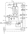
- FIG. 1 is a schematic diagram of a pressure swing adsorption-type oxygen concentrator in an example of illustrative embodiment in the present invention.
- FIG. 2 is a diagram to demonstrate a relation of a concentration of oxygen generated with a supply volume of raw material air required for a predetermined flow rate in a conventional oxygen concentrator.
- A-A′ represents a range of an airflow volume suppliable with a compressor and A′ represents a lower limit of an airflow volume suppliable with a compressor.
- FIG. 3 is a diagram to demonstrate a relation of a concentration of oxygen generated with a supply volume of raw material air required for a predetermined flow rate in an oxygen concentrator in the present invention.
- FIG. 4 is a schematic diagram of a pressure swing adsorption-type oxygen concentrator in another example of illustrative embodiment of the present invention.
- FIG. 5 is a schematic diagram to demonstrate the difference of a switching timing of a switch valve in the present invention with that in conventional art.
- FIG. 6 is a diagram to demonstrate a pressure waveform in an adsorption cylinder in an oxygen concentrator of the present invention.
- FIG. 1 is a schematic constitutional diagram of an apparatus illustrating one embodiment of a pressure swing adsorption-type oxygen concentrator of the present invention.
- 1 and 3 represent an oxygen concentrator and a user (patient) inhaling humidified oxygen-enriched air, respectively.
- Pressure swing adsorption-type oxygen concentrator 1 is equipped with external air intake filter 101 , compressor 103 , switching valve 104 , adsorption cylinder 105 , check valve 106 , product tank 107 , pressure regulating valve 108 , flow rate setting device 109 and filter 110 . With this, oxygen-enriched air can be generated by concentrating an oxygen gas from raw material air brought in from outside.
- Raw material air brought in an oxygen concentrator from atmosphere is first taken in from an air intake port equipped with external air intake filter 101 to eliminate foreign particles such as dust and the like into the apparatus as clean air not containing, from which coarse particulates, dusts and the like are eliminated.
- ordinary atmospheric air contains about 21% oxygen gas, about 77% nitrogen gas, 0.8% argon gas and 1.2% gases such as steam and the others.
- Such an oxygen concentrator selectively concentrates and isolates oxygen gas required for a breathing gas.
- a pressure swing adsorption method is used, in which raw material air is pressurized by compressor 103 to supply the air to adsorption cylinder 105 filled with adsorbents containing zeolites and the like, which selectively adsorb nitrogen gas molecules relative to oxygen gas molecules by successively switching targeted adsorption cylinders 105 by switching valve 104 , thereby about 77% nitrogen gas contained in raw material air inside adsorption cylinder 105 is selectively adsorbed and eliminated to take out unadsorbed oxygen gas from, one end of adsorption cylinder 105 into product tank 107 .
- Molecular sieve zeolites such as zeolite 5A, zeolite 13X, Li—X zeolite, MD-X zeolite and the like are used as an adsorbent selectively adsorbing nitrogen gas molecules relative to oxygen gas molecules.
- Adsorption cylinder 105 described above is composed of a cylindrical vessel filled with the adsorbents described above and is generally available as a one cylinder-type apparatus, which uses one adsorption cylinder to a desorption step to intermittently generate oxygen by successively switching an adsorption step, a two cylinder-type apparatus using two adsorption cylinders, which uses two adsorption cylinders to continuously generate oxygen, by switching an adsorption step and a desorption step in such a way that, while the one adsorption cylinder is under an adsorption step, the other adsorption cylinder is under a desorption step, or further a multiple cylinder-type apparatus having three cylinders or more.
- Multiple cylinder-type with two cylinders or more of adsorption cylinders 105 is preferably used in order to continuously and effectively produce oxygen-enriched air from raw material air.
- a rotating-type air compressor such as screw-type, rotary-type, scroll-type air compressors and the like may be used in some cases as compressor 103 described above in addition to a reciprocating-type air compressor.
- the power source of a motor to drive this compressor 103 may be alternate current or direct current.
- a nitrogen gas adsorbed on the adsorbents filled in adsorption cylinder 105 is now required to be desorbed from the adsorbents in order to reuse the adsorbents to adsorb the nitrogen gas again from freshly introduced raw material air.
- switching valve 104 is used to switch from a pressurized condition achieved by compressor 103 to a depressurized condition (for example, atmospheric pressure state or negative pressure state) to desorb the nitrogen gas adsorbed to regenerate the adsorbents.
- a depressurized condition for example, atmospheric pressure state or negative pressure state
- an oxygen-concentrated gas may be flown back as a purge gas from the product outlet side of the adsorption cylinder during the adsorption step or from product tank 107 in order to increase a desorption efficiency.
- An oxygen-concentrated gas is produced from raw material air and stored in product tank 107 .
- the oxygen-concentrated gas stored in product tank 107 contains, for example, an oxygen gas highly concentrated to a level of 95%.
- Pressure regulating valve 108 , flow rate setting device 109 and the like subsequently control the oxygen flow rate and pressure to supply to a user and feed to humidifier 201 , from which a humidified oxygen-concentrated gas is supplied to patient 3 .
- Such a humidifier used may include a non-water supply humidifier without using water, in which an oxygen-concentrated gas in dry state is humidified by the moisture brought from external air using a moisture permeation membrane module having moisture permeation membranes; a bubbling-type humidifier using water for humidification; or a surface evaporation type humidifier.
- a predetermined value on flow rate setting device 109 is detected to control the number of revolution in an electric motor for compressor 103 by control device 401 to control an airflow volume to be supplied to adsorption cylinder 105 .
- a predetermined flow rate is set at a low flow rate, lowering the number of revolution in an electric motor for the compressor suppresses the volume of raw material air to be supplied and the amount of oxygen to be generated, leading to reduction of electric power consumption.
- control to reduce the number of revolution of compressor 103 has a limit no matter how a predetermined flow rate of oxygen in an oxygen concentrator is set at a low flow rate, resulting in operation at a constant speed of a lower operation limit in compressor 103 when the flow rate is equal to a given value or less.
- a range in which compressor 103 can stably supply compressed air is an A-A′ range and the compressor is operated at a constant speed of lower limit A′ when a range of a predetermined flow rate is equal to 1 L/min or less.
- Adsorption cylinder 105 in an oxygen concentrator is designed to maintain an oxygen concentration at 90% or higher even at a maximum predetermined flow rate of the apparatus.
- a volume of raw material air is excessively supplied to a certain level at a lower limit of compressor operation in a low flow rate zone of a predetermined oxygen flow rate even if a volume of oxygen isolated is low, not only nitrogen molecules but also oxygen molecules are adsorbed on adsorbents in adsorption cylinder 105 , causing an excess adsorption phenomenon.
- the excess adsorption phenomenon can be prevented even at a predetermined flow rate of 1 L/min or less if a volume of airflow to be supplied by the compressor can be lowered, but the compressor cannot be stably driven at or below its rated conditions.
- the amount of oxygen generated in an oxygen-concentrated gas generated is reduced and the concentration of unadsorbed argon is increased, resulting in a phenomenon in which the oxygen concentration in the oxygen-concentrated gas is reduced in a low flow rate zone (at 1 L/min or less).
- an oxygen concentrator of the present invention is provided with a branch pipe equipped with leak valve 102 on a flow channel between compressor 103 and switching valve 104 to release excess raw material air.
- leak valve 102 is opened to release excess raw material air relative to a supply volume required for raw material air.
- FIG. 4 is a schematic constitutional diagram of an apparatus illustrating a pressure variable adsorption-type oxygen concentrator in another embodiment of the present invention.
- raw material air brought in from outside is entered in an air intake port equipped with external air intake filter 501 to eliminate foreign particles such as dust and the like.
- ordinary atmospheric air contains about 21% oxygen gas, about 77% nitrogen gas, 0.8% argon gas and 1.2% gases such as steam and the like.
- oxygen gas required for a breathing gas is concentrated and isolated.
- raw material air is pressurized and supplied by compressor 503 into two adsorption cylinders 505 A and 505 B filled with adsorbents containing zeolites and the like, which selectively adsorb nitrogen gas molecules relative to oxygen gas molecules, by successively switching targeted adsorption cylinders by switching valve 504 , and about 77% nitrogen gas contained in raw material air is selectively adsorbed and eliminated within the adsorption cylinders.
- Oxygen-enriched air containing an oxygen gas as a main component, which is not adsorbed in the adsorption cylinders described above is flown into product tank 507 via check valve 506 installed to prevent the gas from flowing back into the adsorption cylinders.
- a nitrogen gas adsorbed on the adsorbents filled in the adsorption cylinder is required to be desorbed from the adsorbents in order to reuse the adsorbents to adsorb a nitrogen gas again from freshly introduced raw material air.
- switching valve 504 switches from a pressurized condition achieved by compressor 503 to a depressurized condition (for example, atmospheric pressure state or negative pressure state) to desorb a nitrogen gas adsorbed to regenerate the adsorbents.
- a depressurized condition for example, atmospheric pressure state or negative pressure state
- an oxygen-concentrated gas may be flown back as a purge gas from the product end side of the adsorption cylinder (or a product tank) in an adsorption step in order to increase a desorption efficiency.
- An oxygen-concentrated gas is produced from raw material air to be stored in product tank 507 .
- the oxygen-concentrated gas stored in product tank 507 contains, for example, an oxygen gas highly concentrated to a level of 95% and is supplied to humidifier 512 by controlling the flow rate and pressure with a pressure regulating valve, flow rate setting device 509 (CV: control valve) or the like to supply a humidified oxygen-concentrated gas to patients.
- a predetermined value on flow rate setting device 509 is detected to control the number of revolution in an electric motor for compressor 503 by control device to control a volume of airflow to be supplied to adsorption cylinders.
- a predetermined flow rate is set at a low flow rate, lowering the number of revolution suppresses the amount of oxygen generated, leading to reduction of electric power consumption.
- a volume of raw material air is excessively supplied to a certain level at a lower limit of compressor operation, not only nitrogen molecules but also oxygen molecules are adsorbed on adsorbents in adsorption cylinders 505 A and 505 B to cause an excess adsorption phenomenon.
- switching valve 504 is switched during the adsorption step to control a volume of raw material air to be supplied to the adsorption cylinders and excess raw material air is released.
- a structure in a combination of four two-way valves (two-way electromagnetic valves, a 1 , a 2 , b 1 and b 2 ) as shown in FIG. 4 is adopted.
- Each electromagnetic valve may be connected by tubing or branch tubing, or the four electromagnetic valves may be assembled into a manifold.
- FIG. 5 demonstrates an open/shut timing of each two-way valve.
- adsorption cylinder 505 A When adsorption cylinder 505 A is supplied with compressed air from a compressor in an adsorption step, generally the other adsorption cylinder 505 B is in a desorption step and the adsorption cylinder under the pressurized condition is depressurized to release adsorbed nitrogen to atmosphere.
- two-way valve a 1 is opened but two-way valves a 2 and b 1 are closed, thereby compressed air is supplied to adsorption cylinder 505 A.
- two-way valve b 2 is opened to release a nitrogen-enriched gas in adsorption cylinder 505 B.
- an apparatus of the present invention opens two-way valve b 1 at a late stage of the adsorption step in adsorption cylinder 505 A to release part of compressed air supplied by compressor 503 from two-way valve b 1 through an exhaust line.
- This can reduce the amount of raw material air supplied from two-way valve a 1 to adsorption cylinder 505 A, preventing a phenomenon of excess oxygen adsorption.
- two-way valve b 2 at a late stage of the adsorption step in adsorption cylinder 505 B, part of compressed air is released from two-way valve b 2 through the exhaust line.
- Control of switch valve 504 is determined according to a predetermined value of an oxygen supply flow rate and a switching timing is controlled according to a predetermined signal of flow rate setting device 509 .
- a predetermined value is equal to 1 L/min or more
- the number of revolution of a motor for compressor 503 is controlled without changing the switching timing to control the supply volume of raw material air
- the timing to open two-way valves b 1 /b 2 constituting switching valve 504 at a late stage of the adsorption step is controlled ahead of time, thus controlling the volume of raw material air to be supplied to each adsorption cylinder 505 A and 505 B.
- a timing to open earlier may be controlled by proportionally adjusting a volume of raw material air to match a predetermined flow rate or controlled in a multistage way.
- a leak valve (electromagnetic valve, control valve (CV) and the like) is inserted between a compressor outlet and an inlet of an adsorption cylinder to release unnecessary raw material air, thus a concentration of oxygen generated is increased and a compressor can be stably driven without receiving any effects of surrounding conditions.
Landscapes
- Chemical & Material Sciences (AREA)
- Health & Medical Sciences (AREA)
- Engineering & Computer Science (AREA)
- Organic Chemistry (AREA)
- Analytical Chemistry (AREA)
- Emergency Medicine (AREA)
- Biomedical Technology (AREA)
- Life Sciences & Earth Sciences (AREA)
- Pulmonology (AREA)
- Anesthesiology (AREA)
- Oil, Petroleum & Natural Gas (AREA)
- Heart & Thoracic Surgery (AREA)
- Hematology (AREA)
- Chemical Kinetics & Catalysis (AREA)
- Animal Behavior & Ethology (AREA)
- General Health & Medical Sciences (AREA)
- Public Health (AREA)
- Veterinary Medicine (AREA)
- Inorganic Chemistry (AREA)
- General Chemical & Material Sciences (AREA)
- Separation Of Gases By Adsorption (AREA)
- Oxygen, Ozone, And Oxides In General (AREA)
Applications Claiming Priority (5)
| Application Number | Priority Date | Filing Date | Title |
|---|---|---|---|
| JP2006-256850 | 2006-09-22 | ||
| JP2006256850 | 2006-09-22 | ||
| JP2007-036036 | 2007-02-16 | ||
| JP2007036036 | 2007-02-16 | ||
| PCT/JP2007/069119 WO2008035817A1 (en) | 2006-09-22 | 2007-09-21 | Oxygen concentrator |
Publications (2)
| Publication Number | Publication Date |
|---|---|
| US20090255403A1 US20090255403A1 (en) | 2009-10-15 |
| US8070864B2 true US8070864B2 (en) | 2011-12-06 |
Family
ID=39200633
Family Applications (1)
| Application Number | Title | Priority Date | Filing Date |
|---|---|---|---|
| US12/310,890 Active 2028-06-21 US8070864B2 (en) | 2006-09-22 | 2007-09-21 | Oxygen concentrator |
Country Status (13)
| Country | Link |
|---|---|
| US (1) | US8070864B2 (zh) |
| EP (1) | EP2065067B1 (zh) |
| JP (1) | JP5080483B2 (zh) |
| KR (1) | KR101325472B1 (zh) |
| CN (1) | CN101522246B (zh) |
| AU (1) | AU2007298122B2 (zh) |
| CA (1) | CA2663760C (zh) |
| ES (1) | ES2452724T3 (zh) |
| HK (2) | HK1131077A1 (zh) |
| MY (1) | MY149344A (zh) |
| SG (1) | SG174820A1 (zh) |
| TW (1) | TWI410260B (zh) |
| WO (1) | WO2008035817A1 (zh) |
Cited By (7)
| Publication number | Priority date | Publication date | Assignee | Title |
|---|---|---|---|---|
| US20130205665A1 (en) * | 2010-01-26 | 2013-08-15 | Osaka Gas Co., Ltd. | Enrichment System for Combustible Gas |
| WO2018006157A1 (en) * | 2016-07-08 | 2018-01-11 | Cpap Direct Ltd. | Apparatus and methods for cleaning and oxygen-enriching air |
| US9956371B2 (en) | 2015-03-24 | 2018-05-01 | Ventec Life Systems, Inc. | Ventilator with integrated cough-assist |
| US10773049B2 (en) | 2016-06-21 | 2020-09-15 | Ventec Life Systems, Inc. | Cough-assist systems with humidifier bypass |
| US20210086003A1 (en) * | 2019-09-24 | 2021-03-25 | Cobham Mission Systems Davenport Lss Inc. | Composition control for obogs |
| US11191915B2 (en) | 2018-05-13 | 2021-12-07 | Ventec Life Systems, Inc. | Portable medical ventilator system using portable oxygen concentrators |
| US11247015B2 (en) | 2015-03-24 | 2022-02-15 | Ventec Life Systems, Inc. | Ventilator with integrated oxygen production |
Families Citing this family (12)
| Publication number | Priority date | Publication date | Assignee | Title |
|---|---|---|---|---|
| US7384297B2 (en) * | 2006-11-07 | 2008-06-10 | King Jr Lloyd Herbert | Wire connector |
| US20150265859A1 (en) * | 2013-11-25 | 2015-09-24 | Stan A. Sanders | Oxygen belt breathing pack |
| JP6313120B2 (ja) * | 2014-05-20 | 2018-04-18 | 帝人ファーマ株式会社 | 酸素濃縮装置のメンテナンス管理システム |
| JPWO2016098180A1 (ja) * | 2014-12-16 | 2017-06-15 | 小林 照男 | 酸素濃縮装置 |
| US9610532B2 (en) * | 2014-12-30 | 2017-04-04 | Pacific Consolidated Industries, Inc. | Method and system for high reliability oxygen supply from multiple units |
| WO2016117831A1 (ko) * | 2015-01-22 | 2016-07-28 | 주식회사 산청 | 인공호흡장치 |
| CN108136313B (zh) * | 2015-09-29 | 2021-05-04 | 林德股份公司 | 阀组件和吸附器站 |
| US10953187B2 (en) * | 2017-06-06 | 2021-03-23 | Separation Design Group Llc | Configurable oxygen concentrator and related method |
| AU2019253967A1 (en) * | 2018-04-20 | 2020-12-10 | Roam Technologies Pty Ltd | Systems and methods for providing concentrated oxygen to a user |
| JP6927927B2 (ja) * | 2018-06-12 | 2021-09-01 | ダイキン工業株式会社 | 酸素供給装置 |
| CN112996584A (zh) * | 2018-11-15 | 2021-06-18 | 帝人制药株式会社 | 氧浓缩装置、控制方法及控制程序 |
| US20230012016A1 (en) * | 2019-11-27 | 2023-01-12 | ResMed Asia Pte. Ltd. | Oxygen tank with improved oxygen storage |
Citations (21)
| Publication number | Priority date | Publication date | Assignee | Title |
|---|---|---|---|---|
| US3880616A (en) * | 1973-11-19 | 1975-04-29 | Bendix Corp | Respiratory support system |
| JPS5771804A (en) | 1980-10-24 | 1982-05-04 | Hitachi Ltd | Controlling apparatus of oxygen concentration |
| US4584001A (en) * | 1983-08-09 | 1986-04-22 | Vbm Corporation | Modular oxygen generator |
| US5071453A (en) | 1989-09-28 | 1991-12-10 | Litton Systems, Inc. | Oxygen concentrator with pressure booster and oxygen concentration monitoring |
| US5137549A (en) | 1988-10-14 | 1992-08-11 | Vbm Corporation | Two stage super-enriched oxygen concentrator |
| JPH08133703A (ja) | 1994-11-04 | 1996-05-28 | Nippon Rufuto Kk | 呼吸用酸素供給装置 |
| JPH09183601A (ja) | 1995-12-28 | 1997-07-15 | Teijin Ltd | 酸素富化空気供給装置 |
| WO1998028061A1 (en) | 1994-09-28 | 1998-07-02 | Sequal Technologies, Inc. | Improved fluid fractionator |
| JP2857045B2 (ja) | 1993-01-04 | 1999-02-10 | 帝人株式会社 | 酸素濃縮装置 |
| JPH11303792A (ja) | 1998-04-24 | 1999-11-02 | Hitachi Ltd | 圧縮機の容量調節方法およびその装置 |
| JPH11309328A (ja) | 1998-04-30 | 1999-11-09 | Daikin Ind Ltd | 酸素濃縮機 |
| JP3063907B2 (ja) | 1990-02-20 | 2000-07-12 | 旭硝子株式会社 | エチレン―四弗化エチレン系共重合体の製造方法 |
| JP2000516854A (ja) | 1996-12-20 | 2000-12-19 | シークォル テクノロジーズ,インコーポレイテッド | 改良された流体分別器 |
| US6558451B2 (en) * | 2000-05-10 | 2003-05-06 | Airsep Corporation | Multiple bed pressure swing adsorption method and apparatus |
| JP2003180836A (ja) | 2001-12-18 | 2003-07-02 | Teijin Ltd | 医療用圧力変動吸着型酸素濃縮装置 |
| JP2004085048A (ja) | 2002-08-26 | 2004-03-18 | Sumitomo Heavy Ind Ltd | 極低温冷凍装置、及び、その運転方法 |
| US6712877B2 (en) * | 2002-08-27 | 2004-03-30 | Litton Systems, Inc. | Oxygen concentrator system |
| JP2004129761A (ja) | 2002-10-09 | 2004-04-30 | Sanyo Electric Industries Co Ltd | 医療用酸素濃縮装置 |
| JP2005087937A (ja) | 2003-09-19 | 2005-04-07 | Sanyo Electric Industries Co Ltd | Psaガス分離装置 |
| JP2005211392A (ja) | 2004-01-30 | 2005-08-11 | Teijin Pharma Ltd | 医療用酸素濃縮器 |
| JP2006062932A (ja) | 2004-08-30 | 2006-03-09 | Ngk Spark Plug Co Ltd | 酸素濃縮装置 |
Family Cites Families (5)
| Publication number | Priority date | Publication date | Assignee | Title |
|---|---|---|---|---|
| US5746806A (en) | 1996-08-15 | 1998-05-05 | Nellcor Puritan Bennett Incorporated | Apparatus and method for controlling output of an oxygen concentrator |
| JP4203716B2 (ja) * | 2002-09-02 | 2009-01-07 | 株式会社日立製作所 | 気体分離装置 |
| WO2005009590A2 (en) | 2003-07-24 | 2005-02-03 | Thomas Industries Inc. | Oxygen concentrator construction, supply and repair |
| JP4404583B2 (ja) * | 2003-08-12 | 2010-01-27 | 山陽電子工業株式会社 | 酸素濃縮装置 |
| US7402193B2 (en) * | 2005-04-05 | 2008-07-22 | Respironics Oxytec, Inc. | Portable oxygen concentrator |
-
2007
- 2007-09-21 SG SG2011067089A patent/SG174820A1/en unknown
- 2007-09-21 MY MYPI20091147A patent/MY149344A/en unknown
- 2007-09-21 US US12/310,890 patent/US8070864B2/en active Active
- 2007-09-21 KR KR1020097007967A patent/KR101325472B1/ko active IP Right Grant
- 2007-09-21 TW TW096135404A patent/TWI410260B/zh not_active IP Right Cessation
- 2007-09-21 WO PCT/JP2007/069119 patent/WO2008035817A1/ja active Application Filing
- 2007-09-21 ES ES07828860.2T patent/ES2452724T3/es active Active
- 2007-09-21 CA CA2663760A patent/CA2663760C/en not_active Expired - Fee Related
- 2007-09-21 AU AU2007298122A patent/AU2007298122B2/en not_active Expired - Fee Related
- 2007-09-21 EP EP07828860.2A patent/EP2065067B1/en active Active
- 2007-09-21 CN CN2007800349862A patent/CN101522246B/zh active Active
- 2007-09-21 JP JP2008535423A patent/JP5080483B2/ja active Active
-
2009
- 2009-10-06 HK HK09109235.7A patent/HK1131077A1/xx not_active IP Right Cessation
- 2009-11-05 HK HK09110322.9A patent/HK1132687A1/xx not_active IP Right Cessation
Patent Citations (21)
| Publication number | Priority date | Publication date | Assignee | Title |
|---|---|---|---|---|
| US3880616A (en) * | 1973-11-19 | 1975-04-29 | Bendix Corp | Respiratory support system |
| JPS5771804A (en) | 1980-10-24 | 1982-05-04 | Hitachi Ltd | Controlling apparatus of oxygen concentration |
| US4584001A (en) * | 1983-08-09 | 1986-04-22 | Vbm Corporation | Modular oxygen generator |
| US5137549A (en) | 1988-10-14 | 1992-08-11 | Vbm Corporation | Two stage super-enriched oxygen concentrator |
| US5071453A (en) | 1989-09-28 | 1991-12-10 | Litton Systems, Inc. | Oxygen concentrator with pressure booster and oxygen concentration monitoring |
| JP3063907B2 (ja) | 1990-02-20 | 2000-07-12 | 旭硝子株式会社 | エチレン―四弗化エチレン系共重合体の製造方法 |
| JP2857045B2 (ja) | 1993-01-04 | 1999-02-10 | 帝人株式会社 | 酸素濃縮装置 |
| WO1998028061A1 (en) | 1994-09-28 | 1998-07-02 | Sequal Technologies, Inc. | Improved fluid fractionator |
| JPH08133703A (ja) | 1994-11-04 | 1996-05-28 | Nippon Rufuto Kk | 呼吸用酸素供給装置 |
| JPH09183601A (ja) | 1995-12-28 | 1997-07-15 | Teijin Ltd | 酸素富化空気供給装置 |
| JP2000516854A (ja) | 1996-12-20 | 2000-12-19 | シークォル テクノロジーズ,インコーポレイテッド | 改良された流体分別器 |
| JPH11303792A (ja) | 1998-04-24 | 1999-11-02 | Hitachi Ltd | 圧縮機の容量調節方法およびその装置 |
| JPH11309328A (ja) | 1998-04-30 | 1999-11-09 | Daikin Ind Ltd | 酸素濃縮機 |
| US6558451B2 (en) * | 2000-05-10 | 2003-05-06 | Airsep Corporation | Multiple bed pressure swing adsorption method and apparatus |
| JP2003180836A (ja) | 2001-12-18 | 2003-07-02 | Teijin Ltd | 医療用圧力変動吸着型酸素濃縮装置 |
| JP2004085048A (ja) | 2002-08-26 | 2004-03-18 | Sumitomo Heavy Ind Ltd | 極低温冷凍装置、及び、その運転方法 |
| US6712877B2 (en) * | 2002-08-27 | 2004-03-30 | Litton Systems, Inc. | Oxygen concentrator system |
| JP2004129761A (ja) | 2002-10-09 | 2004-04-30 | Sanyo Electric Industries Co Ltd | 医療用酸素濃縮装置 |
| JP2005087937A (ja) | 2003-09-19 | 2005-04-07 | Sanyo Electric Industries Co Ltd | Psaガス分離装置 |
| JP2005211392A (ja) | 2004-01-30 | 2005-08-11 | Teijin Pharma Ltd | 医療用酸素濃縮器 |
| JP2006062932A (ja) | 2004-08-30 | 2006-03-09 | Ngk Spark Plug Co Ltd | 酸素濃縮装置 |
Non-Patent Citations (3)
| Title |
|---|
| European Search Report of European Patent Application No. 07828860.2 dated Mar. 2, 2010 (EPO). |
| International Search Report mailed Oct. 30, 2007. |
| Office Action of Japanese Patent Application No. 2008-535423 mailed on Aug. 2, 2011 (Japan). |
Cited By (20)
| Publication number | Priority date | Publication date | Assignee | Title |
|---|---|---|---|---|
| US20130205665A1 (en) * | 2010-01-26 | 2013-08-15 | Osaka Gas Co., Ltd. | Enrichment System for Combustible Gas |
| US8932387B2 (en) * | 2010-01-26 | 2015-01-13 | Osaka Gas Co., Ltd. | Enrichment system for combustible gas |
| US10758699B2 (en) | 2015-03-24 | 2020-09-01 | Ventec Life Systems, Inc. | Secretion trap |
| US11247015B2 (en) | 2015-03-24 | 2022-02-15 | Ventec Life Systems, Inc. | Ventilator with integrated oxygen production |
| US10046134B2 (en) | 2015-03-24 | 2018-08-14 | Ventec Life Systems, Inc. | Pressure swing adsorption oxygen generator |
| US10105509B2 (en) | 2015-03-24 | 2018-10-23 | Ventec Life Systems, Inc. | Active exhalation valve |
| US10245406B2 (en) | 2015-03-24 | 2019-04-02 | Ventec Life Systems, Inc. | Ventilator with integrated oxygen production |
| US10315002B2 (en) | 2015-03-24 | 2019-06-11 | Ventec Life Systems, Inc. | Ventilator with integrated oxygen production |
| US10518059B2 (en) | 2015-03-24 | 2019-12-31 | Ventec Life Systems, Inc. | Passive leak valve |
| US10576237B2 (en) | 2015-03-24 | 2020-03-03 | Ventec Life Systems, Inc. | Active exhalation valve |
| US11344692B2 (en) | 2015-03-24 | 2022-05-31 | Ventec Life Systems, Inc. | Respiratory therapy systems and methods |
| US11291791B2 (en) | 2015-03-24 | 2022-04-05 | Ventee Life Systems, Inc. | Ventilator with integrated cough-assist |
| US9956371B2 (en) | 2015-03-24 | 2018-05-01 | Ventec Life Systems, Inc. | Ventilator with integrated cough-assist |
| US11185655B2 (en) | 2015-03-24 | 2021-11-30 | Ventec Life Systems, Inc. | Passive leak valve |
| US10773049B2 (en) | 2016-06-21 | 2020-09-15 | Ventec Life Systems, Inc. | Cough-assist systems with humidifier bypass |
| US11679229B2 (en) | 2016-06-21 | 2023-06-20 | Ventec Life Systems, Inc. | Cough-assist systems with humidifier bypass |
| WO2018006157A1 (en) * | 2016-07-08 | 2018-01-11 | Cpap Direct Ltd. | Apparatus and methods for cleaning and oxygen-enriching air |
| US11191915B2 (en) | 2018-05-13 | 2021-12-07 | Ventec Life Systems, Inc. | Portable medical ventilator system using portable oxygen concentrators |
| US20210086003A1 (en) * | 2019-09-24 | 2021-03-25 | Cobham Mission Systems Davenport Lss Inc. | Composition control for obogs |
| US11577101B2 (en) * | 2019-09-24 | 2023-02-14 | Mission Systems Davenport Inc. | Composition control for OBOGS |
Also Published As
| Publication number | Publication date |
|---|---|
| KR20090068341A (ko) | 2009-06-26 |
| WO2008035817A1 (en) | 2008-03-27 |
| AU2007298122A1 (en) | 2008-03-27 |
| HK1131077A1 (en) | 2010-01-15 |
| EP2065067A1 (en) | 2009-06-03 |
| CN101522246B (zh) | 2012-09-26 |
| EP2065067B1 (en) | 2013-12-25 |
| EP2065067A4 (en) | 2010-03-31 |
| MY149344A (en) | 2013-08-30 |
| SG174820A1 (en) | 2011-10-28 |
| CN101522246A (zh) | 2009-09-02 |
| CA2663760A1 (en) | 2008-03-27 |
| ES2452724T3 (es) | 2014-04-02 |
| US20090255403A1 (en) | 2009-10-15 |
| JP5080483B2 (ja) | 2012-11-21 |
| TW200824735A (en) | 2008-06-16 |
| AU2007298122B2 (en) | 2013-02-07 |
| HK1132687A1 (en) | 2010-03-05 |
| TWI410260B (zh) | 2013-10-01 |
| CA2663760C (en) | 2014-06-10 |
| KR101325472B1 (ko) | 2013-11-07 |
| JPWO2008035817A1 (ja) | 2010-01-28 |
Similar Documents
| Publication | Publication Date | Title |
|---|---|---|
| US8070864B2 (en) | Oxygen concentrator | |
| EP2145646B1 (en) | Oxygen enricher | |
| JP5357264B2 (ja) | 酸素濃縮装置 | |
| US20050081713A1 (en) | Gas concentration method and its apparatus | |
| WO2014046297A1 (ja) | 酸素濃縮装置 | |
| JP4922739B2 (ja) | 酸素濃縮装置 | |
| JP2009061110A (ja) | 酸素濃縮装置 | |
| JP5242996B2 (ja) | 酸素濃縮装置 | |
| JP5112839B2 (ja) | 酸素濃縮装置 | |
| JP5524574B2 (ja) | 酸素濃縮装置 | |
| JP2008178795A (ja) | 酸素濃縮装置 | |
| JP5065714B2 (ja) | 酸素濃縮装置 | |
| JP2009273623A (ja) | 酸素濃縮装置 | |
| JP2009254502A (ja) | 酸素濃縮装置 |
Legal Events
| Date | Code | Title | Description |
|---|---|---|---|
| AS | Assignment |
Owner name: TEIJIN PHARMA LIMITED, JAPAN Free format text: ASSIGNMENT OF ASSIGNORS INTEREST;ASSIGNORS:UCHIYAMA, MITSURU;FUJIMOTO, KATSUSHI;ANDO, MAKOTO;REEL/FRAME:022421/0829 Effective date: 20090217 |
|
| STCF | Information on status: patent grant |
Free format text: PATENTED CASE |
|
| AS | Assignment |
Owner name: TEIJIN LIMITED, JAPAN Free format text: COPORATE SPLIT;ASSIGNOR:TEIJIN PHARMA LIMITED;REEL/FRAME:029660/0475 Effective date: 20121024 |
|
| FPAY | Fee payment |
Year of fee payment: 4 |
|
| FEPP | Fee payment procedure |
Free format text: PAYOR NUMBER ASSIGNED (ORIGINAL EVENT CODE: ASPN); ENTITY STATUS OF PATENT OWNER: LARGE ENTITY |
|
| MAFP | Maintenance fee payment |
Free format text: PAYMENT OF MAINTENANCE FEE, 8TH YEAR, LARGE ENTITY (ORIGINAL EVENT CODE: M1552); ENTITY STATUS OF PATENT OWNER: LARGE ENTITY Year of fee payment: 8 |
|
| MAFP | Maintenance fee payment |
Free format text: PAYMENT OF MAINTENANCE FEE, 12TH YEAR, LARGE ENTITY (ORIGINAL EVENT CODE: M1553); ENTITY STATUS OF PATENT OWNER: LARGE ENTITY Year of fee payment: 12 |