US8070708B2 - Device and method for controlling in-vivo pressure - Google Patents
Device and method for controlling in-vivo pressure Download PDFInfo
- Publication number
- US8070708B2 US8070708B2 US10/597,666 US59766605D US8070708B2 US 8070708 B2 US8070708 B2 US 8070708B2 US 59766605 D US59766605 D US 59766605D US 8070708 B2 US8070708 B2 US 8070708B2
- Authority
- US
- United States
- Prior art keywords
- pressure
- shunt
- dprd
- left atrium
- pressure differential
- Prior art date
- Legal status (The legal status is an assumption and is not a legal conclusion. Google has not performed a legal analysis and makes no representation as to the accuracy of the status listed.)
- Expired - Lifetime
Links
Images


Classifications
-
- A—HUMAN NECESSITIES
- A61—MEDICAL OR VETERINARY SCIENCE; HYGIENE
- A61B—DIAGNOSIS; SURGERY; IDENTIFICATION
- A61B17/00—Surgical instruments, devices or methods
- A61B17/11—Surgical instruments, devices or methods for performing anastomosis; Buttons for anastomosis
-
- A—HUMAN NECESSITIES
- A61—MEDICAL OR VETERINARY SCIENCE; HYGIENE
- A61F—FILTERS IMPLANTABLE INTO BLOOD VESSELS; PROSTHESES; DEVICES PROVIDING PATENCY TO, OR PREVENTING COLLAPSING OF, TUBULAR STRUCTURES OF THE BODY, e.g. STENTS; ORTHOPAEDIC, NURSING OR CONTRACEPTIVE DEVICES; FOMENTATION; TREATMENT OR PROTECTION OF EYES OR EARS; BANDAGES, DRESSINGS OR ABSORBENT PADS; FIRST-AID KITS
- A61F2/00—Filters implantable into blood vessels; Prostheses, i.e. artificial substitutes or replacements for parts of the body; Appliances for connecting them with the body; Devices providing patency to, or preventing collapsing of, tubular structures of the body, e.g. stents
- A61F2/02—Prostheses implantable into the body
- A61F2/24—Heart valves ; Vascular valves, e.g. venous valves; Heart implants, e.g. passive devices for improving the function of the native valve or the heart muscle; Transmyocardial revascularisation [TMR] devices; Valves implantable in the body
- A61F2/2442—Annuloplasty rings or inserts for correcting the valve shape; Implants for improving the function of a native heart valve
-
- A—HUMAN NECESSITIES
- A61—MEDICAL OR VETERINARY SCIENCE; HYGIENE
- A61M—DEVICES FOR INTRODUCING MEDIA INTO, OR ONTO, THE BODY; DEVICES FOR TRANSDUCING BODY MEDIA OR FOR TAKING MEDIA FROM THE BODY; DEVICES FOR PRODUCING OR ENDING SLEEP OR STUPOR
- A61M60/00—Blood pumps; Devices for mechanical circulatory actuation; Balloon pumps for circulatory assistance
- A61M60/10—Location thereof with respect to the patient's body
- A61M60/122—Implantable pumps or pumping devices, i.e. the blood being pumped inside the patient's body
- A61M60/126—Implantable pumps or pumping devices, i.e. the blood being pumped inside the patient's body implantable via, into, inside, in line, branching on, or around a blood vessel
- A61M60/148—Implantable pumps or pumping devices, i.e. the blood being pumped inside the patient's body implantable via, into, inside, in line, branching on, or around a blood vessel in line with a blood vessel using resection or like techniques, e.g. permanent endovascular heart assist devices
-
- A—HUMAN NECESSITIES
- A61—MEDICAL OR VETERINARY SCIENCE; HYGIENE
- A61B—DIAGNOSIS; SURGERY; IDENTIFICATION
- A61B17/00—Surgical instruments, devices or methods
- A61B17/00234—Surgical instruments, devices or methods for minimally invasive surgery
-
- A—HUMAN NECESSITIES
- A61—MEDICAL OR VETERINARY SCIENCE; HYGIENE
- A61B—DIAGNOSIS; SURGERY; IDENTIFICATION
- A61B5/00—Measuring for diagnostic purposes; Identification of persons
- A61B5/02—Detecting, measuring or recording for evaluating the cardiovascular system, e.g. pulse, heart rate, blood pressure or blood flow
- A61B5/021—Measuring pressure in heart or blood vessels
- A61B5/0215—Measuring pressure in heart or blood vessels by means inserted into the body
-
- A—HUMAN NECESSITIES
- A61—MEDICAL OR VETERINARY SCIENCE; HYGIENE
- A61F—FILTERS IMPLANTABLE INTO BLOOD VESSELS; PROSTHESES; DEVICES PROVIDING PATENCY TO, OR PREVENTING COLLAPSING OF, TUBULAR STRUCTURES OF THE BODY, e.g. STENTS; ORTHOPAEDIC, NURSING OR CONTRACEPTIVE DEVICES; FOMENTATION; TREATMENT OR PROTECTION OF EYES OR EARS; BANDAGES, DRESSINGS OR ABSORBENT PADS; FIRST-AID KITS
- A61F2/00—Filters implantable into blood vessels; Prostheses, i.e. artificial substitutes or replacements for parts of the body; Appliances for connecting them with the body; Devices providing patency to, or preventing collapsing of, tubular structures of the body, e.g. stents
- A61F2/02—Prostheses implantable into the body
- A61F2/24—Heart valves ; Vascular valves, e.g. venous valves; Heart implants, e.g. passive devices for improving the function of the native valve or the heart muscle; Transmyocardial revascularisation [TMR] devices; Valves implantable in the body
- A61F2/2476—Valves implantable in the body not otherwise provided for
-
- A—HUMAN NECESSITIES
- A61—MEDICAL OR VETERINARY SCIENCE; HYGIENE
- A61M—DEVICES FOR INTRODUCING MEDIA INTO, OR ONTO, THE BODY; DEVICES FOR TRANSDUCING BODY MEDIA OR FOR TAKING MEDIA FROM THE BODY; DEVICES FOR PRODUCING OR ENDING SLEEP OR STUPOR
- A61M27/00—Drainage appliance for wounds or the like, i.e. wound drains, implanted drains
- A61M27/002—Implant devices for drainage of body fluids from one part of the body to another
-
- A—HUMAN NECESSITIES
- A61—MEDICAL OR VETERINARY SCIENCE; HYGIENE
- A61B—DIAGNOSIS; SURGERY; IDENTIFICATION
- A61B17/00—Surgical instruments, devices or methods
- A61B17/00234—Surgical instruments, devices or methods for minimally invasive surgery
- A61B2017/00238—Type of minimally invasive operation
- A61B2017/00243—Type of minimally invasive operation cardiac
- A61B2017/00247—Making holes in the wall of the heart, e.g. laser Myocardial revascularization
- A61B2017/00252—Making holes in the wall of the heart, e.g. laser Myocardial revascularization for by-pass connections, i.e. connections from heart chamber to blood vessel or from blood vessel to blood vessel
-
- A—HUMAN NECESSITIES
- A61—MEDICAL OR VETERINARY SCIENCE; HYGIENE
- A61B—DIAGNOSIS; SURGERY; IDENTIFICATION
- A61B17/00—Surgical instruments, devices or methods
- A61B17/0057—Implements for plugging an opening in the wall of a hollow or tubular organ, e.g. for sealing a vessel puncture or closing a cardiac septal defect
- A61B2017/00575—Implements for plugging an opening in the wall of a hollow or tubular organ, e.g. for sealing a vessel puncture or closing a cardiac septal defect for closure at remote site, e.g. closing atrial septum defects
- A61B2017/00592—Elastic or resilient implements
-
- A—HUMAN NECESSITIES
- A61—MEDICAL OR VETERINARY SCIENCE; HYGIENE
- A61B—DIAGNOSIS; SURGERY; IDENTIFICATION
- A61B17/00—Surgical instruments, devices or methods
- A61B17/0057—Implements for plugging an opening in the wall of a hollow or tubular organ, e.g. for sealing a vessel puncture or closing a cardiac septal defect
- A61B2017/00575—Implements for plugging an opening in the wall of a hollow or tubular organ, e.g. for sealing a vessel puncture or closing a cardiac septal defect for closure at remote site, e.g. closing atrial septum defects
- A61B2017/00606—Implements H-shaped in cross-section, i.e. with occluders on both sides of the opening
-
- A—HUMAN NECESSITIES
- A61—MEDICAL OR VETERINARY SCIENCE; HYGIENE
- A61B—DIAGNOSIS; SURGERY; IDENTIFICATION
- A61B17/00—Surgical instruments, devices or methods
- A61B17/11—Surgical instruments, devices or methods for performing anastomosis; Buttons for anastomosis
- A61B2017/1107—Surgical instruments, devices or methods for performing anastomosis; Buttons for anastomosis for blood vessels
-
- A—HUMAN NECESSITIES
- A61—MEDICAL OR VETERINARY SCIENCE; HYGIENE
- A61B—DIAGNOSIS; SURGERY; IDENTIFICATION
- A61B17/00—Surgical instruments, devices or methods
- A61B17/11—Surgical instruments, devices or methods for performing anastomosis; Buttons for anastomosis
- A61B2017/1139—Side-to-side connections, e.g. shunt or X-connections
-
- A—HUMAN NECESSITIES
- A61—MEDICAL OR VETERINARY SCIENCE; HYGIENE
- A61F—FILTERS IMPLANTABLE INTO BLOOD VESSELS; PROSTHESES; DEVICES PROVIDING PATENCY TO, OR PREVENTING COLLAPSING OF, TUBULAR STRUCTURES OF THE BODY, e.g. STENTS; ORTHOPAEDIC, NURSING OR CONTRACEPTIVE DEVICES; FOMENTATION; TREATMENT OR PROTECTION OF EYES OR EARS; BANDAGES, DRESSINGS OR ABSORBENT PADS; FIRST-AID KITS
- A61F2/00—Filters implantable into blood vessels; Prostheses, i.e. artificial substitutes or replacements for parts of the body; Appliances for connecting them with the body; Devices providing patency to, or preventing collapsing of, tubular structures of the body, e.g. stents
- A61F2/02—Prostheses implantable into the body
- A61F2/24—Heart valves ; Vascular valves, e.g. venous valves; Heart implants, e.g. passive devices for improving the function of the native valve or the heart muscle; Transmyocardial revascularisation [TMR] devices; Valves implantable in the body
- A61F2/2493—Transmyocardial revascularisation [TMR] devices
Definitions
- the present invention relates to devices and methods for reducing or regulating pressure within a circulatory system, and in particular to regulate blood pressure in a heart.
- CHF is recognized as one of the most common causes of hospitalization and mortality in Western society, and has a great impact on the quality of life.
- CHF is a disorder characterized by low systemic perfusion and inefficient cardiac function. CHF causes may include myocardial insult due to ischemia, cardiomyopathy and other processes.
- Pathophysiologic mechanisms that are directly associated with CHF include reduced cardiac output, increase in cardiac filling pressures, and fluid accumulation, which may lead to, for example, pulmonar congestion and dyspnea.
- Impairment of systolic function may result in poor left ventricular contraction and reduced cardiac output, which may generate clinical symptoms including effort intolerance, dyspnea, reduced longevity, edema (lung or peripheral) and pain.
- a patient with systolic dysfunction may usually have a larger left ventricle because of phenomena called cardiac remodeling aimed to maintain adequate stroke-volume.
- cardiac remodeling aimed to maintain adequate stroke-volume.
- This pathophisiologic mechanism is associated with increased atrial pressure and left ventricular filling pressure.
- the left ventricle With abnormal diastolic function, the left ventricle may be stiff and markedly less compliant partly because of abnormal relaxation leading to inadequate cardiac filling at normal pressures. Maintenance of adequate cardiac filling at higher filling pressures may be needed to maintain cardiac output. This mandatory rise of filling pressure to maintain cardiac filling and output may lead to pulmonary venous hypertension and lung edema.
- pharmacological e.g., diuretics
- assist systems e.g., pumps
- surgical treatments e.g., vasodilators
- vasodilators have been used to reduce the workload of the heart by reducing systemic vascular resistance and diuretics to prevent fluid accumulation and edema formation, and reduce cardiac filling pressure.
- Assist devices used to treat CHF may include, for example, mechanical pumps.
- Mechanical pumps reduce the load on the heart by performing all or part of the pumping function normally done by the heart.
- mechanical pumps are used, for example, to sustain the patient while a donor heart for transplantation becomes available for the patient.
- pacing devices used to treat CHF.
- Resysnchronization pacemakers have also been used to treat CHF.
- LVAD left ventricular assist device
- all the assist devices currently used are intended to improve pumping capacity of the heart and increase cardiac output to levels compatible with normal life, reducing filling pressures and/or preventing edema formation.
- cardiac transplantation may be used to treat extreme cardiac dysfunction cases, however this procedure is highly invasive and is limited by the availability of donor hearts.
- the mechanical devices may allow propulsion of significant amount of blood (liters/min) and this is also their main limitation. The need for power supply, relatively large pumps and possibility of hemolysis and infection are all of concern.
- FIG. 1A is a schematic illustration of a Differential Pressure Regulation Device (DPRD), in accordance with an exemplary embodiment of the invention
- FIGS. 1B-1I are schematic illustrations of additional embodiments of Differential Pressure Regulation Devices (DPRD), in accordance with some embodiments of the invention.
- DPRD Differential Pressure Regulation Devices
- FIG. 1J is a chart describing an example of a pressure curve related to the relationship between the change in pressure difference between two lumens, the flow through the flow control mechanism and the orifice area, in accordance with an exemplary embodiment of the present invention
- FIGS. 2A and 2B are schematic illustrations of a cross-section view and a side view, respectively, of an adjustable shunt, tube or other structure in accordance with an exemplary embodiment of the invention
- FIG. 3 is a schematic illustration of a shunt in accordance with another exemplary embodiment of the invention.
- FIG. 4 is a schematic illustration of a shunt including a Flow Regulation Mechanism (FRM) in accordance with an exemplary embodiment of the invention
- FIG. 5 is a schematic illustration of the shunt of FIG. 4 and incorporating a FRM in an open state in accordance with an exemplary embodiment of the invention
- FIG. 6 is a schematic illustration of a FRM in accordance with another exemplary embodiment of the invention, which may be used, for example, in conjunction with the DPRD of FIG. 1 , the shunt of FIGS. 2A-2B , or the shunt of FIG. 3 ;
- FIG. 7 is a schematic illustration of a FRM in accordance with another exemplary embodiment of the invention, which may be used, for example, in conjunction with the DPRD of FIG. 1 , the shunt of FIGS. 2A-2B , or the shunt of FIG. 3 ;
- FIG. 8 is a schematic illustration of a FRM in accordance with another exemplary embodiment of the invention, which may be used, for example, in conjunction with the DPRD of FIG. 1 , the shunt of FIGS. 2A-2B , or the shunt of FIG. 3 ;
- FIG. 9 is a schematic illustration of a FRM within a heart, in accordance with another exemplary embodiment of the invention.
- FIG. 10 is a schematic illustration of a FRM in accordance with another exemplary embodiment of the invention, which may be used, for example, in conjunction with the DPRD of FIG. 1 , the shunt of FIGS. 2A-2B , or the shunt of FIG. 3 ;
- FIG. 11 is a schematic illustration of a FRM in accordance with another exemplary embodiment of the invention, which may be used, for example, in conjunction with the DPRD of FIG. 1 , the shunt of FIGS. 2A-2B , or the shunt of FIG. 3 ;
- FIG. 12 is a schematic illustration of a FRM in accordance with another exemplary embodiment of the invention, which may be used, for example, in conjunction with the DPRD of FIG. 1 , the shunt of FIGS. 2A-2B , or the shunt of FIG. 3 ;
- FIG. 13A is a schematic illustration of an apparatus for remotely controlling a DPRD in accordance with some embodiments of the present invention.
- FIGS. 13B-E are schematic illustrations of mechanisms for remotely controlling a DPRD, in accordance with some embodiments of the present invention.
- FIG. 14 is a flow chart illustrating a method of controlling pressure, for example, blood pressure in a heart, according to some embodiments of the present invention.
- a differential pressure regulating device may include a shunt being positioned between two or more lumens in a body, to enable fluids to flow between the lumens, and an adjustable flow regulation mechanism being configured to selectively cover an opening of the shunt, to regulate the flow of fluid through the shunt in relation to a pressure difference between the body lumens.
- the pressure regulating device may include a shunt being positioned between two or more chambers in a heart, to enable fluids to flow between the chambers, an adjustable flow regulation mechanism being configured to selectively cover the opening of the shunt, to regulate the flow of fluid through the shunt, and a control mechanism to be coupled to the adjustable flow regulation mechanism, to remotely activate the adjustable flow regulation mechanism.
- a method to control in-vivo pressure, which may include implanting a differential pressure regulation device in a body, the pressure regulation device including a shunt placed between two or more lumens in a body, deploying a flow regulation mechanism, and controlling the flow regulation mechanism setting according to changes in pressure differences between the lumens.
- a method is provided to control in-vivo pressure, which may include controlling a flow regulation mechanism flow setting using a control mechanism implanted in a body, the flow regulation mechanism being disposed within a differential pressure regulation device that includes a shunt placed between two or more lumens, for example, between a left atrium of a heart and a right atrium of a heart.
- embodiments of the present invention are not limited in this regard, and may be used in conjunction with various other vessels, lumens, organs or body sites.
- some embodiments of the present invention may include regulating fluid transfer between cavities in the brain, between selected organs, between blood vessels (e.g., between the aorta and the vena-cava) etc., and/or between other suitable lumens, for example, zones, cavities, organs, vessels, regions or areas in a body.
- Some embodiments of the present invention include, for example, a method and apparatus for controlling in-vivo pressure by reducing or otherwise controlling pressure differences between two or more body sites, for example, two chambers of the human heart (e.g., the left atrium and the right atrium).
- pressure control may be used to help solve the problem of increased cardiac filling pressure in patients with congestive heart failure and predominantly diastolic dysfunction, thereby helping to minimize or prevent pulmonary fluid accumulation, edema formation and clinical complaint of dyspnea.
- the pressure control may be used to reduce left ventricle filling pressure.
- a Differential Pressure Regulation Device for example, including a shunt, tube or other structure having an orifice, tube or opening to fluidically connect two or more lumens, for example, to connect a left atrium of a heart with a right atrium of the heart.
- the DPRD may include an adjustment mechanism or a regulation mechanism, able to adjust, modify or otherwise regulate, for example the cross-sectional area of the orifice, for example, in relation to a change in pressure difference between the first and second lumens, for example, such as to increase and/or decrease the flow-rate of blood between the two lumens.
- Some embodiments of the present invention may be used, for example, to unload an excessive filling pressure of a left heart ventricle in a Congestive Heart Failure (CHF) patient, and to potentially prevent or reduce the occurrence of pulmonary edema.
- CHF Congestive Heart Failure
- Some embodiments of the present invention include, for example, implanting an adjustable DPRD in a wall between two heart chambers, e.g., between the left atrium and the right atrium.
- the pressure regulation device may, for example, allow a selective volume of blood to flow from the left atrium to the right atrium, in relation to the change in pressure difference between the left atrium and the right atrium.
- the pressure regulation device may, for example, be adjusted to selectively change the size or shape of the opening, amount of blood allowed to flow through, etc.
- the pressure regulation device may be configured to maintain a continual flow between two or more lumens, for example, between the left atrium and the right atrium.
- a shunt, tube or other structure may be coupled to a cover, valve opening, valve stem, or other flow regulation mechanism that may be configured to be continually ajar, to enable a selected minimal quantity of fluid to continually flow between two lumens in a body, for example, between the heart chambers.
- the cover may be subsequently adjusted, for example may be further opened and/or closed, to control the quantity of fluid flow between the lumens.
- the fluid flow through the DPRD may increase or decrease in accordance with changes in the pressure or pressure difference between the two lumens.
- cover may be opened and/or closed as the pressure in the left atrium increases or decreases relative to the pressure in the right atrium.
- the DPRD may be configured such that the orifice cover has no direct contact with the shunt opening to reduce help minimize or prevent tissue growth on or around the orifice cover. Such a configuration may enable a continuous fluid flow through the DPRD, and may help to prevent or reduce the occurrence of clotting or formation of biofilm or other unwanted growths.
- the DPRD may be used to flush or clean out the shunt and/or shunt cover etc.
- FIG. 1A schematically illustrates a DPRD 101 implanted in a heart 109 , in accordance with an exemplary embodiment of the present invention.
- DPRD 101 may be implanted between two or more body lumens, for example, between a left atrium 102 and a right atrium 103 of heart 102 .
- DPRD 101 may be implanted in other heart chambers, using different arrangements of heart chambers, and/or in or between other body lumens.
- an opening, puncture or other structure may be formed in a wall between two body lumens, for example, in septum 105 between left atrium 102 and right atrium 103 , for example, using a puncturing or cutting device mounted to the distal end of a catheter or any other suitable puncturing mechanism.
- DPRD 101 may then be placed in a puncture using a catheter or another suitable delivery mechanism.
- one or more tissue fixation elements for example, support arms 106 may support DPRD 101 at a desired position in a generated hole or puncture.
- DPRD 101 may include, for example, an adjustable shunt, tube or pathway 122 to enable fluids to flow between two body lumens, organs, regions or zones etc., for example between a left atrium 102 and a right atrium 103 .
- DPRD 101 may include a Flow Regulation Mechanism (FRM) 108 as described herein, for example a flow valve, cover, valve opening, valve stem, or lid, to enable selected modification of the parameters of shunt 122 , for example, by changing the cross section of the opening of shunt 122 or the shunt's shape etc., thereby regulating the blood flow from left atrium 102 to right atrium 103 .
- FFM Flow Regulation Mechanism
- FRM 108 may be set in a continually ajar position to enable a continual flow of blood between the left atrium and the right atrium.
- FRM 108 may be purposefully left ajar, to enable a selected quantity of blood to continually flow between the heart chambers.
- FRM 108 may be subsequently adjusted, for example, by selectively changing the size or shape of the opening, amount of blood allowed to flow through, etc., to enable the area around the opening of shunt 122 and FRM 108 to be limited and/or expanded, thereby affecting effective flow-through of shunt 122 , and enabling the quantity of blood flow between the chambers to be controlled.
- DPRD 101 may include one or more control mechanisms 110 , for example, wires, springs, cords etc. to enable FRM 108 to be passively and/or actively controlled.
- springs may be used to enable FRM 108 to act in accordance with changes in differential pressure, for example, by being pre-loaded with a selected tension, to respond in a controlled way to changes in one or more pressure thresholds.
- FRM 108 may be configured to respond to selective pressure profiles, thereby providing a known pressure relief profile.
- FRM 108 may be preset, pre-calibrated and/or pre-configured to change its setting, adjust its configuration or position, and/or change the orifice width or flow amount etc., in accordance with changes in pressure difference between the left and right atriums of the heart.
- FRM 108 may be continually adjustable, for example to a continuously variable setting, for example in response to environmental conditions and/or external controls.
- DPRD 101 may provide a selected, predictable and/or guaranteed flow of fluid between two or more bodily lumens or regions etc.
- the resting or default setting, opening size, flow level or position of FRM 108 may be changed, for example, according to pre-programmed parameters and/or remote control mechanisms.
- a continuously open or ajar FRM 108 may help prevent occlusion of shunt 122 .
- the valve or device may be fully closed; however in other embodiments, below a certain pressure or pressure differential, the valve may be not fully closed or slightly ajar.
- the valve may have a minimum opening size.
- one or more properties of the DPRD may be dependent on the blood pressure difference between the left atrium and the right atrium. Therefore, in some embodiments, the blood flow between the left atrium and the right atrium may be influenced by the change in blood pressure difference between the left atrium and the right atrium.
- a DPRD according to some embodiments of the invention may allow for a reduction in ventricular pressure by reducing pressure in an atrium of the heart.
- a DPRD may be used for Atrium Septum Defect (ASD) patients, for example who may not be able to tolerate a complete uncontrolled atrium closure procedure, to selectively close a hole or gap in the septum.
- ASD Atrium Septum Defect
- a DPRD may be used to transfer fluid from the left atrium to the right atrium, for example, to aid a patient with pulmonary hypertension.
- the DPRD may be positioned with FRM 108 in the left atrium.
- FRM 108 may be unidirectional or bi-directional.
- a plurality of DPRD's may be implanted in a wall or other structure, for example, to help provide redundancy, to implant devices with different set ranges to achieve a higher level of opening control, and/or to enable adding of additional devices. Implanting a plurality of DPRD's may enable the delivering catheter diameter to be reduced, as two or more DPRD's of a lesser diameter may be delivered.
- FRM 108 may include a cover, lid or other suitable mechanism that may have various forms to enable partial or total closure of FRM 108 .
- FIGS. 1B-1G FRM 108 may include two or more arms 120 which may be configured to be continuously or constantly ajar at opening 125 of shunt 122 .
- FRM 108 may be configured to remain continually at least partially detached from shunt 122 , to allow a continuous flow of fluid between left atrium 102 and right atrium 103 .
- Arms 120 may be further opened and/or closed in response to changes in pressure differences between the heart chambers.
- Arms 120 may be constructed from a flexible polymer or other suitable materials. Arms 120 may have rounded shapes at arm ends 130 , for example, to help prevent blood stagnation.
- FRM 108 may include a shunt 122 , and two or more flexible membranes 135 , which may be configured to be constantly ajar at opening 125 to enable a continuous blood flow through shunt 122 .
- a device may be set so that no matter what the pressure or pressure differential between chambers, a minimum opening size may be set or flow amount may occur.
- Membrane 135 may include at least one spring-type mechanism, to help expand and/or contract membrane 135 , in response to changes in pressure differences between the heart chambers.
- FRM 108 may include a shunt 122 , and one or more flexible or spring based lid, membrane or leaflets 150 , optionally connected to shunt 122 by a spring or other suitable pressure sensitive mechanism 155 .
- pressure sensitive mechanism 155 may be pre-loaded to respond in a controlled way to changes in one or more pressure thresholds.
- Lid 150 may be configured to be constantly ajar at opening 125 to enable a continuous blood flow through shunt 122 .
- FRM 108 may include one or more raised areas 160 , for example, thorn shaped objects or objects with other suitable shapes to help prevent lid 150 from making full contact with shunt 122 .
- FRM 108 may include a shunt 122 , and one or more angled flexible membranes or leaflets 165 , which may be configured to be constantly ajar at opening 125 to enable a continuous blood flow through shunt 122 .
- leaflets 165 may be pre-loaded with a selected tension to respond in a controlled way to changes in one or more pressure thresholds.
- Leaflet 165 may include at least one spring mechanism or other suitable mechanism to help close and/or open leaflet 165 in response to changes in pressure differences between the heart chambers.
- Leaflet 165 may include at least one magnet or electromagnet 170 or other suitable mechanism to help remotely close and/or open leaflet 165 .
- a conducting wire 172 or other suitable mechanism may be used to activate magnet(s) or electromagnet(s) 170 .
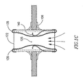
- FRM 108 may include a shunt 122 , and a cap, valve opening, valve stem, or other mechanism 175 , which may be configured to be constantly ajar at opening 125 to enable a continuous blood flow through shunt 122 .
- Cap 175 may be coupled to a spring 177 or other suitable pressure sensitive mechanism.
- spring 177 may be pre-loaded with a selected tension to respond in a controlled way to changes in one or more pressure thresholds.
- FRM 108 may include one or more cap motion limiters 179 .
- FRM 108 may include a fixed polarized magnet 181 and an electromagnetic coil 183 that includes one or more conductors 185 .
- Cap 175 may be opened and/or closed in response to changes in pressure differences between the heart chambers and/or by remotely activating magnet 181 and/or magnetic coil 183 .
- magnet 181 when magnet 181 is activated cap 175 may be further opened, and when coil 183 is activated cap 175 may be further closed.
- FRM 108 may include a shunt 122 , and a cap 175 , which may be configured to be constantly ajar at opening 125 to enable a continuous blood flow through tube 122 .
- Cap 175 may be connected to shunt 122 by a connection arm 185 .
- Cap 175 may include cuts, slots, grooves or slits etc. 187 to enable a continuous blood flow through shunt 122 .
- Slots 187 may be of different sizes, depths, widths, or densities, which may help dictate whether various areas of cap 175 are to be stronger and less flexible or weaker and more flexible, and may therefore respond differently to changes in pressure differences between the bodily lumens.
- the area may be relatively weak and flexible, thereby allowing cap 175 to be at least partially opened by a relatively low pressure blood flow through shunt 122 .
- the area may be relatively strong or less flexible, thereby only allowing cap 175 to be at least partially opened by a relatively high pressure blood flow through shunt 122 .
- FRM 108 may include a shunt 122 , and a cap 175 , which may be configured to be constantly ajar at opening 125 to enable a continuous blood flow through shunt 122 .
- Cap 175 may be coupled to a spring 190 or other suitable pressure sensitive mechanism.
- Spring 190 and cap 175 may be connected to a piston or pump mechanism 192 .
- cap 175 may be opened and/or closed in response to changes in pressure differences between the heart chambers and/or by piston 192 activating spring 190 to extend and/or distend cap 175 , thereby changing the size of opening(s) 125 .
- the usage of DPRD 101 may enable generation of a pressure curve related to the relationship between the change in pressure difference between two lumens, the flow through the flow control mechanism and the orifice area. Any required or selected design parameters may be used.
- FIG. 1J illustrates an example of such a pressure curve.
- the opening or orifice size may be relatively stable, and flow may be influenced substantially by the pressure difference.
- pressure difference rises above approximately 12 mmHg until approximately 20 mmHg the flow may increase at a higher rate, as it may now be influenced by both the increase in orifice area and the increase in pressure difference.
- pressure difference rises above approximately 20 mmHg the flow rate increase at a slower rate, since the orifice area may have already reached its maximum cross-section, and the flow may be influenced substantially by the pressure difference.
- Pressure differences and/or may be effected by linear and/or non-linear changes in the orifice area.
- Other pressure difference, flow and/or orifice area levels, relationships, and interrelationships may be used, as may other parameters, variables, minimum and maximum limits etc.
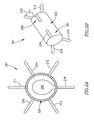
- FIGS. 2A and 2B schematically illustrate a cross-section view and a side view, respectively, of an adjustable DPRD 201 in accordance with an exemplary embodiment of the invention.
- DPRD 201 may include, for example, a frame 220 connected to one or more support arms, e.g., arms 211 - 216 .
- Frame 220 may include, for example, a flexible fixation frame, ring or tube.
- Frame 220 may be formed from a flexible material, for example, a flexible metal, super elastic alloy, and/or a shape-memory material, e.g., Nitinol or other suitable materials.
- DPRD 201 is described herein as having six arms or appendages 211 - 216 , for exemplary purposes, embodiments of the present invention are not limited in this regard and may include a different number of arms, for example, one arm, two arms, ten arms, or the like.
- Arms or appendages 211 - 216 may be flexible and/or may be pre-shaped to achieve a desired functionality.
- arms 211 - 216 may be folded during an insertion process, e.g., inside a suitable delivery tube.
- arms 211 - 216 may be formed of a super elastic material, for example, a Shape-Memory Alloy (SMA), e.g., nickel-titanium (NiTi) alloy.
- SMA Shape-Memory Alloy
- NiTi nickel-titanium
- Other suitable materials may include, for example, metals, stainless steel, and/or other suitable materials.
- At least part of arms 211 - 216 or other selected elements of DPRD 201 may be coated and/or textured to increase their bio-compatibility and/or to increase the degree to which these elements may become selectively endothelialized, as may be desired in some implantation conditions.
- DPRD 201 may include, for example, a FRM 250 , for example, including a cover, valve opening, valve stem, or other flow regulation mechanism with one or more pre-set positions, to selectively cover an orifice resulting from the deployment of DPRD 201 .
- FRM is described in detail below.
- DPRD 201 may have two sides, which may be referred to herein as a proximal side 251 and a distal side 252 , respectively.
- DPRD 201 may be implanted in heart 109 , such that the proximal side 251 of DPRD 201 may face the right atrium 103 , and the distal side 252 of DPRD 201 may face the left atrium 102 .
- Other orientations of sides 251 and 252 may be used, as may other numbers of sides.
- the distal side 252 of DPRD 201 may be connected to a distal set of arms or appendages, e.g., arms 211 - 213
- the proximal side 251 of DPRD 201 may be connected to a proximal set of arms or appendages, e.g., arms 214 - 216 .
- the distal set of arms 211 - 213 may first be discharged in the left atrium 102 , e.g., to the right of septum 105 in FIG. 1 , thus supporting DPRD 201 to the left side, from the patient's perspective, of septum 105 .
- the proximal set of arms 214 - 216 may be discharged in the right atrium 103 , e.g., to the left of septum 105 in FIG. 1 , thus supporting the right side, from the patient's perspective, of septum 105 .
- arms 211 - 216 may support frame 220 of DPRD 201 at a desired position between the left atrium 102 and the right atrium 103 .
- DPRD 301 may include, for example, a frame 302 connected to one or more arms or appendages, for example, arms 303 and 304 .
- Frame 302 may include, for example, a flexible fixation frame formed from a flexible material, for example, a flexible metal, e.g., Nitinol or Nitinol wire.
- Frame 302 may have a generally helical shape, for example, as schematically illustrated in FIG. 3 , and may be integrally formed with curved arms 303 and 304 at either end of frame 302 , as schematically illustrated in FIG. 3 .
- Other suitable shapes may be used.
- Arms 303 and 304 may be flexible and may be pre-shaped to achieve a desired functionality.
- arms 303 and 304 may be folded during an insertion process, e.g., inside a suitable delivery tube, in order to be subsequently discharged for positioning the frame 302 in a puncture.
- DPRD 301 may include a FRM 350 , for example, a FRM as detailed herein.
- FIG. 4 schematically illustrates a DPRD 401 including a DPRD 450 in accordance with an exemplary embodiment of the invention.
- DPRD 450 may be an example of FRM 250 or FRM 350 .
- DPRD 450 is shown in conjunction with a DPRD 401 which may be similar to DPRD 201 , although DPRD 450 may be used in conjunction with DPRD 301 or any other suitable shunts or medical devices.
- DPRD 450 may include, for example, a disk 432 connected to a ring 431 by a spring 433 .
- Disk 432 may be formed of a bio-compatible material, for example, pyrolitic carbon or stainless steel.
- Spring 433 may include one or more swivel springs, twisting springs, or any other spring elements, which may hold disk 432 inside ring 431 when there is substantially no pressure differential between the two sides of DPRD 401 , e.g., between the proximal side 251 and the distal side 252 of DPRD 201 of FIG. 2B .
- disk 432 may move away from the atrium having the relatively higher pressure, typically the left atrium, bending spring 433 which may apply a counterforce to the movement of disk 432 , thereby opening and/or enlarging a cavity through which blood may pass.
- the counterforce applied by spring 433 may depend on the pressure differential between the two sides of DPRD 401 , for example when the pressure in an atrium forces spring 433 to contract, such that the higher the pressure differential across DPRD 401 , the larger the opening to allow relief of such pressure differential by flow from the high pressure side to the low pressure side.
- the pressure differential between the proximal and distal sides of DPRD 401 may be controlled in accordance with one or more selected levels.
- the various configurations for DPRDs described herein may allow for opening sizes or flow rates that vary continuously with pressure differentials.
- disk 432 may be fully closed, or in addition may not entirely block the flow of blood through DPRD 450 , for example, through the area between disk 432 and ring 431 .
- disk 432 may be selectively set with a gap between ring 431 and disk 432 , such that disk 432 may function as a leaking valve to enable blood to continuously flow through a puncture.
- the continual freedom of flow across DPRD 401 may, for example, prevent blood clotting and/or thrombus formation in and/or around disk 432 .
- ring 432 may be asymmetric, for example, ring 432 may have a relatively wider upper section 451 and a relatively narrower lower section 452 . This may allow, for example, blood passage at a relatively small flow-rate during tilting of disk 432 under increased pressure, until disk 432 bends beyond the upper section of ring 431 , thereby providing a pressure or pressure differential threshold at which the valve opens or begins to open, to increase the blood flow cross-section through the vessel.
- the pressure threshold may be a continual (e.g., infinitely variable) set of pressure points at which the valve opens or allows a pressure flow in accordance with the pressure.
- valve may remain closed or slightly ajar until a certain pressure, then above that pressure open continually until an upper pressure is reached, at which the valve is fully open.
- an asymmetric ring 432 or other asymmetric components may be used to achieve similar functionality in various other FRMs, DPRDs, shunts and/or devices in accordance with embodiments of the present invention.
- ring 431 may be formed of, for example, a suitable metal. In some embodiments, ring 431 may be integrated within frame 220 , or ring 431 and frame 220 may be implemented using an integrated ring-frame component. Ring 431 and/or frame 220 may be formed of a suitable wire or tube. Ring 431 and/or arms 211 - 216 may be formed of a suitable wire or tube, e.g., the same wire or tube and/or the same material.
- FIG. 5 schematically illustrates DPRD 401 implanted in heart 109 , incorporating DPRD 450 in an open state in accordance with an exemplary embodiment of the present invention.
- a pressure difference may exist between left atrium 102 and right atrium 103 , for example, the pressure in left atrium 102 may be larger than the pressure in right atrium 103 .
- the pressure difference may cause disk 432 to move towards right atrium 103 and bend the spring 433 , thereby creating an enlarged opening through which more blood may flow from left atrium 102 to right atrium 103 .
- the pressure in left atrium 102 may decrease and the pressure in the right atrium may increase, thereby reducing the pressure difference between the left atrium 102 and the right atrium 103 , and allowing spring 433 to pull back disk 432 towards a closed or substantially closed position.
- Other mechanisms to enable disk 432 to move may be used.
- FIG. 6 schematically illustrates a DPRD 650 in accordance with another exemplary embodiment of the invention.
- DPRD 650 may be an example of FRM 108 , FRM 250 or FRM 350 .
- DPRD 650 may include, for example, ring 431 and a pre-shaped wire 634 .
- Wire 634 may include a flexible metal wire, for example, formed of Nitinol or other suitable materials.
- wire 634 may be curved to a shape of a horse-shoe or tongue or another suitable shape.
- an end of wire 634 may be attached to ring 431 , or wire 634 and ring 431 may be formed of the same wire, tube or other suitable material.
- Wire 634 may be covered by or connected to a cover or sheet 635 , which may include, for example, a flat sheet of bio-compatible material, for example, a biological tissue material used in conjunction with artificial valve leaflets. Sheet 635 may be attached to wire 634 , for example, using one or more stitches 636 .
- DPRD 650 may be included in, for example, DPRD 201 or DPRD 301 , implanted in heart 109 .
- a pressure difference may exist between left atrium 102 and right atrium 103 , for example, the pressure in left atrium 102 may be larger than the pressure in right atrium 103 .
- the pressure difference may cause sheet 635 to move, utilizing the elasticity of wire 634 , thereby creating a cavity through which blood may flow from left atrium 102 to right atrium 103 .
- the pressure in left atrium 102 may decrease and the pressure in the right atrium may increase, thereby reducing the pressure difference between the left atrium 102 and the right atrium 103 , and allowing sheet 635 to move back towards a closed or substantially closed position or towards a position wherein sheet 635 is in a marginally opened position.
- sheet 635 may not entirely block a blood flow through DPRD 650 , for example, through the area around sheet 635 , or between sheet 635 and ring 431 . This may, for example, prevent blood clotting and/or thrombus formation in and/or around sheet 635 or DPRD 650 .
- the opening or valve may be completely closed at certain pressure differentials.
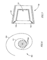
- FIG. 7 schematically illustrates a FRM 750 in accordance with another exemplary embodiment of the invention.
- FRM 750 may include, for example, ring 431 connected to a cone 737 using one or more springs 738 .
- Cone 737 may be positioned inside ring 431 , and may be formed of, for example, a bio-compatible material, e.g., pyrolitic carbon or stainless steel.
- Cone 737 may have a suitable shape, for example, rectangular, square-shaped, circular, oval, trapezoid-shaped, cone-shaped, or other suitable shapes.
- FRM 750 may be included in a shunt, e.g., DPRD 201 or DPRD 301 , implanted in heart 109 .
- Springs 738 may include one or more compression springs, and may hold cone 737 inside ring 431 , for example, when substantially no pressure difference exists between left atrium 102 and right atrium 103 .
- FRM 750 may allow blood flow from left atrium 102 to right atrium 103 .
- the pressure difference may cause cone 737 to move back against springs 738 , thereby opening or enlarging a cavity through which blood may flow from left atrium 102 to right atrium 103 .
- the pressure in left atrium 102 may decrease and the pressure in the right atrium may increase, thereby reducing the pressure difference between the left atrium 102 and the right atrium 103 , and allowing cone 737 to move back towards a closed or substantially closed position.
- cone 737 may not entirely block a blood flow through FRM 750 , for example, through the area around cone 737 , or between cone 737 and ring 431 . This may, for example, prevent blood clotting and/or thrombus formation in and/or around cone 737 or FRM 750 .
- FIG. 8 schematically illustrates a FRM 850 in accordance with another exemplary embodiment of the invention.
- FRM 850 may include, for example, a flexible valve 839 connected to and positioned inside ring 431 .
- Valve 839 may be formed of, for example, a bio-compatible material, e.g., polyurethane or silicone.
- Valve 839 may be attached to ring 431 , for example, by gluing or stitching a base 840 of valve 839 inside ring 431 .
- Valve 839 may include one or more leaflets, for example, leaflets 841 and 842 able to move and create or enlarge an opening 843 .
- the size of opening 843 may be in relation to a pressure applied to leaflets 841 and 842 .
- FRM 850 may be included in a shunt, tube or conduit, e.g., DPRD 201 or DPRD 301 , implanted in heart 109 .
- FRM 850 may allow blood flow from left atrium 102 to right atrium 103 .
- the pressure difference may stretch, spread or push leaflets 841 and/or 842 , thereby increasing the distance between them and enlarging the opening 843 , through which blood may flow from left atrium 102 to right atrium 103 .
- the pressure in left atrium 102 may decrease and the pressure in the right atrium may increase, thereby reducing the pressure difference between the left atrium 102 and the right atrium 103 , and allowing leaflets 841 and/or 843 to move back towards a closed or substantially closed position.
- valve 839 and leaflets 841 and 842 may not entirely block a blood flow through FRM 850 , for example, through the opening 843 . This may, for example, prevent blood clotting and/or thrombus formation in and/or around valve 839 or FRM 850 .
- FIG. 9 schematically illustrates a DPRD 950 within heart 109 , in accordance with another exemplary embodiment of the invention.
- DPRD 950 may include a plurality of balloons or sacs inter-connected through one or more tubes, for example, a non-compliant balloon 943 connected through a tube 944 to a compliant balloon 945 .
- the non-compliant balloon 943 may be placed in the left atrium 102 and/or in a puncture, and the compliant balloon 945 may be placed in the right atrium 103 .
- balloons 943 and/or 945 may be may be attached to a ring (e.g., ring 431 ).
- balloons 943 and/or 945 may contain a liquid 920 .
- Liquid 920 may flow from balloon 943 to balloon 945 or vice versa, for example, in relation to a pressure difference between the left atrium 102 and the right atrium 103 .
- liquid 920 may flow from non-compliant balloon 943 through tube 944 to compliant balloon 945 , thereby deflating the non-compliant balloon 943 and inflating the compliant balloon 945 .
- compliant balloon 945 may be more flexible than non-compliant balloon 943 , allowing the compliant balloon 945 to act as a spring mechanism to control the deflating of the non-compliant balloon 943 .
- FIG. 10 schematically illustrates a DPRD 1050 in accordance with another exemplary embodiment of the invention.
- DPRD 1050 may include, for example, ring 431 and a flexible disk 1046 having a hole 1047 .
- hole 1047 may be substantially circular and may be located, for example, substantially in the center of flexible disk 1046 .
- Flexible disk 1046 may be formed of, for example, a flexible polymetric material, e.g., silicone rubber or polyurethane.
- DPRD 1050 may be implanted in heart 109 , and hole 1047 may change its diameter in relation to a pressure difference between the left atrium 102 and the right atrium 103 .
- the pressure difference may push backwards or stretch the flexible disk 1046 , thereby enlarging the hole 1047 and allowing a larger area through which blood may flow from the left atrium 102 to the right atrium 103 .
- hole 1047 may still be open and may have a relatively small diameter, and flexible disk 1046 may not entirely block a blood flow through DPRD 1050 . This may, for example, prevent blood clotting and/or thrombus formation in and/or around DPRD 1050 .
- FIG. 11 schematically illustrates a DPRD 1150 in accordance with another exemplary embodiment of the invention.
- DPRD 1150 may include, for example a balloon or sac 1148 such as a non-compliant balloon containing a liquid 1120 .
- the balloon 1148 may be placed or connected inside a ring 1131 , which may include, for example, a ring similar to ring 431 and/or a frame.
- a tube 1149 may connect balloon 1148 to a reservoir 1155 , which may include one or more pistons 1151 able to move against one or more compression springs 1152 .
- Springs 1152 may be formed of, for example, metal or a suitable elastic material.
- DPRD 1150 may be implanted in heart 109 , and balloon 1148 may change its volume in relation to a pressure difference between the left atrium 102 and the right atrium 103 .
- the pressure difference may push or deflate the balloon 1148 , thereby causing liquid 1120 to flow from balloon 1148 to reservoir 1155 .
- This may create or enlarge an opening inside ring 1131 , through which blood may flow from the left atrium 102 to the right atrium 103 .
- FIG. 12 schematically illustrates a DPRD 1250 in accordance with another exemplary embodiment of the invention.
- DPRD 1250 may include, for example a balloon 1148 such as a non-compliant balloon containing a liquid 1120 .
- the balloon 1148 may be placed or connected inside a ring 1131 , which may include, for example, a ring similar to ring 431 and/or a frame.
- a tube 1149 may connect balloon 1148 to a reservoir 1155 , which may include one or more pistons 1151 able to move.
- the piston 1151 may be moved, for example, using a motor 1153 , which may include an electric motor, e.g., a step motor or other suitable motors.
- Motor 1153 may move, push or pull pistons 1151 , thereby causing liquid 1120 to flow from balloon 1148 to reservoir 1155 or vice versa. This may change the volume of balloon 1148 , thereby increasing or decreasing a size of an opening inside ring 1131 , through which blood may flow from the left atrium 102 to the right atrium 103 .
- the DPRD may be actively controlled, for example, by a patient or medical service provider.
- DPRD may be operated using external and/or manually provided instructions.
- motor 1153 may operate in accordance with external and/or manually provided instructions. Additionally or alternatively, motor 1153 may operate in relation to a pressure difference between the left atrium 102 and the right atrium 103 .
- a pressure-dependent close loop 1260 may be used, incorporating one or more pressure transducers 1254 .
- the pressure transducers 1254 may measure an absolute pressure in one or more heart chambers, for example, in left atrium 102 and/or right atrium 103 , or may measure a differential pressure between two heart chambers, for example, between left atrium 102 and right atrium 103 . Based upon the pressure information, motor 1153 may operate and move, push or pull the pistons 1151 .
- DPRD may be remotely operated using one or more of electric mechanisms, mechanical mechanisms, wireless mechanisms, pneumatic mechanisms or other suitable mechanisms.
- a wire, line, spring, pin, cable, hook, latch, motor or magnet may be connected to the DPRD to enable the DPRD to be remotely controlled by a patient and/or medical service provider.
- at least one line or control lead 1320 may connect DPRD 1300 to a control mechanism 1310 , for example, a control box.
- control lead 1320 may exit vein 1330 through a puncture or hole 1335 .
- Control mechanism 1310 may include, for example, a mechanical interface, electrical interface, pull/push wire, spring, magnet or other suitable elements or mechanisms to enable DPRD 1300 to be remotely controlled.
- Control mechanism 1310 may be a micro mechanism that may be placed internally or externally, for example, it may be sown into tissue under a patient's skin, to provide external access for a medical service provider, or it may be placed internally in proximity to a location that may be accessed by a medical service provider with a minimally invasive technique.
- DPRD 1300 may be controlled wirelessly from an external ‘transmitting’ unit.
- control signals may be delivered from outside a patient's body using telemetry, localized RF radiation, localized Ultrasound radiation, external magnetic field, localized heating and other suitable means of generating signals.
- DPRD 1300 may include a ‘receiving’ unit.
- the receiving unit may include an internal power source (e.g., a battery), or may receive its energizing power from the control signal or other transmitted signals.
- the receiving unit may be coupled to an external power source, for example, via an implanted plug, or may be directly connected to DPRD 1300 on a temporary basis (e.g., at the doctor's office), were the implanted plug may relay command signals and/or power to activate DPRD 1300 .
- control lead 1320 may be accessed by entering the patient using a conventional needle or syringe 1365 , for example by making a small incision.
- Control lead(s) 1320 may be controlled externally or internally to enable DPRD 1300 to be controlled.
- control lead(s) 1320 may operate within a tube, for example a silicon pressurized tube 1370 .
- Control mechanism 1310 may include a remote valve opening/closing mechanism, for example, to enable monitoring of heart pressure, monitoring of DPRD functioning etc.
- control mechanism 1310 may be used to monitor blood flow changes in response to valve positioning.
- Control mechanism 1310 may enable manual reduction of heart pressure or in blood pressure in certain chambers or the heart in the case of clinical need.
- Control mechanism 1310 may enable flushing or cleaning of DPRD 1300 at selected intervals, for example, by increasing internal blood pressure or fluid pressure.
- flushing or cleaning may be enabled using a flushing or cleaning fluid, for example, saline solution that may be entered into control lead 1320 at a selected pressure to cause the orifice to be cleaned or flushed. Such cleaning may help in reducing undesired growth, infections etc. associated with DPRD 1300 .
- Control mechanism 1310 may be coated with one or more substances to prevent thrombosis or other conditions.
- DPRD 1300 may include spikes, thorns or other suitable mechanisms to prevent a FRM from being in full contact with a shunt, or to ensure only minimal contact between a FRM and a shunt.
- Control mechanism 1310 may enable parts of DPRD 1300 to be remotely replaced, cleaned, serviced or otherwise manipulated.
- Control mechanism 1310 may enable a pre-configured or designed leak to be remotely opened, closed, or otherwise changed in accordance with clinical requirements.
- Control mechanism 1310 may enable blocking up of the DPRD's orifice or cavity, for example, by remotely placing a plug in the orifice to cease functioning of the DPRD.
- One or more of the above qualities may enable a health service provider to remotely control the functioning of DPRD 1300 .
- control mechanism 1310 may include one or more push knobs 1340 or other suitable controls or mechanisms that may be controlled using a finger or other suitable implement.
- the various push knobs 1340 may be pushed individually, simultaneously and/or in various other combinations to achieve a desired effect in DPRD 1300 .
- control mechanism 1310 may include, for example, one or more rods or electric conductors 1350 to help control DPRD 1300 .
- control mechanism 1310 may include, for example, one or more security mechanisms 1345 , for example, a locking button to help prevent non-required changes from being made to the operation of DPRD 1300 .
- control mechanism 1310 may include one or more springs or other suitable control mechanisms coupled to rod 1350 and DPRD 1300 .
- control mechanism 1310 may be used to control DPRD 1300 , for example using one or more rods or wires 1375 etc., optionally operating within tube 1370 .
- DPRD 1300 may include a cover 1377 , for example, flexible or non-flexible cover, which may be left constantly ajar, for example, to form gap 1379 .
- cover 1377 may be constructed from a rigid material and may be assembled or connected in a rigid manner to a locking mechanism 1380 . Once cover 1377 has been set in a selected position by locking mechanism 1380 , it may remain stable, for example, not being affected by blood pressure changes, until cover 1377 is re-positioned. In such a case, cover 1377 may only be adjusted by intentional and controlled actions using control mechanism 1310 , for example, wires 1375 using signals, or other suitable communication links.
- Locking mechanism 1380 may enable cover 1377 to be remotely set in one or more positions.
- Locking mechanism 1380 may include, for example, one or more of a spring, latch, lever, notch, slot, hook, slide or other suitable locking mechanism(s).
- position # 1 may be a lower position, for example where the hook 1325 fastens onto the catching mechanism 1332 as indicated;
- position # 2 may be a medium position, for example where the hook 1325 fastens onto the catching mechanism 1333 ;
- position # 3 may be a higher position for example where the hook 1325 fastens onto the catching mechanism 1334 .
- Other settings, opening sizes, flow levels, positions and numbers of positions may be used.
- Control mechanism 1310 may include security features, for example, to help prevent unauthorized personnel from activating DPRD 1300 (e.g., special tools and magnets, coded sequence, password etc).
- control mechanism 1310 may be used to control DPRD 1300 , for example using an auxiliary hydraulic system.
- DPRD 1300 may be connected to the hydraulic system, for example, via one or more tubes 1390 that may help control the pressures and/or flow rates of fluids delivered through DPRD 1390 .
- DPRD 1390 may be connected to the hydraulic system when required, or may be permanently attached to the hydraulic system.
- tubing 1390 may increase the fluid pressure in DPRD 1300 , for example, to provide significant force on or inside the shunt.
- Tubing 1390 may additionally or alternatively be used for “maintenance”, for example, by forcing liquid through the shunt, for example, via shunt base 1392 , to flush, clean and/or lubricate the shunt and/or FRM 1396 , and/or to release moving parts in DPRD 1300 in order to keep DPRD 1300 in a required operating condition or state.
- a substance e.g., saline solution
- tubing 1390 may additionally or alternatively be used for “maintenance”, for example, by forcing liquid through the shunt, for example, via shunt base 1392 , to flush, clean and/or lubricate the shunt and/or FRM 1396 , and/or to release moving parts in DPRD 1300 in order to keep DPRD 1300 in a required operating condition or state.
- a substance e.g., saline solution
- tubing 1390 may additionally or alternatively be used for “maintenance”, for example, by forcing liquid through the
- Piston diaphragm 1394 may be extended and/or distended thereby causing FRM 1396 to be manipulated, for example, to open and/or close FRM 1396 , to allow fluid to selectively flow through DPRD 1300 .
- Tube 1390 may be connectable to tube 1320 (see FIGS. 13A and 13B ) and/or to a needle 1366 or other suitable device for penetrating a patient's skin to connect to tube 1390 .
- the hydraulic mechanism may be used after deployment of DPRD 1300 in the body, for example to verify operability of DPRD 1300 .
- the hydraulic mechanism may be used when checking DPRG operability following deployment of DPRD 1300 in the body.
- some embodiments of the present invention may use one or more threshold values, pre-defined parameters, conditions and/or criteria, for example, to trigger an activation or a de-activation of a shunt, a DPRD or a FRM.
- the pressure regulation device may be delivered and implanted in a patient's body using a minimally invasive procedure, for example, using percutaneous delivery.
- the device may be mounted on a catheter delivery system and inserted to the body via small incision. Once the device is in the correct location inside the body, it may be deployed by an operator, expanded and locked in place.
- a device that is delivered on a catheter may be, for example, contracted or folded into a small dimension, and the device may self-expand upon deployment.
- the pressure regulation may be delivered using invasive surgery, for example where a surgeon makes a larger opening in the body in order to achieve more direct contact with the device implantation location.
- a transseptal needle set may be advanced toward the wall of the right atrial septum. Access may be made from the femoral vein with the apparatus being advanced through the inferior vena cava and into the right atrium. Once transseptal puncture has been achieved, a guidewire may be exchanged for a needle component and then passed into the left atrium.
- the dilator and wire may subsequently be withdrawn from the sheath that may now extend from the femoral vein access point in the patient's groin to the left atrium, traversing the femoral vein, the illiac vein, the inferior vena cava, the right atrium, and the atrial septum etc.
- the delivery catheter may be passed through the sheath while under fluoroscopic visualization. Radiopaque markers may be provided on this catheter as well as the sheath in order to locate specific points.
- the delivery catheter may be carefully and slowly advanced so that the most distal portion of the left-atrial fixation element is emitted from the distal opening of the catheter and into the chamber of the left atrium.
- the fixation elements may be formed from a spring-like material and/or may be a super-elastic of shape-memory alloy, so that as it leaves the constraint provided by the inner area of the delivery catheter, it reforms into its pre-configured fully formed shape.
- the assembly of the sheath and the delivery catheter may then slowly be retracted en bloc so as to withdraw the fixation elements towards the atrial septum.
- the physician may stop this retraction when it becomes apparent by fluoroscopic visualization as well as by tactile feedback that the fixation element has become seated against the atrial septum.
- the sheath alone may be retracted, uncovering the shunt and positioning it within the opening that has been created within the atrial septum.
- the sheath may then be further retracted, allowing the right-atrial fixation element to reform into its fully formed shape.
- the entire shunt assembly or DPRD may then be detached from the delivery catheter system.
- the DPRD may be controlled within the delivery catheter by means of long controller wire that has independent translational control within the catheter area.
- This attachment may be formed by any conventional method, e.g., a solder or adhesive or the like that may mechanically detach at a prescribed tension level, that level being exceeded by the physician at this point in the procedure by firmly retracting the controller wire.
- Other methods of deployment of DPRD and/or FRM may be used.
- FIG. 14 illustrates a method of delivering a DPRD and/or a FRM into a body area, for example, the septum of the heart between the left and right atrium, according to some embodiments of the present invention.
- Implantation of a device in the septum may involve one or more of the following processes: a) identifying the precise site for implantation; b) aiming the device toward the selected site; and c) ensuring accuracy and integrity of the implantation.
- the ideal implantation position may be chosen, for example, by a medical professional, for example, by imaging the septum and analyzing the septum anatomy (e.g., by TEE).
- the aiming may include identifying the precise device delivery tool location using known tools for ‘mapping’ the septum site.
- Markers may be added to the delivery tools and devices (e.g., gold markers).
- the medical professional may check and test the device installation, optionally before full retrieval of the delivery system. For example, the medical professional may use direct contact such as physically challenging or pulling the entire device (e.g., by pulling gently on the device to ensure proper anchoring).
- the anchoring may be tested by non-contact means (e.g., using electromagnetic imaging, Echo, x-ray, angiography with contrast material etc.).
- a DPRD may be implanted between two or more chambers, lumens, organs, regions, zones etc. in a body, for example, using a catheter.
- a FRM may be deployed in a selected setting or position, for example, to enable a continuous flow of fluid between two or more lumens, and to be selectively activated or de-activated in accordance with changes in pressure differences between the lumens.
- the FRM may be controlled (e.g., passively) in response to changes in pressure differences between the lumens, for example, FRM may be further opened and/or closed in response to a pressure change.
- the DPRD and/or FRM may be remotely controlled to help control the flow of fluids between the lumens.
- the remote control of the DPRD and/or FRM may enable cleaning the DPRD and/or FRM, disabling the DPRD and/or FRM, changing elements of the DPRD and/or FRM etc. Any combination of the above steps may be implemented. Further, other steps or series of steps may be used.
Landscapes
- Health & Medical Sciences (AREA)
- Life Sciences & Earth Sciences (AREA)
- Cardiology (AREA)
- Heart & Thoracic Surgery (AREA)
- Engineering & Computer Science (AREA)
- Veterinary Medicine (AREA)
- Public Health (AREA)
- General Health & Medical Sciences (AREA)
- Animal Behavior & Ethology (AREA)
- Biomedical Technology (AREA)
- Surgery (AREA)
- Vascular Medicine (AREA)
- Molecular Biology (AREA)
- Medical Informatics (AREA)
- Nuclear Medicine, Radiotherapy & Molecular Imaging (AREA)
- Oral & Maxillofacial Surgery (AREA)
- Transplantation (AREA)
- Pathology (AREA)
- Biophysics (AREA)
- Physics & Mathematics (AREA)
- Physiology (AREA)
- Anesthesiology (AREA)
- Hematology (AREA)
- Ophthalmology & Optometry (AREA)
- Otolaryngology (AREA)
- Mechanical Engineering (AREA)
- External Artificial Organs (AREA)
- Prostheses (AREA)
- Surgical Instruments (AREA)
Abstract
A differential pressure regulating device is provided for controlling in-vivo pressure in a body, and in particularly in a heart. The device may include a shunt being positioned between two or more lumens in a body, to enable fluids to flow between the lumens, and an adjustable flow regulation mechanism being configured to selectively cover an opening of the shunt, to regulate the flow of fluid through the shunt in relation to a pressure difference between the body lumens. In some embodiments a control mechanism coupled to the adjustable flow regulation mechanism may be provided, to remotely activate the adjustable flow regulation mechanism.
Description
The present application is a U.S. national application of PCT Application No. PCT/IL2005/00131, filed on Feb. 3, 2005. This application also claims the benefit under 119(e) of U.S. Provisional Application No. 60/541,267 filed on Feb. 3, 2004 and U.S. Provisional Application No. 60/573,378 filed on May 24, 2004, the disclosures of which are incorporated herein by reference.
The present invention relates to devices and methods for reducing or regulating pressure within a circulatory system, and in particular to regulate blood pressure in a heart.
CHF is recognized as one of the most common causes of hospitalization and mortality in Western society, and has a great impact on the quality of life. CHF is a disorder characterized by low systemic perfusion and inefficient cardiac function. CHF causes may include myocardial insult due to ischemia, cardiomyopathy and other processes. Pathophysiologic mechanisms that are directly associated with CHF include reduced cardiac output, increase in cardiac filling pressures, and fluid accumulation, which may lead to, for example, pulmonar congestion and dyspnea. Impairment of systolic function may result in poor left ventricular contraction and reduced cardiac output, which may generate clinical symptoms including effort intolerance, dyspnea, reduced longevity, edema (lung or peripheral) and pain. A patient with systolic dysfunction may usually have a larger left ventricle because of phenomena called cardiac remodeling aimed to maintain adequate stroke-volume. This pathophisiologic mechanism is associated with increased atrial pressure and left ventricular filling pressure. With abnormal diastolic function, the left ventricle may be stiff and markedly less compliant partly because of abnormal relaxation leading to inadequate cardiac filling at normal pressures. Maintenance of adequate cardiac filling at higher filling pressures may be needed to maintain cardiac output. This mandatory rise of filling pressure to maintain cardiac filling and output may lead to pulmonary venous hypertension and lung edema.
Presently available treatments for CHF fall into three generally categories: (1) pharmacological, e.g., diuretics; (2) assist systems, e.g., pumps; and (3) surgical treatments. With respect to pharmacological treatments, vasodilators have been used to reduce the workload of the heart by reducing systemic vascular resistance and diuretics to prevent fluid accumulation and edema formation, and reduce cardiac filling pressure.
Assist devices used to treat CHF may include, for example, mechanical pumps. Mechanical pumps reduce the load on the heart by performing all or part of the pumping function normally done by the heart. Currently, mechanical pumps are used, for example, to sustain the patient while a donor heart for transplantation becomes available for the patient. There are also a number of pacing devices used to treat CHF. Resysnchronization pacemakers have also been used to treat CHF. Finally, there are at least three extremely invasive and complex surgical procedures for treatment of heart failure: 1) heart transplant; 2) dynamic cardiomyoplasty; and 3) the Batista partial left ventriculectomy.
In extreme acute situations, temporary assist devices and intraaortic balloons may be helpful. Cardiac transplantation and chronic left ventricular assist device (LVAD) implants may often be used as last resort. However, all the assist devices currently used are intended to improve pumping capacity of the heart and increase cardiac output to levels compatible with normal life, reducing filling pressures and/or preventing edema formation. Finally, cardiac transplantation may be used to treat extreme cardiac dysfunction cases, however this procedure is highly invasive and is limited by the availability of donor hearts. The mechanical devices may allow propulsion of significant amount of blood (liters/min) and this is also their main limitation. The need for power supply, relatively large pumps and possibility of hemolysis and infection are all of concern.
The subject matter regarded as the invention is particularly pointed out and distinctly claimed in the concluding portion of the specification. The invention, however, both as to organization and method of operation, together with features and advantages thereof, may best be understood by reference to the following detailed description when read with the accompanied drawings in which:
It will be appreciated that for simplicity and clarity of illustration, elements shown in the figures have not necessarily been drawn to scale. For example, the dimensions of some of the elements may be exaggerated relative to other elements for clarity. Further, where considered appropriate, reference numerals may be repeated among the figures to indicate corresponding or analogous elements.
The present invention may provide methods and devices for regulating pressure in a body. According to some embodiments of the present invention, a differential pressure regulating device may include a shunt being positioned between two or more lumens in a body, to enable fluids to flow between the lumens, and an adjustable flow regulation mechanism being configured to selectively cover an opening of the shunt, to regulate the flow of fluid through the shunt in relation to a pressure difference between the body lumens.
According to some embodiments the pressure regulating device may include a shunt being positioned between two or more chambers in a heart, to enable fluids to flow between the chambers, an adjustable flow regulation mechanism being configured to selectively cover the opening of the shunt, to regulate the flow of fluid through the shunt, and a control mechanism to be coupled to the adjustable flow regulation mechanism, to remotely activate the adjustable flow regulation mechanism.
In another embodiment a method is provided to control in-vivo pressure, which may include implanting a differential pressure regulation device in a body, the pressure regulation device including a shunt placed between two or more lumens in a body, deploying a flow regulation mechanism, and controlling the flow regulation mechanism setting according to changes in pressure differences between the lumens.
In a further embodiment of the present invention a method is provided to control in-vivo pressure, which may include controlling a flow regulation mechanism flow setting using a control mechanism implanted in a body, the flow regulation mechanism being disposed within a differential pressure regulation device that includes a shunt placed between two or more lumens, for example, between a left atrium of a heart and a right atrium of a heart.
In the following detailed description, numerous specific details are set forth in order to provide a thorough understanding of the invention. However, it will be understood by those of ordinary skill in the art that the present invention may be practiced without these specific details. In other instances, well-known methods, procedures, components and structures may not have been described in detail so as not to obscure the present invention.
It will be appreciated that although part of the discussion herein may relate, for exemplary purposes, to a heart, heart chambers and/or heart atriums, embodiments of the present invention are not limited in this regard, and may be used in conjunction with various other vessels, lumens, organs or body sites. For example some embodiments of the present invention may include regulating fluid transfer between cavities in the brain, between selected organs, between blood vessels (e.g., between the aorta and the vena-cava) etc., and/or between other suitable lumens, for example, zones, cavities, organs, vessels, regions or areas in a body.
Some embodiments of the present invention include, for example, a method and apparatus for controlling in-vivo pressure by reducing or otherwise controlling pressure differences between two or more body sites, for example, two chambers of the human heart (e.g., the left atrium and the right atrium). For example, such pressure control may be used to help solve the problem of increased cardiac filling pressure in patients with congestive heart failure and predominantly diastolic dysfunction, thereby helping to minimize or prevent pulmonary fluid accumulation, edema formation and clinical complaint of dyspnea. In another example the pressure control may be used to reduce left ventricle filling pressure. Some embodiments of the invention may include a Differential Pressure Regulation Device (DPRD), for example, including a shunt, tube or other structure having an orifice, tube or opening to fluidically connect two or more lumens, for example, to connect a left atrium of a heart with a right atrium of the heart. In accordance with some embodiments of the invention, the DPRD may include an adjustment mechanism or a regulation mechanism, able to adjust, modify or otherwise regulate, for example the cross-sectional area of the orifice, for example, in relation to a change in pressure difference between the first and second lumens, for example, such as to increase and/or decrease the flow-rate of blood between the two lumens.
Some embodiments of the present invention may be used, for example, to unload an excessive filling pressure of a left heart ventricle in a Congestive Heart Failure (CHF) patient, and to potentially prevent or reduce the occurrence of pulmonary edema.
Some embodiments of the present invention include, for example, implanting an adjustable DPRD in a wall between two heart chambers, e.g., between the left atrium and the right atrium. The pressure regulation device may, for example, allow a selective volume of blood to flow from the left atrium to the right atrium, in relation to the change in pressure difference between the left atrium and the right atrium. The pressure regulation device may, for example, be adjusted to selectively change the size or shape of the opening, amount of blood allowed to flow through, etc.
In some embodiments, the pressure regulation device may be configured to maintain a continual flow between two or more lumens, for example, between the left atrium and the right atrium. For example, a shunt, tube or other structure may be coupled to a cover, valve opening, valve stem, or other flow regulation mechanism that may be configured to be continually ajar, to enable a selected minimal quantity of fluid to continually flow between two lumens in a body, for example, between the heart chambers. The cover may be subsequently adjusted, for example may be further opened and/or closed, to control the quantity of fluid flow between the lumens. The fluid flow through the DPRD may increase or decrease in accordance with changes in the pressure or pressure difference between the two lumens. For example, cover may be opened and/or closed as the pressure in the left atrium increases or decreases relative to the pressure in the right atrium. In some embodiments the DPRD may be configured such that the orifice cover has no direct contact with the shunt opening to reduce help minimize or prevent tissue growth on or around the orifice cover. Such a configuration may enable a continuous fluid flow through the DPRD, and may help to prevent or reduce the occurrence of clotting or formation of biofilm or other unwanted growths. In some embodiments the DPRD may be used to flush or clean out the shunt and/or shunt cover etc.
Reference is made to FIG. 1A , which schematically illustrates a DPRD 101 implanted in a heart 109, in accordance with an exemplary embodiment of the present invention. DPRD 101 may be implanted between two or more body lumens, for example, between a left atrium 102 and a right atrium 103 of heart 102. DPRD 101 may be implanted in other heart chambers, using different arrangements of heart chambers, and/or in or between other body lumens. In some embodiments, an opening, puncture or other structure may be formed in a wall between two body lumens, for example, in septum 105 between left atrium 102 and right atrium 103, for example, using a puncturing or cutting device mounted to the distal end of a catheter or any other suitable puncturing mechanism. DPRD 101 may then be placed in a puncture using a catheter or another suitable delivery mechanism. In some embodiments, one or more tissue fixation elements, for example, support arms 106 may support DPRD 101 at a desired position in a generated hole or puncture.
In some embodiments, below a certain pressure or pressure differential, the valve or device may be fully closed; however in other embodiments, below a certain pressure or pressure differential, the valve may be not fully closed or slightly ajar. For example, the valve may have a minimum opening size.
In some embodiments, one or more properties of the DPRD, for example, the size of the cross-section opening of the pressure regulation device, may be dependent on the blood pressure difference between the left atrium and the right atrium. Therefore, in some embodiments, the blood flow between the left atrium and the right atrium may be influenced by the change in blood pressure difference between the left atrium and the right atrium.
A DPRD according to some embodiments of the invention may allow for a reduction in ventricular pressure by reducing pressure in an atrium of the heart.
In some embodiments, a DPRD may be used for Atrium Septum Defect (ASD) patients, for example who may not be able to tolerate a complete uncontrolled atrium closure procedure, to selectively close a hole or gap in the septum.
In some embodiments, a DPRD may be used to transfer fluid from the left atrium to the right atrium, for example, to aid a patient with pulmonary hypertension. In such cases the DPRD may be positioned with FRM 108 in the left atrium. According to some embodiments of the present invention, FRM 108 may be unidirectional or bi-directional.
In some embodiments, a plurality of DPRD's may be implanted in a wall or other structure, for example, to help provide redundancy, to implant devices with different set ranges to achieve a higher level of opening control, and/or to enable adding of additional devices. Implanting a plurality of DPRD's may enable the delivering catheter diameter to be reduced, as two or more DPRD's of a lesser diameter may be delivered.
In other embodiments FRM 108 may include a cover, lid or other suitable mechanism that may have various forms to enable partial or total closure of FRM 108. Reference is now made to FIGS. 1B-1G . In FIG. 1B FRM 108 may include two or more arms 120 which may be configured to be continuously or constantly ajar at opening 125 of shunt 122. For example, FRM 108 may be configured to remain continually at least partially detached from shunt 122, to allow a continuous flow of fluid between left atrium 102 and right atrium 103. Arms 120 may be further opened and/or closed in response to changes in pressure differences between the heart chambers. Arms 120 may be constructed from a flexible polymer or other suitable materials. Arms 120 may have rounded shapes at arm ends 130, for example, to help prevent blood stagnation.
In FIG. 1C FRM 108 may include a shunt 122, and two or more flexible membranes 135, which may be configured to be constantly ajar at opening 125 to enable a continuous blood flow through shunt 122. For example, in the various embodiments discussed herein, a device may be set so that no matter what the pressure or pressure differential between chambers, a minimum opening size may be set or flow amount may occur. Membrane 135 may include at least one spring-type mechanism, to help expand and/or contract membrane 135, in response to changes in pressure differences between the heart chambers.
In FIG. 1D FRM 108 may include a shunt 122, and one or more flexible or spring based lid, membrane or leaflets 150, optionally connected to shunt 122 by a spring or other suitable pressure sensitive mechanism 155. In one embodiment pressure sensitive mechanism 155 may be pre-loaded to respond in a controlled way to changes in one or more pressure thresholds. Lid 150 may be configured to be constantly ajar at opening 125 to enable a continuous blood flow through shunt 122. FRM 108 may include one or more raised areas 160, for example, thorn shaped objects or objects with other suitable shapes to help prevent lid 150 from making full contact with shunt 122.
In FIG. 1E FRM 108 may include a shunt 122, and one or more angled flexible membranes or leaflets 165, which may be configured to be constantly ajar at opening 125 to enable a continuous blood flow through shunt 122. In one embodiment leaflets 165 may be pre-loaded with a selected tension to respond in a controlled way to changes in one or more pressure thresholds. Leaflet 165 may include at least one spring mechanism or other suitable mechanism to help close and/or open leaflet 165 in response to changes in pressure differences between the heart chambers. Leaflet 165 may include at least one magnet or electromagnet 170 or other suitable mechanism to help remotely close and/or open leaflet 165. A conducting wire 172 or other suitable mechanism may be used to activate magnet(s) or electromagnet(s) 170.
In FIG. 1F FRM 108 may include a shunt 122, and a cap, valve opening, valve stem, or other mechanism 175, which may be configured to be constantly ajar at opening 125 to enable a continuous blood flow through shunt 122. Cap 175 may be coupled to a spring 177 or other suitable pressure sensitive mechanism. In one embodiment spring 177 may be pre-loaded with a selected tension to respond in a controlled way to changes in one or more pressure thresholds. FRM 108 may include one or more cap motion limiters 179. FRM 108 may include a fixed polarized magnet 181 and an electromagnetic coil 183 that includes one or more conductors 185. Cap 175 may be opened and/or closed in response to changes in pressure differences between the heart chambers and/or by remotely activating magnet 181 and/or magnetic coil 183. For example, when magnet 181 is activated cap 175 may be further opened, and when coil 183 is activated cap 175 may be further closed.
As shown in FIG. 1G FRM 108 may include a shunt 122, and a cap 175, which may be configured to be constantly ajar at opening 125 to enable a continuous blood flow through tube 122. Cap 175 may be connected to shunt 122 by a connection arm 185. Cap 175 may include cuts, slots, grooves or slits etc. 187 to enable a continuous blood flow through shunt 122. Slots 187 may be of different sizes, depths, widths, or densities, which may help dictate whether various areas of cap 175 are to be stronger and less flexible or weaker and more flexible, and may therefore respond differently to changes in pressure differences between the bodily lumens. For example, in an area where there are more or deeper incursions the area may be relatively weak and flexible, thereby allowing cap 175 to be at least partially opened by a relatively low pressure blood flow through shunt 122. In an area where there are fewer and/or more superficial incursions the area may be relatively strong or less flexible, thereby only allowing cap 175 to be at least partially opened by a relatively high pressure blood flow through shunt 122.
As shown in FIGS. 1H and 1I FRM 108 may include a shunt 122, and a cap 175, which may be configured to be constantly ajar at opening 125 to enable a continuous blood flow through shunt 122. Cap 175 may be coupled to a spring 190 or other suitable pressure sensitive mechanism. Spring 190 and cap 175 may be connected to a piston or pump mechanism 192. As can be seen in FIG. 1I , cap 175 may be opened and/or closed in response to changes in pressure differences between the heart chambers and/or by piston 192 activating spring 190 to extend and/or distend cap 175, thereby changing the size of opening(s) 125.
According to some embodiments of the present invention, the usage of DPRD 101 may enable generation of a pressure curve related to the relationship between the change in pressure difference between two lumens, the flow through the flow control mechanism and the orifice area. Any required or selected design parameters may be used. Reference is now made to FIG. 1J , which illustrates an example of such a pressure curve. As can be seen in FIG. 1J , below a pressure differential of 12 mmHg, the opening or orifice size may be relatively stable, and flow may be influenced substantially by the pressure difference. When pressure difference rises above approximately 12 mmHg until approximately 20 mmHg the flow may increase at a higher rate, as it may now be influenced by both the increase in orifice area and the increase in pressure difference. When pressure difference rises above approximately 20 mmHg the flow rate increase at a slower rate, since the orifice area may have already reached its maximum cross-section, and the flow may be influenced substantially by the pressure difference. Pressure differences and/or may be effected by linear and/or non-linear changes in the orifice area. Other pressure difference, flow and/or orifice area levels, relationships, and interrelationships may be used, as may other parameters, variables, minimum and maximum limits etc.
Reference is made to FIGS. 2A and 2B , which schematically illustrate a cross-section view and a side view, respectively, of an adjustable DPRD 201 in accordance with an exemplary embodiment of the invention. DPRD 201 may include, for example, a frame 220 connected to one or more support arms, e.g., arms 211-216. Frame 220 may include, for example, a flexible fixation frame, ring or tube. Frame 220 may be formed from a flexible material, for example, a flexible metal, super elastic alloy, and/or a shape-memory material, e.g., Nitinol or other suitable materials.
Although DPRD 201 is described herein as having six arms or appendages 211-216, for exemplary purposes, embodiments of the present invention are not limited in this regard and may include a different number of arms, for example, one arm, two arms, ten arms, or the like.
Arms or appendages 211-216 may be flexible and/or may be pre-shaped to achieve a desired functionality. For example, arms 211-216 may be folded during an insertion process, e.g., inside a suitable delivery tube. In some embodiments, arms 211-216 may be formed of a super elastic material, for example, a Shape-Memory Alloy (SMA), e.g., nickel-titanium (NiTi) alloy. Other suitable materials may include, for example, metals, stainless steel, and/or other suitable materials. At least part of arms 211-216 or other selected elements of DPRD 201 may be coated and/or textured to increase their bio-compatibility and/or to increase the degree to which these elements may become selectively endothelialized, as may be desired in some implantation conditions.
As illustrated schematically in FIG. 2B , DPRD 201 may have two sides, which may be referred to herein as a proximal side 251 and a distal side 252, respectively. For example, DPRD 201 may be implanted in heart 109, such that the proximal side 251 of DPRD 201 may face the right atrium 103, and the distal side 252 of DPRD 201 may face the left atrium 102. Other orientations of sides 251 and 252 may be used, as may other numbers of sides.
In some embodiments, the distal side 252 of DPRD 201 may be connected to a distal set of arms or appendages, e.g., arms 211-213, and the proximal side 251 of DPRD 201 may be connected to a proximal set of arms or appendages, e.g., arms 214-216. Thus, when DPRD 201 is implanted in heart 109, the distal set of arms 211-213 may first be discharged in the left atrium 102, e.g., to the right of septum 105 in FIG. 1 , thus supporting DPRD 201 to the left side, from the patient's perspective, of septum 105. Then, as the insertion of DPRD 201 is completed, e.g., by retracting a catheter or delivery tube carrying DPRD 201, the proximal set of arms 214-216 may be discharged in the right atrium 103, e.g., to the left of septum 105 in FIG. 1 , thus supporting the right side, from the patient's perspective, of septum 105. In this manner, arms 211-216 may support frame 220 of DPRD 201 at a desired position between the left atrium 102 and the right atrium 103.
Reference is now made to FIG. 3 , which schematically illustrates a DPRD 301 in accordance with another exemplary embodiment of the present invention. DPRD 301 may include, for example, a frame 302 connected to one or more arms or appendages, for example, arms 303 and 304.
Reference is also made to FIG. 4 , which schematically illustrates a DPRD 401 including a DPRD 450 in accordance with an exemplary embodiment of the invention. DPRD 450 may be an example of FRM 250 or FRM 350. For exemplary purposes only, DPRD 450 is shown in conjunction with a DPRD 401 which may be similar to DPRD 201, although DPRD 450 may be used in conjunction with DPRD 301 or any other suitable shunts or medical devices.
In response to a pressure differential between the two sides of DPRD 401, disk 432 may move away from the atrium having the relatively higher pressure, typically the left atrium, bending spring 433 which may apply a counterforce to the movement of disk 432, thereby opening and/or enlarging a cavity through which blood may pass. The counterforce applied by spring 433 may depend on the pressure differential between the two sides of DPRD 401, for example when the pressure in an atrium forces spring 433 to contract, such that the higher the pressure differential across DPRD 401, the larger the opening to allow relief of such pressure differential by flow from the high pressure side to the low pressure side. In this manner, the pressure differential between the proximal and distal sides of DPRD 401 may be controlled in accordance with one or more selected levels. In some embodiments the various configurations for DPRDs described herein may allow for opening sizes or flow rates that vary continuously with pressure differentials.
It will be appreciated that when there is substantially no pressure difference between the two sides of DPRD 401, or when the pressure difference is relatively small, disk 432 may be fully closed, or in addition may not entirely block the flow of blood through DPRD 450, for example, through the area between disk 432 and ring 431. For example, disk 432 may be selectively set with a gap between ring 431 and disk 432, such that disk 432 may function as a leaking valve to enable blood to continuously flow through a puncture. The continual freedom of flow across DPRD 401 may, for example, prevent blood clotting and/or thrombus formation in and/or around disk 432.
In some embodiments, ring 432 may be asymmetric, for example, ring 432 may have a relatively wider upper section 451 and a relatively narrower lower section 452. This may allow, for example, blood passage at a relatively small flow-rate during tilting of disk 432 under increased pressure, until disk 432 bends beyond the upper section of ring 431, thereby providing a pressure or pressure differential threshold at which the valve opens or begins to open, to increase the blood flow cross-section through the vessel. The pressure threshold may be a continual (e.g., infinitely variable) set of pressure points at which the valve opens or allows a pressure flow in accordance with the pressure. For example, the valve may remain closed or slightly ajar until a certain pressure, then above that pressure open continually until an upper pressure is reached, at which the valve is fully open. It is noted that an asymmetric ring 432 or other asymmetric components may be used to achieve similar functionality in various other FRMs, DPRDs, shunts and/or devices in accordance with embodiments of the present invention.
In some embodiments, ring 431 may be formed of, for example, a suitable metal. In some embodiments, ring 431 may be integrated within frame 220, or ring 431 and frame 220 may be implemented using an integrated ring-frame component. Ring 431 and/or frame 220 may be formed of a suitable wire or tube. Ring 431 and/or arms 211-216 may be formed of a suitable wire or tube, e.g., the same wire or tube and/or the same material.
Reference is also made to FIG. 5 , which schematically illustrates DPRD 401 implanted in heart 109, incorporating DPRD 450 in an open state in accordance with an exemplary embodiment of the present invention. A pressure difference may exist between left atrium 102 and right atrium 103, for example, the pressure in left atrium 102 may be larger than the pressure in right atrium 103. The pressure difference may cause disk 432 to move towards right atrium 103 and bend the spring 433, thereby creating an enlarged opening through which more blood may flow from left atrium 102 to right atrium 103. As the blood flows towards right atrium 103, the pressure in left atrium 102 may decrease and the pressure in the right atrium may increase, thereby reducing the pressure difference between the left atrium 102 and the right atrium 103, and allowing spring 433 to pull back disk 432 towards a closed or substantially closed position. Other mechanisms to enable disk 432 to move may be used.
It is noted that when there is no pressure difference between the left atrium 102 and the right atrium 103, or when the pressure difference is relatively small, sheet 635 may not entirely block a blood flow through DPRD 650, for example, through the area around sheet 635, or between sheet 635 and ring 431. This may, for example, prevent blood clotting and/or thrombus formation in and/or around sheet 635 or DPRD 650. However, as with the other configurations discussed herein, in other embodiments, the opening or valve may be completely closed at certain pressure differentials.
When a pressure difference exists between left atrium 102 and right atrium 103, for example, when the pressure in left atrium 102 is larger than the pressure in right atrium 103, FRM 750 may allow blood flow from left atrium 102 to right atrium 103. The pressure difference may cause cone 737 to move back against springs 738, thereby opening or enlarging a cavity through which blood may flow from left atrium 102 to right atrium 103. As the blood flows in that direction, the pressure in left atrium 102 may decrease and the pressure in the right atrium may increase, thereby reducing the pressure difference between the left atrium 102 and the right atrium 103, and allowing cone 737 to move back towards a closed or substantially closed position.
It is noted that when there is no pressure difference between the left atrium 102 and the right atrium 103, or when the pressure difference is relatively small, cone 737 may not entirely block a blood flow through FRM 750, for example, through the area around cone 737, or between cone 737 and ring 431. This may, for example, prevent blood clotting and/or thrombus formation in and/or around cone 737 or FRM 750.
It is noted that when there is no pressure difference between the left atrium 102 and the right atrium 103, or when the pressure difference is relatively small, valve 839 and leaflets 841 and 842 may not entirely block a blood flow through FRM 850, for example, through the opening 843. This may, for example, prevent blood clotting and/or thrombus formation in and/or around valve 839 or FRM 850.
It is noted that when there is no pressure difference between the left atrium 102 and the right atrium 103, or when the pressure difference is relatively small, hole 1047 may still be open and may have a relatively small diameter, and flexible disk 1046 may not entirely block a blood flow through DPRD 1050. This may, for example, prevent blood clotting and/or thrombus formation in and/or around DPRD 1050.
According to some embodiments of the present invention, the DPRD may be actively controlled, for example, by a patient or medical service provider. In one embodiment DPRD may be operated using external and/or manually provided instructions. For example, motor 1153 may operate in accordance with external and/or manually provided instructions. Additionally or alternatively, motor 1153 may operate in relation to a pressure difference between the left atrium 102 and the right atrium 103. For example, a pressure-dependent close loop 1260 may be used, incorporating one or more pressure transducers 1254. The pressure transducers 1254 may measure an absolute pressure in one or more heart chambers, for example, in left atrium 102 and/or right atrium 103, or may measure a differential pressure between two heart chambers, for example, between left atrium 102 and right atrium 103. Based upon the pressure information, motor 1153 may operate and move, push or pull the pistons 1151.
In other embodiments DPRD may be remotely operated using one or more of electric mechanisms, mechanical mechanisms, wireless mechanisms, pneumatic mechanisms or other suitable mechanisms. For example, a wire, line, spring, pin, cable, hook, latch, motor or magnet may be connected to the DPRD to enable the DPRD to be remotely controlled by a patient and/or medical service provider. As can be seen with reference to FIG. 13A at least one line or control lead 1320 may connect DPRD 1300 to a control mechanism 1310, for example, a control box. For example, control lead 1320 may exit vein 1330 through a puncture or hole 1335. Control mechanism 1310 may include, for example, a mechanical interface, electrical interface, pull/push wire, spring, magnet or other suitable elements or mechanisms to enable DPRD 1300 to be remotely controlled.
In one embodiment DPRD 1300 may be controlled wirelessly from an external ‘transmitting’ unit. For example, control signals may be delivered from outside a patient's body using telemetry, localized RF radiation, localized Ultrasound radiation, external magnetic field, localized heating and other suitable means of generating signals. In such an embodiment DPRD 1300 may include a ‘receiving’ unit. The receiving unit may include an internal power source (e.g., a battery), or may receive its energizing power from the control signal or other transmitted signals. The receiving unit may be coupled to an external power source, for example, via an implanted plug, or may be directly connected to DPRD 1300 on a temporary basis (e.g., at the doctor's office), were the implanted plug may relay command signals and/or power to activate DPRD 1300.
Reference is now made to FIG. 13B , which indicates an example of a control mechanism 1310 being positioned under the skin surface 1360. In one example control lead 1320 may be accessed by entering the patient using a conventional needle or syringe 1365, for example by making a small incision. Control lead(s) 1320 may be controlled externally or internally to enable DPRD 1300 to be controlled. In some embodiments control lead(s) 1320 may operate within a tube, for example a silicon pressurized tube 1370. Control mechanism 1310 may include a remote valve opening/closing mechanism, for example, to enable monitoring of heart pressure, monitoring of DPRD functioning etc. In one example, control mechanism 1310 may be used to monitor blood flow changes in response to valve positioning. Control mechanism 1310 may enable manual reduction of heart pressure or in blood pressure in certain chambers or the heart in the case of clinical need. Control mechanism 1310 may enable flushing or cleaning of DPRD 1300 at selected intervals, for example, by increasing internal blood pressure or fluid pressure. In other embodiments flushing or cleaning may be enabled using a flushing or cleaning fluid, for example, saline solution that may be entered into control lead 1320 at a selected pressure to cause the orifice to be cleaned or flushed. Such cleaning may help in reducing undesired growth, infections etc. associated with DPRD 1300.
In one embodiment, as can be seen with reference to FIG. 13C , control mechanism 1310 may include one or more push knobs 1340 or other suitable controls or mechanisms that may be controlled using a finger or other suitable implement. For example, the various push knobs 1340 may be pushed individually, simultaneously and/or in various other combinations to achieve a desired effect in DPRD 1300. In one embodiment control mechanism 1310 may include, for example, one or more rods or electric conductors 1350 to help control DPRD 1300. In one embodiment control mechanism 1310 may include, for example, one or more security mechanisms 1345, for example, a locking button to help prevent non-required changes from being made to the operation of DPRD 1300. In other embodiments control mechanism 1310 may include one or more springs or other suitable control mechanisms coupled to rod 1350 and DPRD 1300.
In one embodiment, as can be seen with reference to FIG. 13D , control mechanism 1310 may be used to control DPRD 1300, for example using one or more rods or wires 1375 etc., optionally operating within tube 1370. DPRD 1300 may include a cover 1377, for example, flexible or non-flexible cover, which may be left constantly ajar, for example, to form gap 1379. In one embodiment cover 1377 may be constructed from a rigid material and may be assembled or connected in a rigid manner to a locking mechanism 1380. Once cover 1377 has been set in a selected position by locking mechanism 1380, it may remain stable, for example, not being affected by blood pressure changes, until cover 1377 is re-positioned. In such a case, cover 1377 may only be adjusted by intentional and controlled actions using control mechanism 1310, for example, wires 1375 using signals, or other suitable communication links.
In one embodiment, as can be seen with reference to FIG. 13E , control mechanism 1310 may be used to control DPRD 1300, for example using an auxiliary hydraulic system. DPRD 1300 may be connected to the hydraulic system, for example, via one or more tubes 1390 that may help control the pressures and/or flow rates of fluids delivered through DPRD 1390. DPRD 1390 may be connected to the hydraulic system when required, or may be permanently attached to the hydraulic system. In one embodiment tubing 1390 may increase the fluid pressure in DPRD 1300, for example, to provide significant force on or inside the shunt. Tubing 1390 may additionally or alternatively be used for “maintenance”, for example, by forcing liquid through the shunt, for example, via shunt base 1392, to flush, clean and/or lubricate the shunt and/or FRM 1396, and/or to release moving parts in DPRD 1300 in order to keep DPRD 1300 in a required operating condition or state. In one example, a substance (e.g., saline solution) may be injected and/or extracted to/from tubing 1390 to change the pressure at base 1392 and thereby activate piston diaphragm 1394. Piston diaphragm 1394 may be extended and/or distended thereby causing FRM 1396 to be manipulated, for example, to open and/or close FRM 1396, to allow fluid to selectively flow through DPRD 1300. Tube 1390 may be connectable to tube 1320 (see FIGS. 13A and 13B ) and/or to a needle 1366 or other suitable device for penetrating a patient's skin to connect to tube 1390. In one embodiment the hydraulic mechanism may be used after deployment of DPRD 1300 in the body, for example to verify operability of DPRD 1300. In a further embodiment the hydraulic mechanism may be used when checking DPRG operability following deployment of DPRD 1300 in the body.
It will be appreciated that some embodiments of the present invention may use one or more threshold values, pre-defined parameters, conditions and/or criteria, for example, to trigger an activation or a de-activation of a shunt, a DPRD or a FRM.
Various suitable techniques for implanting a device according to an embodiment of the invention may be used. According to some embodiments, the pressure regulation device may be delivered and implanted in a patient's body using a minimally invasive procedure, for example, using percutaneous delivery. In such an example, the device may be mounted on a catheter delivery system and inserted to the body via small incision. Once the device is in the correct location inside the body, it may be deployed by an operator, expanded and locked in place. A device that is delivered on a catheter may be, for example, contracted or folded into a small dimension, and the device may self-expand upon deployment. In other embodiments the pressure regulation may be delivered using invasive surgery, for example where a surgeon makes a larger opening in the body in order to achieve more direct contact with the device implantation location.
In one embodiment of the present invention, as described in embodiments in U.S. patent application Ser. No. 09/839,643, entitled “METHOD AND APPARATUS FOR REDUCING LOCALIZED CIRCULATORY SYSTEM PRESSURE” and filed on 20 Apr. 2001, in particular in FIGS. 3-5 , a transseptal needle set may be advanced toward the wall of the right atrial septum. Access may be made from the femoral vein with the apparatus being advanced through the inferior vena cava and into the right atrium. Once transseptal puncture has been achieved, a guidewire may be exchanged for a needle component and then passed into the left atrium. The process of securing catheter access to the left atrium by way of a transseptal puncture is known in the art. After a transseptal sheath is positioned in the left atrium, as describe above, the placement of a shunt made in accordance with embodiments of the present invention may be initiated.
The dilator and wire may subsequently be withdrawn from the sheath that may now extend from the femoral vein access point in the patient's groin to the left atrium, traversing the femoral vein, the illiac vein, the inferior vena cava, the right atrium, and the atrial septum etc. The delivery catheter may be passed through the sheath while under fluoroscopic visualization. Radiopaque markers may be provided on this catheter as well as the sheath in order to locate specific points. The delivery catheter may be carefully and slowly advanced so that the most distal portion of the left-atrial fixation element is emitted from the distal opening of the catheter and into the chamber of the left atrium. The fixation elements may be formed from a spring-like material and/or may be a super-elastic of shape-memory alloy, so that as it leaves the constraint provided by the inner area of the delivery catheter, it reforms into its pre-configured fully formed shape. The assembly of the sheath and the delivery catheter may then slowly be retracted en bloc so as to withdraw the fixation elements towards the atrial septum. The physician may stop this retraction when it becomes apparent by fluoroscopic visualization as well as by tactile feedback that the fixation element has become seated against the atrial septum. At that point, the sheath alone may be retracted, uncovering the shunt and positioning it within the opening that has been created within the atrial septum. The sheath may then be further retracted, allowing the right-atrial fixation element to reform into its fully formed shape. The entire shunt assembly or DPRD may then be detached from the delivery catheter system. The DPRD may be controlled within the delivery catheter by means of long controller wire that has independent translational control within the catheter area. This attachment may be formed by any conventional method, e.g., a solder or adhesive or the like that may mechanically detach at a prescribed tension level, that level being exceeded by the physician at this point in the procedure by firmly retracting the controller wire. Other methods of deployment of DPRD and/or FRM may be used.
Reference is now made to FIG. 14 , which illustrates a method of delivering a DPRD and/or a FRM into a body area, for example, the septum of the heart between the left and right atrium, according to some embodiments of the present invention. Implantation of a device in the septum may involve one or more of the following processes: a) identifying the precise site for implantation; b) aiming the device toward the selected site; and c) ensuring accuracy and integrity of the implantation. The ideal implantation position may be chosen, for example, by a medical professional, for example, by imaging the septum and analyzing the septum anatomy (e.g., by TEE). The aiming may include identifying the precise device delivery tool location using known tools for ‘mapping’ the septum site. Markers may be added to the delivery tools and devices (e.g., gold markers). Once the position has been identified and the device has been deployed, the medical professional may check and test the device installation, optionally before full retrieval of the delivery system. For example, the medical professional may use direct contact such as physically challenging or pulling the entire device (e.g., by pulling gently on the device to ensure proper anchoring). The anchoring may be tested by non-contact means (e.g., using electromagnetic imaging, Echo, x-ray, angiography with contrast material etc.).
At block 140 a DPRD may be implanted between two or more chambers, lumens, organs, regions, zones etc. in a body, for example, using a catheter. At block 141 a FRM may be deployed in a selected setting or position, for example, to enable a continuous flow of fluid between two or more lumens, and to be selectively activated or de-activated in accordance with changes in pressure differences between the lumens. At block 142 the FRM may be controlled (e.g., passively) in response to changes in pressure differences between the lumens, for example, FRM may be further opened and/or closed in response to a pressure change. Optionally, at block 143 the DPRD and/or FRM may be remotely controlled to help control the flow of fluids between the lumens. In some embodiments the remote control of the DPRD and/or FRM may enable cleaning the DPRD and/or FRM, disabling the DPRD and/or FRM, changing elements of the DPRD and/or FRM etc. Any combination of the above steps may be implemented. Further, other steps or series of steps may be used.
The foregoing description of the embodiments of the invention has been presented for the purposes of illustration and description. It is not intended to be exhaustive or to limit the invention to the precise form disclosed. It should be appreciated by persons skilled in the art that many modifications, variations, substitutions, changes, and equivalents are possible in light of the above teaching. It is, therefore, to be understood that the appended claims are intended to cover all such modifications and changes as fall within the true spirit of the invention.
Claims (10)
1. A differential pressure regulating device, the device comprising:
a shunt being for positioning in the septum of a heart between a left atrium and a right atrium, to enable fluids to flow between said left atrium and said right atrium, and an adjustable flow regulating mechanism configured for setting a blood flow rate through said shunt as function of a pressure differential between said left atrium and said right atrium such that an increase in said pressure differential within a first pressure differential range results in a different blood flow rate increase through said shunt as compared to an identical increase in said pressure differential within a second pressure differential range;
wherein said first pressure differential range is approximately 12-20 mmHg.
2. The pressure regulating device of claim 1 , wherein said shunt is configured for protruding into said left atrium and/or said right atrium when positioned within said septum.
3. The pressure regulating device of claim 1 , comprising a control mechanism to remotely control said flow regulating mechanism.
4. The pressure regulating device of claim 3 , wherein said control mechanism includes one or more mechanisms selected from the group consisting of: wires, lines, springs, pins, cables, magnets, hooks, latches, electric mechanisms, pressure transducers, telemetry mechanisms, wireless mechanisms, pneumatic mechanisms, and motors.
5. The pressure regulating device of claim 1 , wherein said second differential range has an upper limit of approximately 12 mmHg or a lower limit of approximately 20 mmHg.
6. The differential pressure regulating device, of claim 1 further comprising
a control mechanism to be coupled to said adjustable flow regulating mechanism, said control mechanism being remotely activatable to adjust said adjustable flow regulating mechanism.
7. The pressure regulating device of claim 6 , wherein said control mechanism includes one or more mechanisms selected from the group consisting of one or more wires, lines, springs, pins, cables, magnets, hooks, latches, electric mechanisms, pressure transducers, wireless mechanisms, telemetry mechanisms, pneumatic mechanisms, and motors.
8. A method of regulating pressure in a heart chamber comprising:
implanting a shunt in a septum between a left atrium and a right atrium of a heart in a body of a subject in need, wherein said shunt comprises an adjustable flow regulating mechanism configured for setting a blood flow rate within said shunt as function of a pressure differential between said left atrium and said right atrium; and
deploying said adjustable flow regulating mechanism, thereby regulating pressure in said left atrium;
wherein said adjustable flow regulating mechanism sets a blood flow rate through said shunt as function of a pressure differential between said left atrium and said right atrium such that an increase in said pressure differential within a first pressure differential range results in a higher blood flow rate increase through said shunt as compared to an identical increase in said pressure differential within a second pressure differential range.
9. The pressure control method of claim 8 , comprising remotely controlling said adjustable flow regulating mechanism.
10. A method of regulating pressure in a heart chamber comprising:
implanting a shunt in a septum between a left atrium and a right atrium of a heart in a body of a subject in need, wherein said shunt comprises a valve configured for setting a blood flow rate within said shunt as function of a pressure differential between said left atrium and said right atrium; and
deploying said valve, thereby regulating pressure in said left atrium;
wherein said valve sets a blood flow rate through said shunt as function of a pressure differential between said left atrium and said right atrium such that an increase in said pressure differential within a first pressure differential range results in a higher blood flow rate increase through said shunt as compared to an identical increase in said pressure differential within a second pressure differential range.
Applications Claiming Priority (4)
| Application Number | Priority Date | Filing Date | Title |
|---|---|---|---|
| US54126704P | 2004-02-03 | 2004-02-03 | |
| US57337804P | 2004-05-24 | 2004-05-24 | |
| PCT/IL2005/000131 WO2005074367A2 (en) | 2004-02-03 | 2005-02-03 | Device and method for controlling in-vivo pressure |
| US10/597,666 US20070282157A1 (en) | 2004-02-03 | 2005-03-02 | Device And Method For Controlling In-Vivo Pressure |
Publications (1)
| Publication Number | Publication Date |
|---|---|
| US8070708B2 true US8070708B2 (en) | 2011-12-06 |
Family
ID=34841124
Family Applications (13)
| Application Number | Title | Priority Date | Filing Date |
|---|---|---|---|
| US11/048,807 Abandoned US20050148925A1 (en) | 2001-04-20 | 2005-02-03 | Device and method for controlling in-vivo pressure |
| US10/597,666 Expired - Lifetime US8070708B2 (en) | 2004-02-03 | 2005-02-03 | Device and method for controlling in-vivo pressure |
| US10/597,666 Granted US20070282157A1 (en) | 2001-04-20 | 2005-03-02 | Device And Method For Controlling In-Vivo Pressure |
| US13/108,850 Abandoned US20110218481A1 (en) | 2001-04-20 | 2011-05-16 | Device and method for controlling in-vivo pressure |
| US13/108,698 Abandoned US20110218480A1 (en) | 2001-04-20 | 2011-05-16 | Device and method for controlling in-vivo pressure |
| US13/108,672 Active 2026-04-07 US9724499B2 (en) | 2001-04-20 | 2011-05-16 | Device and method for controlling in-vivo pressure |
| US14/154,093 Abandoned US20140163449A1 (en) | 2004-02-03 | 2014-01-13 | Device and method for controlling in-vivo pressure |
| US15/668,622 Expired - Lifetime US10463490B2 (en) | 2004-02-03 | 2017-08-03 | Device and method for controlling in-vivo pressure |
| US16/672,420 Expired - Lifetime US11266501B2 (en) | 2004-02-03 | 2019-11-01 | Device and method for controlling in-vivo pressure |
| US16/878,228 Expired - Lifetime US10912645B2 (en) | 2004-02-03 | 2020-05-19 | Device and method for controlling in-vivo pressure |
| US17/166,771 Active 2028-03-23 US12303390B2 (en) | 2004-02-03 | 2021-02-03 | Device and method for controlling in-vivo pressure |
| US17/653,551 Expired - Lifetime US11382747B2 (en) | 2004-02-03 | 2022-03-04 | Device and method for controlling in-vivo pressure |
| US17/811,476 Active 2026-12-26 US12465488B2 (en) | 2004-02-03 | 2022-07-08 | Device and method for controlling in-vivo pressure |
Family Applications Before (1)
| Application Number | Title | Priority Date | Filing Date |
|---|---|---|---|
| US11/048,807 Abandoned US20050148925A1 (en) | 2001-04-20 | 2005-02-03 | Device and method for controlling in-vivo pressure |
Family Applications After (11)
| Application Number | Title | Priority Date | Filing Date |
|---|---|---|---|
| US10/597,666 Granted US20070282157A1 (en) | 2001-04-20 | 2005-03-02 | Device And Method For Controlling In-Vivo Pressure |
| US13/108,850 Abandoned US20110218481A1 (en) | 2001-04-20 | 2011-05-16 | Device and method for controlling in-vivo pressure |
| US13/108,698 Abandoned US20110218480A1 (en) | 2001-04-20 | 2011-05-16 | Device and method for controlling in-vivo pressure |
| US13/108,672 Active 2026-04-07 US9724499B2 (en) | 2001-04-20 | 2011-05-16 | Device and method for controlling in-vivo pressure |
| US14/154,093 Abandoned US20140163449A1 (en) | 2004-02-03 | 2014-01-13 | Device and method for controlling in-vivo pressure |
| US15/668,622 Expired - Lifetime US10463490B2 (en) | 2004-02-03 | 2017-08-03 | Device and method for controlling in-vivo pressure |
| US16/672,420 Expired - Lifetime US11266501B2 (en) | 2004-02-03 | 2019-11-01 | Device and method for controlling in-vivo pressure |
| US16/878,228 Expired - Lifetime US10912645B2 (en) | 2004-02-03 | 2020-05-19 | Device and method for controlling in-vivo pressure |
| US17/166,771 Active 2028-03-23 US12303390B2 (en) | 2004-02-03 | 2021-02-03 | Device and method for controlling in-vivo pressure |
| US17/653,551 Expired - Lifetime US11382747B2 (en) | 2004-02-03 | 2022-03-04 | Device and method for controlling in-vivo pressure |
| US17/811,476 Active 2026-12-26 US12465488B2 (en) | 2004-02-03 | 2022-07-08 | Device and method for controlling in-vivo pressure |
Country Status (8)
| Country | Link |
|---|---|
| US (13) | US20050148925A1 (en) |
| EP (1) | EP1771132B1 (en) |
| JP (1) | JP2007527742A (en) |
| CN (1) | CN104971390B (en) |
| AU (1) | AU2005211243A1 (en) |
| CA (1) | CA2554595C (en) |
| ES (1) | ES2725721T3 (en) |
| WO (1) | WO2005074367A2 (en) |
Cited By (101)
| Publication number | Priority date | Publication date | Assignee | Title |
|---|---|---|---|---|
| US20110218481A1 (en) * | 2001-04-20 | 2011-09-08 | Dan Rottenberg | Device and method for controlling in-vivo pressure |
| US8460372B2 (en) | 2006-11-07 | 2013-06-11 | Dc Devices, Inc. | Prosthesis for reducing intra-cardiac pressure having an embolic filter |
| US20130317413A1 (en) * | 2012-05-23 | 2013-11-28 | Leslie A. Field | Pre-Biased Membrane Valve |
| US8740962B2 (en) | 2006-11-07 | 2014-06-03 | Dc Devices, Inc. | Prosthesis for retrieval and deployment |
| US8855783B2 (en) | 2011-09-09 | 2014-10-07 | Enopace Biomedical Ltd. | Detector-based arterial stimulation |
| US8852272B2 (en) * | 2011-08-05 | 2014-10-07 | Mitraltech Ltd. | Techniques for percutaneous mitral valve replacement and sealing |
| US8870950B2 (en) | 2009-12-08 | 2014-10-28 | Mitral Tech Ltd. | Rotation-based anchoring of an implant |
| US8882697B2 (en) | 2006-11-07 | 2014-11-11 | Dc Devices, Inc. | Apparatus and methods to create and maintain an intra-atrial pressure relief opening |
| US8923973B2 (en) | 2011-11-10 | 2014-12-30 | Rainbow Medical Ltd. | Blood flow control element |
| US8951223B2 (en) | 2011-12-22 | 2015-02-10 | Dc Devices, Inc. | Methods and devices for intra-atrial shunts having adjustable sizes |
| US8992604B2 (en) | 2010-07-21 | 2015-03-31 | Mitraltech Ltd. | Techniques for percutaneous mitral valve replacement and sealing |
| US9005155B2 (en) | 2012-02-03 | 2015-04-14 | Dc Devices, Inc. | Devices and methods for treating heart failure |
| US9017399B2 (en) | 2010-07-21 | 2015-04-28 | Mitraltech Ltd. | Techniques for percutaneous mitral valve replacement and sealing |
| US9034034B2 (en) | 2010-12-22 | 2015-05-19 | V-Wave Ltd. | Devices for reducing left atrial pressure, and methods of making and using same |
| US9226851B2 (en) | 2013-08-24 | 2016-01-05 | Novartis Ag | MEMS check valve chip and methods |
| US9232997B2 (en) | 2006-11-07 | 2016-01-12 | Corvia Medical, Inc. | Devices and methods for retrievable intra-atrial implants |
| US9277995B2 (en) | 2010-01-29 | 2016-03-08 | Corvia Medical, Inc. | Devices and methods for reducing venous pressure |
| US9358371B2 (en) | 2006-11-07 | 2016-06-07 | Corvia Medical, Inc. | Intra-atrial implants made of non-braided material |
| US9386991B2 (en) | 2012-02-02 | 2016-07-12 | Rainbow Medical Ltd. | Pressure-enhanced blood flow treatment |
| US9457186B2 (en) | 2010-11-15 | 2016-10-04 | Bluewind Medical Ltd. | Bilateral feedback |
| US9498332B2 (en) | 2012-11-13 | 2016-11-22 | Mitraltech Ltd. | Percutaneously-deliverable mechanical valve |
| US9629715B2 (en) | 2011-07-28 | 2017-04-25 | V-Wave Ltd. | Devices for reducing left atrial pressure having biodegradable constriction, and methods of making and using same |
| US9649480B2 (en) | 2012-07-06 | 2017-05-16 | Corvia Medical, Inc. | Devices and methods of treating or ameliorating diastolic heart failure through pulmonary valve intervention |
| US9681952B2 (en) | 2013-01-24 | 2017-06-20 | Mitraltech Ltd. | Anchoring of prosthetic valve supports |
| US9681948B2 (en) | 2006-01-23 | 2017-06-20 | V-Wave Ltd. | Heart anchor device |
| US20170172771A1 (en) * | 2014-07-20 | 2017-06-22 | Elchanan Bruckheimer | Pulmonary artery implant apparatus and methods of use thereof |
| US9707382B2 (en) | 2009-05-04 | 2017-07-18 | V-Wave Ltd. | Device and method for regulating pressure in a heart chamber |
| US9713696B2 (en) | 2013-05-21 | 2017-07-25 | V-Wave Ltd. | Apparatus and methods for delivering devices for reducing left atrial pressure |
| US9763657B2 (en) | 2010-07-21 | 2017-09-19 | Mitraltech Ltd. | Techniques for percutaneous mitral valve replacement and sealing |
| US9775636B2 (en) | 2013-03-12 | 2017-10-03 | Corvia Medical, Inc. | Devices, systems, and methods for treating heart failure |
| US9789294B2 (en) | 2015-10-07 | 2017-10-17 | Edwards Lifesciences Corporation | Expandable cardiac shunt |
| USD800908S1 (en) | 2016-08-10 | 2017-10-24 | Mitraltech Ltd. | Prosthetic valve element |
| US9814483B2 (en) | 2014-06-13 | 2017-11-14 | InterShunt Technologies, Inc. | Method and catheter for creating an interatrial aperture |
| USD810941S1 (en) | 2016-10-06 | 2018-02-20 | Edwards Lifesciences Corporation | Cardiac shunt |
| US9943670B2 (en) | 2001-04-20 | 2018-04-17 | V-Wave Ltd. | Methods and apparatus for reducing localized circulatory system pressure |
| US9974651B2 (en) | 2015-02-05 | 2018-05-22 | Mitral Tech Ltd. | Prosthetic valve with axially-sliding frames |
| US10076403B1 (en) | 2009-05-04 | 2018-09-18 | V-Wave Ltd. | Shunt for redistributing atrial blood volume |
| USD841813S1 (en) | 2017-08-03 | 2019-02-26 | Cardiovalve Ltd. | Prosthetic heart valve element |
| US10245143B2 (en) | 2011-08-05 | 2019-04-02 | Cardiovalve Ltd. | Techniques for percutaneous mitral valve replacement and sealing |
| WO2019142152A1 (en) | 2018-01-20 | 2019-07-25 | V-Wave Ltd. | Devices and methods for providing passage between heart chambers |
| US10376361B2 (en) | 2011-08-05 | 2019-08-13 | Cardiovalve Ltd. | Techniques for percutaneous mitral valve replacement and sealing |
| US10390952B2 (en) | 2015-02-05 | 2019-08-27 | Cardiovalve Ltd. | Prosthetic valve with flexible tissue anchor portions |
| US10413284B2 (en) | 2006-11-07 | 2019-09-17 | Corvia Medical, Inc. | Atrial pressure regulation with control, sensing, monitoring and therapy delivery |
| US10492908B2 (en) | 2014-07-30 | 2019-12-03 | Cardiovalve Ltd. | Anchoring of a prosthetic valve |
| US10531866B2 (en) | 2016-02-16 | 2020-01-14 | Cardiovalve Ltd. | Techniques for providing a replacement valve and transseptal communication |
| US10575948B2 (en) | 2017-08-03 | 2020-03-03 | Cardiovalve Ltd. | Prosthetic heart valve |
| US10588611B2 (en) | 2012-04-19 | 2020-03-17 | Corvia Medical Inc. | Implant retention attachment and method of use |
| WO2020110048A1 (en) | 2018-11-29 | 2020-06-04 | V-Wave Ltd. | Systems and methods for making encapsulated hourglass shaped stents |
| WO2020124048A1 (en) | 2018-12-13 | 2020-06-18 | NXT Biomedical | Blood oxygenation treatment methods and devices |
| US10835394B2 (en) | 2016-05-31 | 2020-11-17 | V-Wave, Ltd. | Systems and methods for making encapsulated hourglass shaped stents |
| WO2020234751A1 (en) | 2019-05-20 | 2020-11-26 | V-Wave Ltd. | Systems and methods for creating an interatrial shunt |
| US10856975B2 (en) | 2016-08-10 | 2020-12-08 | Cardiovalve Ltd. | Prosthetic valve with concentric frames |
| US10888421B2 (en) | 2017-09-19 | 2021-01-12 | Cardiovalve Ltd. | Prosthetic heart valve with pouch |
| US10898698B1 (en) | 2020-05-04 | 2021-01-26 | V-Wave Ltd. | Devices with dimensions that can be reduced and increased in vivo, and methods of making and using the same |
| US10925706B2 (en) | 2009-05-04 | 2021-02-23 | V-Wave Ltd. | Shunt for redistributing atrial blood volume |
| US10940296B2 (en) | 2015-05-07 | 2021-03-09 | The Medical Research, Infrastructure and Health Services Fund of the Tel Aviv Medical Center | Temporary interatrial shunts |
| US10993735B2 (en) | 2014-06-13 | 2021-05-04 | InterShunt Technologies, Inc. | Method and catheter for creating an interatrial aperture |
| US10993736B2 (en) | 2014-06-13 | 2021-05-04 | InterShunt Technologies, Inc. | Method and catheter for creating an interatrial aperture |
| US11109988B2 (en) | 2016-05-31 | 2021-09-07 | V-Wave Ltd. | Systems and methods for making encapsulated hourglass shaped stents |
| US11109964B2 (en) | 2010-03-10 | 2021-09-07 | Cardiovalve Ltd. | Axially-shortening prosthetic valve |
| US11135054B2 (en) | 2011-07-28 | 2021-10-05 | V-Wave Ltd. | Interatrial shunts having biodegradable material, and methods of making and using same |
| US11160961B2 (en) | 2019-09-09 | 2021-11-02 | Shifamed Holdings, Llc | Adjustable shunts and associated systems and methods |
| US11234702B1 (en) | 2020-11-13 | 2022-02-01 | V-Wave Ltd. | Interatrial shunt having physiologic sensor |
| US11246704B2 (en) | 2017-08-03 | 2022-02-15 | Cardiovalve Ltd. | Prosthetic heart valve |
| US11253685B2 (en) | 2019-12-05 | 2022-02-22 | Shifamed Holdings, Llc | Implantable shunt systems and methods |
| US11291546B2 (en) | 2011-08-05 | 2022-04-05 | Cardiovalve Ltd. | Leaflet clip with collars |
| US11291807B2 (en) | 2017-03-03 | 2022-04-05 | V-Wave Ltd. | Asymmetric shunt for redistributing atrial blood volume |
| US11364132B2 (en) | 2017-06-05 | 2022-06-21 | Restore Medical Ltd. | Double walled fixed length stent like apparatus and methods of use thereof |
| US11369405B2 (en) | 2014-06-13 | 2022-06-28 | InterShunt Technologies, Inc. | Method and septostomy device for creating an interatrial aperture |
| US11382746B2 (en) | 2017-12-13 | 2022-07-12 | Cardiovalve Ltd. | Prosthetic valve and delivery tool therefor |
| US11458287B2 (en) | 2018-01-20 | 2022-10-04 | V-Wave Ltd. | Devices with dimensions that can be reduced and increased in vivo, and methods of making and using the same |
| US11612385B2 (en) | 2019-04-03 | 2023-03-28 | V-Wave Ltd. | Systems and methods for delivering implantable devices across an atrial septum |
| US11622695B1 (en) | 2020-04-23 | 2023-04-11 | Shifamed Holdings, Llc | Intracardiac sensors with switchable configurations and associated systems and methods |
| US11633277B2 (en) | 2018-01-10 | 2023-04-25 | Cardiovalve Ltd. | Temperature-control during crimping of an implant |
| US11633194B2 (en) | 2020-11-12 | 2023-04-25 | Shifamed Holdings, Llc | Adjustable implantable devices and associated methods |
| US11653910B2 (en) | 2010-07-21 | 2023-05-23 | Cardiovalve Ltd. | Helical anchor implantation |
| WO2023144778A1 (en) | 2022-01-28 | 2023-08-03 | V-Wave Ltd. | Interatrial shunt having physiologic sensor |
| US11771434B2 (en) | 2016-09-28 | 2023-10-03 | Restore Medical Ltd. | Artery medical apparatus and methods of use thereof |
| US11793633B2 (en) | 2017-08-03 | 2023-10-24 | Cardiovalve Ltd. | Prosthetic heart valve |
| US11801369B2 (en) | 2020-08-25 | 2023-10-31 | Shifamed Holdings, Llc | Adjustable interatrial shunts and associated systems and methods |
| US11813386B2 (en) | 2022-04-14 | 2023-11-14 | V-Wave Ltd. | Interatrial shunt with expanded neck region |
| US11850138B2 (en) | 2009-05-04 | 2023-12-26 | V-Wave Ltd. | Shunt for redistributing atrial blood volume |
| US20240032905A1 (en) * | 2006-11-07 | 2024-02-01 | Corvia Medical, Inc. | Devices and methods for the treatment of heart failure |
| US12029646B2 (en) | 2017-08-03 | 2024-07-09 | Cardiovalve Ltd. | Prosthetic heart valve |
| US20240252792A1 (en) * | 2021-05-21 | 2024-08-01 | Shifamed Holdings, Llc | Implantable medical devices having canisters enclosed in anchors with cavities, and associated systems and methods |
| US12053379B2 (en) | 2016-08-01 | 2024-08-06 | Cardiovalve Ltd. | Minimally-invasive delivery systems |
| US12090290B2 (en) | 2021-03-09 | 2024-09-17 | Shifamed Holdings, Llc | Shape memory actuators for adjustable shunting systems, and associated systems and methods |
| US12186176B2 (en) | 2009-05-04 | 2025-01-07 | V-Wave Ltd. | Shunt for redistributing atrial blood volume |
| US12213817B2 (en) | 2020-04-23 | 2025-02-04 | Shifamed Holdings, Llc | Systems and methods for radiographic monitoring of shunts |
| US12226602B2 (en) | 2019-04-03 | 2025-02-18 | V-Wave Ltd. | Systems for delivering implantable devices across an atrial septum |
| US12296122B2 (en) | 2023-10-18 | 2025-05-13 | V-Wave Ltd. | Hybrid devices with dimensions that can be adjusted in vivo and methods of manufacturing thereof |
| US12357459B2 (en) | 2020-12-03 | 2025-07-15 | Cardiovalve Ltd. | Transluminal delivery system |
| US12357792B2 (en) | 2019-01-04 | 2025-07-15 | Shifamed Holdings, Llc | Internal recharging systems and methods of use |
| US12408907B1 (en) | 2019-11-14 | 2025-09-09 | Edwards Lifesciences Corporation | Method of reducing left atrial pressure |
| US12414797B2 (en) | 2019-08-22 | 2025-09-16 | Edwards Lifesciences Corporation | Puncture needles |
| US12440656B2 (en) | 2020-04-23 | 2025-10-14 | Shifamed Holdings, Llc | Power management for interatrial shunts and associated systems and methods |
| US12458493B2 (en) | 2017-09-19 | 2025-11-04 | Cardiovalve Ltd. | Prosthetic heart valve and delivery systems and methods |
| US12471948B2 (en) | 2014-06-13 | 2025-11-18 | InterShunt Technologies, Inc. | Method and septostomy device for creating an interatrial aperture |
| US12527942B2 (en) | 2021-02-01 | 2026-01-20 | Edwards Lifesciences Corporation | Pulmonary vein shunting |
| US12533500B2 (en) | 2019-06-18 | 2026-01-27 | Shifamed Holdings, Llc | Adjustable interatrial shunts and associated systems and methods |
| US12544010B2 (en) | 2020-10-28 | 2026-02-10 | Shifamed Holdings, Llc | Systems and methods for electrical monitoring of implantable devices |
Families Citing this family (130)
| Publication number | Priority date | Publication date | Assignee | Title |
|---|---|---|---|---|
| US20050119737A1 (en) * | 2000-01-12 | 2005-06-02 | Bene Eric A. | Ocular implant and methods for making and using same |
| US20030225439A1 (en) * | 2002-05-31 | 2003-12-04 | Cook Alonzo D. | Implantable product with improved aqueous interface characteristics and method for making and using same |
| IL154531A (en) * | 2003-02-19 | 2006-04-10 | Yair Tal | Device and method for regulating blood flow |
| US9861346B2 (en) | 2003-07-14 | 2018-01-09 | W. L. Gore & Associates, Inc. | Patent foramen ovale (PFO) closure device with linearly elongating petals |
| US8086315B2 (en) | 2004-02-12 | 2011-12-27 | Asap Medical, Inc. | Cardiac stimulation apparatus and method for the control of hypertension |
| US20060206049A1 (en) * | 2005-03-14 | 2006-09-14 | Rodgers M S | MEMS flow module with piston-type pressure regulating structure |
| US20060173399A1 (en) * | 2005-02-01 | 2006-08-03 | Rodgers M S | MEMS flow module with pivoting-type baffle |
| US7364564B2 (en) * | 2004-03-02 | 2008-04-29 | Becton, Dickinson And Company | Implant having MEMS flow module with movable, flow-controlling baffle |
| US7384550B2 (en) * | 2004-02-24 | 2008-06-10 | Becton, Dickinson And Company | Glaucoma implant having MEMS filter module |
| US20060219627A1 (en) * | 2005-03-31 | 2006-10-05 | Rodgers M S | MEMS filter module with concentric filtering walls |
| US7226540B2 (en) * | 2004-02-24 | 2007-06-05 | Becton, Dickinson And Company | MEMS filter module |
| US20060036207A1 (en) * | 2004-02-24 | 2006-02-16 | Koonmen James P | System and method for treating glaucoma |
| US7544176B2 (en) * | 2005-06-21 | 2009-06-09 | Becton, Dickinson And Company | Glaucoma implant having MEMS flow module with flexing diaphragm for pressure regulation |
| US8057422B2 (en) * | 2004-02-25 | 2011-11-15 | Wolf Ii Erich W | Transcutaneous telemetry of cerebrospinal fluid shunt programmable-valve pressure using near-infrared (NIR) light |
| WO2005082025A2 (en) * | 2004-02-25 | 2005-09-09 | Wolf Erich W | System for transcutaneous monitoring of intracranial pressure (icp) using near infrared (nir) telemetry |
| US8165674B2 (en) | 2005-03-02 | 2012-04-24 | Backbeat Medical, Inc. | Methods and apparatus to increase secretion of endogenous naturetic hormones |
| WO2007115314A2 (en) | 2006-04-04 | 2007-10-11 | The Spectranetics Corporation | Laser-assisted guidewire having a variable stiffness shaft |
| EP2015671B1 (en) * | 2006-04-26 | 2012-09-05 | Eastern Virginia Medical School | Systems for monitoring and controlling internal pressure of an eye or body part |
| US7869874B2 (en) | 2006-09-25 | 2011-01-11 | G&L Consulting, Llc | Methods and apparatus to stimulate heart atria |
| US20110257723A1 (en) | 2006-11-07 | 2011-10-20 | Dc Devices, Inc. | Devices and methods for coronary sinus pressure relief |
| WO2008124603A1 (en) | 2007-04-05 | 2008-10-16 | Nmt Medical, Inc. | Septal closure device with centering mechanism |
| US20130165967A1 (en) | 2008-03-07 | 2013-06-27 | W.L. Gore & Associates, Inc. | Heart occlusion devices |
| US8979828B2 (en) | 2008-07-21 | 2015-03-17 | The Spectranetics Corporation | Tapered liquid light guide |
| US9421065B2 (en) | 2008-04-02 | 2016-08-23 | The Spectranetics Corporation | Liquid light-guide catheter with optically diverging tip |
| US8340763B2 (en) | 2008-09-08 | 2012-12-25 | Backbeat Medical, Inc. | Methods and apparatus to stimulate heart atria |
| EP2349096B1 (en) * | 2008-10-10 | 2021-01-27 | MedicalTree Patent Ltd. | An improved artificial valve |
| US8900177B2 (en) * | 2009-03-13 | 2014-12-02 | Stanley Batiste | Self adjusting venous equalizing graft |
| US8460168B2 (en) * | 2009-03-27 | 2013-06-11 | Circulite, Inc. | Transseptal cannula device, coaxial balloon delivery device, and methods of using the same |
| AU2010245215B9 (en) * | 2009-04-28 | 2013-11-07 | Corvia Medical, Inc. | Devices, systems and methods to treat heart failure |
| US20120029556A1 (en) | 2009-06-22 | 2012-02-02 | Masters Steven J | Sealing device and delivery system |
| US8956389B2 (en) | 2009-06-22 | 2015-02-17 | W. L. Gore & Associates, Inc. | Sealing device and delivery system |
| US9757107B2 (en) | 2009-09-04 | 2017-09-12 | Corvia Medical, Inc. | Methods and devices for intra-atrial shunts having adjustable sizes |
| US8715300B2 (en) * | 2009-12-05 | 2014-05-06 | Integrated Sensing Systems, Inc. | Delivery system, method, and anchor for medical implant placement |
| US8398610B2 (en) * | 2010-04-13 | 2013-03-19 | Medtronic Vascular, Inc. | Catheter with distensible and frangible cap |
| US8579964B2 (en) | 2010-05-05 | 2013-11-12 | Neovasc Inc. | Transcatheter mitral valve prosthesis |
| EP2588042A4 (en) | 2010-06-29 | 2015-03-18 | Artventive Medical Group Inc | Reducing flow through a tubular structure |
| US9247942B2 (en) | 2010-06-29 | 2016-02-02 | Artventive Medical Group, Inc. | Reversible tubal contraceptive device |
| US9149277B2 (en) | 2010-10-18 | 2015-10-06 | Artventive Medical Group, Inc. | Expandable device delivery |
| US12303119B2 (en) | 2011-02-10 | 2025-05-20 | Corvia Medical, Inc. | Apparatus and methods to create and maintain an intra-atrial pressure relief opening |
| WO2012141747A2 (en) | 2011-04-11 | 2012-10-18 | Upstream Peripheral Technologies | Hypotube based support catheter |
| EP2696929A1 (en) | 2011-04-11 | 2014-02-19 | The Spectranetics Corporation | Needle and guidewire holder |
| US9308087B2 (en) | 2011-04-28 | 2016-04-12 | Neovasc Tiara Inc. | Sequentially deployed transcatheter mitral valve prosthesis |
| US9554897B2 (en) | 2011-04-28 | 2017-01-31 | Neovasc Tiara Inc. | Methods and apparatus for engaging a valve prosthesis with tissue |
| US8535241B2 (en) | 2011-10-13 | 2013-09-17 | Magnolia Medical Technologies, Inc. | Fluid diversion mechanism for bodily-fluid sampling |
| US9022950B2 (en) | 2012-05-30 | 2015-05-05 | Magnolia Medical Technologies, Inc. | Fluid diversion mechanism for bodily-fluid sampling |
| US9345573B2 (en) | 2012-05-30 | 2016-05-24 | Neovasc Tiara Inc. | Methods and apparatus for loading a prosthesis onto a delivery system |
| US9060724B2 (en) | 2012-05-30 | 2015-06-23 | Magnolia Medical Technologies, Inc. | Fluid diversion mechanism for bodily-fluid sampling |
| WO2014022275A1 (en) | 2012-08-01 | 2014-02-06 | Magnolia Medical Technologies, Inc. | Fluid diversion mechanism for bodily-fluid sampling |
| EP2906269B1 (en) | 2012-10-11 | 2018-01-03 | Magnolia Medical Technologies, Inc. | System for delivering a fluid to a patient with reduced contamination |
| EP4353151A3 (en) | 2012-11-30 | 2024-06-19 | Magnolia Medical Technologies, Inc. | Syringe based fluid diversion mechanism for bodily-fluid sampling |
| WO2014089186A1 (en) | 2012-12-04 | 2014-06-12 | Magnolia Medical Technologies, Inc. | Sterile bodily-fluid collection device and methods |
| US9008769B2 (en) | 2012-12-21 | 2015-04-14 | Backbeat Medical, Inc. | Methods and systems for lowering blood pressure through reduction of ventricle filling |
| US10828019B2 (en) | 2013-01-18 | 2020-11-10 | W.L. Gore & Associates, Inc. | Sealing device and delivery system |
| US8984733B2 (en) | 2013-02-05 | 2015-03-24 | Artventive Medical Group, Inc. | Bodily lumen occlusion |
| US9095344B2 (en) | 2013-02-05 | 2015-08-04 | Artventive Medical Group, Inc. | Methods and apparatuses for blood vessel occlusion |
| US9572665B2 (en) | 2013-04-04 | 2017-02-21 | Neovasc Tiara Inc. | Methods and apparatus for delivering a prosthetic valve to a beating heart |
| US10149968B2 (en) | 2013-06-14 | 2018-12-11 | Artventive Medical Group, Inc. | Catheter-assisted tumor treatment |
| US9737308B2 (en) | 2013-06-14 | 2017-08-22 | Artventive Medical Group, Inc. | Catheter-assisted tumor treatment |
| US9636116B2 (en) | 2013-06-14 | 2017-05-02 | Artventive Medical Group, Inc. | Implantable luminal devices |
| US9737306B2 (en) | 2013-06-14 | 2017-08-22 | Artventive Medical Group, Inc. | Implantable luminal devices |
| ITBS20130176A1 (en) * | 2013-11-25 | 2015-05-26 | Corrado Tamburino | DEVICE AND ENDOLUMINAL SYSTEM FOR THE CREATION OF A BIDIRECTIONAL HEMATIC FLOW FOR THE TREATMENT OF CARDIAC INSUFFICIENCY |
| EP3461531B1 (en) * | 2013-12-19 | 2020-10-14 | BackBeat Medical, LLC | System for controlling blood pressure by controlling atrial pressure |
| US10675450B2 (en) | 2014-03-12 | 2020-06-09 | Corvia Medical, Inc. | Devices and methods for treating heart failure |
| US10363043B2 (en) | 2014-05-01 | 2019-07-30 | Artventive Medical Group, Inc. | Treatment of incompetent vessels |
| US9808230B2 (en) | 2014-06-06 | 2017-11-07 | W. L. Gore & Associates, Inc. | Sealing device and delivery system |
| EP3171786B1 (en) | 2014-07-23 | 2020-05-13 | Corvia Medical, Inc. | Devices for treating heart failure |
| US20170274128A1 (en) * | 2014-12-16 | 2017-09-28 | Corrado TAMBURINO | Pumping systems, endoluminal devices and systems for creating two-way blood flow |
| DE102015000021A1 (en) * | 2015-01-07 | 2016-07-07 | Enmodes Gmbh | Device for mass transfer between blood and a gas / gas mixture |
| WO2016113743A1 (en) * | 2015-01-15 | 2016-07-21 | Rainbow Medical Ltd. | Pump for right atrium |
| US20160220357A1 (en) * | 2015-02-04 | 2016-08-04 | Boston Scientific Scimed, Inc. | Novel concept to reduce left atrial pressure in systolic and diastolic hf patients to treat pulmonary edema and reduce hospitalization rates |
| US20160338706A1 (en) * | 2015-05-20 | 2016-11-24 | Edwards Lifesciences Corporation | Atrial septal closure device for re-access |
| US10342982B2 (en) | 2015-09-11 | 2019-07-09 | Backbeat Medical, Inc. | Methods and systems for treating cardiac malfunction |
| CN113069242A (en) | 2015-12-15 | 2021-07-06 | 内奥瓦斯克迪亚拉公司 | Transseptal delivery system |
| WO2017106713A1 (en) | 2015-12-18 | 2017-06-22 | Boston Scientific Scimed, Inc. | Heart tissue anchors |
| CN105709286B (en) * | 2016-01-18 | 2018-07-31 | 暨南大学 | With the matching used stepless regulation and control device in biventricular external auxiliary circulation blood pump room |
| JP7006940B2 (en) | 2016-01-29 | 2022-01-24 | ニオバスク ティアラ インコーポレイテッド | Artificial valve to avoid blockage of outflow |
| US10265059B2 (en) * | 2016-02-04 | 2019-04-23 | Edwards Lifesciences Corporation | Trans-septal closure and port device |
| US10813644B2 (en) | 2016-04-01 | 2020-10-27 | Artventive Medical Group, Inc. | Occlusive implant and delivery system |
| US10485658B2 (en) | 2016-04-22 | 2019-11-26 | Backbeat Medical, Inc. | Methods and systems for controlling blood pressure |
| CN105997158B (en) * | 2016-05-06 | 2018-10-12 | 广州新诚生物科技有限公司 | A kind of heart defect amplatzer |
| US12364480B2 (en) | 2016-07-25 | 2025-07-22 | Virender K. Sharma | Magnetic anastomosis device with opposing coil directionality |
| US11304698B2 (en) | 2016-07-25 | 2022-04-19 | Virender K. Sharma | Cardiac shunt device and delivery system |
| IT201600114762A1 (en) * | 2016-11-14 | 2018-05-14 | Milano Politecnico | TEST ASSEMBLY TO SIMULATE CARDIOSURGERY AND / OR INTERVENTIONAL CARDIOLOGY PROCEDURES |
| US20180140419A1 (en) | 2016-11-21 | 2018-05-24 | Neovasc Tiara Inc. | Methods and systems for rapid retraction of a transcatheter heart valve delivery system |
| WO2018132549A1 (en) * | 2017-01-11 | 2018-07-19 | Sharma Virender K | Cardiac shunt device and delivery system |
| US10806581B2 (en) * | 2017-05-23 | 2020-10-20 | Harmony Development Group, Inc. | Tethered implantable device having an apical base plate with a hydraulic intracardiac adjusting mechanism |
| CN116269372B (en) * | 2017-06-09 | 2025-11-04 | 木兰医药技术股份有限公司 | Fluid control devices and their usage methods |
| US10940002B2 (en) | 2017-06-28 | 2021-03-09 | Harmony Development Group, Inc. | Force transducting inflatable implant system including a dual force annular transduction implant |
| CN109259894A (en) * | 2017-07-18 | 2019-01-25 | 杭州诺生医疗科技有限公司 | Interatrial pressure-regulating device |
| CN109259893B (en) * | 2017-07-18 | 2025-12-12 | 杭州诺生医疗科技有限公司 | A pressure regulating device for the atrium |
| CA3073834A1 (en) | 2017-08-25 | 2019-02-28 | Neovasc Tiara Inc. | Sequentially deployed transcatheter mitral valve prosthesis |
| DE102017125600A1 (en) * | 2017-11-02 | 2019-05-02 | Universität Zu Lübeck | Controllable interatrial catheter-assisted temporary right-left shunt to relieve the right ventricle |
| CN108030483B (en) * | 2017-12-06 | 2023-12-29 | 深圳市星河泉新材料有限公司 | Pressurization structure, blood pressure detection module and blood pressure intelligent detection equipment |
| US11167122B2 (en) | 2018-03-05 | 2021-11-09 | Harmony Development Group, Inc. | Force transducting implant system for the mitigation of atrioventricular pressure gradient loss and the restoration of healthy ventricular geometry |
| DE102018114856A1 (en) * | 2018-06-20 | 2019-12-24 | Fresenius Medical Care Deutschland Gmbh | Implant to provide an adjustable flow shunt |
| EP3852863A4 (en) * | 2018-09-19 | 2022-06-15 | NXT Biomedical, LLC | PROCESSES AND TECHNOLOGY FOR CREATING CONNECTIONS AND BRANCHES BETWEEN VESSELS AND CHAMBERS OF BIOLOGICAL STRUCTURES |
| EP3876870B1 (en) | 2018-11-08 | 2023-12-20 | Neovasc Tiara Inc. | Ventricular deployment of a transcatheter mitral valve prosthesis |
| EP3897370B1 (en) * | 2018-12-21 | 2025-06-11 | W. L. Gore & Associates, Inc. | Medical treatment system using measurement data from multiple sensors |
| CA3129062A1 (en) | 2019-02-06 | 2020-08-13 | inQB8 Medical Technologies, LLC | Intra-cardiac left atrial and dual support systems |
| JP7646553B2 (en) | 2019-02-07 | 2025-03-17 | エヌエックスティー バイオメディカル,エルエルシー | Rivet shunts and placement methods |
| US11786155B2 (en) | 2019-02-08 | 2023-10-17 | Magnolia Medical Technologies, Inc. | Devices and methods for bodily fluid collection and distribution |
| AU2020233892A1 (en) | 2019-03-08 | 2021-11-04 | Neovasc Tiara Inc. | Retrievable prosthesis delivery system |
| US20220184355A1 (en) * | 2019-03-28 | 2022-06-16 | Shifamed Holdings, Llc | Implantable sensors and associated systems and methods |
| AU2020256195B2 (en) | 2019-04-01 | 2022-10-13 | Neovasc Tiara Inc. | Controllably deployable prosthetic valve |
| CN113924065B (en) | 2019-04-10 | 2026-01-30 | 内奥瓦斯克迪亚拉公司 | Prosthetic valve with natural blood flow |
| WO2020215090A1 (en) * | 2019-04-18 | 2020-10-22 | NXT Biomedical | Temporary shunt for post-operative atrial fibrillation |
| US11779742B2 (en) | 2019-05-20 | 2023-10-10 | Neovasc Tiara Inc. | Introducer with hemostasis mechanism |
| US11311376B2 (en) | 2019-06-20 | 2022-04-26 | Neovase Tiara Inc. | Low profile prosthetic mitral valve |
| WO2021007296A1 (en) | 2019-07-08 | 2021-01-14 | Shifamed Holdings, Llc | Treatment systems with adjustable flow shunts and sensors, and associated devices and methods |
| US20230240852A1 (en) * | 2019-12-20 | 2023-08-03 | Shifamed Holdings, Llc | Adjustable interatrial devices |
| US20230118243A1 (en) * | 2020-02-05 | 2023-04-20 | Shifamed Holdings, Llc | Intracardiac pressure sensor with clip structure |
| WO2021212011A2 (en) * | 2020-04-16 | 2021-10-21 | Shifamed Holdings, Llc | Adjustable interatrial devices, and associated systems and methods |
| US11219754B2 (en) | 2020-05-20 | 2022-01-11 | Rainbow Medical Ltd. | Passive pump |
| US11395910B2 (en) | 2020-05-20 | 2022-07-26 | Rainbow Medical Ltd. | Passive pump |
| CN113827373B (en) * | 2020-06-23 | 2025-10-10 | 江苏朴芃医疗科技有限公司 | An intraatrial pressure regulating device |
| EP4236814B1 (en) * | 2020-11-02 | 2025-12-03 | Recross Cardio, Inc. | Occlusion device |
| EP4280940B1 (en) * | 2021-03-15 | 2025-02-19 | Edwards Lifesciences Corporation | Shunt implant devices with over-channel sensor arms |
| CN112971876B (en) * | 2021-05-14 | 2021-08-31 | 上海心瑞医疗科技有限公司 | Atrium diverging device |
| CN113694277B (en) * | 2021-08-18 | 2024-05-24 | 国药集团上海血液制品有限公司 | Multistage pressure regulating formula hemofiltration device |
| US20230099881A1 (en) * | 2021-09-27 | 2023-03-30 | Medtronic, Inc. | Interatrial shunting devices, systems and methods |
| US11484700B1 (en) | 2021-10-25 | 2022-11-01 | Yossi Gross | Mechanical treatment of heart failure |
| US11357629B1 (en) | 2021-10-25 | 2022-06-14 | Rainbow Medical Ltd. | Diastolic heart failure treatment |
| KR20240171093A (en) * | 2022-03-02 | 2024-12-06 | 레바스카디오 엘티디. | Devices, systems and methods for revascularization of myocardium |
| US20250099727A1 (en) | 2022-03-02 | 2025-03-27 | Revascardio Ltd. | Devices, systems, and methods for revascularization of the myocardium |
| US11883030B2 (en) | 2022-04-29 | 2024-01-30 | inQB8 Medical Technologies, LLC | Systems, devices, and methods for controllably and selectively occluding, restricting, and diverting flow within a patient's vasculature |
| AU2023262477A1 (en) | 2022-04-29 | 2024-12-05 | Relief Cardiovascular, Inc. | Systems, devices, and methods for controllably and selectively occluding, restricting, and diverting flow within a patient's vasculature |
| GB2621355B (en) * | 2022-08-09 | 2025-12-10 | Univ Leicester | Active Shunt Device |
| JP2026501573A (en) * | 2022-12-28 | 2026-01-16 | ザ クリーブランド クリニック ファウンデーション | Shunt device |
| CN118680726A (en) * | 2023-03-24 | 2024-09-24 | 合源医疗器械(上海)有限公司 | Heart implantation device |
| CN119344917A (en) * | 2023-07-24 | 2025-01-24 | 合源医疗器械(上海)有限公司 | Flow diversion device |
Citations (68)
| Publication number | Priority date | Publication date | Assignee | Title |
|---|---|---|---|---|
| US3874388A (en) | 1973-02-12 | 1975-04-01 | Ochsner Med Found Alton | Shunt defect closure system |
| US4601309A (en) * | 1985-04-23 | 1986-07-22 | The United States Of America As Represented By The United States Department Of Energy | Valve and dash-pot assembly |
| US4662355A (en) | 1983-08-08 | 1987-05-05 | Alain Pieronne | Pump regulation device |
| US4705507A (en) | 1984-05-02 | 1987-11-10 | Boyles Paul W | Arterial catheter means |
| US4979955A (en) * | 1988-06-06 | 1990-12-25 | Smith Robert M | Power assisted prosthetic heart valve |
| US4995857A (en) * | 1989-04-07 | 1991-02-26 | Arnold John R | Left ventricular assist device and method for temporary and permanent procedures |
| US5186431A (en) | 1989-09-22 | 1993-02-16 | Yehuda Tamari | Pressure sensitive valves for extracorporeal circuits |
| US5267940A (en) | 1989-11-29 | 1993-12-07 | The Administrators Of The Tulane Educational Fund | Cardiovascular flow enhancer and method of operation |
| US5290227A (en) | 1992-08-06 | 1994-03-01 | Pasque Michael K | Method of implanting blood pump in ascending aorta or main pulmonary artery |
| US5326374A (en) | 1992-12-01 | 1994-07-05 | Michael N. Ilbawi | Body-implantable device for controlling the size of a fluid passageway |
| US5332402A (en) | 1992-05-12 | 1994-07-26 | Teitelbaum George P | Percutaneously-inserted cardiac valve |
| US5334217A (en) | 1992-01-21 | 1994-08-02 | Regents Of The University Of Minnesota | Septal defect closure device |
| US5409019A (en) | 1992-10-30 | 1995-04-25 | Wilk; Peter J. | Coronary artery by-pass method |
| US5429144A (en) | 1992-10-30 | 1995-07-04 | Wilk; Peter J. | Coronary artery by-pass method |
| US5500015A (en) | 1991-05-16 | 1996-03-19 | Mures Cardiovascular Research, Inc. | Cardiac valve |
| US5556386A (en) | 1995-04-03 | 1996-09-17 | Research Medical, Inc. | Medical pressure relief valve |
| US5584803A (en) | 1991-07-16 | 1996-12-17 | Heartport, Inc. | System for cardiac procedures |
| US5597377A (en) | 1994-05-06 | 1997-01-28 | Trustees Of Boston University | Coronary sinus reperfusion catheter |
| US5655548A (en) | 1996-09-16 | 1997-08-12 | Circulation, Inc. | Method for treatment of ischemic heart disease by providing transvenous myocardial perfusion |
| US5662711A (en) * | 1995-06-07 | 1997-09-02 | Douglas; William | Flow adjustable artery shunt |
| US5725552A (en) | 1994-07-08 | 1998-03-10 | Aga Medical Corporation | Percutaneous catheter directed intravascular occlusion devices |
| US5795307A (en) | 1997-04-29 | 1998-08-18 | Krueger; John A. | Shunt tap apparatus and method |
| US5916193A (en) | 1991-07-16 | 1999-06-29 | Heartport, Inc. | Endovascular cardiac venting catheter and method |
| US5957949A (en) | 1997-05-01 | 1999-09-28 | World Medical Manufacturing Corp. | Percutaneous placement valve stent |
| WO1999060941A1 (en) | 1998-05-26 | 1999-12-02 | Circulation, Inc. | Apparatus for providing coronary retroperfusion and methods of use |
| US6039759A (en) * | 1996-02-20 | 2000-03-21 | Baxter International Inc. | Mechanical prosthetic valve with coupled leaflets |
| US6126686A (en) | 1996-12-10 | 2000-10-03 | Purdue Research Foundation | Artificial vascular valves |
| US6165188A (en) | 1996-12-02 | 2000-12-26 | Angiotrax, Inc. | Apparatus for percutaneously performing myocardial revascularization having controlled cutting depth and methods of use |
| US6210318B1 (en) | 1999-03-09 | 2001-04-03 | Abiomed, Inc. | Stented balloon pump system and method for using same |
| US6217541B1 (en) | 1999-01-19 | 2001-04-17 | Kriton Medical, Inc. | Blood pump using cross-flow principles |
| US6254564B1 (en) | 1998-09-10 | 2001-07-03 | Percardia, Inc. | Left ventricular conduit with blood vessel graft |
| US6270526B1 (en) | 1993-11-01 | 2001-08-07 | 3F Therapeutics, Inc. | Replacement semilunar heart valves using flexible tubes |
| US6277078B1 (en) | 1999-11-19 | 2001-08-21 | Remon Medical Technologies, Ltd. | System and method for monitoring a parameter associated with the performance of a heart |
| US6302892B1 (en) | 1999-08-04 | 2001-10-16 | Percardia, Inc. | Blood flow conduit delivery system and method of use |
| US6344022B1 (en) | 1999-07-19 | 2002-02-05 | Robert Jarvik | Right ventricular bypass devices and methods of their use during heart surgery |
| US6358277B1 (en) | 2000-06-21 | 2002-03-19 | The International Heart Institute Of Montana Foundation | Atrio-ventricular valvular device |
| US6447539B1 (en) | 1996-09-16 | 2002-09-10 | Transvascular, Inc. | Method and apparatus for treating ischemic heart disease by providing transvenous myocardial perfusion |
| US6458153B1 (en) | 1999-12-31 | 2002-10-01 | Abps Venture One, Ltd. | Endoluminal cardiac and venous valve prostheses and methods of manufacture and delivery thereof |
| US6468303B1 (en) | 2000-03-27 | 2002-10-22 | Aga Medical Corporation | Retrievable self expanding shunt |
| US20020165606A1 (en) * | 1998-09-10 | 2002-11-07 | Wolf Scott J. | Valve designs for left ventricular conduits |
| US20020173742A1 (en) | 2001-04-20 | 2002-11-21 | Gad Keren | Methods and apparatus for reducing localized circulatory system pressure |
| FR2827153A1 (en) | 2001-07-12 | 2003-01-17 | Younes Boudjemline | Closure for cardiopathic septal faults has hollow discoid body with central constriction forming tube with one way valve |
| US6527698B1 (en) * | 2000-05-30 | 2003-03-04 | Abiomed, Inc. | Active left-right flow control in a two chamber cardiac prosthesis |
| US6544208B2 (en) | 2000-12-29 | 2003-04-08 | C. Ross Ethier | Implantable shunt device |
| US6562066B1 (en) | 2001-03-02 | 2003-05-13 | Eric C. Martin | Stent for arterialization of the coronary sinus and retrograde perfusion of the myocardium |
| US20030100920A1 (en) * | 1999-07-28 | 2003-05-29 | Akin Jodi J. | Devices and methods for interconnecting conduits and closing openings in tissue |
| US6572652B2 (en) | 2000-08-29 | 2003-06-03 | Venpro Corporation | Method and devices for decreasing elevated pulmonary venous pressure |
| US6589198B1 (en) | 1998-01-29 | 2003-07-08 | David Soltanpour | Implantable micro-pump assembly |
| US6632169B2 (en) | 2001-03-13 | 2003-10-14 | Ltk Enterprises, L.L.C. | Optimized pulsatile-flow ventricular-assist device and total artificial heart |
| US6638303B1 (en) * | 1998-03-13 | 2003-10-28 | Carbomedics, Inc. | Heart valve prosthesis |
| US20040010219A1 (en) | 2002-07-10 | 2004-01-15 | Mccusker Daniel | Shunt valve locking mechanism |
| US20040077988A1 (en) * | 1998-08-27 | 2004-04-22 | Heartstent Corporation | Healing transmyocardial implant |
| US20040093075A1 (en) | 2000-12-15 | 2004-05-13 | Titus Kuehne | Stent with valve and method of use thereof |
| US20040147869A1 (en) * | 1998-01-30 | 2004-07-29 | Percardia, Inc. | Left ventricular conduits to coronary arteries and methods for coronary bypass |
| US20040147871A1 (en) | 2002-02-25 | 2004-07-29 | Burnett Daniel R. | Implantable fluid management system for the removal of excess fluid |
| US20040162514A1 (en) | 2003-02-14 | 2004-08-19 | Scout Medical Technologies | System and method for controlling differential pressure in a cardio-vascular system |
| US20040210307A1 (en) | 2003-04-18 | 2004-10-21 | Alexander Khairkhahan | Percutaneous transcatheter heart valve replacement |
| US20040210190A1 (en) | 2001-08-16 | 2004-10-21 | Percardia, Inc. | Interventional diagnostic catheter and a method for using a catheter to access artificial cardiac shunts |
| US20050033351A1 (en) | 1998-07-25 | 2005-02-10 | Newton Michael David | Identification and communication system for inflatable devices |
| WO2005027752A1 (en) | 2003-09-12 | 2005-03-31 | Nmt Medical, Inc. | Pfo closure device with flexible thrombogenic joint and improved dislodgement resistance |
| US20050148925A1 (en) | 2001-04-20 | 2005-07-07 | Dan Rottenberg | Device and method for controlling in-vivo pressure |
| US20050165344A1 (en) | 2003-11-26 | 2005-07-28 | Dobak John D.Iii | Method and apparatus for treating heart failure |
| US7001409B2 (en) | 2002-03-01 | 2006-02-21 | Aga Medical Corporation | Intravascular flow restrictor |
| US20060116710A1 (en) | 2004-11-29 | 2006-06-01 | Cardia, Inc. | Self-centering occlusion device |
| US20060122647A1 (en) | 2004-09-24 | 2006-06-08 | Callaghan David J | Occluder device double securement system for delivery/recovery of such occluder device |
| US20060167541A1 (en) | 2001-12-08 | 2006-07-27 | Lattouf Omar M | Treatments for a patient with congestive heart failure |
| US20070010852A1 (en) | 2003-04-11 | 2007-01-11 | St. Jude Medical, Cardiology Division, Inc. | Closure devices, related delivery methods, and related methods of use |
| US20070299384A1 (en) | 2003-04-08 | 2007-12-27 | The Board Of Regents Of The Leland Stanford Junior University | Implantable arterio-venous shunt devices and methods for their use |
Family Cites Families (441)
| Publication number | Priority date | Publication date | Assignee | Title |
|---|---|---|---|---|
| US744589A (en) | 1903-04-22 | 1903-11-17 | Frank A Moore | Hose-coupling. |
| US3852334A (en) | 1973-12-17 | 1974-12-03 | American Cyanamid Co | Substituted carbazic acid esters |
| US3952334A (en) | 1974-11-29 | 1976-04-27 | General Atomic Company | Biocompatible carbon prosthetic devices |
| US4364395A (en) | 1981-06-30 | 1982-12-21 | American Heyer-Schulte Corporation | Low profile shunt system |
| US4665906A (en) | 1983-10-14 | 1987-05-19 | Raychem Corporation | Medical devices incorporating sim alloy elements |
| US5190546A (en) | 1983-10-14 | 1993-03-02 | Raychem Corporation | Medical devices incorporating SIM alloy elements |
| US4484955A (en) | 1983-12-12 | 1984-11-27 | Hochstein Peter A | Shape memory material and method of treating same |
| US4617932A (en) | 1984-04-25 | 1986-10-21 | Elliot Kornberg | Device and method for performing an intraluminal abdominal aortic aneurysm repair |
| JPS63238872A (en) | 1987-03-25 | 1988-10-04 | テルモ株式会社 | Instrument for securing inner diameter of cavity of tubular organ and catheter equipped therewith |
| US4836204A (en) * | 1987-07-06 | 1989-06-06 | Landymore Roderick W | Method for effecting closure of a perforation in the septum of the heart |
| JPS6446477A (en) | 1987-08-13 | 1989-02-20 | Terumo Corp | Catheter |
| US4988339A (en) | 1988-12-30 | 1991-01-29 | Vadher Dinesh L | Retractable needle/syringe devices for blood collection, catheterization, and medicinal injection procedures |
| US5035706A (en) | 1989-10-17 | 1991-07-30 | Cook Incorporated | Percutaneous stent and method for retrieval thereof |
| US5221261A (en) | 1990-04-12 | 1993-06-22 | Schneider (Usa) Inc. | Radially expandable fixation member |
| US5035702A (en) | 1990-06-18 | 1991-07-30 | Taheri Syde A | Method and apparatus for providing an anastomosis |
| US5234447A (en) | 1990-08-28 | 1993-08-10 | Robert L. Kaster | Side-to-end vascular anastomotic staple apparatus |
| US5479945A (en) | 1990-12-31 | 1996-01-02 | Uromed Corporation | Method and a removable device which can be used for the self-administered treatment of urinary tract infections or other disorders |
| US5108420A (en) | 1991-02-01 | 1992-04-28 | Temple University | Aperture occlusion device |
| US5197978B1 (en) | 1991-04-26 | 1996-05-28 | Advanced Coronary Tech | Removable heat-recoverable tissue supporting device |
| US5578008A (en) | 1992-04-22 | 1996-11-26 | Japan Crescent, Inc. | Heated balloon catheter |
| EP0639958A1 (en) | 1992-05-08 | 1995-03-01 | Schneider (Usa) Inc. | Esophageal stent and delivery tool |
| US5312341A (en) | 1992-08-14 | 1994-05-17 | Wayne State University | Retaining apparatus and procedure for transseptal catheterization |
| US5951583A (en) | 1993-05-25 | 1999-09-14 | Vascular Solutions, Inc. | Thrombin and collagen procoagulant and process for making the same |
| US5531759A (en) | 1994-04-29 | 1996-07-02 | Kensey Nash Corporation | System for closing a percutaneous puncture formed by a trocar to prevent tissue at the puncture from herniating |
| WO1995031945A1 (en) | 1994-05-19 | 1995-11-30 | Scimed Life Systems, Inc. | Improved tissue supporting devices |
| WO1996000103A1 (en) | 1994-06-27 | 1996-01-04 | Endomed, Inc. | Radially expandable polytetrafluoroethylene and expandable endovascular stents formed therewith |
| US5846261A (en) | 1994-07-08 | 1998-12-08 | Aga Medical Corp. | Percutaneous catheter directed occlusion devices |
| US5545210A (en) | 1994-09-22 | 1996-08-13 | Advanced Coronary Technology, Inc. | Method of implanting a permanent shape memory alloy stent |
| IT1274098B (en) | 1994-11-08 | 1997-07-15 | Xtrode Srl | CORONARY ENDOPROTESIS |
| US5989244A (en) | 1994-11-15 | 1999-11-23 | Gregory; Kenton W. | Method of use of a sheet of elastin or elastin-based material |
| NL9500147A (en) | 1995-01-26 | 1996-09-02 | Industrial Res Bv | A method of manufacturing a sheath-shaped stent from foil material and a stent obtained using this method. |
| US5634936A (en) | 1995-02-06 | 1997-06-03 | Scimed Life Systems, Inc. | Device for closing a septal defect |
| US5904697A (en) | 1995-02-24 | 1999-05-18 | Heartport, Inc. | Devices and methods for performing a vascular anastomosis |
| US6579314B1 (en) | 1995-03-10 | 2003-06-17 | C.R. Bard, Inc. | Covered stent with encapsulated ends |
| US6039755A (en) | 1997-02-05 | 2000-03-21 | Impra, Inc., A Division Of C.R. Bard, Inc. | Radially expandable tubular polytetrafluoroethylene grafts and method of making same |
| US6124523A (en) | 1995-03-10 | 2000-09-26 | Impra, Inc. | Encapsulated stent |
| US6264684B1 (en) | 1995-03-10 | 2001-07-24 | Impra, Inc., A Subsidiary Of C.R. Bard, Inc. | Helically supported graft |
| US6451047B2 (en) | 1995-03-10 | 2002-09-17 | Impra, Inc. | Encapsulated intraluminal stent-graft and methods of making same |
| AU5437396A (en) | 1995-03-29 | 1996-10-16 | Cv Dynamics, Inc. Dba Medical Incorporated | Bileaflet heart valve |
| US6059810A (en) | 1995-05-10 | 2000-05-09 | Scimed Life Systems, Inc. | Endovascular stent and method |
| US6027518A (en) | 1995-05-30 | 2000-02-22 | Gaber; Benny | Seizing instrument |
| IL114517A0 (en) | 1995-07-10 | 1995-11-27 | R D C Rafael Dev Corp Ltd | Heart assist system |
| US6117144A (en) | 1995-08-24 | 2000-09-12 | Sutura, Inc. | Suturing device and method for sealing an opening in a blood vessel or other biological structure |
| WO1997007751A1 (en) | 1995-08-24 | 1997-03-06 | Impra, Inc. | Covered endoluminal stent and method of assembly |
| US6562052B2 (en) | 1995-08-24 | 2003-05-13 | Sutura, Inc. | Suturing device and method |
| US5702412A (en) | 1995-10-03 | 1997-12-30 | Cedars-Sinai Medical Center | Method and devices for performing vascular anastomosis |
| US5779716A (en) | 1995-10-06 | 1998-07-14 | Metamorphic Surgical Devices, Inc. | Device for removing solid objects from body canals, cavities and organs |
| ATE440559T1 (en) | 1995-10-13 | 2009-09-15 | Medtronic Vascular Inc | DEVICE FOR INTERSTITIAL TRANSVASCULAR PROCEDURES |
| IL125416A0 (en) | 1996-02-02 | 1999-03-12 | Transvascular Inc | Methods and apparatus for connecting openings formed in adjacent blood vessels or other anatomical structures |
| US5810836A (en) | 1996-03-04 | 1998-09-22 | Myocardial Stents, Inc. | Device and method for trans myocardial revascularization (TMR) |
| US5853422A (en) | 1996-03-22 | 1998-12-29 | Scimed Life Systems, Inc. | Apparatus and method for closing a septal defect |
| US6007544A (en) | 1996-06-14 | 1999-12-28 | Beth Israel Deaconess Medical Center | Catheter apparatus having an improved shape-memory alloy cuff and inflatable on-demand balloon for creating a bypass graft in-vivo |
| US6086610A (en) | 1996-10-22 | 2000-07-11 | Nitinol Devices & Components | Composite self expanding stent device having a restraining element |
| EP0850607A1 (en) | 1996-12-31 | 1998-07-01 | Cordis Corporation | Valve prosthesis for implantation in body channels |
| CN1172636C (en) | 1997-01-24 | 2004-10-27 | 乔米德有限公司 | Stent with bistable spring structure |
| US6111520A (en) | 1997-04-18 | 2000-08-29 | Georgia Tech Research Corp. | System and method for the wireless sensing of physical properties |
| DE69837030T2 (en) | 1997-05-16 | 2007-12-13 | Koninklijke Philips Electronics N.V. | SILICON-GERMANIUM SEMICONDUCTOR ASSEMBLY AND METHOD OF MANUFACTURING THEREOF |
| JP3645399B2 (en) | 1997-06-09 | 2005-05-11 | 住友金属工業株式会社 | Endovascular stent |
| NL1007349C2 (en) | 1997-10-24 | 1999-04-27 | Suyker Wilhelmus Joseph Leonardus | System for the mechanical production of anastomoses between hollow structures; as well as device and applicator for use therewith. |
| US6120534A (en) | 1997-10-29 | 2000-09-19 | Ruiz; Carlos E. | Endoluminal prosthesis having adjustable constriction |
| US5910144A (en) | 1998-01-09 | 1999-06-08 | Endovascular Technologies, Inc. | Prosthesis gripping system and method |
| EP1685808B1 (en) | 1998-01-30 | 2016-09-14 | St.Jude Medical ATG, Inc. | Device for use in closing septal defects and an installation assembly for such device |
| US7208010B2 (en) | 2000-10-16 | 2007-04-24 | Conor Medsystems, Inc. | Expandable medical device for delivery of beneficial agent |
| US6278379B1 (en) | 1998-04-02 | 2001-08-21 | Georgia Tech Research Corporation | System, method, and sensors for sensing physical properties |
| US5941850A (en) | 1998-06-29 | 1999-08-24 | Shah; Binod | Safety cannula |
| US7169160B1 (en) | 1998-07-28 | 2007-01-30 | Medtronic, Inc. | Device for anchoring tubular element |
| US6260552B1 (en) | 1998-07-29 | 2001-07-17 | Myocor, Inc. | Transventricular implant tools and devices |
| US7118600B2 (en) | 1998-08-31 | 2006-10-10 | Wilson-Cook Medical, Inc. | Prosthesis having a sleeve valve |
| US6290728B1 (en) | 1998-09-10 | 2001-09-18 | Percardia, Inc. | Designs for left ventricular conduit |
| US6547814B2 (en) | 1998-09-30 | 2003-04-15 | Impra, Inc. | Selective adherence of stent-graft coverings |
| US6245099B1 (en) | 1998-09-30 | 2001-06-12 | Impra, Inc. | Selective adherence of stent-graft coverings, mandrel and method of making stent-graft device |
| DE19855422A1 (en) * | 1998-12-01 | 2000-06-08 | Basf Ag | Hard material sintered part with a nickel- and cobalt-free, nitrogen-containing steel as a binder of the hard material phase |
| US6398803B1 (en) | 1999-02-02 | 2002-06-04 | Impra, Inc., A Subsidiary Of C.R. Bard, Inc. | Partial encapsulation of stents |
| EP1152775A1 (en) | 1999-02-26 | 2001-11-14 | Advanced Cardiovascular Systems, Inc. | Composite super elastic/shape memory alloy and malleable alloy stent |
| US6695859B1 (en) * | 1999-04-05 | 2004-02-24 | Coalescent Surgical, Inc. | Apparatus and methods for anastomosis |
| US6287335B1 (en) | 1999-04-26 | 2001-09-11 | William J. Drasler | Intravascular folded tubular endoprosthesis |
| US6712836B1 (en) | 1999-05-13 | 2004-03-30 | St. Jude Medical Atg, Inc. | Apparatus and methods for closing septal defects and occluding blood flow |
| US6790229B1 (en) | 1999-05-25 | 2004-09-14 | Eric Berreklouw | Fixing device, in particular for fixing to vascular wall tissue |
| US6890350B1 (en) | 1999-07-28 | 2005-05-10 | Scimed Life Systems, Inc. | Combination self-expandable, balloon-expandable endoluminal device |
| US6485507B1 (en) | 1999-07-28 | 2002-11-26 | Scimed Life Systems | Multi-property nitinol by heat treatment |
| ATE258768T1 (en) | 1999-08-05 | 2004-02-15 | Broncus Tech Inc | METHOD AND DEVICES FOR PRODUCING COLLATERAL CHANNELS IN THE LUNGS |
| US9694121B2 (en) | 1999-08-09 | 2017-07-04 | Cardiokinetix, Inc. | Systems and methods for improving cardiac function |
| AU5812299A (en) | 1999-09-07 | 2001-04-10 | Microvena Corporation | Retrievable septal defect closure device |
| US6577895B1 (en) | 1999-10-13 | 2003-06-10 | Biocardia, Inc. | Pulmonary vein arrhythmia diagnostic device and method for use |
| US6287291B1 (en) | 1999-11-09 | 2001-09-11 | Advanced Cardiovascular Systems, Inc. | Protective sheath for catheters |
| US8579966B2 (en) | 1999-11-17 | 2013-11-12 | Medtronic Corevalve Llc | Prosthetic valve for transluminal delivery |
| US8016877B2 (en) | 1999-11-17 | 2011-09-13 | Medtronic Corevalve Llc | Prosthetic valve for transluminal delivery |
| US20070043435A1 (en) | 1999-11-17 | 2007-02-22 | Jacques Seguin | Non-cylindrical prosthetic valve system for transluminal delivery |
| US6645220B1 (en) | 1999-12-30 | 2003-11-11 | Advanced Cardiovascular Systems, Inc. | Embolic protection system and method including and embolic-capturing filter |
| US8298150B2 (en) | 2000-01-11 | 2012-10-30 | Cedars-Sinai Medical Center | Hemodynamic waveform-based diagnosis and treatment |
| US7483743B2 (en) | 2000-01-11 | 2009-01-27 | Cedars-Sinai Medical Center | System for detecting, diagnosing, and treating cardiovascular disease |
| US6328699B1 (en) | 2000-01-11 | 2001-12-11 | Cedars-Sinai Medical Center | Permanently implantable system and method for detecting, diagnosing and treating congestive heart failure |
| KR20020082217A (en) | 2000-01-27 | 2002-10-30 | 쓰리에프 쎄러퓨틱스, 인코포레이티드 | Prosthetic Heart Valve |
| US6475136B1 (en) | 2000-02-14 | 2002-11-05 | Obtech Medical Ag | Hydraulic heartburn and reflux treatment |
| US6406422B1 (en) | 2000-03-02 | 2002-06-18 | Levram Medical Devices, Ltd. | Ventricular-assist method and apparatus |
| US20050055082A1 (en) | 2001-10-04 | 2005-03-10 | Shmuel Ben Muvhar | Flow reducing implant |
| US6953476B1 (en) | 2000-03-27 | 2005-10-11 | Neovasc Medical Ltd. | Device and method for treating ischemic heart disease |
| US6478776B1 (en) | 2000-04-05 | 2002-11-12 | Biocardia, Inc. | Implant delivery catheter system and methods for its use |
| US7056294B2 (en) | 2000-04-13 | 2006-06-06 | Ev3 Sunnyvale, Inc | Method and apparatus for accessing the left atrial appendage |
| US6214029B1 (en) | 2000-04-26 | 2001-04-10 | Microvena Corporation | Septal defect occluder |
| US8650114B2 (en) | 2000-05-08 | 2014-02-11 | Smart Options, Llc | Method and system for reserving future purchases of goods or services |
| US8252044B1 (en) | 2000-11-17 | 2012-08-28 | Advanced Bio Prosthestic Surfaces, Ltd. | Device for in vivo delivery of bioactive agents and method of manufacture thereof |
| WO2001091828A2 (en) | 2000-05-30 | 2001-12-06 | Abiomed, Inc. | Left-right flow control in a two chamber cardiac prosthesis |
| US20020051730A1 (en) | 2000-09-29 | 2002-05-02 | Stanko Bodnar | Coated medical devices and sterilization thereof |
| WO2002026281A1 (en) | 2000-09-29 | 2002-04-04 | Cordis Corporation | Coated medical devices |
| US6764507B2 (en) | 2000-10-16 | 2004-07-20 | Conor Medsystems, Inc. | Expandable medical device with improved spatial distribution |
| AU2002216683A1 (en) | 2000-11-22 | 2002-06-03 | Impra, Inc., A Subsidiary Of C.R. Bard, Inc. | High density microwall expanded polytetrafluoroethylene tubular structure |
| US6899727B2 (en) | 2001-01-22 | 2005-05-31 | Gore Enterprise Holdings, Inc. | Deployment system for intraluminal devices |
| US6802846B2 (en) | 2001-02-12 | 2004-10-12 | Ams Research Corporation | Foreign body retrieval device and method |
| GB2378760A (en) * | 2001-04-20 | 2003-02-19 | Marconi Medical Systems Uk Ltd | Surgical Probe |
| EP1389975A4 (en) | 2001-04-26 | 2009-08-26 | Vascular Innovation Inc | Endoluminal device and method for fabricating same |
| WO2002094363A2 (en) * | 2001-05-21 | 2002-11-28 | Medtronic,Inc. | Trans-septal catheter with retention mechanism |
| WO2002098296A1 (en) | 2001-06-05 | 2002-12-12 | Apex Medical, Inc. | Pressure sensing endograft |
| US6685664B2 (en) | 2001-06-08 | 2004-02-03 | Chf Solutions, Inc. | Method and apparatus for ultrafiltration utilizing a long peripheral access venous cannula for blood withdrawal |
| US7288105B2 (en) | 2001-08-01 | 2007-10-30 | Ev3 Endovascular, Inc. | Tissue opening occluder |
| US7842083B2 (en) | 2001-08-20 | 2010-11-30 | Innovational Holdings, Llc. | Expandable medical device with improved spatial distribution |
| US6629988B2 (en) | 2001-08-28 | 2003-10-07 | Ethicon, Inc. | Composite staple for completing an anastomosis |
| US20060052821A1 (en) | 2001-09-06 | 2006-03-09 | Ovalis, Inc. | Systems and methods for treating septal defects |
| US20080015633A1 (en) | 2001-09-06 | 2008-01-17 | Ryan Abbott | Systems and Methods for Treating Septal Defects |
| US20070129755A1 (en) | 2005-12-05 | 2007-06-07 | Ovalis, Inc. | Clip-based systems and methods for treating septal defects |
| US20030176914A1 (en) | 2003-01-21 | 2003-09-18 | Rabkin Dmitry J. | Multi-segment modular stent and methods for manufacturing stents |
| AU2002360695A1 (en) | 2001-12-19 | 2003-07-09 | Nmt Medical, Inc. | Septal occluder and associated methods |
| DE60235723D1 (en) | 2001-12-20 | 2010-04-29 | Trivascular Inc | METHOD AND DEVICE FOR PRODUCING AN ENDOVASCULAR TRANSPLANT SECTION |
| US20030139819A1 (en) | 2002-01-18 | 2003-07-24 | Beer Nicholas De | Method and apparatus for closing septal defects |
| US7699059B2 (en) | 2002-01-22 | 2010-04-20 | Cardiomems, Inc. | Implantable wireless sensor |
| US7270675B2 (en) | 2002-05-10 | 2007-09-18 | Cordis Corporation | Method of forming a tubular membrane on a structural frame |
| US7621879B2 (en) | 2002-05-14 | 2009-11-24 | Pacesetter, Inc. | System for calibrating implanted sensors |
| US7195594B2 (en) | 2002-05-14 | 2007-03-27 | Pacesetter, Inc. | Method for minimally invasive calibration of implanted pressure transducers |
| WO2003103476A2 (en) | 2002-06-05 | 2003-12-18 | Nmt Medical, Inc. | Patent foramen ovale (pfo) closure device with radial and circumferential support |
| TW547058U (en) * | 2002-07-23 | 2003-08-11 | Nien Made Entpr Co Ltd | Sectional curtain |
| US7025777B2 (en) | 2002-07-31 | 2006-04-11 | Unison Therapeutics, Inc. | Flexible and conformable stent and method of forming same |
| US7147604B1 (en) | 2002-08-07 | 2006-12-12 | Cardiomems, Inc. | High Q factor sensor |
| US20060106449A1 (en) | 2002-08-08 | 2006-05-18 | Neovasc Medical Ltd. | Flow reducing implant |
| US7351247B2 (en) | 2002-09-04 | 2008-04-01 | Bioconnect Systems, Inc. | Devices and methods for interconnecting body conduits |
| US7149587B2 (en) | 2002-09-26 | 2006-12-12 | Pacesetter, Inc. | Cardiovascular anchoring device and method of deploying same |
| US8303511B2 (en) | 2002-09-26 | 2012-11-06 | Pacesetter, Inc. | Implantable pressure transducer system optimized for reduced thrombosis effect |
| US7615010B1 (en) | 2002-10-03 | 2009-11-10 | Integrated Sensing Systems, Inc. | System for monitoring the physiologic parameters of patients with congestive heart failure |
| US7169172B2 (en) | 2002-11-01 | 2007-01-30 | Counter Clockwise, Inc. | Method and apparatus for caged stent delivery |
| US7608067B2 (en) | 2002-11-06 | 2009-10-27 | Aram Bonni | Patient-adjustable incontinence device (AID) |
| US7404824B1 (en) | 2002-11-15 | 2008-07-29 | Advanced Cardiovascular Systems, Inc. | Valve aptation assist device |
| US6923829B2 (en) | 2002-11-25 | 2005-08-02 | Advanced Bio Prosthetic Surfaces, Ltd. | Implantable expandable medical devices having regions of differential mechanical properties and methods of making same |
| DE602004024766D1 (en) | 2003-03-12 | 2010-02-04 | Cook Inc | |
| WO2004082528A2 (en) | 2003-03-17 | 2004-09-30 | Cook Incorporated | Vascular valve with removable support component |
| WO2004091696A1 (en) | 2003-04-08 | 2004-10-28 | The Board Of Trustees Of The Leland Stanford Junior University | Implantable arteriovenous shunt device |
| US8372112B2 (en) | 2003-04-11 | 2013-02-12 | St. Jude Medical, Cardiology Division, Inc. | Closure devices, related delivery methods, and related methods of use |
| US20050003327A1 (en) | 2003-05-12 | 2005-01-06 | Nicolas Elian | Drilling system and method for dental implants |
| US7041127B2 (en) | 2003-05-28 | 2006-05-09 | Ledergerber Walter J | Textured and drug eluting coronary artery stent |
| US20030216803A1 (en) | 2003-05-28 | 2003-11-20 | Ledergerber Walter J. | Textured and drug eluting stent-grafts |
| US20070129784A1 (en) | 2003-06-13 | 2007-06-07 | Mnemoscience Gmbh | Stents |
| US7317951B2 (en) | 2003-07-25 | 2008-01-08 | Integrated Sensing Systems, Inc. | Anchor for medical implant placement and method of manufacture |
| DE10338702B9 (en) | 2003-08-22 | 2007-04-26 | Occlutech Gmbh | Occlusioninstrument |
| US20080264102A1 (en) | 2004-02-23 | 2008-10-30 | Bolton Medical, Inc. | Sheath Capture Device for Stent Graft Delivery System and Method for Operating Same |
| US7245117B1 (en) | 2004-11-01 | 2007-07-17 | Cardiomems, Inc. | Communicating with implanted wireless sensor |
| EP1680027A2 (en) | 2003-10-10 | 2006-07-19 | Proximare, Inc. | Patent foramen ovale (pfo) closure devices, delivery apparatus and related methods and systems |
| US9078780B2 (en) | 2003-11-08 | 2015-07-14 | Cook Medical Technologies Llc | Balloon flareable branch vessel prosthesis and method |
| IL158960A0 (en) | 2003-11-19 | 2004-05-12 | Neovasc Medical Ltd | Vascular implant |
| US7261732B2 (en) | 2003-12-22 | 2007-08-28 | Henri Justino | Stent mounted valve |
| US8603160B2 (en) | 2003-12-23 | 2013-12-10 | Sadra Medical, Inc. | Method of using a retrievable heart valve anchor with a sheath |
| US7780725B2 (en) | 2004-06-16 | 2010-08-24 | Sadra Medical, Inc. | Everting heart valve |
| US20050149097A1 (en) | 2003-12-30 | 2005-07-07 | Regnell Sandra J. | Transseptal needle |
| US8062326B2 (en) | 2004-01-22 | 2011-11-22 | Rex Medical, L.P. | Vein filter |
| US7311730B2 (en) | 2004-02-13 | 2007-12-25 | Shlomo Gabbay | Support apparatus and heart valve prosthesis for sutureless implantation |
| US8377110B2 (en) | 2004-04-08 | 2013-02-19 | Endologix, Inc. | Endolumenal vascular prosthesis with neointima inhibiting polymeric sleeve |
| US20050267524A1 (en) | 2004-04-09 | 2005-12-01 | Nmt Medical, Inc. | Split ends closure device |
| JP5290573B2 (en) | 2004-04-23 | 2013-09-18 | メドトロニック スリーエフ セラピューティクス,インコーポレイティド | Implantable prosthetic valve |
| US7704268B2 (en) | 2004-05-07 | 2010-04-27 | Nmt Medical, Inc. | Closure device with hinges |
| US7842069B2 (en) | 2004-05-07 | 2010-11-30 | Nmt Medical, Inc. | Inflatable occluder |
| EP1604697A1 (en) | 2004-06-09 | 2005-12-14 | J.A.C.C. GmbH | Implantable device |
| US7285087B2 (en) | 2004-07-15 | 2007-10-23 | Micardia Corporation | Shape memory devices and methods for reshaping heart anatomy |
| US7828814B2 (en) | 2004-08-27 | 2010-11-09 | Rox Medical, Inc. | Device and method for establishing an artificial arterio-venous fistula |
| WO2006026725A2 (en) | 2004-08-31 | 2006-03-09 | C.R. Bard, Inc. | Self-sealing ptfe graft with kink resistance |
| AU2005289395B2 (en) | 2004-09-28 | 2010-08-26 | Cook Incorporated | Device for treating aortic dissection |
| US7794473B2 (en) | 2004-11-12 | 2010-09-14 | C.R. Bard, Inc. | Filter delivery system |
| US20060111704A1 (en) | 2004-11-22 | 2006-05-25 | Rox Medical, Inc. | Devices, systems, and methods for energy assisted arterio-venous fistula creation |
| US20060122522A1 (en) | 2004-12-03 | 2006-06-08 | Abhi Chavan | Devices and methods for positioning and anchoring implantable sensor devices |
| US7771382B2 (en) | 2005-01-19 | 2010-08-10 | Gi Dynamics, Inc. | Resistive anti-obesity devices |
| WO2006086304A1 (en) | 2005-02-08 | 2006-08-17 | Wilson-Cook Medical Inc. | Self contracting stent |
| US7662653B2 (en) | 2005-02-10 | 2010-02-16 | Cardiomems, Inc. | Method of manufacturing a hermetic chamber with electrical feedthroughs |
| AU2006220733B2 (en) | 2005-03-04 | 2011-01-27 | Cardiomems, Inc. | Communicating with an implanted wireless sensor |
| CA2598186A1 (en) | 2005-04-12 | 2006-10-19 | Cardiomems, Inc. | Electromagnetically coupled hermetic chamber |
| SE531468C2 (en) | 2005-04-21 | 2009-04-14 | Edwards Lifesciences Ag | An apparatus for controlling blood flow |
| US8025668B2 (en) | 2005-04-28 | 2011-09-27 | C. R. Bard, Inc. | Medical device removal system |
| US20070118207A1 (en) | 2005-05-04 | 2007-05-24 | Aga Medical Corporation | System for controlled delivery of stents and grafts |
| US7376006B2 (en) | 2005-05-13 | 2008-05-20 | International Business Machines Corporation | Enhanced programming performance in a nonvolatile memory device having a bipolar programmable storage element |
| US8012198B2 (en) | 2005-06-10 | 2011-09-06 | Boston Scientific Scimed, Inc. | Venous valve, system, and method |
| US8066758B2 (en) | 2005-06-17 | 2011-11-29 | C. R. Bard, Inc. | Vascular graft with kink resistance after clamping |
| US20070021739A1 (en) | 2005-07-24 | 2007-01-25 | Lascor Gmbh | Inter-atrial Transseptal Laser Puncture (TLP) Procedure |
| AU2006272544B2 (en) | 2005-07-26 | 2012-01-19 | Rox Medical, Inc. | Devices, systems, and methods for peripheral arteriovenous fistula creation |
| US7662714B2 (en) | 2005-10-05 | 2010-02-16 | Dongbu Electronics Co., Ltd. | Method for forming metal line of semiconductor device |
| US8167932B2 (en) | 2005-10-18 | 2012-05-01 | Edwards Lifesciences Corporation | Heart valve delivery system with valve catheter |
| DE102005056532A1 (en) | 2005-11-28 | 2007-05-31 | Mnemoscience Gmbh | Method for removal of tubular tissue supports e.g. stents from human or animal hollow organs, involves heating of tissue support to temperature below transition temperature, till softening |
| US20070213813A1 (en) | 2005-12-22 | 2007-09-13 | Symetis Sa | Stent-valves for valve replacement and associated methods and systems for surgery |
| US8834912B2 (en) | 2005-12-30 | 2014-09-16 | Boston Scientific Scimed, Inc. | Medical devices having multiple charged layers |
| EP3005996B1 (en) | 2006-01-17 | 2019-12-04 | Novartis Ag | Glaucoma treatment device |
| WO2007083288A2 (en) | 2006-01-23 | 2007-07-26 | Atria Medical Inc. | Heart anchor device |
| US20110022057A1 (en) | 2006-02-03 | 2011-01-27 | Pacesetter, Inc. | Apparatus and methods for transferring an implanted elongate body to a remote site |
| US7402899B1 (en) | 2006-02-03 | 2008-07-22 | Pacesetter, Inc. | Hermetically sealable silicon system and method of making same |
| US20120041422A1 (en) | 2006-02-03 | 2012-02-16 | Pacesetter, Inc. | System and method for manipulating insertion pathways for accessing target sites |
| WO2007097983A2 (en) | 2006-02-14 | 2007-08-30 | Sadra Medical, Inc. | Systems and methods for delivering a medical implant |
| US9622850B2 (en) | 2006-02-28 | 2017-04-18 | C.R. Bard, Inc. | Flexible stretch stent-graft |
| EP1849440A1 (en) | 2006-04-28 | 2007-10-31 | Younes Boudjemline | Vascular stents with varying diameter |
| CN101505680B (en) | 2006-07-10 | 2015-06-17 | 麦克内尔-Ppc股份有限公司 | Method for treating urinary incontinence |
| WO2008031095A1 (en) | 2006-09-08 | 2008-03-13 | Cardiomems, Inc. | Physiological data acquisition and management system for use with an implanted wireless sensor |
| US8876895B2 (en) | 2006-09-19 | 2014-11-04 | Medtronic Ventor Technologies Ltd. | Valve fixation member having engagement arms |
| ATE537853T1 (en) | 2006-10-10 | 2012-01-15 | Celonova Biosciences Inc | BIOPROSTHETIC HEART VALVE WITH POLYPHOSPHAZENE |
| US20080269774A1 (en) | 2006-10-26 | 2008-10-30 | Chestnut Medical Technologies, Inc. | Intracorporeal Grasping Device |
| US9232997B2 (en) | 2006-11-07 | 2016-01-12 | Corvia Medical, Inc. | Devices and methods for retrievable intra-atrial implants |
| US10413284B2 (en) | 2006-11-07 | 2019-09-17 | Corvia Medical, Inc. | Atrial pressure regulation with control, sensing, monitoring and therapy delivery |
| EP3329860A1 (en) | 2006-11-07 | 2018-06-06 | David Stephen Celermajer | Devices for the treatment of heart failure |
| US8460372B2 (en) | 2006-11-07 | 2013-06-11 | Dc Devices, Inc. | Prosthesis for reducing intra-cardiac pressure having an embolic filter |
| US8740962B2 (en) | 2006-11-07 | 2014-06-03 | Dc Devices, Inc. | Prosthesis for retrieval and deployment |
| US20110257723A1 (en) | 2006-11-07 | 2011-10-20 | Dc Devices, Inc. | Devices and methods for coronary sinus pressure relief |
| WO2008070797A2 (en) | 2006-12-06 | 2008-06-12 | Medtronic Corevalve, Inc. | System and method for transapical delivery of an annulus anchored self-expanding valve |
| US20080173691A1 (en) | 2007-01-24 | 2008-07-24 | Medtronic Vascular, Inc. | Low-Profile Vascular Closure Systems and Methods of Using Same |
| US8623074B2 (en) | 2007-02-16 | 2014-01-07 | Medtronic, Inc. | Delivery systems and methods of implantation for replacement prosthetic heart valves |
| US8900214B2 (en) | 2007-03-30 | 2014-12-02 | Onset Medical Corporation | Expandable trans-septal sheath |
| US7896915B2 (en) | 2007-04-13 | 2011-03-01 | Jenavalve Technology, Inc. | Medical device for treating a heart valve insufficiency |
| US9023094B2 (en) | 2007-06-25 | 2015-05-05 | Microvention, Inc. | Self-expanding prosthesis |
| AU2008269018B2 (en) | 2007-06-26 | 2014-07-31 | St. Jude Medical, Inc. | Apparatus and methods for implanting collapsible/expandable prosthetic heart valves |
| US8147545B2 (en) | 2007-06-26 | 2012-04-03 | Galit Avior | Eustachian tube device |
| US8142363B1 (en) | 2007-07-11 | 2012-03-27 | Pacesetter, Inc. | Cardiac rhythm management lead with omni-directional pressure sensing |
| US9566178B2 (en) | 2010-06-24 | 2017-02-14 | Edwards Lifesciences Cardiaq Llc | Actively controllable stent, stent graft, heart valve and method of controlling same |
| US8192351B2 (en) | 2007-08-13 | 2012-06-05 | Paracor Medical, Inc. | Medical device delivery system having integrated introducer |
| US8747458B2 (en) | 2007-08-20 | 2014-06-10 | Medtronic Ventor Technologies Ltd. | Stent loading tool and method for use thereof |
| US8734483B2 (en) | 2007-08-27 | 2014-05-27 | Cook Medical Technologies Llc | Spider PFO closure device |
| EP2211779B1 (en) | 2007-10-15 | 2014-08-20 | Edwards Lifesciences Corporation | Transcatheter heart valve with micro-anchors |
| EP2679198B1 (en) | 2007-10-25 | 2021-03-24 | Symetis SA | Valved-stents and systems for delivery thereof |
| US7806921B2 (en) | 2007-11-08 | 2010-10-05 | Cook Incorporated | Monocusp valve design |
| US8157853B2 (en) | 2008-01-24 | 2012-04-17 | Medtronic, Inc. | Delivery systems and methods of implantation for prosthetic heart valves |
| US9393115B2 (en) | 2008-01-24 | 2016-07-19 | Medtronic, Inc. | Delivery systems and methods of implantation for prosthetic heart valves |
| US20130165967A1 (en) | 2008-03-07 | 2013-06-27 | W.L. Gore & Associates, Inc. | Heart occlusion devices |
| US9138213B2 (en) | 2008-03-07 | 2015-09-22 | W.L. Gore & Associates, Inc. | Heart occlusion devices |
| US7815673B2 (en) | 2008-04-01 | 2010-10-19 | Medtronic Vascular, Inc. | Double-walled stent system |
| US20090264859A1 (en) | 2008-04-21 | 2009-10-22 | Medtronic Vascular, Inc. | Catheter Having a Selectively Expandable Distal Tip |
| US20090276040A1 (en) | 2008-05-01 | 2009-11-05 | Edwards Lifesciences Corporation | Device and method for replacing mitral valve |
| US8323335B2 (en) | 2008-06-20 | 2012-12-04 | Edwards Lifesciences Corporation | Retaining mechanisms for prosthetic valves and methods for using |
| US9232992B2 (en) | 2008-07-24 | 2016-01-12 | Aga Medical Corporation | Multi-layered medical device for treating a target site and associated method |
| US20100022940A1 (en) | 2008-07-25 | 2010-01-28 | Medtronic Vascular, Inc. | Percutaneously Introduceable Shunt Devices and Methods |
| US8652202B2 (en) | 2008-08-22 | 2014-02-18 | Edwards Lifesciences Corporation | Prosthetic heart valve and delivery apparatus |
| DE102008041815A1 (en) * | 2008-09-04 | 2010-04-15 | Carl Zeiss Nts Gmbh | Method for analyzing a sample |
| US20100070022A1 (en) | 2008-09-12 | 2010-03-18 | Boston Scientific Scimed, Inc. | Layer by layer manufacturing of a stent |
| JP4649506B2 (en) | 2008-09-16 | 2011-03-09 | 有限会社日本エレクテル | High frequency heating balloon catheter |
| CA2739961A1 (en) | 2008-10-10 | 2010-04-15 | Sadra Medical, Inc. | Medical devices and delivery systems for delivering medical devices |
| US8986361B2 (en) | 2008-10-17 | 2015-03-24 | Medtronic Corevalve, Inc. | Delivery system for deployment of medical devices |
| US20100125288A1 (en) | 2008-11-17 | 2010-05-20 | G&L Consulting, Llc | Method and apparatus for reducing renal blood pressure |
| US9089311B2 (en) | 2009-01-09 | 2015-07-28 | Abbott Vascular Inc. | Vessel closure devices and methods |
| US8021420B2 (en) | 2009-03-12 | 2011-09-20 | Medtronic Vascular, Inc. | Prosthetic valve delivery system |
| US20100249491A1 (en) | 2009-03-27 | 2010-09-30 | Circulite, Inc. | Two-piece transseptal cannula, delivery system, and method of delivery |
| CA2757273C (en) | 2009-03-30 | 2017-05-02 | Cardiovantage Medical, Inc. | Sutureless valve prostheses and devices and methods for delivery |
| US8257251B2 (en) | 2009-04-08 | 2012-09-04 | Ethicon Endo-Surgery, Inc. | Methods and devices for providing access into a body cavity |
| AU2010236288A1 (en) | 2009-04-15 | 2011-10-20 | Cardiaq Valve Technologies, Inc. | Vascular implant and delivery system |
| US8357193B2 (en) | 2009-05-29 | 2013-01-22 | Xlumena, Inc. | Apparatus and method for deploying stent across adjacent tissue layers |
| AU2010245215B9 (en) | 2009-04-28 | 2013-11-07 | Corvia Medical, Inc. | Devices, systems and methods to treat heart failure |
| US12186176B2 (en) | 2009-05-04 | 2025-01-07 | V-Wave Ltd. | Shunt for redistributing atrial blood volume |
| EP2427143B1 (en) | 2009-05-04 | 2017-08-02 | V-Wave Ltd. | Device for regulating pressure in a heart chamber |
| US10076403B1 (en) | 2009-05-04 | 2018-09-18 | V-Wave Ltd. | Shunt for redistributing atrial blood volume |
| US9034034B2 (en) | 2010-12-22 | 2015-05-19 | V-Wave Ltd. | Devices for reducing left atrial pressure, and methods of making and using same |
| US12453626B2 (en) | 2009-05-04 | 2025-10-28 | V-Wave Ltd. | Shunt for redistributing atrial blood volume |
| US8468667B2 (en) | 2009-05-15 | 2013-06-25 | Jenavalve Technology, Inc. | Device for compressing a stent |
| US20120083832A1 (en) | 2009-06-03 | 2012-04-05 | Symetis Sa | Closure device and methods and systems for using same |
| US9649115B2 (en) | 2009-06-17 | 2017-05-16 | Coherex Medical, Inc. | Medical device for modification of left atrial appendage and related systems and methods |
| US8956389B2 (en) | 2009-06-22 | 2015-02-17 | W. L. Gore & Associates, Inc. | Sealing device and delivery system |
| US8660667B1 (en) | 2009-07-28 | 2014-02-25 | Walter Kusumoto | Styletless cardiac lead extraction with rolling traction handle |
| CN102665891B (en) | 2009-08-07 | 2015-11-25 | 创新加工技术有限公司 | For the treatment of the method and system of material comprising shape-memory material |
| US20110054515A1 (en) | 2009-08-25 | 2011-03-03 | John Bridgeman | Device and method for occluding the left atrial appendage |
| US9757107B2 (en) | 2009-09-04 | 2017-09-12 | Corvia Medical, Inc. | Methods and devices for intra-atrial shunts having adjustable sizes |
| WO2011031972A1 (en) | 2009-09-10 | 2011-03-17 | Novostent Corporation | Vascular prosthesis delivery system and method |
| US9398902B2 (en) | 2009-09-22 | 2016-07-26 | Cook Medical Technologies Llc | Vessel closure device |
| US8114149B2 (en) | 2009-10-20 | 2012-02-14 | Svelte Medical Systems, Inc. | Hybrid stent with helical connectors |
| US9011520B2 (en) | 2009-10-29 | 2015-04-21 | Valtech Cardio, Ltd. | Tissue anchor for annuloplasty device |
| AU2010311811B2 (en) | 2009-11-02 | 2015-09-17 | Symetis Sa | Aortic bioprosthesis and systems for delivery thereof |
| US9757263B2 (en) | 2009-11-18 | 2017-09-12 | Cook Medical Technologies Llc | Stent graft and introducer assembly |
| US8715300B2 (en) | 2009-12-05 | 2014-05-06 | Integrated Sensing Systems, Inc. | Delivery system, method, and anchor for medical implant placement |
| US20110152923A1 (en) | 2009-12-18 | 2011-06-23 | Ethicon Endo-Surgery, Inc. | Incision closure device |
| AU2011210741B2 (en) | 2010-01-29 | 2013-08-15 | Corvia Medical, Inc. | Devices and methods for reducing venous pressure |
| US9445796B2 (en) | 2010-02-26 | 2016-09-20 | ProMed, Inc. | Method for vessel access closure |
| ES2761298T3 (en) | 2010-03-05 | 2020-05-19 | Edwards Lifesciences Corp | Retention mechanisms for prosthetic valves |
| US8926692B2 (en) | 2010-04-09 | 2015-01-06 | Medtronic, Inc. | Transcatheter prosthetic heart valve delivery device with partial deployment and release features and methods |
| US8512401B2 (en) | 2010-04-12 | 2013-08-20 | Medtronic, Inc. | Transcatheter prosthetic heart valve delivery system with funnel recapturing feature and method |
| WO2011130579A1 (en) | 2010-04-14 | 2011-10-20 | Abbott Cardiovascular Systems Inc. | Intraluminal scaffold and method of making and using same |
| CN102858275A (en) | 2010-04-23 | 2013-01-02 | 美敦力公司 | Delivery systems and methods of implantation for prosthetic heart valves |
| CN102905647B (en) | 2010-04-27 | 2015-07-29 | 美敦力公司 | Transcatheter prosthetic heart valve delivery device with passive trigger release |
| US8419767B2 (en) | 2010-05-04 | 2013-04-16 | Mustafa H. Al-Qbandi | Steerable atrial septal occluder implantation device with flexible neck |
| US8579964B2 (en) | 2010-05-05 | 2013-11-12 | Neovasc Inc. | Transcatheter mitral valve prosthesis |
| US8216398B2 (en) | 2010-05-17 | 2012-07-10 | Saint Louis University | Method for controlling phase transformation temperature in metal alloy of a device |
| EP2387951B1 (en) | 2010-05-23 | 2012-12-26 | Occlutech Holding AG | Braided medical device and manufacturing method therefore |
| WO2011163505A1 (en) | 2010-06-23 | 2011-12-29 | Ivantis, Inc. | Ocular implants deployed in schlemm's canal of the eye |
| EP4613242A3 (en) | 2010-07-23 | 2025-11-05 | Edwards Lifesciences Corporation | Retaining mechanisms for prosthetic valves |
| US8597225B2 (en) * | 2010-07-26 | 2013-12-03 | The Cleveland Clinic Foundation | Method for increasing blood flow in or about a cardiac or other vascular or prosthetic structure to prevent thrombosis |
| US20120046528A1 (en) | 2010-08-17 | 2012-02-23 | Pacesetter, Inc. | System and method for detecting and treating cardiovascular disease |
| US20120190991A1 (en) | 2011-01-24 | 2012-07-26 | Pacesetter, Inc. | System and Method for Detecting a Clinically-Significant Pulmonary Fluid Accumulation Using an Implantable Medical Device |
| CN107334512B (en) | 2011-02-10 | 2021-04-13 | 可维亚媒体公司 | Device for creating and maintaining an intra-atrial pressure relief opening |
| EP2688525B1 (en) | 2011-03-23 | 2019-08-21 | Daidalos Solutions B.V. | Medical instrument, ring prosthesis, stent and stented valve |
| US9237925B2 (en) | 2011-04-22 | 2016-01-19 | Ablative Solutions, Inc. | Expandable catheter system for peri-ostial injection and muscle and nerve fiber ablation |
| US9308087B2 (en) | 2011-04-28 | 2016-04-12 | Neovasc Tiara Inc. | Sequentially deployed transcatheter mitral valve prosthesis |
| US20120289815A1 (en) | 2011-05-13 | 2012-11-15 | Broncus Technologies, Inc. | Methods and devices for diagnosing, monitoring, or treating medical conditions through an opening through an airway wall |
| US9522064B2 (en) | 2011-05-16 | 2016-12-20 | Hlt, Inc. | Inversion delivery device and method for a prosthesis |
| US9011523B2 (en) | 2011-06-20 | 2015-04-21 | Jacques Seguin | Prosthetic leaflet assembly for repairing a defective cardiac valve and methods of using the same |
| US9629715B2 (en) | 2011-07-28 | 2017-04-25 | V-Wave Ltd. | Devices for reducing left atrial pressure having biodegradable constriction, and methods of making and using same |
| US11135054B2 (en) | 2011-07-28 | 2021-10-05 | V-Wave Ltd. | Interatrial shunts having biodegradable material, and methods of making and using same |
| ES2616030T3 (en) | 2011-09-12 | 2017-06-09 | Highlife Sas | Treatment catheter system |
| CN102462565B (en) | 2011-10-25 | 2014-03-26 | 张石江 | Recyclable and adjustable interventional stent for constricting blood vessels |
| US8845684B2 (en) | 2011-11-30 | 2014-09-30 | Abbott Cardiovascular Systems, Inc. | Tissue closure device with resilient arms |
| US20140350669A1 (en) | 2011-12-01 | 2014-11-27 | The Trustees if The University of Pennsylvania | Percutaneous valve replacement devices |
| WO2013084235A2 (en) | 2011-12-04 | 2013-06-13 | Endospan Ltd. | Branched stent-graft system |
| US10321988B2 (en) | 2011-12-21 | 2019-06-18 | The Trustees Of The University Of Pennsylvania | Platforms for mitral valve replacement |
| WO2013096965A1 (en) | 2011-12-22 | 2013-06-27 | Dc Devices, Inc. | Methods and devices for intra-atrial devices having selectable flow rates |
| US8894701B2 (en) | 2011-12-23 | 2014-11-25 | Cook Medical Technologies Llc | Hybrid balloon-expandable/self-expanding prosthesis for deployment in a body vessel and method of making |
| JP2013153810A (en) | 2012-01-27 | 2013-08-15 | Terumo Corp | Knob treatment device and knob treatment method |
| US9005155B2 (en) | 2012-02-03 | 2015-04-14 | Dc Devices, Inc. | Devices and methods for treating heart failure |
| WO2013119630A1 (en) | 2012-02-06 | 2013-08-15 | Cook Medical Technologies Llc | Artificial device deployment apparatus |
| US8882798B2 (en) | 2012-02-13 | 2014-11-11 | Apollo Endosurgery, Inc. | Endoscopic tools for the removal of balloon-like intragastric devices |
| US20130253342A1 (en) | 2012-03-26 | 2013-09-26 | Medtronic, Inc. | Pass-through implantable medical device delivery catheter |
| US9067050B2 (en) | 2012-03-30 | 2015-06-30 | Medtronic Vascular, Inc. | Arteriovenous shunt having a flow control mechanism |
| US10588611B2 (en) | 2012-04-19 | 2020-03-17 | Corvia Medical Inc. | Implant retention attachment and method of use |
| CN106667630B (en) | 2012-05-14 | 2019-03-29 | C·R·巴德公司 | Uniformly expandable stent |
| WO2013172474A1 (en) | 2012-05-15 | 2013-11-21 | 国立大学法人茨城大学 | Body insertion tube self-adhering to tissue, and method for adhering body insertion tube to body organ tissue |
| LT2852354T (en) | 2012-05-20 | 2020-09-25 | Tel Hashomer Medical Research Infrastructure And Services Ltd. | MITRAL VALVE PROSTHESIS |
| US9526610B2 (en) | 2012-06-12 | 2016-12-27 | Medtronic, Inc. | Method and device for percutaneous valve annuloplasty |
| US9649480B2 (en) | 2012-07-06 | 2017-05-16 | Corvia Medical, Inc. | Devices and methods of treating or ameliorating diastolic heart failure through pulmonary valve intervention |
| KR102137131B1 (en) | 2012-07-30 | 2020-07-24 | 데이진 가부시키가이샤 | Non-aqueous electrolyte battery separator and non-aqueous electrolyte battery |
| US9649212B2 (en) | 2012-08-30 | 2017-05-16 | Biotronik Ag | Release device for releasing a medical implant from a catheter and catheter comprising a release device |
| US9023099B2 (en) | 2012-10-31 | 2015-05-05 | Medtronic Vascular Galway Limited | Prosthetic mitral valve and delivery method |
| WO2014081796A1 (en) | 2012-11-21 | 2014-05-30 | Edwards Lifesciences Corporation | Retaining mechanisms for prosthetic heart valves |
| US9907641B2 (en) | 2014-01-10 | 2018-03-06 | W. L. Gore & Associates, Inc. | Implantable intraluminal device |
| US10098551B2 (en) | 2013-01-31 | 2018-10-16 | Pacesetter, Inc. | Wireless MEMS left atrial pressure sensor |
| US10413401B2 (en) | 2013-02-01 | 2019-09-17 | Medtronic CV Luxembourg S.a.r.l. | Anti-paravalvular leakage component for a transcatheter valve prosthesis |
| US9844435B2 (en) | 2013-03-01 | 2017-12-19 | St. Jude Medical, Cardiology Division, Inc. | Transapical mitral valve replacement |
| US10583002B2 (en) | 2013-03-11 | 2020-03-10 | Neovasc Tiara Inc. | Prosthetic valve with anti-pivoting mechanism |
| US9867697B2 (en) | 2013-03-12 | 2018-01-16 | St. Jude Medical, Cardiology Division, Inc. | Self-actuating sealing portions for a paravalvular leak protection |
| US9775636B2 (en) | 2013-03-12 | 2017-10-03 | Corvia Medical, Inc. | Devices, systems, and methods for treating heart failure |
| US20140277054A1 (en) | 2013-03-15 | 2014-09-18 | Dc Devices, Inc. | Devices, systems, and methods for percutaneous trans-septal puncture |
| US9220429B2 (en) | 2013-03-15 | 2015-12-29 | Pacesetter, Inc. | Systems and methods to determine HR, RR and classify cardiac rhythms based on atrial IEGM and atrial pressure signals |
| US10105103B2 (en) | 2013-04-18 | 2018-10-23 | Vectorious Medical Technologies Ltd. | Remotely powered sensory implant |
| US9713696B2 (en) | 2013-05-21 | 2017-07-25 | V-Wave Ltd. | Apparatus and methods for delivering devices for reducing left atrial pressure |
| US20140357946A1 (en) | 2013-06-04 | 2014-12-04 | Boston Scientific Scimed, Inc. | Tissue spreader for accessing papilla, and related methods of use |
| US11911258B2 (en) | 2013-06-26 | 2024-02-27 | W. L. Gore & Associates, Inc. | Space filling devices |
| US10195028B2 (en) | 2013-09-10 | 2019-02-05 | Edwards Lifesciences Corporation | Magnetic retaining mechanisms for prosthetic valves |
| US10123870B2 (en) | 2013-09-12 | 2018-11-13 | St. Jude Medical, Cardiology Division, Inc. | Alignment of an implantable medical device |
| US9622895B2 (en) | 2013-10-15 | 2017-04-18 | Boston Scientific Scimed, Inc. | Methods and systems for loading and delivering a stent |
| US20150112383A1 (en) | 2013-10-21 | 2015-04-23 | Cook Medical Technologies Llc | Closure device |
| US20150119796A1 (en) | 2013-10-26 | 2015-04-30 | Dc Devices, Inc. | Anti-Lockup Thread Attachment Mechanism and Method of Use Thereof |
| US9775591B2 (en) | 2013-11-21 | 2017-10-03 | Edwards Lifesciences Corporation | Sealing devices and related delivery apparatuses |
| US9622863B2 (en) | 2013-11-22 | 2017-04-18 | Edwards Lifesciences Corporation | Aortic insufficiency repair device and method |
| US10098734B2 (en) | 2013-12-05 | 2018-10-16 | Edwards Lifesciences Corporation | Prosthetic heart valve and delivery apparatus |
| WO2015112494A1 (en) | 2014-01-23 | 2015-07-30 | St. Jude Medical, Cardiology Division, Inc. | Medical devices including high strength bond joints and methods of making same |
| US10675450B2 (en) | 2014-03-12 | 2020-06-09 | Corvia Medical, Inc. | Devices and methods for treating heart failure |
| US10149758B2 (en) | 2014-04-01 | 2018-12-11 | Medtronic, Inc. | System and method of stepped deployment of prosthetic heart valve |
| US20150282790A1 (en) | 2014-04-08 | 2015-10-08 | Boston Scientific Scimed, Inc. | Endoscopic closure device |
| SG11201608543RA (en) | 2014-04-14 | 2016-11-29 | Mastercard International Inc | Systems, apparatus and methods for improved authentication |
| WO2015160598A1 (en) | 2014-04-17 | 2015-10-22 | Medtronic Vascular Galway | Hinged transcatheter prosthetic heart valve delivery system |
| US11712230B2 (en) | 2014-05-02 | 2023-08-01 | W. L. Gore & Associates, Inc. | Occluder and anastomosis devices |
| US9861728B2 (en) | 2014-05-20 | 2018-01-09 | Circulite, Inc. | Heart assist system and methods |
| US9814483B2 (en) | 2014-06-13 | 2017-11-14 | InterShunt Technologies, Inc. | Method and catheter for creating an interatrial aperture |
| CN106794284B (en) | 2014-07-14 | 2020-11-27 | 超智能合金公司 | Multi-memory materials and systems, methods and applications therefor |
| EP3171786B1 (en) | 2014-07-23 | 2020-05-13 | Corvia Medical, Inc. | Devices for treating heart failure |
| JP2017525534A (en) | 2014-08-15 | 2017-09-07 | ディーエフエム、 エルエルシー | Artificial implant delivery device |
| US9808201B2 (en) | 2014-08-18 | 2017-11-07 | St. Jude Medical, Cardiology Division, Inc. | Sensors for prosthetic heart devices |
| EP3185808B1 (en) | 2014-08-27 | 2022-02-23 | DistalMotion SA | Surgical system for microsurgical techniques |
| US10595999B2 (en) | 2014-09-09 | 2020-03-24 | Occlutech Holding Ag | Flow regulating device in the heart |
| US10111741B2 (en) | 2014-10-29 | 2018-10-30 | W. L. Gore & Associates, Inc. | Intralumenal stent graft fixation |
| US10932786B2 (en) | 2014-11-04 | 2021-03-02 | Corvia Medical, Inc. | Devices and methods for treating patent ductus arteriosus |
| CN111437068B (en) | 2014-12-04 | 2023-01-17 | 爱德华兹生命科学公司 | Percutaneous clamp for repairing heart valve |
| WO2016115375A1 (en) | 2015-01-16 | 2016-07-21 | Boston Scientific Scimed, Inc. | Displacement based lock and release mechanism |
| US9861477B2 (en) | 2015-01-26 | 2018-01-09 | Boston Scientific Scimed Inc. | Prosthetic heart valve square leaflet-leaflet stitch |
| US9788942B2 (en) | 2015-02-03 | 2017-10-17 | Boston Scientific Scimed Inc. | Prosthetic heart valve having tubular seal |
| US10201417B2 (en) | 2015-02-03 | 2019-02-12 | Boston Scientific Scimed Inc. | Prosthetic heart valve having tubular seal |
| US10080652B2 (en) | 2015-03-13 | 2018-09-25 | Boston Scientific Scimed, Inc. | Prosthetic heart valve having an improved tubular seal |
| WO2016150806A1 (en) | 2015-03-20 | 2016-09-29 | Jenavalve Technology, Inc. | Heart valve prosthesis delivery system and method for delivery of heart valve prosthesis with introducer sheath |
| US20170224444A1 (en) | 2015-04-06 | 2017-08-10 | Smarter Alloys Inc. | Systems and methods for orthodontic archwires for malocclusions |
| US10426609B2 (en) | 2015-04-09 | 2019-10-01 | Boston Scientific Scimed, Inc. | Fiber reinforced prosthetic heart valve having undulating fibers |
| EP3283010B1 (en) | 2015-04-16 | 2020-06-17 | Tendyne Holdings, Inc. | Apparatus for delivery and repositioning of transcatheter prosthetic valves |
| US10940296B2 (en) | 2015-05-07 | 2021-03-09 | The Medical Research, Infrastructure and Health Services Fund of the Tel Aviv Medical Center | Temporary interatrial shunts |
| EP3294210A4 (en) | 2015-05-11 | 2019-01-02 | TriVascular, Inc. | Stent-graft with improved flexibility |
| US20170028176A1 (en) | 2015-07-27 | 2017-02-02 | Treus Medical, Inc. | Transluminal implant and methods and apparatus for loading, delivering, and deploying an implant |
| US9808254B2 (en) | 2015-08-19 | 2017-11-07 | Hays, Inc. | Selective aortic balloon occlusion device, methods of use, and uses thereof |
| US10350066B2 (en) | 2015-08-28 | 2019-07-16 | Edwards Lifesciences Cardiaq Llc | Steerable delivery system for replacement mitral valve and methods of use |
| WO2017044991A1 (en) | 2015-09-13 | 2017-03-16 | Treus Legacy Partners, Llc | Inflatable translumenal shunts and methods and devices for delivery |
| US9789294B2 (en) | 2015-10-07 | 2017-10-17 | Edwards Lifesciences Corporation | Expandable cardiac shunt |
| US10350067B2 (en) | 2015-10-26 | 2019-07-16 | Edwards Lifesciences Corporation | Implant delivery capsule |
| US10463477B2 (en) | 2015-11-09 | 2019-11-05 | Corvia Medical, Inc. | Retrievable devices for treating heart failure |
| US10265169B2 (en) | 2015-11-23 | 2019-04-23 | Edwards Lifesciences Corporation | Apparatus for controlled heart valve delivery |
| US10159568B2 (en) | 2015-12-14 | 2018-12-25 | Medtronic, Inc. | Delivery system having retractable wires as a coupling mechanism and a deployment mechanism for a self-expanding prosthesis |
| WO2017118920A1 (en) | 2016-01-04 | 2017-07-13 | Cardiopass Ltd. | Cutting device with expandable anvil |
| US10265059B2 (en) | 2016-02-04 | 2019-04-23 | Edwards Lifesciences Corporation | Trans-septal closure and port device |
| US10531866B2 (en) | 2016-02-16 | 2020-01-14 | Cardiovalve Ltd. | Techniques for providing a replacement valve and transseptal communication |
| US11083603B2 (en) | 2016-03-29 | 2021-08-10 | CARDINAL HEALTH SWITZERLAND 515 GmbH | Contracting stent with bioresorbable struts |
| US10207807B2 (en) | 2016-04-13 | 2019-02-19 | The Boeing Company | Condensate removal system of an aircraft cooling system |
| US10835394B2 (en) | 2016-05-31 | 2020-11-17 | V-Wave, Ltd. | Systems and methods for making encapsulated hourglass shaped stents |
| US20170340460A1 (en) | 2016-05-31 | 2017-11-30 | V-Wave Ltd. | Systems and methods for making encapsulated hourglass shaped stents |
| EP3516245A4 (en) | 2016-09-22 | 2020-06-24 | Sikorsky Aircraft Corporation | Uniball bearing with compliant inner member |
| US11771434B2 (en) | 2016-09-28 | 2023-10-03 | Restore Medical Ltd. | Artery medical apparatus and methods of use thereof |
| US10531941B2 (en) | 2016-11-09 | 2020-01-14 | Boston Scientific Scimed, Inc. | Stent including anti-migration capabilities |
| US10716666B2 (en) | 2016-12-05 | 2020-07-21 | Medtronic Vascular, Inc. | Prosthetic heart valve delivery system with controlled expansion |
| WO2018132549A1 (en) | 2017-01-11 | 2018-07-19 | Sharma Virender K | Cardiac shunt device and delivery system |
| US10653877B2 (en) | 2017-01-19 | 2020-05-19 | Cook Medical Technologies Llc | Prosthesis delivery device with detachable connector assembly |
| US11395644B2 (en) | 2017-02-13 | 2022-07-26 | Gulf Medical Technologies | Sinus venosus atrial septal defect treatment device |
| AU2018200129A1 (en) | 2017-02-21 | 2018-09-06 | Coherex Medical, Inc. | Medical device for modification of left atrial appendage and related systems and methods |
| KR101960294B1 (en) | 2017-02-23 | 2019-03-21 | 주식회사 에스앤지바이오텍 | Inserting Device of Stent |
| US11135410B2 (en) | 2017-02-26 | 2021-10-05 | Corvia Medical, Inc. | Devices and methods for treating heart failure |
| AU2018228451B2 (en) | 2017-03-03 | 2022-12-08 | V-Wave Ltd. | Shunt for redistributing atrial blood volume |
| US11291807B2 (en) | 2017-03-03 | 2022-04-05 | V-Wave Ltd. | Asymmetric shunt for redistributing atrial blood volume |
| AU2018249491A1 (en) | 2017-04-03 | 2019-10-31 | Henry Ford Health System | Antegrade hemodynamic support |
| CN110891522B (en) | 2017-06-02 | 2021-12-14 | 内弗罗尼公司 | Flow regulation in body cavities |
| CN109259894A (en) | 2017-07-18 | 2019-01-25 | 杭州诺生医疗科技有限公司 | Interatrial pressure-regulating device |
| US20190091438A1 (en) | 2017-09-26 | 2019-03-28 | Cardiovascular Systems, Inc. | Catheter with side ports and methods of use |
| IL274110B2 (en) | 2017-10-31 | 2024-10-01 | Hangzhou Noya Medtech Co Ltd | Devices, systems and methods for interatrial leaks |
| JP2021505335A (en) | 2017-11-30 | 2021-02-18 | アレヴィアント メディカル, インク.Alleviant Medical, Inc. | Transcatheter device for interatrial anastomosis |
| US10898698B1 (en) | 2020-05-04 | 2021-01-26 | V-Wave Ltd. | Devices with dimensions that can be reduced and increased in vivo, and methods of making and using the same |
| US11458287B2 (en) | 2018-01-20 | 2022-10-04 | V-Wave Ltd. | Devices with dimensions that can be reduced and increased in vivo, and methods of making and using the same |
| WO2019142152A1 (en) | 2018-01-20 | 2019-07-25 | V-Wave Ltd. | Devices and methods for providing passage between heart chambers |
| WO2019179447A1 (en) | 2018-03-19 | 2019-09-26 | 杭州诺生医疗科技有限公司 | Transcatheter interventional atrial septostomy device |
| KR102771352B1 (en) | 2018-04-30 | 2025-02-24 | 에드워즈 라이프사이언시스 코포레이션 | Device and method for crimping artificial implants |
| CA3100228A1 (en) | 2018-05-16 | 2019-11-21 | Smarter Alloys Inc. | Shape memory alloy valve and method for fabrication thereof |
| EP3852863A4 (en) | 2018-09-19 | 2022-06-15 | NXT Biomedical, LLC | PROCESSES AND TECHNOLOGY FOR CREATING CONNECTIONS AND BRANCHES BETWEEN VESSELS AND CHAMBERS OF BIOLOGICAL STRUCTURES |
| CN113395931A (en) | 2018-12-12 | 2021-09-14 | 爱德华兹生命科学公司 | Cardiac implant device with integrated pressure sensing |
| EP3897370B1 (en) | 2018-12-21 | 2025-06-11 | W. L. Gore & Associates, Inc. | Medical treatment system using measurement data from multiple sensors |
| US20200268537A1 (en) | 2019-01-22 | 2020-08-27 | Lean Medical Technologies, Inc. | Obesity treatment device and method |
| CN113507882B (en) | 2019-02-08 | 2024-07-09 | 爱德华兹生命科学公司 | Direct cardiac stress monitoring |
| WO2020206062A1 (en) | 2019-04-02 | 2020-10-08 | Shifamed Holdings, Llc | Systems and methods for monitoring health conditions |
| US12226602B2 (en) | 2019-04-03 | 2025-02-18 | V-Wave Ltd. | Systems for delivering implantable devices across an atrial septum |
| US11612385B2 (en) | 2019-04-03 | 2023-03-28 | V-Wave Ltd. | Systems and methods for delivering implantable devices across an atrial septum |
| EP4233735B1 (en) | 2019-05-03 | 2025-12-03 | Recross Cardio, Inc. | Crossable interseptal occluder device |
| EP3972499A1 (en) | 2019-05-20 | 2022-03-30 | V-Wave Ltd. | Systems and methods for creating an interatrial shunt |
| EP3986331A4 (en) | 2019-06-18 | 2023-06-21 | Shifamed Holdings, LLC | ADJUSTABLE INTERAURICULAR SHUNTS AND RELATED SYSTEMS AND METHODS |
| US20210022507A1 (en) | 2019-07-25 | 2021-01-28 | Tameka Nicole Williams | Automatic Shampoo Bowl/Massage Chair |
| US12151071B2 (en) | 2019-09-09 | 2024-11-26 | Shifamed Holdings, Llc | Adjustable shunts and associated systems and methods |
| US12285326B2 (en) | 2019-10-30 | 2025-04-29 | Angiomed Gmbh & Co. Medizintechnik Kg | Tips stent graft and kit |
| JP7525605B2 (en) | 2019-12-05 | 2024-07-30 | シファメド・ホールディングス・エルエルシー | Implantable shunt systems and methods |
| WO2021212011A2 (en) | 2020-04-16 | 2021-10-21 | Shifamed Holdings, Llc | Adjustable interatrial devices, and associated systems and methods |
| CN116367795A (en) | 2020-08-25 | 2023-06-30 | 施菲姆德控股有限责任公司 | Adjustable interatrial shunt and associated systems and methods |
| WO2022076601A1 (en) | 2020-10-07 | 2022-04-14 | Shifamed Holdings, Llc | Adjustable shunts with resonant circuits and associated systems and methods |
| EP4236814B1 (en) | 2020-11-02 | 2025-12-03 | Recross Cardio, Inc. | Occlusion device |
| CN116847790A (en) | 2020-11-02 | 2023-10-03 | 瑞科罗斯有氧运动公司 | septal obturator device |
| WO2022103973A1 (en) | 2020-11-12 | 2022-05-19 | Shifamed Holdings, Llc | Adjustable implantable devices and associated methods |
| US11234702B1 (en) | 2020-11-13 | 2022-02-01 | V-Wave Ltd. | Interatrial shunt having physiologic sensor |
| US20220151784A1 (en) | 2020-11-13 | 2022-05-19 | V-Wave Ltd. | Interatrial shunt having physiologic sensor |
| CN113397762B (en) | 2021-05-31 | 2022-02-08 | 上海心瑞医疗科技有限公司 | Atrium shunting implantation device |
| JP2024540293A (en) | 2021-11-04 | 2024-10-31 | ブイ-ウェーブ リミテッド | System for delivering a device for regulating blood pressure across the interatrial septum - Patent application |
| EP4486225A1 (en) | 2022-04-14 | 2025-01-08 | V-Wave Ltd. | Interatrial shunt with expanded neck region |
| US12296122B2 (en) | 2023-10-18 | 2025-05-13 | V-Wave Ltd. | Hybrid devices with dimensions that can be adjusted in vivo and methods of manufacturing thereof |
-
2005
- 2005-02-03 CA CA2554595A patent/CA2554595C/en not_active Expired - Lifetime
- 2005-02-03 EP EP05703174.2A patent/EP1771132B1/en not_active Expired - Lifetime
- 2005-02-03 JP JP2006552005A patent/JP2007527742A/en active Pending
- 2005-02-03 WO PCT/IL2005/000131 patent/WO2005074367A2/en not_active Ceased
- 2005-02-03 ES ES05703174T patent/ES2725721T3/en not_active Expired - Lifetime
- 2005-02-03 AU AU2005211243A patent/AU2005211243A1/en not_active Abandoned
- 2005-02-03 US US11/048,807 patent/US20050148925A1/en not_active Abandoned
- 2005-02-03 CN CN201510226589.1A patent/CN104971390B/en not_active Expired - Lifetime
- 2005-02-03 US US10/597,666 patent/US8070708B2/en not_active Expired - Lifetime
- 2005-03-02 US US10/597,666 patent/US20070282157A1/en active Granted
-
2011
- 2011-05-16 US US13/108,850 patent/US20110218481A1/en not_active Abandoned
- 2011-05-16 US US13/108,698 patent/US20110218480A1/en not_active Abandoned
- 2011-05-16 US US13/108,672 patent/US9724499B2/en active Active
-
2014
- 2014-01-13 US US14/154,093 patent/US20140163449A1/en not_active Abandoned
-
2017
- 2017-08-03 US US15/668,622 patent/US10463490B2/en not_active Expired - Lifetime
-
2019
- 2019-11-01 US US16/672,420 patent/US11266501B2/en not_active Expired - Lifetime
-
2020
- 2020-05-19 US US16/878,228 patent/US10912645B2/en not_active Expired - Lifetime
-
2021
- 2021-02-03 US US17/166,771 patent/US12303390B2/en active Active
-
2022
- 2022-03-04 US US17/653,551 patent/US11382747B2/en not_active Expired - Lifetime
- 2022-07-08 US US17/811,476 patent/US12465488B2/en active Active
Patent Citations (76)
| Publication number | Priority date | Publication date | Assignee | Title |
|---|---|---|---|---|
| US3874388A (en) | 1973-02-12 | 1975-04-01 | Ochsner Med Found Alton | Shunt defect closure system |
| US4662355A (en) | 1983-08-08 | 1987-05-05 | Alain Pieronne | Pump regulation device |
| US4705507A (en) | 1984-05-02 | 1987-11-10 | Boyles Paul W | Arterial catheter means |
| US4601309A (en) * | 1985-04-23 | 1986-07-22 | The United States Of America As Represented By The United States Department Of Energy | Valve and dash-pot assembly |
| US4979955A (en) * | 1988-06-06 | 1990-12-25 | Smith Robert M | Power assisted prosthetic heart valve |
| US4995857A (en) * | 1989-04-07 | 1991-02-26 | Arnold John R | Left ventricular assist device and method for temporary and permanent procedures |
| US5186431A (en) | 1989-09-22 | 1993-02-16 | Yehuda Tamari | Pressure sensitive valves for extracorporeal circuits |
| US5267940A (en) | 1989-11-29 | 1993-12-07 | The Administrators Of The Tulane Educational Fund | Cardiovascular flow enhancer and method of operation |
| US5500015A (en) | 1991-05-16 | 1996-03-19 | Mures Cardiovascular Research, Inc. | Cardiac valve |
| US5916193A (en) | 1991-07-16 | 1999-06-29 | Heartport, Inc. | Endovascular cardiac venting catheter and method |
| US5584803A (en) | 1991-07-16 | 1996-12-17 | Heartport, Inc. | System for cardiac procedures |
| US5334217A (en) | 1992-01-21 | 1994-08-02 | Regents Of The University Of Minnesota | Septal defect closure device |
| US5332402A (en) | 1992-05-12 | 1994-07-26 | Teitelbaum George P | Percutaneously-inserted cardiac valve |
| US5290227A (en) | 1992-08-06 | 1994-03-01 | Pasque Michael K | Method of implanting blood pump in ascending aorta or main pulmonary artery |
| US5409019A (en) | 1992-10-30 | 1995-04-25 | Wilk; Peter J. | Coronary artery by-pass method |
| US5429144A (en) | 1992-10-30 | 1995-07-04 | Wilk; Peter J. | Coronary artery by-pass method |
| US5326374A (en) | 1992-12-01 | 1994-07-05 | Michael N. Ilbawi | Body-implantable device for controlling the size of a fluid passageway |
| US6270526B1 (en) | 1993-11-01 | 2001-08-07 | 3F Therapeutics, Inc. | Replacement semilunar heart valves using flexible tubes |
| US20040088045A1 (en) | 1993-11-01 | 2004-05-06 | 3F Therapeutics, Inc. | Replacement heart valve |
| US5597377A (en) | 1994-05-06 | 1997-01-28 | Trustees Of Boston University | Coronary sinus reperfusion catheter |
| US5725552A (en) | 1994-07-08 | 1998-03-10 | Aga Medical Corporation | Percutaneous catheter directed intravascular occlusion devices |
| US5556386A (en) | 1995-04-03 | 1996-09-17 | Research Medical, Inc. | Medical pressure relief valve |
| US5662711A (en) * | 1995-06-07 | 1997-09-02 | Douglas; William | Flow adjustable artery shunt |
| US6039759A (en) * | 1996-02-20 | 2000-03-21 | Baxter International Inc. | Mechanical prosthetic valve with coupled leaflets |
| US5655548A (en) | 1996-09-16 | 1997-08-12 | Circulation, Inc. | Method for treatment of ischemic heart disease by providing transvenous myocardial perfusion |
| US5824071A (en) | 1996-09-16 | 1998-10-20 | Circulation, Inc. | Apparatus for treatment of ischemic heart disease by providing transvenous myocardial perfusion |
| US6447539B1 (en) | 1996-09-16 | 2002-09-10 | Transvascular, Inc. | Method and apparatus for treating ischemic heart disease by providing transvenous myocardial perfusion |
| US6165188A (en) | 1996-12-02 | 2000-12-26 | Angiotrax, Inc. | Apparatus for percutaneously performing myocardial revascularization having controlled cutting depth and methods of use |
| US6126686A (en) | 1996-12-10 | 2000-10-03 | Purdue Research Foundation | Artificial vascular valves |
| US5795307A (en) | 1997-04-29 | 1998-08-18 | Krueger; John A. | Shunt tap apparatus and method |
| US5957949A (en) | 1997-05-01 | 1999-09-28 | World Medical Manufacturing Corp. | Percutaneous placement valve stent |
| US6589198B1 (en) | 1998-01-29 | 2003-07-08 | David Soltanpour | Implantable micro-pump assembly |
| US20040147869A1 (en) * | 1998-01-30 | 2004-07-29 | Percardia, Inc. | Left ventricular conduits to coronary arteries and methods for coronary bypass |
| US7294115B1 (en) * | 1998-01-30 | 2007-11-13 | Percardia, Inc. | Methods of providing direct blood flow between a heart chamber and a coronary vessel |
| US6638303B1 (en) * | 1998-03-13 | 2003-10-28 | Carbomedics, Inc. | Heart valve prosthesis |
| WO1999060941A1 (en) | 1998-05-26 | 1999-12-02 | Circulation, Inc. | Apparatus for providing coronary retroperfusion and methods of use |
| US20050033351A1 (en) | 1998-07-25 | 2005-02-10 | Newton Michael David | Identification and communication system for inflatable devices |
| US20040077988A1 (en) * | 1998-08-27 | 2004-04-22 | Heartstent Corporation | Healing transmyocardial implant |
| US20030216679A1 (en) | 1998-09-10 | 2003-11-20 | Percardia, Inc. | Valve designs for left ventricular conduits |
| US20020165606A1 (en) * | 1998-09-10 | 2002-11-07 | Wolf Scott J. | Valve designs for left ventricular conduits |
| US20080262602A1 (en) | 1998-09-10 | 2008-10-23 | Jenavalve Technology, Inc. | Methods and conduits for flowing blood from a heart chamber to a blood vessel |
| US6254564B1 (en) | 1998-09-10 | 2001-07-03 | Percardia, Inc. | Left ventricular conduit with blood vessel graft |
| US6641610B2 (en) | 1998-09-10 | 2003-11-04 | Percardia, Inc. | Valve designs for left ventricular conduits |
| US6217541B1 (en) | 1999-01-19 | 2001-04-17 | Kriton Medical, Inc. | Blood pump using cross-flow principles |
| US6210318B1 (en) | 1999-03-09 | 2001-04-03 | Abiomed, Inc. | Stented balloon pump system and method for using same |
| US6344022B1 (en) | 1999-07-19 | 2002-02-05 | Robert Jarvik | Right ventricular bypass devices and methods of their use during heart surgery |
| US20030100920A1 (en) * | 1999-07-28 | 2003-05-29 | Akin Jodi J. | Devices and methods for interconnecting conduits and closing openings in tissue |
| US6302892B1 (en) | 1999-08-04 | 2001-10-16 | Percardia, Inc. | Blood flow conduit delivery system and method of use |
| US6277078B1 (en) | 1999-11-19 | 2001-08-21 | Remon Medical Technologies, Ltd. | System and method for monitoring a parameter associated with the performance of a heart |
| US6458153B1 (en) | 1999-12-31 | 2002-10-01 | Abps Venture One, Ltd. | Endoluminal cardiac and venous valve prostheses and methods of manufacture and delivery thereof |
| US6468303B1 (en) | 2000-03-27 | 2002-10-22 | Aga Medical Corporation | Retrievable self expanding shunt |
| US6527698B1 (en) * | 2000-05-30 | 2003-03-04 | Abiomed, Inc. | Active left-right flow control in a two chamber cardiac prosthesis |
| US6358277B1 (en) | 2000-06-21 | 2002-03-19 | The International Heart Institute Of Montana Foundation | Atrio-ventricular valvular device |
| US6572652B2 (en) | 2000-08-29 | 2003-06-03 | Venpro Corporation | Method and devices for decreasing elevated pulmonary venous pressure |
| US20040093075A1 (en) | 2000-12-15 | 2004-05-13 | Titus Kuehne | Stent with valve and method of use thereof |
| US6544208B2 (en) | 2000-12-29 | 2003-04-08 | C. Ross Ethier | Implantable shunt device |
| US20030125798A1 (en) | 2001-03-02 | 2003-07-03 | Martin Eric C. | Stent for arterialization of the coronary sinus and retrograde perfusion of the myocardium |
| US6562066B1 (en) | 2001-03-02 | 2003-05-13 | Eric C. Martin | Stent for arterialization of the coronary sinus and retrograde perfusion of the myocardium |
| US6632169B2 (en) | 2001-03-13 | 2003-10-14 | Ltk Enterprises, L.L.C. | Optimized pulsatile-flow ventricular-assist device and total artificial heart |
| US20020173742A1 (en) | 2001-04-20 | 2002-11-21 | Gad Keren | Methods and apparatus for reducing localized circulatory system pressure |
| US20050148925A1 (en) | 2001-04-20 | 2005-07-07 | Dan Rottenberg | Device and method for controlling in-vivo pressure |
| FR2827153A1 (en) | 2001-07-12 | 2003-01-17 | Younes Boudjemline | Closure for cardiopathic septal faults has hollow discoid body with central constriction forming tube with one way valve |
| US20040210190A1 (en) | 2001-08-16 | 2004-10-21 | Percardia, Inc. | Interventional diagnostic catheter and a method for using a catheter to access artificial cardiac shunts |
| US20060167541A1 (en) | 2001-12-08 | 2006-07-27 | Lattouf Omar M | Treatments for a patient with congestive heart failure |
| US20040147871A1 (en) | 2002-02-25 | 2004-07-29 | Burnett Daniel R. | Implantable fluid management system for the removal of excess fluid |
| US7001409B2 (en) | 2002-03-01 | 2006-02-21 | Aga Medical Corporation | Intravascular flow restrictor |
| US20040010219A1 (en) | 2002-07-10 | 2004-01-15 | Mccusker Daniel | Shunt valve locking mechanism |
| US20040162514A1 (en) | 2003-02-14 | 2004-08-19 | Scout Medical Technologies | System and method for controlling differential pressure in a cardio-vascular system |
| US20070299384A1 (en) | 2003-04-08 | 2007-12-27 | The Board Of Regents Of The Leland Stanford Junior University | Implantable arterio-venous shunt devices and methods for their use |
| US20070010852A1 (en) | 2003-04-11 | 2007-01-11 | St. Jude Medical, Cardiology Division, Inc. | Closure devices, related delivery methods, and related methods of use |
| US20040210307A1 (en) | 2003-04-18 | 2004-10-21 | Alexander Khairkhahan | Percutaneous transcatheter heart valve replacement |
| WO2005027752A1 (en) | 2003-09-12 | 2005-03-31 | Nmt Medical, Inc. | Pfo closure device with flexible thrombogenic joint and improved dislodgement resistance |
| US20050165344A1 (en) | 2003-11-26 | 2005-07-28 | Dobak John D.Iii | Method and apparatus for treating heart failure |
| WO2005074367A2 (en) | 2004-02-03 | 2005-08-18 | Atria Medical Inc. | Device and method for controlling in-vivo pressure |
| US20060122647A1 (en) | 2004-09-24 | 2006-06-08 | Callaghan David J | Occluder device double securement system for delivery/recovery of such occluder device |
| US20060116710A1 (en) | 2004-11-29 | 2006-06-01 | Cardia, Inc. | Self-centering occlusion device |
Non-Patent Citations (62)
| Title |
|---|
| "In the Specification", Dated Nov. 18, 2002, (author unknown). |
| ??? "In the Specification", Dated Nov. 18, 2002. |
| Abstract of journal article: Stormer, et al., Comparative study of in vitro flow characteristics between a human aortic valve and a designed ortic valve and six corresponding types of prosthetic heart valves. European Surgical Research, 1976: 8(2) p. 117-31. * |
| Ando et al. "Left Ventricular Decompression Through a Patent Foramen Ovale in a Patient With Hypertrophic Cardiomyopathy: A Case Report", Cardiovascular Ultrasound, 2: 1-7, 2004. |
| Bristow et al. "Improvement in Cardiac Myocyte Function by Biological Effects of Medical Therapy: A New Concept in the Treatment of Heart Failure", European Heart Journal, 16(Suppl.F): 20-31, 1995. Abstract. |
| Case et al., "Relief of High Left-Atrial Pressure in Left-Ventricular Failure," Lancet, pp. 841-842 (Oct. 17, 1964). |
| Coats et al. "Controlled Trial of Physical Training in Chronic Heart Failure: Exercise Performance, Hemodynamics, Ventilation, and Autonomic Function", Circulation, 85: 2119-2131, 1992. |
| Davies et al. "Reduced Contraction and Altered Frequency Response of Isolated Ventricular Myocytes From Patients With Heart Failure", Circulation, 92: 2540-2549, 1995. |
| Ennezat et al., "An unusual case of low-flow, low-gradient severe aortic stenosis: Left-to-right shunt due to atrial septal defect," Cardiology 113(2): 146-148 (2009). |
| Ewert et al. "Masked Left Ventricular Restriction in Elderly Patients With Atrial Septal Defects: A Contraindication for Closure?", Catheterization and Cardiovascular Intervention, 60: 1245-1249, 1995. Abstract. |
| Ewert et al., "Acute left heart failure after interventional occlusion of an atrial septal defect," Z Kardiol. 90(5): 362-366 (May 2001). |
| Ewert et al., "Masked left ventricular restriction in elderly patients with atrial septal defects: A contraindication for closure?" Catheterization and Cardiovascular Interventions 52: 177-180 (2001). |
| Geiran et al., "Changes in cardiac dynamics by opening an interventricular shunt in dogs," J. Surg. Res. 48(1): 6-12 (Jan. 1990). |
| Gelernter-Yaniv et al., "Transcatheter closure of left-to-right interatrial shunts to resolve hypoxemia," Congenit. Heart Dis. 31(1): 47-53 (Jan. 2008). |
| Gewillig et al., "Creation with a stent of an unrestrictive lasting atrial communication," Cardio. Young 12(4): 404-407 (2002). |
| International Search Report Dated Apr. 7, 2008 From the International Searching Authority Re.: Application No. PCT/IL05/00131. |
| Keren et al. "Amendment to the Specification", Dated Apr. 5, 2005. |
| Keren et al. "Methods and Apparatus for Reducing Localized Circulatory System Pressure", 16 P., Jan. 7, 2002. |
| Kesten et al. "Amendment to the Specification", Dated Sep. 28, 2004. |
| Kramer et al. "Controlled Trial of Captopril in Chronic Heart Failure: A Rest and Exercise Hemodynamic Study", Circulation, 67(4): 807-816, 1983. |
| Lai et al., "Bidirectional shunt through a residual atrial septal defect after percutaneous transvenous mitral commissurotomy," Cardiology 83(3): 205-207 (1993). |
| Lemmer et al., "Surgical implications of atrial septal defect complicating aortic balloon valvuloplasty," Ann. Thorac. Surg. 48(2): 295-297 (Aug. 1989). |
| Merriam-Webster "Definition of 'Chamber'", OnLine Dictionary, 2004. Abstract. |
| Notification of Reasons of Rejection Dated Dec. 17, 2009 From the Japanese Patent Office Re.: Application No. 2006-552005 and Its Translation Into English. |
| Office Action Dated Jul. 30, 2007 From the US Patent and Trademark Office Re.: U.S. Appl. No. 11/048,807. |
| Official Action Dated Apr. 27, 2010 From the US Patent and Trademark Office Re.: U.S. Appl. No. 09/839,643. |
| Official Action Dated Aug. 9, 2002 From the US Patent and Trademark Office Re.: U.S. Appl. No. 09/839,643. |
| Official Action Dated Dec. 16, 2008 From the US Patent and Trademark Office Re.: U.S. Appl. No. 09/839,643. |
| Official Action Dated Feb. 24, 2006 From the US Patent and Trademark Office Re.: U.S. Appl. No. 09/839,643. |
| Official Action Dated Jan. 16, 2003 From the US Patent and Trademark Office Re.: U.S. Appl. No. 09/839,643. |
| Official Action Dated Jan. 7, 2005 From the US Patent and Trademark Office Re.: U.S. Appl. No. 09/839,643. |
| Official Action Dated Jul. 10, 2009 From the US Patent and Trademark Office Re.: U.S. Appl. No. 09/839,643. |
| Official Action Dated Jul. 29, 2004 From the US Patent and Trademark Office Re.: U.S. Appl. No. 09/839,643. |
| Official Action Dated Jun. 27, 2005 From US Patent and Trademark Office Re.: U.S. Appl. No. 09/839,643. |
| Official Action Dated Mar. 4, 2008 From the US Patent and Trademark Office Re.: U.S. Appl. No. 11/048,807. |
| Official Action Dated Nov. 12, 2009 From the US Patent and Trademark Office Re.: U.S. Appl. No. 09/839,643. |
| Official Action Dated Sep. 1, 2010 From the US Patent and Trademark Office Re.: U.S. Appl. No. 09/839,643. |
| Pre-Appeal Brief Request for Review Dated Oct. 6, 2010 to Official Action of Sep. 1, 2010 From the US Patent and Trademark Office Re.: U.S. Appl. No. 09/839,643. |
| Requisition by the Examiner Dated Dec. 21, 2010 From the Canadian Intellectual Property Office Re. Application No. 2,554,595. |
| Response Dated Jan. 19, 2010 to Official Action of Nov. 12, 2009 From the US Patent and Trademark Office Re.: U.S. Appl. No. 09/839,643. |
| Response Dated Jun. 17, 2010 to Official Action of Apr. 27, 2010 From the US Patent and Trademark Office Re.: U.S. Appl. No. 09/839,643. |
| Schubert et al., "Left ventricular conditioning in the elderly patient to prevent congestive heart failure after transcatheter closure of the atrial septal defect," Catheter Cardiovasc. Interv. 64(3): 333-337 (2005). |
| Stormer et al., "Comparative study of in vitro flow characteristics between a human aortic valve and a designed aortic valve and six corresponding types of prosthetic heart valves," European Surgical Research 8(2): 117-131(1976). |
| Stümper et al. "Modified Technique of Stent Fenestration of the Atrial Septum", Heart, 89: 1227-1230, 2003. |
| Supplementary European Search Report Dated Nov. 13, 2009 From the European Patent Office Re.: Application No. 05703174.2. |
| Translation of Office Action Dated Sep. 15, 2010 From the State Intellectual Property Office of the People's Republic of China Re. Application No. 200580010735.1. |
| U.S. Appl. No. 12/107,832, filed May 13, 2011, Keren et al. |
| U.S. Appl. No. 13/107,843, filed May 13, 2011, Keren et al. |
| U.S. Appl. No. 13/108,672, filed May 16, 2011, Rottenberg et al. |
| U.S. Appl. No. 13/108,698, filed May 16, 2011, Rottenberg et al. |
| U.S. Appl. No. 13/108,850, filed May 16, 2011, Rottenberg et al. |
| U.S. Appl. no. 13/108,880, filed May 16, 2011, Nitzan et al. |
| U.S. Appl. No. 13/193,309, filed Jul. 28, 2011, Nitzan et al. |
| U.S. Appl. No. 13/193,335, filed Jul. 28, 2011, Nitzan et al. |
| USPTO Advisory Action for U.S. Appl. No. 09/839,643, 3 pages (May 3, 2005). |
| USPTO Advisory Action for U.S. Appl. No. 09/839,643, 3 pages (Sep. 16, 2009). |
| USPTO Examiner's Answer to Appeal Brief for U.S. Appl. No. 09/839,643, 13 pages (Apr. 14, 2011). |
| USPTO Final Office Action for U.S. Appl. No. 09/839,643, 8 pages (Mar. 24, 2008). |
| USPTO Non-Final Office Action for U.S. Appl. No. 09/839,643, 11 pages. (Jul. 6, 2011). |
| USPTO Non-Final Office Action for U.S. Appl. No. 13/107,832, 9 pages (Jul. 20, 2011). |
| Written Opinion Dated Apr. 7, 2008 From the International Searching Authority Re.: Application No. PCT/IL05/00131. |
| Zhou et al. "Unidirectional Valve Patch for Repair of Cardiac Septal Defects With Pulmonary Hypertension", Annals of Thoracic Surgeons, 60: 1245-1249, 1995. |
Cited By (231)
| Publication number | Priority date | Publication date | Assignee | Title |
|---|---|---|---|---|
| US20110218481A1 (en) * | 2001-04-20 | 2011-09-08 | Dan Rottenberg | Device and method for controlling in-vivo pressure |
| US20110218479A1 (en) * | 2001-04-20 | 2011-09-08 | V-Wave Ltd. | Device and method for controlling in-vivo pressure |
| US9943670B2 (en) | 2001-04-20 | 2018-04-17 | V-Wave Ltd. | Methods and apparatus for reducing localized circulatory system pressure |
| US10207087B2 (en) | 2001-04-20 | 2019-02-19 | HemoDynamx Technologies, Ltd. | Methods and apparatus for reducing localized circulatory system pressure |
| US9724499B2 (en) | 2001-04-20 | 2017-08-08 | V-Wave Ltd. | Device and method for controlling in-vivo pressure |
| US11266501B2 (en) | 2004-02-03 | 2022-03-08 | V-Wave Ltd. | Device and method for controlling in-vivo pressure |
| US12465488B2 (en) | 2004-02-03 | 2025-11-11 | V-Wave Ltd. | Device and method for controlling in-vivo pressure |
| US11382747B2 (en) | 2004-02-03 | 2022-07-12 | V-Wave, Ltd. | Device and method for controlling in-vivo pressure |
| US10463490B2 (en) | 2004-02-03 | 2019-11-05 | V-Wave Ltd. | Device and method for controlling in-vivo pressure |
| US10912645B2 (en) | 2004-02-03 | 2021-02-09 | V-Wave Ltd. | Device and method for controlling in-vivo pressure |
| US12303390B2 (en) | 2004-02-03 | 2025-05-20 | V-Wave Ltd. | Device and method for controlling in-vivo pressure |
| US11253353B2 (en) | 2006-01-23 | 2022-02-22 | V-Wave Ltd. | Heart anchor device |
| US9681948B2 (en) | 2006-01-23 | 2017-06-20 | V-Wave Ltd. | Heart anchor device |
| US10357357B2 (en) | 2006-01-23 | 2019-07-23 | V-Wave Ltd. | Heart anchor device |
| US10413286B2 (en) | 2006-11-07 | 2019-09-17 | Corvia Medical, Inc. | Intra-atrial implants having variable thicknesses to accommodate variable thickness in septum |
| US9232997B2 (en) | 2006-11-07 | 2016-01-12 | Corvia Medical, Inc. | Devices and methods for retrievable intra-atrial implants |
| US20240032905A1 (en) * | 2006-11-07 | 2024-02-01 | Corvia Medical, Inc. | Devices and methods for the treatment of heart failure |
| US10413284B2 (en) | 2006-11-07 | 2019-09-17 | Corvia Medical, Inc. | Atrial pressure regulation with control, sensing, monitoring and therapy delivery |
| US10045766B2 (en) | 2006-11-07 | 2018-08-14 | Corvia Medical, Inc. | Intra-atrial implants to directionally shunt blood |
| US10292690B2 (en) | 2006-11-07 | 2019-05-21 | Corvia Medical, Inc. | Apparatus and methods to create and maintain an intra-atrial pressure relief opening |
| US10610210B2 (en) | 2006-11-07 | 2020-04-07 | Corvia Medical, Inc. | Methods for deploying a prosthesis |
| US8882697B2 (en) | 2006-11-07 | 2014-11-11 | Dc Devices, Inc. | Apparatus and methods to create and maintain an intra-atrial pressure relief opening |
| US10188375B2 (en) | 2006-11-07 | 2019-01-29 | Corvia Medical, Inc. | Devices, systems, and methods to treat heart failure having an improved flow-control mechanism |
| US9358371B2 (en) | 2006-11-07 | 2016-06-07 | Corvia Medical, Inc. | Intra-atrial implants made of non-braided material |
| US8752258B2 (en) | 2006-11-07 | 2014-06-17 | Dc Devices, Inc. | Mounting tool for loading a prosthesis |
| US8745845B2 (en) | 2006-11-07 | 2014-06-10 | Dc Devices, Inc. | Methods for mounting a prosthesis onto a delivery device |
| US9456812B2 (en) | 2006-11-07 | 2016-10-04 | Corvia Medical, Inc. | Devices for retrieving a prosthesis |
| US11166705B2 (en) | 2006-11-07 | 2021-11-09 | Corvia Medical, Inc. | Intra-atrial implants made of non-braided material |
| US8740962B2 (en) | 2006-11-07 | 2014-06-03 | Dc Devices, Inc. | Prosthesis for retrieval and deployment |
| US8460372B2 (en) | 2006-11-07 | 2013-06-11 | Dc Devices, Inc. | Prosthesis for reducing intra-cardiac pressure having an embolic filter |
| US12186176B2 (en) | 2009-05-04 | 2025-01-07 | V-Wave Ltd. | Shunt for redistributing atrial blood volume |
| US11850138B2 (en) | 2009-05-04 | 2023-12-26 | V-Wave Ltd. | Shunt for redistributing atrial blood volume |
| US10251740B2 (en) | 2009-05-04 | 2019-04-09 | V-Wave Ltd. | Shunt for redistributing atrial blood volume |
| US12502272B2 (en) | 2009-05-04 | 2025-12-23 | V-Wave Ltd. | Devices for reducing left atrial pressure, and methods of making and using same |
| US10828151B2 (en) | 2009-05-04 | 2020-11-10 | V-Wave Ltd. | Devices for reducing left atrial pressure, and methods of making and using same |
| US9707382B2 (en) | 2009-05-04 | 2017-07-18 | V-Wave Ltd. | Device and method for regulating pressure in a heart chamber |
| US10925706B2 (en) | 2009-05-04 | 2021-02-23 | V-Wave Ltd. | Shunt for redistributing atrial blood volume |
| US10076403B1 (en) | 2009-05-04 | 2018-09-18 | V-Wave Ltd. | Shunt for redistributing atrial blood volume |
| US10639459B2 (en) | 2009-05-04 | 2020-05-05 | V-Wave Ltd. | Device and method for regulating pressure in a heart chamber |
| US12453626B2 (en) | 2009-05-04 | 2025-10-28 | V-Wave Ltd. | Shunt for redistributing atrial blood volume |
| US9980815B2 (en) | 2009-05-04 | 2018-05-29 | V-Wave Ltd. | Devices for reducing left atrial pressure, and methods of making and using same |
| US12005214B2 (en) | 2009-05-04 | 2024-06-11 | V-Wave Ltd. | Device and method for regulating pressure in a heart chamber |
| US10660751B2 (en) | 2009-12-08 | 2020-05-26 | Cardiovalve Ltd. | Prosthetic heart valve with upper skirt |
| US11839541B2 (en) | 2009-12-08 | 2023-12-12 | Cardiovalve Ltd. | Prosthetic heart valve with upper skirt |
| US10548726B2 (en) | 2009-12-08 | 2020-02-04 | Cardiovalve Ltd. | Rotation-based anchoring of an implant |
| US11351026B2 (en) | 2009-12-08 | 2022-06-07 | Cardiovalve Ltd. | Rotation-based anchoring of an implant |
| US10231831B2 (en) | 2009-12-08 | 2019-03-19 | Cardiovalve Ltd. | Folding ring implant for heart valve |
| US8870950B2 (en) | 2009-12-08 | 2014-10-28 | Mitral Tech Ltd. | Rotation-based anchoring of an implant |
| US10610359B2 (en) | 2009-12-08 | 2020-04-07 | Cardiovalve Ltd. | Folding ring prosthetic heart valve |
| US11141268B2 (en) | 2009-12-08 | 2021-10-12 | Cardiovalve Ltd. | Prosthetic heart valve with upper and lower skirts |
| US12569335B2 (en) | 2009-12-08 | 2026-03-10 | Cardiovalve Ltd. | Prosthetic heart valve with frames |
| US9277995B2 (en) | 2010-01-29 | 2016-03-08 | Corvia Medical, Inc. | Devices and methods for reducing venous pressure |
| US12167963B2 (en) | 2010-03-10 | 2024-12-17 | Cardiovalve Ltd. | Method for use at a heart valve |
| US11109964B2 (en) | 2010-03-10 | 2021-09-07 | Cardiovalve Ltd. | Axially-shortening prosthetic valve |
| US10925595B2 (en) | 2010-07-21 | 2021-02-23 | Cardiovalve Ltd. | Valve prosthesis configured for deployment in annular spacer |
| US11653910B2 (en) | 2010-07-21 | 2023-05-23 | Cardiovalve Ltd. | Helical anchor implantation |
| US9017399B2 (en) | 2010-07-21 | 2015-04-28 | Mitraltech Ltd. | Techniques for percutaneous mitral valve replacement and sealing |
| US9132009B2 (en) | 2010-07-21 | 2015-09-15 | Mitraltech Ltd. | Guide wires with commissural anchors to advance a prosthetic valve |
| US9763657B2 (en) | 2010-07-21 | 2017-09-19 | Mitraltech Ltd. | Techniques for percutaneous mitral valve replacement and sealing |
| US12310575B2 (en) | 2010-07-21 | 2025-05-27 | Cardiovalve Ltd. | Helical anchor implantation |
| US11426155B2 (en) | 2010-07-21 | 2022-08-30 | Cardiovalve Ltd. | Helical anchor implantation |
| US11969163B2 (en) | 2010-07-21 | 2024-04-30 | Cardiovalve Ltd. | Valve prosthesis configured for deployment in annular spacer |
| US10531872B2 (en) | 2010-07-21 | 2020-01-14 | Cardiovalve Ltd. | Valve prosthesis configured for deployment in annular spacer |
| US10512456B2 (en) | 2010-07-21 | 2019-12-24 | Cardiovalve Ltd. | Techniques for percutaneous mitral valve replacement and sealing |
| US8992604B2 (en) | 2010-07-21 | 2015-03-31 | Mitraltech Ltd. | Techniques for percutaneous mitral valve replacement and sealing |
| US9457186B2 (en) | 2010-11-15 | 2016-10-04 | Bluewind Medical Ltd. | Bilateral feedback |
| US9034034B2 (en) | 2010-12-22 | 2015-05-19 | V-Wave Ltd. | Devices for reducing left atrial pressure, and methods of making and using same |
| US12465485B2 (en) | 2011-07-28 | 2025-11-11 | V-Wave Ltd. | Interatrial shunts having biodegradable material, and methods of making and using same |
| US10368981B2 (en) | 2011-07-28 | 2019-08-06 | V-Wave Ltd. | Devices for reducing left atrial pressure having biodegradable constriction, and methods of making and using same |
| US11135054B2 (en) | 2011-07-28 | 2021-10-05 | V-Wave Ltd. | Interatrial shunts having biodegradable material, and methods of making and using same |
| US9629715B2 (en) | 2011-07-28 | 2017-04-25 | V-Wave Ltd. | Devices for reducing left atrial pressure having biodegradable constriction, and methods of making and using same |
| US11291547B2 (en) | 2011-08-05 | 2022-04-05 | Cardiovalve Ltd. | Leaflet clip with collars |
| US9387078B2 (en) | 2011-08-05 | 2016-07-12 | Mitraltech Ltd. | Percutaneous mitral valve replacement and sealing |
| US11951005B2 (en) | 2011-08-05 | 2024-04-09 | Cardiovalve Ltd. | Implant for heart valve |
| US11690712B2 (en) | 2011-08-05 | 2023-07-04 | Cardiovalve Ltd. | Clip-secured implant for heart valve |
| US10226341B2 (en) | 2011-08-05 | 2019-03-12 | Cardiovalve Ltd. | Implant for heart valve |
| US11517429B2 (en) | 2011-08-05 | 2022-12-06 | Cardiovalve Ltd. | Apparatus for use at a heart valve |
| US10702385B2 (en) | 2011-08-05 | 2020-07-07 | Cardiovalve Ltd. | Implant for heart valve |
| US11517436B2 (en) | 2011-08-05 | 2022-12-06 | Cardiovalve Ltd. | Implant for heart valve |
| US10376361B2 (en) | 2011-08-05 | 2019-08-13 | Cardiovalve Ltd. | Techniques for percutaneous mitral valve replacement and sealing |
| US10245143B2 (en) | 2011-08-05 | 2019-04-02 | Cardiovalve Ltd. | Techniques for percutaneous mitral valve replacement and sealing |
| US8852272B2 (en) * | 2011-08-05 | 2014-10-07 | Mitraltech Ltd. | Techniques for percutaneous mitral valve replacement and sealing |
| US11369469B2 (en) | 2011-08-05 | 2022-06-28 | Cardiovalve Ltd. | Method for use at a heart valve |
| US11344410B2 (en) | 2011-08-05 | 2022-05-31 | Cardiovalve Ltd. | Implant for heart valve |
| US11291545B2 (en) | 2011-08-05 | 2022-04-05 | Cardiovalve Ltd. | Implant for heart valve |
| US10695173B2 (en) | 2011-08-05 | 2020-06-30 | Cardiovalve Ltd. | Techniques for percutaneous mitral valve replacement and sealing |
| US11291546B2 (en) | 2011-08-05 | 2022-04-05 | Cardiovalve Ltd. | Leaflet clip with collars |
| US11864995B2 (en) | 2011-08-05 | 2024-01-09 | Cardiovalve Ltd. | Implant for heart valve |
| US12396848B2 (en) | 2011-08-05 | 2025-08-26 | Cardiovalve Ltd. | Method for use at a heart valve |
| US8855783B2 (en) | 2011-09-09 | 2014-10-07 | Enopace Biomedical Ltd. | Detector-based arterial stimulation |
| US8923973B2 (en) | 2011-11-10 | 2014-12-30 | Rainbow Medical Ltd. | Blood flow control element |
| US9205236B2 (en) | 2011-12-22 | 2015-12-08 | Corvia Medical, Inc. | Methods, systems, and devices for resizable intra-atrial shunts |
| US9642993B2 (en) | 2011-12-22 | 2017-05-09 | Corvia Medical, Inc. | Methods and devices for intra-atrial shunts having selectable flow rates |
| US8951223B2 (en) | 2011-12-22 | 2015-02-10 | Dc Devices, Inc. | Methods and devices for intra-atrial shunts having adjustable sizes |
| US9386991B2 (en) | 2012-02-02 | 2016-07-12 | Rainbow Medical Ltd. | Pressure-enhanced blood flow treatment |
| US9005155B2 (en) | 2012-02-03 | 2015-04-14 | Dc Devices, Inc. | Devices and methods for treating heart failure |
| US10588611B2 (en) | 2012-04-19 | 2020-03-17 | Corvia Medical Inc. | Implant retention attachment and method of use |
| US20130317413A1 (en) * | 2012-05-23 | 2013-11-28 | Leslie A. Field | Pre-Biased Membrane Valve |
| US8858491B2 (en) * | 2012-05-23 | 2014-10-14 | Alcon Research, Ltd. | Pre-biased membrane valve |
| US9649480B2 (en) | 2012-07-06 | 2017-05-16 | Corvia Medical, Inc. | Devices and methods of treating or ameliorating diastolic heart failure through pulmonary valve intervention |
| US10045845B2 (en) | 2012-11-13 | 2018-08-14 | Mitraltech Ltd. | Percutaneously-deliverable mechanical valve |
| US10500040B2 (en) | 2012-11-13 | 2019-12-10 | Cardiovalve Ltd. | Percutaneously-deliverable dual-frame valve |
| US9498332B2 (en) | 2012-11-13 | 2016-11-22 | Mitraltech Ltd. | Percutaneously-deliverable mechanical valve |
| US11135059B2 (en) | 2013-01-24 | 2021-10-05 | Cardiovalve Ltd. | Prosthetic valve and upstream support therefor |
| US10631982B2 (en) | 2013-01-24 | 2020-04-28 | Cardiovale Ltd. | Prosthetic valve and upstream support therefor |
| US11844691B2 (en) | 2013-01-24 | 2023-12-19 | Cardiovalve Ltd. | Partially-covered prosthetic valves |
| US10835377B2 (en) | 2013-01-24 | 2020-11-17 | Cardiovalve Ltd. | Rolled prosthetic valve support |
| US9681952B2 (en) | 2013-01-24 | 2017-06-20 | Mitraltech Ltd. | Anchoring of prosthetic valve supports |
| US9775636B2 (en) | 2013-03-12 | 2017-10-03 | Corvia Medical, Inc. | Devices, systems, and methods for treating heart failure |
| US11690976B2 (en) | 2013-05-21 | 2023-07-04 | V-Wave Ltd. | Apparatus and methods for delivering devices for reducing left atrial pressure |
| US9713696B2 (en) | 2013-05-21 | 2017-07-25 | V-Wave Ltd. | Apparatus and methods for delivering devices for reducing left atrial pressure |
| US10478594B2 (en) | 2013-05-21 | 2019-11-19 | V-Wave Ltd. | Apparatus and methods for delivering devices for reducing left atrial pressure |
| US9226851B2 (en) | 2013-08-24 | 2016-01-05 | Novartis Ag | MEMS check valve chip and methods |
| US10993736B2 (en) | 2014-06-13 | 2021-05-04 | InterShunt Technologies, Inc. | Method and catheter for creating an interatrial aperture |
| US9814483B2 (en) | 2014-06-13 | 2017-11-14 | InterShunt Technologies, Inc. | Method and catheter for creating an interatrial aperture |
| US11369405B2 (en) | 2014-06-13 | 2022-06-28 | InterShunt Technologies, Inc. | Method and septostomy device for creating an interatrial aperture |
| US10993735B2 (en) | 2014-06-13 | 2021-05-04 | InterShunt Technologies, Inc. | Method and catheter for creating an interatrial aperture |
| US11957374B2 (en) | 2014-06-13 | 2024-04-16 | InterShunt Technologies, Inc. | Method and catheter for creating an interatrial aperture |
| US12471948B2 (en) | 2014-06-13 | 2025-11-18 | InterShunt Technologies, Inc. | Method and septostomy device for creating an interatrial aperture |
| US10639060B2 (en) | 2014-06-13 | 2020-05-05 | InterShunt Technologies, Inc. | Method and catheter for creating an interatrial aperture |
| US20170172771A1 (en) * | 2014-07-20 | 2017-06-22 | Elchanan Bruckheimer | Pulmonary artery implant apparatus and methods of use thereof |
| US12138185B2 (en) | 2014-07-20 | 2024-11-12 | Restore Medical Ltd. | Pulmonary artery implant apparatus and methods of use thereof |
| US11717425B2 (en) | 2014-07-20 | 2023-08-08 | Restore Medical Ltd. | Pulmonary artery implant apparatus and methods of use thereof |
| US10667931B2 (en) * | 2014-07-20 | 2020-06-02 | Restore Medical Ltd. | Pulmonary artery implant apparatus and methods of use thereof |
| US10492908B2 (en) | 2014-07-30 | 2019-12-03 | Cardiovalve Ltd. | Anchoring of a prosthetic valve |
| US12053380B2 (en) | 2014-07-30 | 2024-08-06 | Cardiovalve Ltd. | Anchoring of a prosthetic valve |
| US10973636B2 (en) | 2015-02-05 | 2021-04-13 | Cardiovalve Ltd. | Prosthetic valve with tissue anchors free from lateral interconnections |
| US10864078B2 (en) | 2015-02-05 | 2020-12-15 | Cardiovalve Ltd. | Prosthetic valve with separably-deployable valve body and tissue anchors |
| US10695177B2 (en) | 2015-02-05 | 2020-06-30 | Cardiovalve Ltd. | Prosthetic valve with aligned inner and outer frames |
| US12396851B2 (en) | 2015-02-05 | 2025-08-26 | Cardiovalve Ltd. | Prosthetic valve with arms and flanges |
| US11793635B2 (en) | 2015-02-05 | 2023-10-24 | Cardiovalve Ltd. | Prosthetic valve with angularly offset frames |
| US10736742B2 (en) | 2015-02-05 | 2020-08-11 | Cardiovalve Ltd. | Prosthetic valve with atrial arms |
| US10426610B2 (en) | 2015-02-05 | 2019-10-01 | Cardiovalve Ltd. | Prosthetic valve with radially-deflectable tissue anchors |
| US10667908B2 (en) | 2015-02-05 | 2020-06-02 | Cardiovalve Ltd. | Prosthetic valve with S-shaped tissue anchors |
| US11793638B2 (en) | 2015-02-05 | 2023-10-24 | Cardiovalve Ltd. | Prosthetic valve with pivoting tissue anchor portions |
| US10722360B2 (en) | 2015-02-05 | 2020-07-28 | Cardiovalve Ltd. | Prosthetic valve with radially-deflectable tissue anchors |
| US10463487B2 (en) | 2015-02-05 | 2019-11-05 | Cardiovalve Ltd. | Prosthetic valve delivery system with independently-movable capsule portions |
| US11801135B2 (en) | 2015-02-05 | 2023-10-31 | Cardiovalve Ltd. | Techniques for deployment of a prosthetic valve |
| US10390952B2 (en) | 2015-02-05 | 2019-08-27 | Cardiovalve Ltd. | Prosthetic valve with flexible tissue anchor portions |
| US10849748B2 (en) | 2015-02-05 | 2020-12-01 | Cardiovalve Ltd. | Prosthetic valve delivery system with independently-movable capsule portions |
| US10463488B2 (en) | 2015-02-05 | 2019-11-05 | Cardiovalve Ltd. | Prosthetic valve with separably-deployable valve body and tissue anchors |
| US10758344B2 (en) | 2015-02-05 | 2020-09-01 | Cardiovalve Ltd. | Prosthetic valve with angularly offset frames |
| US10918481B2 (en) | 2015-02-05 | 2021-02-16 | Cardiovalve Ltd. | Techniques for deployment of a prosthetic valve |
| US10888422B2 (en) | 2015-02-05 | 2021-01-12 | Cardiovalve Ltd. | Prosthetic valve with flexible tissue anchor portions |
| US9974651B2 (en) | 2015-02-05 | 2018-05-22 | Mitral Tech Ltd. | Prosthetic valve with axially-sliding frames |
| US10357360B2 (en) | 2015-02-05 | 2019-07-23 | Cardiovalve Ltd. | Prosthetic valve with aligned inner and outer frames |
| US11672658B2 (en) | 2015-02-05 | 2023-06-13 | Cardiovalve Ltd. | Prosthetic valve with aligned inner and outer frames |
| US10682227B2 (en) | 2015-02-05 | 2020-06-16 | Cardiovalve Ltd. | Prosthetic valve with pivoting tissue anchor portions |
| US10449047B2 (en) | 2015-02-05 | 2019-10-22 | Cardiovalve Ltd. | Prosthetic heart valve with compressible frames |
| US10524903B2 (en) | 2015-02-05 | 2020-01-07 | Cardiovalve Ltd. | Prosthetic valve with aligned inner and outer frames |
| US10507105B2 (en) | 2015-02-05 | 2019-12-17 | Cardiovalve Ltd. | Prosthetic valve with tissue anchors free from lateral interconnections |
| US11534298B2 (en) | 2015-02-05 | 2022-12-27 | Cardiovalve Ltd. | Prosthetic valve with s-shaped tissue anchors |
| US10940296B2 (en) | 2015-05-07 | 2021-03-09 | The Medical Research, Infrastructure and Health Services Fund of the Tel Aviv Medical Center | Temporary interatrial shunts |
| US12186510B2 (en) | 2015-05-07 | 2025-01-07 | The Medical Research, Infrastructure And Health Services Fund Of The Tel-Aviv Medical Center | Temporary interatrial shunts |
| US9789294B2 (en) | 2015-10-07 | 2017-10-17 | Edwards Lifesciences Corporation | Expandable cardiac shunt |
| US10039905B1 (en) | 2015-10-07 | 2018-08-07 | Edwards Lifesciences Corporation | Systems for deploying an expandable cardiac shunt |
| US11298117B2 (en) | 2016-02-16 | 2022-04-12 | Cardiovalve Ltd. | Techniques for providing a replacement valve and transseptal communication |
| US10531866B2 (en) | 2016-02-16 | 2020-01-14 | Cardiovalve Ltd. | Techniques for providing a replacement valve and transseptal communication |
| US11937795B2 (en) | 2016-02-16 | 2024-03-26 | Cardiovalve Ltd. | Techniques for providing a replacement valve and transseptal communication |
| US11109988B2 (en) | 2016-05-31 | 2021-09-07 | V-Wave Ltd. | Systems and methods for making encapsulated hourglass shaped stents |
| US11607327B2 (en) | 2016-05-31 | 2023-03-21 | V-Wave Ltd. | Systems and methods for making encapsulated hourglass shaped stents |
| US10835394B2 (en) | 2016-05-31 | 2020-11-17 | V-Wave, Ltd. | Systems and methods for making encapsulated hourglass shaped stents |
| US11304831B2 (en) | 2016-05-31 | 2022-04-19 | V-Wave Ltd. | Systems and methods for making encapsulated hourglass shaped stents |
| US11497631B2 (en) | 2016-05-31 | 2022-11-15 | V-Wave Ltd. | Systems and methods for making encapsulated hourglass shaped stents |
| US12053379B2 (en) | 2016-08-01 | 2024-08-06 | Cardiovalve Ltd. | Minimally-invasive delivery systems |
| USD800908S1 (en) | 2016-08-10 | 2017-10-24 | Mitraltech Ltd. | Prosthetic valve element |
| US10856975B2 (en) | 2016-08-10 | 2020-12-08 | Cardiovalve Ltd. | Prosthetic valve with concentric frames |
| US11779458B2 (en) | 2016-08-10 | 2023-10-10 | Cardiovalve Ltd. | Prosthetic valve with leaflet connectors |
| US11771434B2 (en) | 2016-09-28 | 2023-10-03 | Restore Medical Ltd. | Artery medical apparatus and methods of use thereof |
| US11890017B2 (en) | 2016-09-28 | 2024-02-06 | Restore Medical Ltd. | Artery medical apparatus and methods of use thereof |
| USD810941S1 (en) | 2016-10-06 | 2018-02-20 | Edwards Lifesciences Corporation | Cardiac shunt |
| US12311134B2 (en) | 2017-03-03 | 2025-05-27 | V-Wave Ltd. | Asymmetric shunt for redistributing atrial blood volume |
| US11291807B2 (en) | 2017-03-03 | 2022-04-05 | V-Wave Ltd. | Asymmetric shunt for redistributing atrial blood volume |
| US11364132B2 (en) | 2017-06-05 | 2022-06-21 | Restore Medical Ltd. | Double walled fixed length stent like apparatus and methods of use thereof |
| US11246704B2 (en) | 2017-08-03 | 2022-02-15 | Cardiovalve Ltd. | Prosthetic heart valve |
| US11793633B2 (en) | 2017-08-03 | 2023-10-24 | Cardiovalve Ltd. | Prosthetic heart valve |
| US10575948B2 (en) | 2017-08-03 | 2020-03-03 | Cardiovalve Ltd. | Prosthetic heart valve |
| USD841812S1 (en) | 2017-08-03 | 2019-02-26 | Cardiovalve Ltd. | Prosthetic heart valve element |
| USD841813S1 (en) | 2017-08-03 | 2019-02-26 | Cardiovalve Ltd. | Prosthetic heart valve element |
| US12029646B2 (en) | 2017-08-03 | 2024-07-09 | Cardiovalve Ltd. | Prosthetic heart valve |
| US10537426B2 (en) | 2017-08-03 | 2020-01-21 | Cardiovalve Ltd. | Prosthetic heart valve |
| US11571298B2 (en) | 2017-08-03 | 2023-02-07 | Cardiovalve Ltd. | Prosthetic valve with appendages |
| US12064347B2 (en) | 2017-08-03 | 2024-08-20 | Cardiovalve Ltd. | Prosthetic heart valve |
| US12090048B2 (en) | 2017-08-03 | 2024-09-17 | Cardiovalve Ltd. | Prosthetic heart valve |
| US12232958B2 (en) | 2017-08-03 | 2025-02-25 | Cardiovalve Ltd. | Prosthetic heart valve |
| US12458493B2 (en) | 2017-09-19 | 2025-11-04 | Cardiovalve Ltd. | Prosthetic heart valve and delivery systems and methods |
| US10888421B2 (en) | 2017-09-19 | 2021-01-12 | Cardiovalve Ltd. | Prosthetic heart valve with pouch |
| US11382746B2 (en) | 2017-12-13 | 2022-07-12 | Cardiovalve Ltd. | Prosthetic valve and delivery tool therefor |
| US11872131B2 (en) | 2017-12-13 | 2024-01-16 | Cardiovalve Ltd. | Prosthetic valve and delivery tool therefor |
| US11872124B2 (en) | 2018-01-10 | 2024-01-16 | Cardiovalve Ltd. | Temperature-control during crimping of an implant |
| US11633277B2 (en) | 2018-01-10 | 2023-04-25 | Cardiovalve Ltd. | Temperature-control during crimping of an implant |
| US12349912B2 (en) | 2018-01-20 | 2025-07-08 | V-Wave Ltd. | Devices and methods for providing passage between heart chambers |
| US11458287B2 (en) | 2018-01-20 | 2022-10-04 | V-Wave Ltd. | Devices with dimensions that can be reduced and increased in vivo, and methods of making and using the same |
| WO2019142152A1 (en) | 2018-01-20 | 2019-07-25 | V-Wave Ltd. | Devices and methods for providing passage between heart chambers |
| US11744589B2 (en) | 2018-01-20 | 2023-09-05 | V-Wave Ltd. | Devices and methods for providing passage between heart chambers |
| WO2020110048A1 (en) | 2018-11-29 | 2020-06-04 | V-Wave Ltd. | Systems and methods for making encapsulated hourglass shaped stents |
| WO2020124048A1 (en) | 2018-12-13 | 2020-06-18 | NXT Biomedical | Blood oxygenation treatment methods and devices |
| US12357792B2 (en) | 2019-01-04 | 2025-07-15 | Shifamed Holdings, Llc | Internal recharging systems and methods of use |
| US12226602B2 (en) | 2019-04-03 | 2025-02-18 | V-Wave Ltd. | Systems for delivering implantable devices across an atrial septum |
| US11612385B2 (en) | 2019-04-03 | 2023-03-28 | V-Wave Ltd. | Systems and methods for delivering implantable devices across an atrial septum |
| US11865282B2 (en) | 2019-05-20 | 2024-01-09 | V-Wave Ltd. | Systems and methods for creating an interatrial shunt |
| WO2020234751A1 (en) | 2019-05-20 | 2020-11-26 | V-Wave Ltd. | Systems and methods for creating an interatrial shunt |
| US12533500B2 (en) | 2019-06-18 | 2026-01-27 | Shifamed Holdings, Llc | Adjustable interatrial shunts and associated systems and methods |
| US12414797B2 (en) | 2019-08-22 | 2025-09-16 | Edwards Lifesciences Corporation | Puncture needles |
| US12343487B2 (en) | 2019-09-09 | 2025-07-01 | Shifamed Holdings, Llc | Adjustable shunts and associated systems and methods |
| US11160961B2 (en) | 2019-09-09 | 2021-11-02 | Shifamed Holdings, Llc | Adjustable shunts and associated systems and methods |
| US12151071B2 (en) | 2019-09-09 | 2024-11-26 | Shifamed Holdings, Llc | Adjustable shunts and associated systems and methods |
| US12575816B2 (en) | 2019-11-14 | 2026-03-17 | Edwards Lifesciences Corporation | Transcatheter medical implant delivery |
| US12408907B1 (en) | 2019-11-14 | 2025-09-09 | Edwards Lifesciences Corporation | Method of reducing left atrial pressure |
| US11253685B2 (en) | 2019-12-05 | 2022-02-22 | Shifamed Holdings, Llc | Implantable shunt systems and methods |
| US12213817B2 (en) | 2020-04-23 | 2025-02-04 | Shifamed Holdings, Llc | Systems and methods for radiographic monitoring of shunts |
| US11622695B1 (en) | 2020-04-23 | 2023-04-11 | Shifamed Holdings, Llc | Intracardiac sensors with switchable configurations and associated systems and methods |
| US12440656B2 (en) | 2020-04-23 | 2025-10-14 | Shifamed Holdings, Llc | Power management for interatrial shunts and associated systems and methods |
| US10898698B1 (en) | 2020-05-04 | 2021-01-26 | V-Wave Ltd. | Devices with dimensions that can be reduced and increased in vivo, and methods of making and using the same |
| US12115328B2 (en) | 2020-05-04 | 2024-10-15 | V-Wave Ltd. | Devices with dimensions that can be reduced and increased in vivo, and methods of making and using the same |
| US12251529B2 (en) | 2020-05-04 | 2025-03-18 | V-Wave Ltd. | Devices with dimensions that can be reduced and increased in vivo, and methods of making and using the same |
| US12491347B2 (en) | 2020-08-25 | 2025-12-09 | Shifamed Holdings, Llc | Adjustable interatrial shunts and associated systems and methods |
| US11801369B2 (en) | 2020-08-25 | 2023-10-31 | Shifamed Holdings, Llc | Adjustable interatrial shunts and associated systems and methods |
| US12544010B2 (en) | 2020-10-28 | 2026-02-10 | Shifamed Holdings, Llc | Systems and methods for electrical monitoring of implantable devices |
| US11633194B2 (en) | 2020-11-12 | 2023-04-25 | Shifamed Holdings, Llc | Adjustable implantable devices and associated methods |
| US11857197B2 (en) | 2020-11-12 | 2024-01-02 | Shifamed Holdings, Llc | Adjustable implantable devices and associated methods |
| US12369918B2 (en) | 2020-11-13 | 2025-07-29 | V-Wave Ltd. | Interatrial shunt having physiologic sensor |
| US11234702B1 (en) | 2020-11-13 | 2022-02-01 | V-Wave Ltd. | Interatrial shunt having physiologic sensor |
| WO2022101832A1 (en) | 2020-11-13 | 2022-05-19 | V-Wave Ltd. | Interatrial shunt having physiologic sensor |
| US12357459B2 (en) | 2020-12-03 | 2025-07-15 | Cardiovalve Ltd. | Transluminal delivery system |
| US12527942B2 (en) | 2021-02-01 | 2026-01-20 | Edwards Lifesciences Corporation | Pulmonary vein shunting |
| US12090290B2 (en) | 2021-03-09 | 2024-09-17 | Shifamed Holdings, Llc | Shape memory actuators for adjustable shunting systems, and associated systems and methods |
| US20240252792A1 (en) * | 2021-05-21 | 2024-08-01 | Shifamed Holdings, Llc | Implantable medical devices having canisters enclosed in anchors with cavities, and associated systems and methods |
| WO2023144778A1 (en) | 2022-01-28 | 2023-08-03 | V-Wave Ltd. | Interatrial shunt having physiologic sensor |
| US11813386B2 (en) | 2022-04-14 | 2023-11-14 | V-Wave Ltd. | Interatrial shunt with expanded neck region |
| US12296122B2 (en) | 2023-10-18 | 2025-05-13 | V-Wave Ltd. | Hybrid devices with dimensions that can be adjusted in vivo and methods of manufacturing thereof |
Also Published As
Similar Documents
| Publication | Publication Date | Title |
|---|---|---|
| US12465488B2 (en) | Device and method for controlling in-vivo pressure | |
| US11517319B2 (en) | Medical occluder device | |
| AU2012212215B2 (en) | Systems for implanting and using a conduit within a tissue wall | |
| CN105555229B (en) | Mitral valve septum and system and method of implanting same | |
| US12402885B2 (en) | Medical occlusion device | |
| CN101415452A (en) | Device and method for controlling internal body pressure | |
| US20250281295A1 (en) | Systems and methods for caval flow balancing via valve-like mechanisms | |
| CN108348666B (en) | Inflow cannula and blood flow assist system |
Legal Events
| Date | Code | Title | Description |
|---|---|---|---|
| STCF | Information on status: patent grant |
Free format text: PATENTED CASE |
|
| MAFP | Maintenance fee payment |
Free format text: PAYMENT OF MAINTENANCE FEE, 8TH YR, SMALL ENTITY (ORIGINAL EVENT CODE: M2552); ENTITY STATUS OF PATENT OWNER: SMALL ENTITY Year of fee payment: 8 |
|
| MAFP | Maintenance fee payment |
Free format text: PAYMENT OF MAINTENANCE FEE, 12TH YR, SMALL ENTITY (ORIGINAL EVENT CODE: M2553); ENTITY STATUS OF PATENT OWNER: SMALL ENTITY Year of fee payment: 12 |
|
| FEPP | Fee payment procedure |
Free format text: ENTITY STATUS SET TO UNDISCOUNTED (ORIGINAL EVENT CODE: BIG.); ENTITY STATUS OF PATENT OWNER: LARGE ENTITY |