US8041191B2 - Image playback apparatus and playback method - Google Patents
Image playback apparatus and playback method Download PDFInfo
- Publication number
- US8041191B2 US8041191B2 US11/479,478 US47947806A US8041191B2 US 8041191 B2 US8041191 B2 US 8041191B2 US 47947806 A US47947806 A US 47947806A US 8041191 B2 US8041191 B2 US 8041191B2
- Authority
- US
- United States
- Prior art keywords
- recording
- image signal
- playback
- format
- image
- Prior art date
- Legal status (The legal status is an assumption and is not a legal conclusion. Google has not performed a legal analysis and makes no representation as to the accuracy of the status listed.)
- Expired - Fee Related, expires
Links
Images


Classifications
-
- H—ELECTRICITY
- H04—ELECTRIC COMMUNICATION TECHNIQUE
- H04N—PICTORIAL COMMUNICATION, e.g. TELEVISION
- H04N5/00—Details of television systems
- H04N5/76—Television signal recording
- H04N5/765—Interface circuits between an apparatus for recording and another apparatus
- H04N5/77—Interface circuits between an apparatus for recording and another apparatus between a recording apparatus and a television camera
- H04N5/772—Interface circuits between an apparatus for recording and another apparatus between a recording apparatus and a television camera the recording apparatus and the television camera being placed in the same enclosure
-
- G—PHYSICS
- G11—INFORMATION STORAGE
- G11B—INFORMATION STORAGE BASED ON RELATIVE MOVEMENT BETWEEN RECORD CARRIER AND TRANSDUCER
- G11B27/00—Editing; Indexing; Addressing; Timing or synchronising; Monitoring; Measuring tape travel
- G11B27/02—Editing, e.g. varying the order of information signals recorded on, or reproduced from, record carriers
- G11B27/031—Electronic editing of digitised analogue information signals, e.g. audio or video signals
- G11B27/032—Electronic editing of digitised analogue information signals, e.g. audio or video signals on tapes
-
- G—PHYSICS
- G11—INFORMATION STORAGE
- G11B—INFORMATION STORAGE BASED ON RELATIVE MOVEMENT BETWEEN RECORD CARRIER AND TRANSDUCER
- G11B27/00—Editing; Indexing; Addressing; Timing or synchronising; Monitoring; Measuring tape travel
- G11B27/10—Indexing; Addressing; Timing or synchronising; Measuring tape travel
- G11B27/102—Programmed access in sequence to addressed parts of tracks of operating record carriers
- G11B27/107—Programmed access in sequence to addressed parts of tracks of operating record carriers of operating tapes
-
- G—PHYSICS
- G11—INFORMATION STORAGE
- G11B—INFORMATION STORAGE BASED ON RELATIVE MOVEMENT BETWEEN RECORD CARRIER AND TRANSDUCER
- G11B2220/00—Record carriers by type
- G11B2220/90—Tape-like record carriers
- G11B2220/91—Helical scan format, wherein tracks are slightly tilted with respect to tape direction, e.g. VHS, DAT, DVC, AIT or exabyte
-
- H—ELECTRICITY
- H04—ELECTRIC COMMUNICATION TECHNIQUE
- H04N—PICTORIAL COMMUNICATION, e.g. TELEVISION
- H04N5/00—Details of television systems
- H04N5/76—Television signal recording
- H04N5/907—Television signal recording using static stores, e.g. storage tubes or semiconductor memories
-
- H—ELECTRICITY
- H04—ELECTRIC COMMUNICATION TECHNIQUE
- H04N—PICTORIAL COMMUNICATION, e.g. TELEVISION
- H04N9/00—Details of colour television systems
- H04N9/79—Processing of colour television signals in connection with recording
- H04N9/7921—Processing of colour television signals in connection with recording for more than one processing mode
-
- H—ELECTRICITY
- H04—ELECTRIC COMMUNICATION TECHNIQUE
- H04N—PICTORIAL COMMUNICATION, e.g. TELEVISION
- H04N9/00—Details of colour television systems
- H04N9/79—Processing of colour television signals in connection with recording
- H04N9/80—Transformation of the television signal for recording, e.g. modulation, frequency changing; Inverse transformation for playback
- H04N9/804—Transformation of the television signal for recording, e.g. modulation, frequency changing; Inverse transformation for playback involving pulse code modulation of the colour picture signal components
- H04N9/8042—Transformation of the television signal for recording, e.g. modulation, frequency changing; Inverse transformation for playback involving pulse code modulation of the colour picture signal components involving data reduction
Definitions
- the present invention relates to a playback apparatus, a playback method, and a computer program and, more particularly, to a technique suited to be used to play back image signals having different recording formats.
- the same magnetic tape as the DV format is used as a recording medium and an MPEG-encoded HD image signal is recorded and played back.
- a REC review function As a function of a video camera, a REC review function is known. In this function, after recording is paused, a tape is rewound by a predetermined amount, and playback is made up to the paused position.
- the HDV format uses the same magnetic tape as in the DV format. Hence, a video camera which supports both the DV and HDV formats is available.
- an SD image signal recorded in the DV format and an HD image signal recorded in the HDV format can coexist on a single magnetic tape. For this reason, upon playback, the playback method of an image signal must be switched at a boundary between the recorded region in the DV format and that in the HDV format. As a result, output of a playback image may cease.
- the processing method when the boundary between the recorded region in the DV format and that in the HDV format is included in a zone to be played back by the aforementioned REC review function, the processing method must be switched at that boundary, and as a result an image ceases to be played back. Therefore, although an image signal is actually recorded on the magnetic tape, the user may misunderstand and believe that no signal is recorded.
- the present invention has been made in consideration of the above problems, and has as its object to prevent a new image signal from being inadvertently overwritten on a region where an image signal has already been recorded.
- a playback apparatus comprising: playback adapted to play back image signals recorded in a plurality of different recording formats from a recording medium; recording review execution unit adapted to control, in response to issuance of a recording review instruction for an image signal recorded on the recording medium, the playback unit to rewind the recording medium from a position upon issuance of the recording review instruction by a predetermined amount and to play back the image signal from the recording medium for a period based on the predetermined amount from the rewound position; and detection unit adapted to detect a change in recording format of the image signal played back by the playback unit in accordance with the recording review instruction, wherein when the detection unit detects the change in recording format of the image signal, the recording review execution unit controls to execute a playback operation of the image signal for a longer period than the period based on the predetermined amount.
- a playback method for playing back an image signal using playback unit adapted to play back image signals recorded in a plurality of different recording formats from a recording medium comprising: a recording review execution step of controlling, in response to issuance of a recording review instruction for an image signal recorded on the recording medium, the playback unit to rewind the recording medium from a position upon issuance of the recording review instruction by a predetermined amount and to play back the image signal from the recording medium for a period based on the predetermined amount from the rewound position; and a detection step of detecting a change in recording format of the image signal played back by the playback unit in accordance with the recording review instruction, wherein the recording review execution step includes controlling, when the change in recording format of the image signal is detected in the detection step, to execute a playback operation of the image signal for a longer period than the period based on the predetermined amount.
- a computer program for making a computer execute a step of playing back an image signal using playback unit adapted to play back image signals recorded in a plurality of different recording formats from a recording medium the program characterized by making the computer execute: a recording review execution step of controlling, in response to issuance of a recording review instruction for an image signal recorded on the recording medium, the playback unit to rewind the recording medium from a position upon issuance of the recording review instruction by a predetermined amount and to play back the image signal from the recording medium for a period based on the predetermined amount from the rewound position; and a detection step of detecting a change in recording format of the image signal played back by the playback unit in accordance with the recording review instruction, wherein the recording review execution step includes controlling, when the change in recording format of the image signal is detected in the detection step, to execute a playback operation of the image signal for a longer period than the period based on the predetermined amount.
- a new image signal can be prevented from being overwritten on a recorded region of an image signal.
- FIG. 1 is a block diagram showing an example of the arrangement of a digital video camera as an embodiment of a playback apparatus according to the present invention
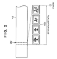
- FIG. 2 is a conceptual view showing an example of information recorded on a magnetic tape and an image to be displayed upon execution of a REC review function when different recording formats are not mixed;
- FIG. 3 is a conceptual view showing an example of information recorded on a magnetic tape and an image to be displayed upon execution of the REC review function when the recording formats are not changed during REC review although the different recording formats are mixed;
- FIG. 4 is a view for explaining problems that may be posed when the recording formats are changed during REC review
- FIG. 5 is a view for explaining the REC review operation and display image of the digital video camera according to the first embodiment of the present invention
- FIG. 6 is a view for explaining the REC review operation and display image of the digital video camera according to the second embodiment of the present invention.
- FIG. 7 is a view for explaining the REC review operation and display image of the digital video camera according to the third embodiment of the present invention.
- FIG. 1 is a block diagram showing an example of the arrangement of a digital video camera (DVC) as an embodiment of a playback apparatus according to the present invention.
- DVC digital video camera
- the video camera shown in FIG. 1 can record and play back an SD image signal in the DV format and an HD image signal in the HDV format.
- the user can arbitrarily switch between the DV format and the HDV format upon recording by operating an operation unit 712 .
- an image sensing unit 701 is used to photograph an object, and outputs an SD or HD image signal.
- An input/output signal processor 702 applies known signal processing to the image signal output from the image sensing unit 701 , and outputs the image signal that has undergone the signal processing to a memory I/F 707 . Furthermore, the input/output signal processor 702 converts an image signal read out via the memory I/F 707 to a format suited to output in a playback mode.
- An MPEG processor 703 encodes and decodes an HD image signal by MPEG.
- a DV processor 704 encodes and decodes an SD image signal according to an intra-frame encoding method specified in the DV format.
- a mux/demux unit 705 appends additional information including a sync signal and other data to image data output via the memory I/F 707 in a recording mode. Furthermore, the mux/demux unit 705 detects image data, additional information, and the like from data to be played back, and outputs them to the memory I/F 707 or a controller 711 in the playback mode.
- a memory 706 is a large-capacity recording medium such as an SDRAM or the like.
- the memory I/F 707 controls read and write accesses of data between respective units and the memory 706 .
- a recording/playback unit 708 records data in the DV or HDV format on a magnetic tape 709 . Furthermore, the recording/playback unit 708 plays back data in the DV or HDV format recorded on the magnetic tape 709 .
- the controller 711 is used to control the processing of the digital video camera, and comprises, e.g., a CPU, ROM, and RAM.
- the ROM stores a program required to execute processing of this embodiment.
- the CPU executes the program stored in the ROM.
- the RAM serves as a work area used when the CPU executes the program stored in the ROM, and temporarily stores data.
- the operation unit 712 has various switches such as a recording/playback trigger switch, REC review instruction switch, and the like.
- a tape transport mechanism 713 has a capstan motor, capstans, and the like, and transports the magnetic tape 709 .
- a display controller 714 generates data to be displayed on a display screen of a display unit 715 and outputs it to the display unit 715 in accordance with an image signal from the memory I/F 707 and an instruction from the controller 711 .
- the display unit 715 is, for example, a liquid crystal display device.
- An output unit 716 externally outputs playback image data.
- image sensing unit 701 input/output signal processor 702 , MPEG processor 703 , DV processor 704 , mux/demux unit 705 , recording/playback unit 708 , controller 711 , tape transport mechanism 713 , and display controller 714 are connected to a control bus 710 . These units can communicate with each other via the control bus 710 .
- the memory 706 is commonly used by the respective units, and read and write accesses to the memory 706 are arbitrated by the memory I/F 707 .
- the user can select one of recording formats, i.e., the DV and HDV formats by operating the operation unit 712 upon recording.
- the controller 711 controls the memory I/F 707 in accordance with the recording format of user's choice to change address mapping on the memory 706 to a format suited to the recording format of user's choice.
- the controller 711 controls the image sensing unit 701 to output an SD image. Also, the controller 711 controls the DV processor 704 to encode the sensed image. On the other hand, when the user selects the HDV format, the controller 711 controls the image sensing unit 701 to output an HD image. Also, the controller 711 controls the MPEG processor 703 to encode the photographed image.
- an image signal recorded in the DV format and that recorded in the HDV format can be mixed and recorded.
- the mux/demux unit 705 discriminates based on identification information in the readout signal if that signal was recorded in the DV or HDV format.
- the mux/demux unit 705 notifies the controller 711 of the discriminated recording format.
- the controller 711 changes address mapping on the memory 706 according to the recording format notified by the mux/demux unit 705 .
- the controller 711 controls one of the MPEG processor 703 and DV processor 704 to decode the image signal according to the notified recording format.
- the controller 711 controls the display controller 714 to read out the decoded image signal via the memory I/F 707 , and to display it on the display unit 715 .
- the controller 711 controls the tape transport mechanism 713 to continue transporting of the magnetic tape 709 intact. Furthermore, the controller 711 controls the mux/demux unit 705 to stop a data write access to the memory I/F 707 . The controller 711 changes address mapping on the memory 706 via the memory I/F 707 . Upon completion of change of address mapping, the controller 711 controls the mux/demux unit 705 to restart the data write access to the memory I/F 707 .
- the controller 711 controls the tape transport mechanism 713 to execute REC review processing as follows.
- FIG. 2 is a conceptual view showing information recorded on the magnetic tape 709 and an image to be displayed upon execution of the REC review function.
- FIG. 2 shows a case wherein data is recorded in only one recording format of the DV format and HDV format.
- the user when the user newly sets a magnetic tape 709 on which an image signal has already been recorded in the video camera, and is about to start recording, he or she may want to confirm if the recording start position poses no problem.
- the user can confirm if the current tape position poses no problem as the recording start position by using the REC review function at the current tape position.
- the controller 711 controls the tape transport mechanism 713 to rewind the magnetic tape 709 from a tape stop position (full inverted-triangle mark in FIG. 2 ) 102 shown in FIG. 2 by an amount corresponding to a predetermined time period. After that, the controller 711 controls the recording/playback unit 708 to play back an image signal recorded on the magnetic tape 709 for the predetermined time period (N seconds). The controller 711 then controls the display controller 714 to display a playback image 103 based on the played-back image signal on the display unit 715 . After that, when playback of the image signal to the tape stop position 102 ends, a standby state (recording paused state) is set.
- the user confirms the recorded contents of the magnetic tape 709 by viewing the playback image 103 displayed on the display unit 715 and can determine if no problem is posed if he or she starts photography from the current position. If no problem is posed, the user inputs a photography start instruction to the digital video camera in the standby state, thus starting photography and recording.
- the user upon starting joint recording from a scene recorded at the tape stop position 102 of the magnetic tape 709 , the user confirms the recorded contents of the magnetic tape 709 using the aforementioned REC review function. Then, the user can determine if he or she can start recording from the current position of the magnetic tape 709 . Furthermore, by using the REC review function, the user can determine whether or not the magnetic tape 709 currently set in the digital video camera can be used in recording.
- FIG. 3 is a conceptual view showing an example of information recorded on the magnetic tape 709 and an image to be displayed upon execution of the REC review function.
- FIG. 3 shows a case wherein an image recorded in the DV format and that recorded in the HDV format are mixed on the magnetic tape 709 .
- a region 202 (SD in FIG. 3 ) recorded in the DV format and a region 203 (HD in FIG. 3 ) recorded in the HDV format are mixed on the magnetic tape 709 .
- a tape stop position 205 (full inverted-triangle mark in FIG. 3 ) is located within the region (DV format region) 202 recorded in the DV format.
- the controller 711 controls the tape transport mechanism 713 to rewind the magnetic tape 709 from the tape stop position 205 for a predetermined time period (N seconds).
- the controller 711 controls the recording/playback unit 708 to play back an image signal recorded in the DV format for the predetermined time period (N seconds).
- the controller 711 then controls the display controller 714 to display a playback image 207 based on the played-back image signal on the display unit 715 .
- a tape stop position 206 (open inverted-triangle mark in FIG. 3 ) is located within the region (HDV format region) 203 recorded in the HDV format.
- the controller 711 controls the tape transport mechanism 713 to rewind the magnetic tape 709 from the tape stop position 205 for a predetermined time period.
- the controller 711 controls the recording/playback unit 708 to play back an image signal recorded in the HDV format for the predetermined time period (N seconds).
- the controller 711 then controls the display controller 714 to display a playback image 208 based on the played-back image signal on the display unit 715 .
- the controller 711 controls the recording/playback unit 708 to play back and display image signals recorded in both the DV format region 202 and HDV format region 203 from the magnetic tape 709 during single execution of the REC review function.
- FIG. 4 is a conceptual view showing an example of information recorded on the magnetic tape 709 and an image to be displayed upon execution of the REC review function.
- FIG. 4 shows a case wherein a DV format region 302 (SD in FIG. 4 ) and an HDV format region 303 (HD in FIG. 4 ) are mixed on the magnetic tape 709 .
- a tape stop position 306 is located near a boundary 305 with the DV format region 302 within the HDV format region 303 .
- a blue-backed screen 310 may be displayed in place of an image on the display unit 715 , as shown in FIG. 4 .
- the execution instruction of the REC review function is input at the tape stop position 306 (full inverted-triangle mark in FIG. 4 ).
- the magnetic tape 709 is rewound from the tape stop position 306 for N seconds, and playback is started. Since the playback start position is located within the DV format region 302 , a playback image 308 by the internal processing corresponding to the DV format is displayed on the display unit 715 .
- the recording format of the magnetic tape 709 is switched from the DV format to the HDV format from the boundary 305 , the internal processing must also be switched in correspondence with the HDV format.
- the blue-backed screen 310 is displayed on the display unit 715 during switching of the internal processing. If switching is completed within the predetermined time period (N seconds) after the beginning of playback by the REC review function, an image signal 309 based on the image signal recorded in the HDV format can be displayed on the display unit 715 after display of the blue-backed screen 310 .
- a blue-backed screen is also displayed.
- a tape stop position (open inverted triangle mark in FIG. 4 ) 307 is located within an unrecorded region 304 of an image signal
- a blue-backed screen 311 is displayed after an end position 312 of the HDV format region 303 .
- blue-backed screen 310 due to the beginning of a region in the different recording format (blue-backed screen 310 ) or due to the beginning of an unrecorded part of an image signal (blue-backed screen 311 ).
- the user may mistake the blue-backed screen 310 due to the beginning of the region in the different recording format for the blue-backed screen 311 due to the beginning of the “unrecorded part of an image signal”.
- the user may overwrite an image signal on the already recorded region (e.g., the HDV format region 303 in FIG. 3 ).
- a zone in which playback is made by the REC review function (to be referred to as a REC review zone hereinafter) includes a plurality of different format regions
- the REC review operation is controlled as follows.
- the controller 711 changes a playback time period of an image signal by the REC review function.
- the controller 711 dynamically varies the REC review zone. More specifically, the controller 711 changes the playback time period so that the REC review function ends with display of an image in place of the blue-backed screen.
- the user can clearly identify the blue-backed screens 310 and 311 , and can be avoided from overwriting data on the already recorded region while mistaking for an unrecorded region.
- FIG. 5 is a conceptual view showing an example of information recorded on the magnetic tape 709 and an image to be displayed upon execution of the REC review function.
- FIG. 5 shows a case wherein a DV format region 402 (SD in FIG. 5 ), an HDV format region 403 (HD in FIG. 5 ), and an unrecorded region 404 of an image signal are mixed on the magnetic tape 709 .
- FIG. 5 shows an example of a method of solving the problem described using FIG. 4 .
- a predetermined time period for playing back an image signal by executing the REC review function is set to be N seconds.
- the duration of the REC review zone is extended to (N+M) seconds.
- the controller 711 controls the tape transport mechanism 713 to rewind the magnetic tape 709 from the tape stop position 406 for N seconds.
- the controller 711 then controls the recording/playback unit 708 to start playback. Since the playback start position is located within the DV format region 402 , the controller 711 controls the recording/playback unit 708 and DV processor 704 to display a playback image 407 based on the image signal recorded in the DV format on the display unit 715 .
- the controller 711 detects the beginning of the HDV format region 403 .
- the controller 711 changes the playback time period by the REC review function from N seconds to (N+M) seconds. That is, the controller 711 extends the REC review zone.
- the value M is set so that M seconds become longer than a time period required to switch from the DV format to the HDV format.
- the controller 711 starts switching of the internal processing, and controls the display controller 714 to start display of a blue-backed screen 408 on the display unit 715 .
- the controller 711 controls to start display of a playback image 409 based on the image signal in the HDV format region 403 and to stop the magnetic tape 709 after an elapse of (N+M) seconds from the beginning of playback.
- N+M elapse of (N+M) seconds
- the playback time period of an image signal by the REC review function is extended according to the recording format of an image recorded on the magnetic tape 709 . Even when the recording format is changed during playback of an image signal by the REC review function, the playback image 409 based on the signal recorded in the recording format after change can be displayed on the display unit 715 after the blue-backed screen 408 is displayed.
- the boundaries recorded on the magnetic tape 709 can be displayed on the display unit 715 during REC review.
- the REC review of the recorded region never ends with display of a blue-backed screen. For this reason, the user can determine whether a blue-backed screen is displayed owing to switching of the internal processing of the apparatus or owing to an unrecorded part of an image signal upon playing back an image signal by executing the REC review function. Therefore, the user can be avoided as much as possible from mistaking the blue-backed screen 408 displayed due to a change in recording format for a blue-backed screen displayed in correspondence with the unrecorded region 404 of an image signal on the magnetic tape 709 .
- the user can be prevented as much as possible from issuing a recording instruction of an image signal on an unintended recording region, and can be prevented as much as possible from overwriting a new image signal on the recorded region of an image signal by mistake.
- the magnetic tape 709 has been exemplified as a recording medium that records an image signal.
- the recording medium that records an image signal need not always be the magnetic tape 709 .
- any other recording media such as a flexible disk and the like may be used as long as they perform recording.
- This embodiment is substantially the same as the aforementioned first embodiment, except for some processes in the method of playing back an image signal upon execution of the REC review function. Therefore, in the following description, the same reference numerals as those in FIGS. 1 to 5 denote the same parts as in the first embodiment, and a detailed description thereof will be omitted.
- FIG. 6 is a conceptual view showing an example of information recorded on the magnetic tape 709 and an image displayed upon execution of the REC review function.
- a tape stop position 406 (full inverted-triangle mark in FIG. 6 ) is located near a boundary 405 between a DV format region 402 and an HDV format region 403 .
- a playback image 407 based on the image signal recorded in the DV format is displayed on the display unit 715 , and the position of the magnetic tape 709 moves into the HDV format region 403 via the boundary 405 between the regions 402 and 403 of the different recording formats.
- the controller 711 controls the recording/playback unit 708 to continue the playback operation of the image signal by the REC review function.
- the controller 711 controls to continue the playback operation until the camera is ready to play back an image recorded in the other format. Then, the playback operation of the image signal by the REC review function ends when an image recorded in the other format can be played back, thus setting the standby state.
- the playback operation of the image signal by the REC review function is continued until the digital video camera shifts from a playback state of an image recorded in the DV format to a state wherein it is ready to play back an image recorded in the HDV format.
- the controller 711 executes the following processing during transition to the state the camera is ready to play back an image recorded in the HDV format by the REC review function, i.e., during switching of the internal processing of the digital video camera to support the HDV format.
- the controller 711 controls to display a blue-backed screen 408 on the display unit 715 , and to continuously execute the REC review function.
- the controller 711 enables playback of an image signal by the continuously executed REC review function. In this way, a playback image 509 based on an image signal recorded in the HDV format can be displayed on the display unit 715 by the REC review function.
- the playback time period of an image signal by the REC review function can be changed in accordance with a time period required until the camera is ready to play back an image recorded in the HDV format.
- This embodiment is substantially the same as the aforementioned first and second embodiments, except for an image displayed during switching (transition period) when switching of the internal processing occurs during execution of the REC review function. Therefore, in the following description, the same reference numerals as those in FIGS. 1 to 6 denote the same parts as in the first and second embodiments, and a detailed description thereof will be omitted.
- FIG. 7 is a conceptual view showing an example of an image displayed upon execution of the REC review function.
- the digital video camera begins to switch the internal processing to a state wherein it can display a playback image 509 based on an image signal recorded in the HDV format.
- a blue-backed screen is displayed on the display unit 715 during this switching processing (transition period).
- an image that allows the user to recognize switching of the internal processing e.g., a blue-backed screen 608 with text “SD HD” is displayed on the display unit 715 .
- the user can determine at a glance whether a blue-backed screen is displayed due to the switching processing of the internal processing or due to an unrecorded part of an image signal.
- the contents attached to the blue-backed screen are not limited to those shown in FIG. 7 .
- Text, a figure, or a symbol that allows the user to recognize mode transition, or a combination of them may be used.
- a different background color may be used.
- the recording format at the beginning of playback by the REC review function matches the internal processing method of the digital video camera.
- a case wherein they do not match may occur.
- the playback time period (N seconds) of the REC review function is normally longer than a time period required to switch the internal processing, the REC review function does not end with display of the blue-backed screen. Therefore, the playback time period of the REC review function need not be extended to cope with switching of the internal processing at the beginning of playback, and it need only be extended at the time of detection of a change in recording format within the REC review zone later.
- blue-backed screen display described in the third embodiment can be made even during switching of the internal processing at the beginning of playback.
- the tape position upon completion of the REC review function is different from that upon reception of the execution instruction of the REC review function. For this reason, when the playback time period is extended, after playback by the REC review function ends, the magnetic tape may be rewound to the tape position upon reception of the execution instruction of the REC review function to set the standby state.
- Such embodiment can be easily implemented when the tape position upon reception of the execution instruction of the REC review function is stored, and the controller 711 controls the tape transport mechanism 713 to rewind the magnetic tape to the stored position.
- the aforementioned embodiments can be implemented by software using a computer (or a CPU, MPU, or the like) of a system or an apparatus.
- a computer program itself supplied to the computer to implement the aforementioned embodiments by the computer also implements the present invention. That is, the computer program itself required to implement the functions of the aforementioned embodiments is one constituent element of the present invention.
- the form of the computer program required to implement the aforementioned embodiments is not particularly limited as long as the computer program is readable by the computer.
- an object code, a program to be executed by an interpreter, script data to be supplied to an OS, and the like may be used, but the present invention is not limited to them.
- the computer program required to implement the aforementioned embodiments is supplied to the computer via a storage medium or a wired/wireless communication.
- a storage medium used to supply the program for example, magnetic storage media such as a flexible disk, hard disk, magnetic tape, and the like, optical/magneto-optical storage media such as an MO, CD, DVD, and the like, a nonvolatile semiconductor memory, and the like may be used.
- a method utilizing a server on a computer network is available.
- a data file which can be the computer program that forms the present invention is stored in the server.
- the program file a file having an executable format, source codes, and the like may be used.
- the program file is supplied to a client computer which accesses this server by downloading the program file.
- the program file may be divided into a plurality of segment files, which may be distributed and allocated in different servers.
- the server which provides the program file required to implement the aforementioned embodiments to the client computer is one of the present invention.
- a storage medium that stores the encrypted computer program required to implement the aforementioned embodiments may be delivered to the user, and the user who has cleared a predetermined condition may be allowed to receive key information used to decrypt the encrypted program and to install the decrypted program in his or her computer.
- the key information can be supplied by downloading it from a homepage via, e.g., the Internet.
- the computer program required to implement the aforementioned embodiments may utilize the functions of an OS which is already running on the computer.
- some functions of the computer program required to implement the aforementioned embodiments may be configured by firmware in an expansion board or the like connected to the computer, or the computer program may be executed by a CPU of the expansion board or the like.
Landscapes
- Engineering & Computer Science (AREA)
- Multimedia (AREA)
- Signal Processing (AREA)
- Signal Processing For Digital Recording And Reproducing (AREA)
- Television Signal Processing For Recording (AREA)
Applications Claiming Priority (2)
| Application Number | Priority Date | Filing Date | Title |
|---|---|---|---|
| JP2005212744A JP2007036358A (ja) | 2005-07-22 | 2005-07-22 | 再生装置、再生方法、及びコンピュータプログラム |
| JP2005-212744 | 2005-07-22 |
Publications (2)
| Publication Number | Publication Date |
|---|---|
| US20070019928A1 US20070019928A1 (en) | 2007-01-25 |
| US8041191B2 true US8041191B2 (en) | 2011-10-18 |
Family
ID=37656915
Family Applications (1)
| Application Number | Title | Priority Date | Filing Date |
|---|---|---|---|
| US11/479,478 Expired - Fee Related US8041191B2 (en) | 2005-07-22 | 2006-06-30 | Image playback apparatus and playback method |
Country Status (3)
| Country | Link |
|---|---|
| US (1) | US8041191B2 (zh) |
| JP (1) | JP2007036358A (zh) |
| CN (1) | CN100530404C (zh) |
Families Citing this family (2)
| Publication number | Priority date | Publication date | Assignee | Title |
|---|---|---|---|---|
| JP4788522B2 (ja) * | 2006-08-10 | 2011-10-05 | ソニー株式会社 | データ処理装置及びデータ処理方法、並びにコンピュータ・プログラム |
| US9153246B1 (en) | 2014-09-25 | 2015-10-06 | International Business Machines Corporation | Magnetic tape rewind overwrite data protection |
Citations (3)
| Publication number | Priority date | Publication date | Assignee | Title |
|---|---|---|---|---|
| JP2001275077A (ja) | 2000-03-27 | 2001-10-05 | Sony Corp | 磁気テープ記録装置および方法、磁気テープ再生装置および方法、磁気テープのフォーマット、並びに記録媒体 |
| US20040022519A1 (en) * | 2002-08-05 | 2004-02-05 | Samsung Electronics Co., Ltd. | Method of and apparatus for recording data in various recording formats on an optical storage medium, method of and apparatus for reproducing the data, and an optical storage medium on which the data is recorded |
| US20060045493A1 (en) * | 2004-08-27 | 2006-03-02 | Sony Corporation | Reproducing apparatus and reproducing method |
Family Cites Families (2)
| Publication number | Priority date | Publication date | Assignee | Title |
|---|---|---|---|---|
| JP3277713B2 (ja) * | 1994-08-31 | 2002-04-22 | ソニー株式会社 | ディジタルビデオ信号の記録装置、記録再生装置及び再生装置 |
| JP2004242172A (ja) * | 2003-02-07 | 2004-08-26 | Canon Inc | 再生装置 |
-
2005
- 2005-07-22 JP JP2005212744A patent/JP2007036358A/ja active Pending
-
2006
- 2006-06-30 US US11/479,478 patent/US8041191B2/en not_active Expired - Fee Related
- 2006-07-21 CN CNB2006101035499A patent/CN100530404C/zh not_active Expired - Fee Related
Patent Citations (3)
| Publication number | Priority date | Publication date | Assignee | Title |
|---|---|---|---|---|
| JP2001275077A (ja) | 2000-03-27 | 2001-10-05 | Sony Corp | 磁気テープ記録装置および方法、磁気テープ再生装置および方法、磁気テープのフォーマット、並びに記録媒体 |
| US20040022519A1 (en) * | 2002-08-05 | 2004-02-05 | Samsung Electronics Co., Ltd. | Method of and apparatus for recording data in various recording formats on an optical storage medium, method of and apparatus for reproducing the data, and an optical storage medium on which the data is recorded |
| US20060045493A1 (en) * | 2004-08-27 | 2006-03-02 | Sony Corporation | Reproducing apparatus and reproducing method |
Also Published As
| Publication number | Publication date |
|---|---|
| JP2007036358A (ja) | 2007-02-08 |
| US20070019928A1 (en) | 2007-01-25 |
| CN100530404C (zh) | 2009-08-19 |
| CN1901073A (zh) | 2007-01-24 |
Similar Documents
| Publication | Publication Date | Title |
|---|---|---|
| US8437623B2 (en) | Recording apparatus and method | |
| JP4051776B2 (ja) | 映像情報記録装置、及び映像情報再生装置 | |
| US8208793B2 (en) | Recording apparatus | |
| US20070183749A1 (en) | Content reproduction apparatus, content reproduction method, content reproduction system, and computer program therefor | |
| US20140133835A1 (en) | Image processing apparatus, image processing method, and program | |
| JP4323870B2 (ja) | 記録装置 | |
| US7561297B2 (en) | Display method during sensed image recording in image sensing apparatus | |
| US8041191B2 (en) | Image playback apparatus and playback method | |
| JP4865386B2 (ja) | ビデオカメラ | |
| JP2005198165A (ja) | 画像再生装置、画像再生方法、コンピュータプログラム及びコンピュータ読み取り可能な記録媒体 | |
| US7249898B2 (en) | Function control method for camera | |
| JP2006191169A (ja) | 画像記録装置、撮像装置、及び画像記録再生装置 | |
| JP4352174B2 (ja) | 再生装置、及びプログラム | |
| US8103146B2 (en) | DVD player and optical disk reproducing apparatus | |
| US7760608B2 (en) | Reproducing apparatus | |
| JP2005142674A (ja) | 画像記録装置およびその制御方法 | |
| US20070126879A1 (en) | Recording and reproducing apparatus, recording apparatus, and system including them | |
| JP4350590B2 (ja) | 記録装置、記録方法、コンピュータプログラム及び記録媒体 | |
| JP4745919B2 (ja) | 撮像装置及び撮像装置の制御方法 | |
| JP2007074433A (ja) | 撮像装置 | |
| JP4836273B2 (ja) | 映像撮像装置 | |
| JP2006059098A (ja) | 記録装置及びその制御方法 | |
| JP4336511B2 (ja) | データ転送装置、データ転送システム及びプログラム | |
| JP4603804B2 (ja) | ビデオカメラ及びその制御方法 | |
| JP5409018B2 (ja) | 撮像装置 |
Legal Events
| Date | Code | Title | Description |
|---|---|---|---|
| AS | Assignment |
Owner name: CANON KABUSHIKI KAISHA, JAPAN Free format text: ASSIGNMENT OF ASSIGNORS INTEREST;ASSIGNOR:WADA, KATSUHIRO;REEL/FRAME:018030/0723 Effective date: 20060629 |
|
| STCF | Information on status: patent grant |
Free format text: PATENTED CASE |
|
| FPAY | Fee payment |
Year of fee payment: 4 |
|
| FEPP | Fee payment procedure |
Free format text: MAINTENANCE FEE REMINDER MAILED (ORIGINAL EVENT CODE: REM.); ENTITY STATUS OF PATENT OWNER: LARGE ENTITY |
|
| LAPS | Lapse for failure to pay maintenance fees |
Free format text: PATENT EXPIRED FOR FAILURE TO PAY MAINTENANCE FEES (ORIGINAL EVENT CODE: EXP.); ENTITY STATUS OF PATENT OWNER: LARGE ENTITY |
|
| STCH | Information on status: patent discontinuation |
Free format text: PATENT EXPIRED DUE TO NONPAYMENT OF MAINTENANCE FEES UNDER 37 CFR 1.362 |
|
| FP | Expired due to failure to pay maintenance fee |
Effective date: 20191018 |