US7802425B2 - Method for controlling or regulating the air pressure in a compressed air supply device - Google Patents
Method for controlling or regulating the air pressure in a compressed air supply device Download PDFInfo
- Publication number
- US7802425B2 US7802425B2 US12/273,242 US27324208A US7802425B2 US 7802425 B2 US7802425 B2 US 7802425B2 US 27324208 A US27324208 A US 27324208A US 7802425 B2 US7802425 B2 US 7802425B2
- Authority
- US
- United States
- Prior art keywords
- pressure
- compressed air
- clutch
- value
- supply device
- Prior art date
- Legal status (The legal status is an assumption and is not a legal conclusion. Google has not performed a legal analysis and makes no representation as to the accuracy of the status listed.)
- Expired - Fee Related, expires
Links
Images
Classifications
-
- B—PERFORMING OPERATIONS; TRANSPORTING
- B60—VEHICLES IN GENERAL
- B60T—VEHICLE BRAKE CONTROL SYSTEMS OR PARTS THEREOF; BRAKE CONTROL SYSTEMS OR PARTS THEREOF, IN GENERAL; ARRANGEMENT OF BRAKING ELEMENTS ON VEHICLES IN GENERAL; PORTABLE DEVICES FOR PREVENTING UNWANTED MOVEMENT OF VEHICLES; VEHICLE MODIFICATIONS TO FACILITATE COOLING OF BRAKES
- B60T17/00—Component parts, details, or accessories of power brake systems not covered by groups B60T8/00, B60T13/00 or B60T15/00, or presenting other characteristic features
- B60T17/02—Arrangements of pumps or compressors, or control devices therefor
-
- F—MECHANICAL ENGINEERING; LIGHTING; HEATING; WEAPONS; BLASTING
- F04—POSITIVE - DISPLACEMENT MACHINES FOR LIQUIDS; PUMPS FOR LIQUIDS OR ELASTIC FLUIDS
- F04B—POSITIVE-DISPLACEMENT MACHINES FOR LIQUIDS; PUMPS
- F04B35/00—Piston pumps specially adapted for elastic fluids and characterised by the driving means to their working members, or by combination with, or adaptation to, specific driving engines or motors, not otherwise provided for
- F04B35/002—Piston pumps specially adapted for elastic fluids and characterised by the driving means to their working members, or by combination with, or adaptation to, specific driving engines or motors, not otherwise provided for driven by internal combustion engines
-
- F—MECHANICAL ENGINEERING; LIGHTING; HEATING; WEAPONS; BLASTING
- F04—POSITIVE - DISPLACEMENT MACHINES FOR LIQUIDS; PUMPS FOR LIQUIDS OR ELASTIC FLUIDS
- F04B—POSITIVE-DISPLACEMENT MACHINES FOR LIQUIDS; PUMPS
- F04B49/00—Control, e.g. of pump delivery, or pump pressure of, or safety measures for, machines, pumps, or pumping installations, not otherwise provided for, or of interest apart from, groups F04B1/00 - F04B47/00
- F04B49/02—Stopping, starting, unloading or idling control
- F04B49/022—Stopping, starting, unloading or idling control by means of pressure
Definitions
- the present invention relates to a method for controlling and/or regulating the air pressure in a compressed air supply device for a utility or commercial vehicle, with the steps: detection of at least one pressure value in the compressed air supply device and/or in vehicle components connected to the compressed air supply device, determination of a moisture value which represents the moisture content in an air filter unit belonging to the compressed air supply device, and opening of a shiftable clutch connecting a drive to a compressor, and also opening of a discharge valve of the compressed air supply device when the pressure value lies above a predetermined minimum value and the moisture value overshoots a predetermined threshold value.
- the invention relates, furthermore, to a compressed air supply device and to a utility vehicle having a compressed air supply device.
- Compressed air supply devices are of a central importance for utility vehicles.
- the brake system of a pneumatically braked utility vehicle requires compressed air, as do numerous further consumers, for example air suspensions or lift axle devices.
- the compressed air to be prepared and distributed by the compressed air supply device is delivered by a compressor which is driven, in general, by the internal combustion engine of the utility vehicle.
- the compressor is coupled to the internal combustion engine via a pneumatically shiftable clutch, the compressed air for the pneumatic activation of the clutch being extracted, in turn, from the compressed air supply device.
- An example of a device of this type is given in DE 3923882 C2.
- the operation of the compressor can be interrupted, as required, for example during the regeneration phases of the filter unit.
- a conveyance of air through the filter unit in the direction of the consumer is interrupted while a regeneration of the filter unit is taking place, wherein dry air is conducted out of the reservoirs through the filter unit in the opposite direction.
- the dry air absorbs the moisture and can then escape via a discharge valve.
- the discharge valve is also opened when the pressure prevailing in the compressed air supply device reaches a maximum value.
- Functionality as a pressure controller is thereby made available by the compressed air supply device.
- any action of the pressure controller entails compressed air losses via the discharge valve and other switching losses related to the electrical, electropneumatic and pneumatic valves.
- the object on which the invention is based is to make available a method having an improved energy balance with regard to the pressure controller function.
- the invention builds on the generic method in that the clutch is opened and the discharge valve remains closed when it is indicated that the clutch can be engaged, the pressure value reaches a predetermined switch-off pressure and the moisture value lies below the predetermined threshold value.
- the clutch can assume the pressure controller function independently of the discharge valve.
- the clutch is opened with minimal compressed air consumption, whereas the discharge valve remains closed in order to avoid considerably higher compressed air losses.
- the discharge valve has to be opened only when regeneration is actually necessary, as can be detected by the overshooting of a moisture threshold value.
- the moisture value In the case of calculation of the moisture value, there is provision for the moisture value to be calculated, taking into account the conveyed air volume and the efficiency of the air filter unit.
- the conveyed air volume can be calculated from the characteristic data of the compressor and from the rotational speed of the compressor.
- the moisture content is then obtained by summing or integrating the calculated moisture contributions over time.
- the temperature of the surroundings is taken into account in the calculation of the moisture value.
- Warm air as a rule, stores more water than cold air. If a temperature-dependent correcting factor is defined and if the correcting factors determined on the basis of this definition are adopted in the summation or integration for determining the moisture content of the air filter unit, then the average time between the regeneration phases can be further prolonged, particularly in winter.
- the clutch to remain closed and for the discharge valve to be opened when the shiftability of the clutch is not afforded on account of a defect, the pressure value reaches a predetermined switch-off pressure and the moisture value lies below the predetermined threshold value.
- Conventional pressure control via the discharge valve thus offers a substitute function for the primarily employed pressure control via the shiftable clutch.
- the pressure control function can thus take place by means of the electronic control on the basis of the determined values, preferably taking into account other parameters relating to the compressed air supply system or, in general, to the vehicle.
- the electronic control is integrated into a compressed air preparation plant.
- This can be implemented, in practice, in that the conventional electronic control of the compressed air preparation plant is extended to include the functionality of clutch activation.
- the electronic control communicates via an interface with a control integrated into a compressed air preparation plant.
- the conventional electronic control of the compressed air preparation plant can remain largely unchanged, and the shift functionality for the clutch can be available externally.
- the at least one pressure value may be detected by a pressure switch which, when the switch-off pressure is reached, generates an electrical signal for opening the clutch.
- a pressure switch may assume sole management by pressure control or act redundantly to pressure control by the electronic control.
- the electrical signal generated by the pressure switch may be supplied directly to an electrically switchable valve for the pneumatic activation of the clutch or to the electronic control, so that the latter makes available the electrical signal for the pilot control of the pneumatic valve.
- the invention relates, furthermore, to a compressed air supply device for carrying out a method according to the invention and to a utility vehicle having a compressed air supply device according to the invention.
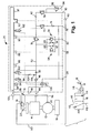
- FIG. 1 shows a diagrammatic illustration of a compressed air supply device according to the invention
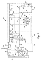
- FIG. 2 shows a diagrammatic illustration of a compressed air supply device according to the invention
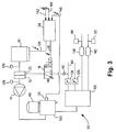
- FIG. 3 shows a diagrammatic illustration of a compressed air supply device according to the invention.
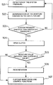
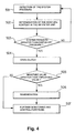
- FIG. 4 shows a flow chart for explaining a method according to the invention.
- FIG. 1 shows a diagrammatic illustration of a compressed air supply device according to the invention.
- a compressed air preparation plant 26 is illustrated. By means of this, compressed air supplied is filtered and is distributed to various compressed air consumers.
- An inlet connection 44 is provided, which is connected to a compressor 14 provided outside the compressed air preparation plant 26 .
- An extraneous filing connection 46 is arranged parallel to the inlet connection 44 .
- the compressed air supplied to one of the inlets 44 , 46 is supplied to a filter unit 48 and from there, via a nonreturn valve 50 , to a main supply line 52 .
- Arranged in parallel on the main supply line 52 are two overflow valves 54 , 56 , via which connections 58 , 60 for the service brake circuits of the utility vehicle are supplied with compressed air.
- a throttle 62 , 64 and a nonreturn valve 66 , 68 are arranged in each case parallel to the overflow valves, according to the present embodiment a flow, parallel to the flow through the overflow valves 54 , 56 , from the main supply line 52 to the connections 58 , 60 of the service brake circuits being made possible.
- a flow parallel to the flow through the overflow valves 54 , 56 , from the main supply line 52 to the connections 58 , 60 of the service brake circuits being made possible.
- a pressure limiter 70 is provided in the main supply line 52 .
- Two further lines branch off in parallel on the pressure-limited side of the pressure limiter 70 , a connection 76 for the parking brake and the trailer brake system being supplied by means of one line via an overflow valve 72 and a nonreturn valve 74 .
- the other line via a nonreturn valve 42 and an overflow valve 78 , feeds a connection 80 which is provided for actuating the compressor clutch 12 .
- the overflow valve 78 is followed in a branching-off line by a further overflow valve 82 via which a further secondary consumer connection 84 is supplied.
- a plurality of pressure sensors 86 , 88 , 90 , 92 are connected to the electronic control 32 , the pressure sensor 88 measuring the pressure at the service brake connection 58 , the pressure sensor 90 measuring the pressure at the service brake connection 60 and the pressure sensor 62 measuring the pressure directly downstream of the overflow valve 72 for the connection 76 of the parking brake and trailer. Furthermore, a temperature sensor 94 and a heating 96 are connected to the electronic control 32 . Moreover, three solenoid valves 98 , 100 , 102 are connected to the electronic control 32 : the pressure controller solenoid valve 98 , the regeneration solenoid valve 100 and a solenoid valve 102 for the additional pressure control of the overflow valve 72 .
- the solenoid valves 78 , 100 , 102 are designed as 3/2-way valves and are all closed in the currentless state. In the closed state, the pressure of the main supply line 52 is present at the inputs of the solenoid valves 98 , 100 , 102 . To initiate a regeneration operation, it is necessary to apply current to the regeneration solenoid valve 100 and the pressure controller solenoid valve 98 and thus transfer them into their state not illustrated.
- a 3/2-way valve 18 is arranged, which in the present case is designed as an electrically pilot-controlled pneumatic valve, as is also illustrated separately.
- the pneumatic valve 18 has an inlet connection 110 to which a line 112 leading to the clutch connection 80 is connected.
- a nonreturn valve 40 is arranged, which permits a flow from the clutch connection 80 to the valve 18 and prevents a reverse flow.
- the valve 18 has an outlet connection which is coupled to a shift input 20 of the clutch 12 via a line 116 .
- Via an electrical input 118 for the purpose of supplying a signal 16 the valve is connected to the electronic control 32 of the compressed air preparation plant 26 and to a ground which is picked off at a central plug 120 .
- the compressed air supply device operates as follows in terms of the shiftable clutch 12 .
- the electronic control 32 sends an output signal 16 to the electrically pilot-controlled pneumatic valve 18 .
- the valve 18 opens, and a connection is thereby made between the clutch connection 80 of the compressed air preparation plant 26 and the shift input 20 of the clutch 12 .
- the clutch 12 is opened.
- the pressure controller solenoid valve 98 and the regeneration solenoid valve 100 are changed over, so that the discharge valve 106 opens and dry air can flow out of the consumer-side reservoirs in the opposite direction through the filter unit 48 , the discharge valve 106 and the discharge 108 into the open. If regeneration is not required, however, the solenoid valves 98 , 100 remain in the closed state. The opening of the clutch 12 then alone assumes the pressure controller function. To close the clutch 12 , the application of current to the electric input 118 is discontinued again, so that the shift input 20 is vented. A short switching time is ensured by means of the nonreturn valves 40 , 42 .
- the nonreturn valve 42 prevents a backflow of compressed air out of the line 112 in the direction of the branches of the service brake connections 58 , 60 and the connection for the parking brake and the trailer.
- the nonreturn valve 40 additionally prevents a backflow out of the line 112 to the secondary consumer connection 84 .
- one of the nonreturn valves 40 , 42 may be sufficient.
- the nonreturn valves 40 , 42 thus ensure that a certain pressure level can always be maintained in the intact line 112 , so that, during the changeover of the valve 18 , a rapid pressure build-up at the shift input 20 of the compressor 14 is ensured.
- An additional reservoir in the region of the line 112 by means of which reservoir the maintaining of such a pressure level could likewise be ensured, is therefore unnecessary.
- FIG. 2 shows a diagrammatic illustration of a compressed air supply device according to the invention.
- Many properties of the embodiment according to FIG. 2 are identical to the embodiment according to FIG. 1 , for example also the preferred arrangement of the electrically pilot-controlled pneumatic valve 18 in the region of the air inlet of the compressor 14 , even though this is not illustrated here.
- an external control 36 is provided, in addition to the electronic control 34 , in the compressed air preparation plant 28 .
- the external control 36 is suitable for communicating with the internal control 34 via an interface 122 which is preferably made available by the central plug 120 .
- An interface 124 with other vehicle components is likewise provided, for example with a vehicle management computer via a CAN bus.
- the interfaces 122 , 124 may be combined in structural terms. Furthermore, it is shown in FIG. 2 that a rotational speed sensor 126 may be arranged on the input side of the clutch 12 and a further rotational speed sensor 128 may be arranged on the output side of the clutch 12 . Moreover, a temperature sensor 130 is provided on the compressor 14 . The signals from the sensors 126 , 128 , 130 are delivered to the external control 36 and are taken into account by the latter with regard to the activation of the valve, or are evaluated in another way, for example with regard to function monitoring, and/or are transferred in original or processed form via the interfaces 122 , 124 .
- the useful determination of the rotational speeds and of the temperature may also be provided in connection with the embodiment according to FIG. 1 , even though this is not illustrated here.
- the corresponding data are then delivered to the internal control 32 of the compressed air preparation plant 26 .
- FIG. 3 shows a diagrammatic illustration of a compressed air supply device according to the invention.
- the compressed air supply device illustrated here is illustrated in the form of a plurality of distributed individual subassemblies.
- a pressure controller 130 with an attached filter unit 48 a multiple-circuit protection valve 132 , pressure limiters 134 , 136 and an electronic control 38 are illustrated.
- the components may in reality be distributed in the way described. However, the distributed illustration may also be understood in the sense of a functional division, the pressure regulator, multiple circuit protection valve, pressure limiters and/or electronic control in reality being implemented in integrated forms, for example as illustrated in connection with FIGS. 1 and 2 .
- a compressor 14 is coupled to an internal combustion engine 10 via a shiftable clutch 12 .
- the compressor 14 delivers compressed air to the pressure controller 130 , from where the compressed air is transferred to the multiple-circuit protection valve 132 .
- the multiple-circuit protection valve 132 distributes the compressed air to the reservoirs 138 , 140 and other connections, one of which is illustrated as a connection provided with a pressure limiter 136 .
- a further connection is the clutch connection 80 , likewise supplied via a pressure limiter 134 .
- Compressed air is delivered to the electrically pilot-controlled pneumatic valve 18 from the clutch connection 80 via the nonreturn valve 40 ensuring the switching times.
- the activation of the valve 18 takes place by means of the electronic control 38 which likewise communicates with the internal combustion engine or with an engine control via the interface 124 .
- the electronic control 38 has a plurality of inputs 142 , 144 , 146 .
- the inputs 142 , 144 symbolize the possibility of supplying the control 38 with temperature, pressure and/or rotational speed information, for example measured by the pressure sensors 88 , 90 of the service brake circuits and/or by the rotational speed sensors 126 , 128 on the input side and the output side of the clutch 12 .
- a pressure switch 24 is provided on the pressure controller 130 . This is connected to the input 146 of the electronic control 38 .
- a pressure-dependent electrical signal can therefore be supplied to the electronic control 38 .
- the compressed air supply device operates as follows. On the basis of the information made available via the inputs 142 , 144 , 146 and the interface 124 , the electronic control 38 can deliver an electrical signal 16 to the valve 18 , so that the latter changes over and opens the clutch 12 by virtue of the ventilation of the shift input 20 .
- the decision to output the signal 16 may then be made on the basis that pressures, temperatures or rotational speeds measured by sensors make it necessary to open the clutch 12 . In parallel with this, however, the opening of the clutch may also take place on the basis of the signal output by the pressure switch 24 . If components of the embodiment illustrated in FIG.
- FIG. 4 shows a flow chart for explaining a method according to the invention.
- the system pressure is detected, for example in the region of the service brake circuits.
- the moisture content in the air filter unit is determined, either by measurement or by calculation on the basis of the air volume conveyed by the compressor, the compressor rotational speed and the efficiency of the air filter unit.
- step S 03 it is determined whether the system pressure is higher than a predetermined switch-off pressure. If this is so, in step S 04 the clutch is opened. In the opposite case, no opening of the clutch takes place, and the sequence returns to step S 01 .
- step S 05 After the opening of the clutch in step S 04 , in step S 05 a check is made as to whether the moisture value is higher than a predetermined threshold value. If this is so, in step S 06 regeneration is initiated. If the moisture value is not higher than the threshold value, further monitoring and control functions may take place according to step S 07 , just as they can after regeneration according to step S 06 .
- the flow chart according to FIG. 4 illustrates only a partial aspect of the monitoring in terms of the system pressure and the moisture content. For example, a check as to whether the moisture value is higher than the threshold value is also carried out irrespective of whether the switch-off pressure is present. Regeneration is also carried out at lower pressures if the system pressure is higher than the minimum pressure.
Landscapes
- Engineering & Computer Science (AREA)
- Mechanical Engineering (AREA)
- General Engineering & Computer Science (AREA)
- Chemical & Material Sciences (AREA)
- Combustion & Propulsion (AREA)
- Transportation (AREA)
- Hydraulic Clutches, Magnetic Clutches, Fluid Clutches, And Fluid Joints (AREA)
- Valves And Accessory Devices For Braking Systems (AREA)
- Control Of Positive-Displacement Pumps (AREA)
Applications Claiming Priority (4)
| Application Number | Priority Date | Filing Date | Title |
|---|---|---|---|
| DE102006023681A DE102006023681B4 (de) | 2006-05-19 | 2006-05-19 | Verfahren zum Steuern beziehungsweise Regeln des Luftdrucks in einer Druckluftversorgungseinrichtung |
| DE102006023681 | 2006-05-19 | ||
| DE102006023681.5 | 2006-05-19 | ||
| PCT/EP2007/004422 WO2007134798A1 (de) | 2006-05-19 | 2007-05-16 | Verfahren zum steuern beziehungsweise regeln des luftdrucks in einer druckluftversorgungseinrichtung |
Related Parent Applications (1)
| Application Number | Title | Priority Date | Filing Date |
|---|---|---|---|
| PCT/EP2007/004422 Continuation WO2007134798A1 (de) | 2006-05-19 | 2007-05-16 | Verfahren zum steuern beziehungsweise regeln des luftdrucks in einer druckluftversorgungseinrichtung |
Publications (2)
| Publication Number | Publication Date |
|---|---|
| US20090133394A1 US20090133394A1 (en) | 2009-05-28 |
| US7802425B2 true US7802425B2 (en) | 2010-09-28 |
Family
ID=38328202
Family Applications (1)
| Application Number | Title | Priority Date | Filing Date |
|---|---|---|---|
| US12/273,242 Expired - Fee Related US7802425B2 (en) | 2006-05-19 | 2008-11-18 | Method for controlling or regulating the air pressure in a compressed air supply device |
Country Status (6)
| Country | Link |
|---|---|
| US (1) | US7802425B2 (https=) |
| EP (1) | EP2024214B1 (https=) |
| JP (1) | JP5254215B2 (https=) |
| CA (1) | CA2652646C (https=) |
| DE (1) | DE102006023681B4 (https=) |
| WO (1) | WO2007134798A1 (https=) |
Cited By (4)
| Publication number | Priority date | Publication date | Assignee | Title |
|---|---|---|---|---|
| US20100186827A1 (en) * | 2005-11-30 | 2010-07-29 | Thomas Ertl | Device for the Processing of Compressed Air, and Method for the Operation Thereof |
| US20110168505A1 (en) * | 2007-05-16 | 2011-07-14 | Knorr-Bremse Systeme Fuer Nutzfahrzeuge Gmbh | Braking System for a Utility Vehicle that can be Pneumatically Coupled to a Trailer, and Method for Operating such a Braking System in the Event of Defects |
| US20210010481A1 (en) * | 2019-07-08 | 2021-01-14 | Bendix Commercial Vehicle Systems Llc | Apparatus and method of controlling an air compressor to expel moisture from the air compressor |
| US12237751B2 (en) | 2020-11-19 | 2025-02-25 | Robert Cameron BOLAM | Electrically powered engine |
Families Citing this family (12)
| Publication number | Priority date | Publication date | Assignee | Title |
|---|---|---|---|---|
| DE102008005428A1 (de) | 2008-01-22 | 2009-07-23 | Knorr-Bremse Systeme für Nutzfahrzeuge GmbH | Kompressor und Verfahren zur Steuerung eines Kompressors zur Druckluftversorgung eines Nutzfahrzeugs |
| DE102008013169A1 (de) * | 2008-03-07 | 2009-09-10 | Knorr-Bremse Systeme für Nutzfahrzeuge GmbH | Sicherheitsablassventil für eine Druckluftversorgungsanlage und Verfahren zum Betreiben einer Druckluftversorgungsanlage |
| DE102009038600A1 (de) | 2009-08-26 | 2011-03-03 | Knorr-Bremse Systeme für Nutzfahrzeuge GmbH | Verfahren zum Regenerieren einer Druckluftversorgungseinrichtung, Steuereinrichtung und Druckluftversorgungseinrichtung |
| DE102010024476A1 (de) † | 2010-06-21 | 2011-12-22 | Wabco Gmbh | Druckluftsteuerungseinrichtung, Druckluftsteuerungsverfahren, elektronische Steuereinrichtung, Druckluftversorgungssystem, Druckluftversorgungsverfahren und Fahrzeug |
| CN101954894A (zh) * | 2010-06-28 | 2011-01-26 | 新余市严达节能开发有限公司 | 动力循环的汽车高效节油环保装置 |
| DE102010025890A1 (de) | 2010-07-02 | 2012-01-05 | Wabco Gmbh | Steuereinrichtung für eine Luftaufbereitungsanlage eines Fahrzeugs, Druckluftsystem mit einer derartigen Steuereinrichtung sowie Verfahren zum Steuern oder Regeln einer Luftaufbereitungsanlage |
| DE102010041301B4 (de) | 2010-09-24 | 2021-09-23 | Zf Friedrichshafen Ag | Verfahren zum Bestimmen des Systemdrucks eines kraftfahrzeugseitigen Druckluftversorgungssystems |
| EP2492118B1 (de) | 2011-02-25 | 2017-12-13 | WABCO GmbH | Verfahren zum Betreiben einer Druckluftaufbereitungsanlage in einem Fahrzeug, Druckluftaufbereitungsanlage mit einem solchen Verfahren, Fahrzeug mit einer solchen Druckluftaufbereitungsanlage und Computerprogrammprodukt |
| CN102889200B (zh) * | 2011-07-22 | 2015-08-05 | 上海达夫能源科技有限公司 | 实现自动计时与自动漏气保护的天然气压缩机控制系统 |
| DE102015111516A1 (de) * | 2015-07-16 | 2017-01-19 | Knorr-Bremse Systeme für Nutzfahrzeuge GmbH | Verfahren und Vorrichtung zur Steuerung einer geräuscharmen Druckluftaufbereitung |
| EP3552894B1 (en) * | 2016-12-08 | 2023-02-08 | Nabtesco Automotive Corporation | Air supply system |
| CN116691610B (zh) * | 2023-08-08 | 2023-11-17 | 江苏三志制动器有限公司 | 一种重型卡车制动器 |
Citations (8)
| Publication number | Priority date | Publication date | Assignee | Title |
|---|---|---|---|---|
| DE3923882A1 (de) | 1989-03-02 | 1990-09-06 | Wabco Westinghouse Fahrzeug | Einrichtung zur erzeugung von druckluft |
| US5114315A (en) * | 1989-03-02 | 1992-05-19 | Wabco Westinghouse Fahrzeugbremsen Gmbh | Clutch control system for an air compressor |
| DE4322210A1 (de) | 1993-07-03 | 1995-01-12 | Wabco Vermoegensverwaltung | Einrichtung zum Erzeugen von Druckgas |
| DE19515895A1 (de) | 1995-04-29 | 1996-10-31 | Bosch Gmbh Robert | Druckluft-Versorgungseinrichtung für Fahrzeug-Druckluftanlagen sowie Verfahren zum Steuern der Druckluft-Versorgungseinrichtung |
| DE19620851A1 (de) | 1996-05-23 | 1997-12-04 | Knorr Bremse Systeme | Luftaufbereitungsanordnung für Druckluft, insbesondere für pneumatische Bremsanlagen von Kraftfahrzeugen |
| US6540308B1 (en) * | 1998-08-06 | 2003-04-01 | Knorr-Bremse Systeme für Nutzfahrzeuge GmbH | Electronic compressed-air processing system |
| EP1479584A1 (de) | 2003-05-20 | 2004-11-24 | KNORR-BREMSE SYSTEME FÜR NUTZFAHRZEUGE GmbH | Mehrkreisschutzventileinrichtung mit magnetventilgesteuerter Druckbegrenzersteuerung für druckluftbetätigte Aktuatoren eines Fahrzeugs |
| US7513576B2 (en) * | 2003-09-10 | 2009-04-07 | Knorr-Bremse Systeme Fuer Nutzfahrzeuge Gmbh | Air treatment system and method for securely releasing a parking brake system |
Family Cites Families (1)
| Publication number | Priority date | Publication date | Assignee | Title |
|---|---|---|---|---|
| GB0023350D0 (en) * | 2000-09-22 | 2000-11-08 | Wabco Automotive Uk Ltd | Vehicle air braking system |
-
2006
- 2006-05-19 DE DE102006023681A patent/DE102006023681B4/de not_active Expired - Fee Related
-
2007
- 2007-05-16 EP EP07725336.7A patent/EP2024214B1/de active Active
- 2007-05-16 WO PCT/EP2007/004422 patent/WO2007134798A1/de not_active Ceased
- 2007-05-16 JP JP2009511386A patent/JP5254215B2/ja not_active Expired - Fee Related
- 2007-05-16 CA CA2652646A patent/CA2652646C/en active Active
-
2008
- 2008-11-18 US US12/273,242 patent/US7802425B2/en not_active Expired - Fee Related
Patent Citations (10)
| Publication number | Priority date | Publication date | Assignee | Title |
|---|---|---|---|---|
| DE3923882A1 (de) | 1989-03-02 | 1990-09-06 | Wabco Westinghouse Fahrzeug | Einrichtung zur erzeugung von druckluft |
| US5114315A (en) * | 1989-03-02 | 1992-05-19 | Wabco Westinghouse Fahrzeugbremsen Gmbh | Clutch control system for an air compressor |
| DE4322210A1 (de) | 1993-07-03 | 1995-01-12 | Wabco Vermoegensverwaltung | Einrichtung zum Erzeugen von Druckgas |
| US5639224A (en) | 1993-07-03 | 1997-06-17 | Wabco Vermogensverwaltungs-Gmbh | Device for monitoring pressure or temperature in a compressor |
| DE19515895A1 (de) | 1995-04-29 | 1996-10-31 | Bosch Gmbh Robert | Druckluft-Versorgungseinrichtung für Fahrzeug-Druckluftanlagen sowie Verfahren zum Steuern der Druckluft-Versorgungseinrichtung |
| US6089831A (en) | 1995-04-29 | 2000-07-18 | Knorr-Bremse, Systeme Fur Nutzfahrzeuge Gmbh | Compressed air supply system for vehicle compressed air installation and process for controlling said system |
| DE19620851A1 (de) | 1996-05-23 | 1997-12-04 | Knorr Bremse Systeme | Luftaufbereitungsanordnung für Druckluft, insbesondere für pneumatische Bremsanlagen von Kraftfahrzeugen |
| US6540308B1 (en) * | 1998-08-06 | 2003-04-01 | Knorr-Bremse Systeme für Nutzfahrzeuge GmbH | Electronic compressed-air processing system |
| EP1479584A1 (de) | 2003-05-20 | 2004-11-24 | KNORR-BREMSE SYSTEME FÜR NUTZFAHRZEUGE GmbH | Mehrkreisschutzventileinrichtung mit magnetventilgesteuerter Druckbegrenzersteuerung für druckluftbetätigte Aktuatoren eines Fahrzeugs |
| US7513576B2 (en) * | 2003-09-10 | 2009-04-07 | Knorr-Bremse Systeme Fuer Nutzfahrzeuge Gmbh | Air treatment system and method for securely releasing a parking brake system |
Non-Patent Citations (1)
| Title |
|---|
| International Search Report dated Aug. 21, 2007 w/English translation (four (4) pages). |
Cited By (7)
| Publication number | Priority date | Publication date | Assignee | Title |
|---|---|---|---|---|
| US20100186827A1 (en) * | 2005-11-30 | 2010-07-29 | Thomas Ertl | Device for the Processing of Compressed Air, and Method for the Operation Thereof |
| US8348634B2 (en) * | 2005-11-30 | 2013-01-08 | Knorr-Bremse Systeme Fuer Nutzfahrzeuge Gmbh | Device for the processing of compressed air, and method for the operation thereof |
| US20110168505A1 (en) * | 2007-05-16 | 2011-07-14 | Knorr-Bremse Systeme Fuer Nutzfahrzeuge Gmbh | Braking System for a Utility Vehicle that can be Pneumatically Coupled to a Trailer, and Method for Operating such a Braking System in the Event of Defects |
| US8864247B2 (en) * | 2007-05-16 | 2014-10-21 | Knorr-Bremse Systeme Fuer Nutzfahrzeuge Gmbh | Braking system for a utility vehicle that can be pneumatically coupled to a trailer, and method for operating such a braking system in the event of defects |
| US20210010481A1 (en) * | 2019-07-08 | 2021-01-14 | Bendix Commercial Vehicle Systems Llc | Apparatus and method of controlling an air compressor to expel moisture from the air compressor |
| US20240287995A1 (en) * | 2019-07-08 | 2024-08-29 | Bendix Commercial Vehicle Systems Llc | Apparatus and method of controlling an air compressor to expel moisture from the air compressor |
| US12237751B2 (en) | 2020-11-19 | 2025-02-25 | Robert Cameron BOLAM | Electrically powered engine |
Also Published As
| Publication number | Publication date |
|---|---|
| CA2652646C (en) | 2014-10-28 |
| JP2009537739A (ja) | 2009-10-29 |
| CA2652646A1 (en) | 2007-11-29 |
| EP2024214B1 (de) | 2017-08-09 |
| US20090133394A1 (en) | 2009-05-28 |
| EP2024214A1 (de) | 2009-02-18 |
| DE102006023681B4 (de) | 2009-07-02 |
| JP5254215B2 (ja) | 2013-08-07 |
| DE102006023681A1 (de) | 2007-11-22 |
| WO2007134798A1 (de) | 2007-11-29 |
Similar Documents
| Publication | Publication Date | Title |
|---|---|---|
| US7802425B2 (en) | Method for controlling or regulating the air pressure in a compressed air supply device | |
| US8172339B2 (en) | Compressed air supply system for a utility vehicle | |
| US9650029B2 (en) | Compressed air supply system and method for operating a compressed air supply system | |
| CN102869554B (zh) | 压缩空气准备装置、带有压缩空气准备装置的压缩空气供应系统和为此的准备模块以及用于运行压缩空气准备装置的方法、控制模块和带有压缩空气准备装置的车辆 | |
| US8348634B2 (en) | Device for the processing of compressed air, and method for the operation thereof | |
| US8801111B2 (en) | Vehicle air braking system | |
| US8382448B2 (en) | Compressed air supply system for a utility vehicle having a pulse-width modulated valve | |
| US8628602B2 (en) | Air processing device with two air dryer cartridges | |
| US8544491B2 (en) | Compressed air supply system for a commercial vehicle, and method for operating a compressed air supply system | |
| CA2681113C (en) | Compressed air supply system for a utility vehicle and method for operating said compressed air supply system | |
| CN102770318B (zh) | 用于机动车的压缩空气准备装置 | |
| CN1181043A (zh) | 用于汽车气动装置的压缩空气供给装置以及控制压缩空气供给装置的方法 | |
| US7886532B2 (en) | Compressed air supply device for a utility vehicle | |
| CN104321233B (zh) | 车辆用压缩空气处理装置、车辆及用于运行压缩空气处理装置的方法 | |
| US8616231B2 (en) | Valve device for a compressed air supply device and compressed air supply system | |
| CN100389034C (zh) | 电子压缩空气系统 |
Legal Events
| Date | Code | Title | Description |
|---|---|---|---|
| AS | Assignment |
Owner name: KNORR-BREMSE SYSTEME FUER NUTZFAHRZEUGE GMBH, GERM Free format text: ASSIGNMENT OF ASSIGNORS INTEREST;ASSIGNORS:FRIES, ANSGAR;HILBERER, EDUARD;REEL/FRAME:022226/0908;SIGNING DATES FROM 20090116 TO 20090129 Owner name: KNORR-BREMSE SYSTEME FUER NUTZFAHRZEUGE GMBH, GERM Free format text: ASSIGNMENT OF ASSIGNORS INTEREST;ASSIGNORS:FRIES, ANSGAR;HILBERER, EDUARD;SIGNING DATES FROM 20090116 TO 20090129;REEL/FRAME:022226/0908 |
|
| STCF | Information on status: patent grant |
Free format text: PATENTED CASE |
|
| FPAY | Fee payment |
Year of fee payment: 4 |
|
| MAFP | Maintenance fee payment |
Free format text: PAYMENT OF MAINTENANCE FEE, 8TH YEAR, LARGE ENTITY (ORIGINAL EVENT CODE: M1552) Year of fee payment: 8 |
|
| FEPP | Fee payment procedure |
Free format text: MAINTENANCE FEE REMINDER MAILED (ORIGINAL EVENT CODE: REM.); ENTITY STATUS OF PATENT OWNER: LARGE ENTITY |
|
| LAPS | Lapse for failure to pay maintenance fees |
Free format text: PATENT EXPIRED FOR FAILURE TO PAY MAINTENANCE FEES (ORIGINAL EVENT CODE: EXP.); ENTITY STATUS OF PATENT OWNER: LARGE ENTITY |
|
| STCH | Information on status: patent discontinuation |
Free format text: PATENT EXPIRED DUE TO NONPAYMENT OF MAINTENANCE FEES UNDER 37 CFR 1.362 |
|
| FP | Lapsed due to failure to pay maintenance fee |
Effective date: 20220928 |