US7797829B2 - Oil ring, manufacturing method thereof, and piston structure using the oil ring - Google Patents
Oil ring, manufacturing method thereof, and piston structure using the oil ring Download PDFInfo
- Publication number
- US7797829B2 US7797829B2 US11/257,377 US25737705A US7797829B2 US 7797829 B2 US7797829 B2 US 7797829B2 US 25737705 A US25737705 A US 25737705A US 7797829 B2 US7797829 B2 US 7797829B2
- Authority
- US
- United States
- Prior art keywords
- oil ring
- region
- ring bodies
- oil
- outer peripheral
- Prior art date
- Legal status (The legal status is an assumption and is not a legal conclusion. Google has not performed a legal analysis and makes no representation as to the accuracy of the status listed.)
- Expired - Fee Related, expires
Links
Images



Classifications
-
- F—MECHANICAL ENGINEERING; LIGHTING; HEATING; WEAPONS; BLASTING
- F16—ENGINEERING ELEMENTS AND UNITS; GENERAL MEASURES FOR PRODUCING AND MAINTAINING EFFECTIVE FUNCTIONING OF MACHINES OR INSTALLATIONS; THERMAL INSULATION IN GENERAL
- F16J—PISTONS; CYLINDERS; SEALINGS
- F16J9/00—Piston-rings, e.g. non-metallic piston-rings, seats therefor; Ring sealings of similar construction
- F16J9/06—Piston-rings, e.g. non-metallic piston-rings, seats therefor; Ring sealings of similar construction using separate springs or elastic elements expanding the rings; Springs therefor ; Expansion by wedging
-
- F—MECHANICAL ENGINEERING; LIGHTING; HEATING; WEAPONS; BLASTING
- F16—ENGINEERING ELEMENTS AND UNITS; GENERAL MEASURES FOR PRODUCING AND MAINTAINING EFFECTIVE FUNCTIONING OF MACHINES OR INSTALLATIONS; THERMAL INSULATION IN GENERAL
- F16J—PISTONS; CYLINDERS; SEALINGS
- F16J9/00—Piston-rings, e.g. non-metallic piston-rings, seats therefor; Ring sealings of similar construction
- F16J9/06—Piston-rings, e.g. non-metallic piston-rings, seats therefor; Ring sealings of similar construction using separate springs or elastic elements expanding the rings; Springs therefor ; Expansion by wedging
- F16J9/064—Rings with a flat annular side rail
- F16J9/066—Spring expander from sheet metal
- F16J9/068—Spring expander from sheet metal corrugated in the axial direction
-
- F—MECHANICAL ENGINEERING; LIGHTING; HEATING; WEAPONS; BLASTING
- F02—COMBUSTION ENGINES; HOT-GAS OR COMBUSTION-PRODUCT ENGINE PLANTS
- F02F—CYLINDERS, PISTONS OR CASINGS, FOR COMBUSTION ENGINES; ARRANGEMENTS OF SEALINGS IN COMBUSTION ENGINES
- F02F5/00—Piston rings, e.g. associated with piston crown
-
- F—MECHANICAL ENGINEERING; LIGHTING; HEATING; WEAPONS; BLASTING
- F16—ENGINEERING ELEMENTS AND UNITS; GENERAL MEASURES FOR PRODUCING AND MAINTAINING EFFECTIVE FUNCTIONING OF MACHINES OR INSTALLATIONS; THERMAL INSULATION IN GENERAL
- F16J—PISTONS; CYLINDERS; SEALINGS
- F16J9/00—Piston-rings, e.g. non-metallic piston-rings, seats therefor; Ring sealings of similar construction
- F16J9/06—Piston-rings, e.g. non-metallic piston-rings, seats therefor; Ring sealings of similar construction using separate springs or elastic elements expanding the rings; Springs therefor ; Expansion by wedging
- F16J9/061—Piston-rings, e.g. non-metallic piston-rings, seats therefor; Ring sealings of similar construction using separate springs or elastic elements expanding the rings; Springs therefor ; Expansion by wedging using metallic coiled or blade springs
- F16J9/062—Coiled spring along the entire circumference
-
- Y—GENERAL TAGGING OF NEW TECHNOLOGICAL DEVELOPMENTS; GENERAL TAGGING OF CROSS-SECTIONAL TECHNOLOGIES SPANNING OVER SEVERAL SECTIONS OF THE IPC; TECHNICAL SUBJECTS COVERED BY FORMER USPC CROSS-REFERENCE ART COLLECTIONS [XRACs] AND DIGESTS
- Y10—TECHNICAL SUBJECTS COVERED BY FORMER USPC
- Y10T—TECHNICAL SUBJECTS COVERED BY FORMER US CLASSIFICATION
- Y10T29/00—Metal working
- Y10T29/49—Method of mechanical manufacture
- Y10T29/49229—Prime mover or fluid pump making
- Y10T29/49274—Piston ring or piston packing making
-
- Y—GENERAL TAGGING OF NEW TECHNOLOGICAL DEVELOPMENTS; GENERAL TAGGING OF CROSS-SECTIONAL TECHNOLOGIES SPANNING OVER SEVERAL SECTIONS OF THE IPC; TECHNICAL SUBJECTS COVERED BY FORMER USPC CROSS-REFERENCE ART COLLECTIONS [XRACs] AND DIGESTS
- Y10—TECHNICAL SUBJECTS COVERED BY FORMER USPC
- Y10T—TECHNICAL SUBJECTS COVERED BY FORMER US CLASSIFICATION
- Y10T29/00—Metal working
- Y10T29/49—Method of mechanical manufacture
- Y10T29/49229—Prime mover or fluid pump making
- Y10T29/49274—Piston ring or piston packing making
- Y10T29/49282—Piston ring or piston packing making including grinding or honing
Definitions
- This invention relates to an oil ring for use in an internal combustion engine, and more particularly, to the profile of the sliding surface of a two-piece oil ring.
- piston rings play an important role.
- lowering the tension of the piston ring is effective in reducing friction and that reducing the width of the piston ring is effective in reducing oil consumption.
- the width reduction is effective in that a smaller section modulus (Z) of a piston ring shows a better compatibility (movement to follow the cylinder wall), and thus improves oil consumption.
- FIGS. 8A to 8C show cross sections of a typical piston ring structure in an internal combustion engine.
- FIG. 8A shows a cross section of a piston structure wherein a three-piece type oil ring is installed.
- FIG. 8B shows a cross section of a piston structure wherein a two-piece type oil ring is installed.
- FIG. 8C shows a cross section of a two-piece type oil ring.
- ring grooves 110 , 120 , and 130 for accommodating piston rings are formed.
- two compression rings 200 , 210 mainly for gas sealing
- a combined oil ring 220 or 230 mainly for oil controlling and oil sealing are inserted.
- outer peripheral sliding surfaces of these rings slide with the inner wall of a cylinder 300 .
- the combined oil ring 220 shown in FIG. 8A generally consists of three pieces; two side rails 222 arranged at its axially upper and lower portions, and a spacer-expander 224 assembled therebetween for pressing from inner periphery side of the side rails 222 to produce tension on the side rails 222 .
- the combined oil ring 230 shown in FIGS. 8B and 8C consists of two pieces; an oil ring body 234 having a pair of rail portions 232 arranged at its axially upper and lower portions, and a coil expander 236 assembled in the inner periphery of the oil ring body 234 for pressing the oil ring body 234 to produce tension.
- profiles of each part of three-piece type oil rings are described, for example, in JIS B 8032-13, “Internal combustion engines—Small diameter piston rings—Part 13: Expander/segment oil control rings,” established on Dec. 20, 1998, pages 3 to 5.
- profiles of each part of various kinds of two-piece type oil rings are described, for example, in JIS B 8032-12, “Internal combustion engines—Small diameter piston rings—Part 12: Coil-spring-loaded oil control rings,” established on Dec. 20, 1998, pages 2 to 11.
- the profile of the sliding surface of the side rails 222 used for a three-piece type is barrel-shape or nearly semicircle as shown in FIG. 9A
- the profile of the sliding surface of the rail portions 232 used for a two-piece type is flat as shown in FIG. 9B (dimensions in the drawings are shown in mm). The reason is generally explained as follows.
- the side rails 222 for the three-piece type are pressed with component forces in the radial direction toward the cylinder wall and in the axial direction toward upper and lower surfaces of the ring grooves. Therefore, the side rails 222 provide a good sealing with the cylinder wall and with upper and lower surfaces of the ring grooves. While in the two-piece type, the pressing direction of the coil expander 236 is only in the radial direction, thus the sealing with upper and lower surfaces of ring grooves is not enough. Therefore, oil scraping performance at the sliding surface becomes important, and thus the edge portions of the sliding surface have been made acute angles so that oil does not readily enter and oil films do not become thick.
- the upper and lower side rails 222 of the three-piece type can move independently, and can slide even though they are tilted to the axial direction in the ring groove. Therefore, even if an original sliding surface is made as flat, after a long time operation, the sliding surface wears out and becomes a curved surface, not flat surface, as shown in FIG. 9A .
- the sliding surface of the rail portions 232 of the two-piece type is formed as a part of the oil ring body, and slides almost without tilting during operation, and thus the sliding surface has a flat surface as shown in FIG. 9B .
- the present inventors conducted intensive studies for two-piece type oil rings in order to find suitable profiles of the rail portion sliding surface which easily form oil films. As a result, the inventors found that friction reduction can be improved without impairing oil sealing function by forming minute curved portions at both sides of the rail portion sliding surface.
- a two-piece oil ring according to the present invention comprises an annular oil ring body having a pair of rail portions formed at its axially upper and lower portions and butt ends (a cross-sectional cut at one location), and a coil expander assembled in the inner periphery side of the oil ring body.
- the outer peripheral sliding surface of each of the pair of rail portions comprises a nearly level flat region with a length of equal to or more than 0.05 mm in the center and curved regions extending on both sides of the flat region.
- the flat region constitutes a range of equal to or more than 33% and less than 90% of the outer peripheral sliding surface.
- the oil ring according to the present invention comprises an annular oil ring body having a pair of rail portions arranged at its axially upper and lower portions and butt ends, and a coil expander assembled in the inner periphery side of the oil ring body, wherein the cross-sectional profile of the sliding region taken in the radial direction of the outer peripheral sliding surface of each of the rail portions comprises a nearly straight region with a length of equal to or more than 0.05 mm in the center and two curved regions formed on both sides of the nearly straight region.
- the nearly straight region constitutes a range of equal to or more than 33% and less than 90% of the sliding surface. More specifically, the radius of curvature of the curved region that contacts the nearly straight region is equal to or more than 3 mm when the curved region is measured under magnification 200 times in the axial direction and 2000 times in the radial direction.
- both side parts of the outer peripheral sliding surface of the rail portion are made to be curved surfaces.
- oil intake onto the sliding surface is enhanced by the wedging effect, and sliding hydraulic pressure is easily generated even at the oil intake portion because oil films become extremely thin, and therefore, friction can be reduced.
- the reason why the nearly straight region in the center of the outer peripheral sliding surface should have a length of equal to or more than 0.05 mm is because, if the nearly straight region has a length of less than 0.05 mm, the contact pressure becomes too high and thus friction reduction cannot be obtained. In other words, friction reduction cannot be obtained for the same reason if the nearly straight region is less than 33% of the sliding surface.
- the nearly straight region is equal to or greater than 90% of the sliding surface, the curved regions are too short and thus friction reduction cannot be obtained.
- the radius of curvature of the curved region that contacts the nearly straight region is equal to or more than 3 mm when the curved region is measured or observed under magnification 200 times in the axial direction and 2000 times in the radial direction, friction reduction can be obtained because sliding hydraulic pressure is generated at the oil intake portion.
- the radius of curvature of the curved region is less than 3 mm, friction reduction cannot be obtained because sliding hydraulic pressure is not easily generated at the oil intake portion. It is preferable that the radius of curvature of the curved region that contacts the nearly straight region be equal to or more than 5 mm.
- the receding distance M of the curved region with respect to the imaginary straight line L that is drawn by extending the nearly straight region in the direction of the curved region is equal to or shorter than 1.5 micrometers for a distance of equal to or longer than 15 micrometers in the axial direction. If the receding distance M of the curved region exceeds 1.5 micrometers in a range within 15 micrometers in the axial direction, sliding hydraulic pressure is not easily generated at oil intake portion, and thus friction cannot be reduced.
- the receding distance M of the curved region with respect to the imaginary straight line that is drawn by extending the nearly straight region in the direction of the curved region be equal to or shorter than 5 micrometers for a distance equal to or longer than 50 micrometers in the axial direction.
- a method of manufacturing an oil ring according to the present invention comprises the steps as follows.
- the method comprises the step of alternately stacking a plurality of oil ring bodies and annular spacers having a smaller diameter than the oil ring bodies, and then aligning and retaining them by using a jig such that the outer periphery of the oil ring bodies becomes a circle, and the step of pressing the outer peripheral sliding surface of the plurality of oil ring bodies by an elastic material through a film containing hard particles on its surface while rotating the aligned oil ring bodies to form a flat region that is nearly level with respect to the outer peripheral sliding surface and to form curved regions extending on both sides of the flat region.
- the elastic material includes a urethane rubber.
- the hard particles include alumina particles or silicon carbide particles. More preferably, the method comprises the step of moving or oscillating the aligned oil ring bodies in the axial direction.
- Another manufacturing method comprises the step of alternately stacking a plurality of oil ring bodies and annular spacers having a smaller diameter than the oil ring bodies, and then aligning and retaining them by using a jig such that the outer periphery of the oil ring bodies becomes a circle, and the step of rotating the aligned oil ring bodies and forming a flat region that is nearly level with respect to the outer peripheral sliding surface of the plurality of oil ring bodies and forming curved regions extending on both sides of the flat region by using a buff or an elastic grindstone.
- the profile machining of the outer peripheral sliding surface is performed by rotating the buff or elastic grindstone.
- the direction of the rotation of the buff or elastic grindstone may be orthogonal to the direction of the rotation of the jig.
- the direction of the rotation of the buff or elastic grindstone may be in parallel to the direction of the rotation of the jig.
- a piston structure according to the present invention comprises an oil ring having above-mentioned characteristics, a piston on which ring grooves are formed for accommodating at least the oil ring, and a cylinder in which a space is formed so that the piston is reciprocated therein.
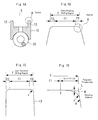
- FIGS. 1A to 1D are cross-sectional views of a two-piece oil ring according to the present invention.
- FIG. 1A is a general view of a two-piece oil ring.
- FIG. 1B is an enlarged view of “A” portion which is equally magnified in the axial and radial directions.
- FIG. 1C is an enlarged view of “A” portion which is magnified 200 times in the axial direction and 2000 times in the radial direction.
- FIG. 1D is an enlarged view of “B” portion which is equally magnified in the axial and radial directions.
- FIGS. 2A and 2B are schematic diagrams to explain the method of grinding the outer periphery of the rail portions of a two-piece oil ring by means of film grinding by using a urethane rubber, according to the first embodiment of the present invention.
- FIG. 2A is a front view and FIG. 2B is a side view.
- FIGS. 3A and 3B are schematic diagrams to explain the method of grinding the outer periphery of the rail portions of a two-piece oil ring by using a buff or an elastic grindstone, according to the second embodiment of the present invention.
- FIG. 3A shows an example where the rotation axis of the jig that is used for mounting oil ring bodies is orthogonal to the rotation axis of the buff or elastic grindstone.
- FIG. 3B shows an example where the rotation axis of the jig is in parallel to the rotation axis of the buff or elastic grindstone.
- FIG. 4 is a schematic diagram that shows the structure of a sliding friction tester.
- FIG. 5 is a graph that shows the results of the sliding friction test, showing the relationship between the length of the nearly straight region (f 1 or f′) of the outer periphery region of the rail portion and the friction mean effective pressure, under the same tension condition.
- FIG. 6 is a graph that shows the results of the sliding friction test, showing the relationship between the contact pressure on the nearly straight region (f 1 or f′) of the outer periphery region of the rail portion and the friction mean effective pressure, under the same tension condition.
- FIG. 7 is a graph that shows the results of the oil consumption test when the length of the outer periphery region (f) of the rail portions including curved regions is same as that of the nearly straight region (f′) of the conventional rail portions.
- FIGS. 8A and 8B are cross-sectional views of a piston in a cylinder, wherein conventional piston rings are mounted on the piston.
- FIG. 8A shows the case where the oil ring is a three-piece type.
- FIG. 8B shows the case where the oil ring is a two-piece type.
- FIG. 8C shows a cross section of the outer peripheral sliding surface of the rail portions of a two-piece type oil ring.
- FIGS. 9A and 9B show details of the outer peripheral sliding surface of conventional oil rings.
- FIG. 9A shows the profile of the outer peripheral sliding surface of rail portions of a three-piece type oil ring.
- FIG. 9B shows the profile of the outer peripheral sliding surface of rail portions of a two-piece type oil ring.
- FIGS. 1A to 1D show the outer peripheral sliding surface of a pair of rail portions formed on a two-piece oil ring body according to the present invention, taken in cross section in the radial direction.
- FIG. 1A is a cross-sectional general view of a two-piece oil ring.
- FIG. 1B is an enlarged view of “A” portion which is equally magnified in the axial and radial directions.
- FIG. 1C is an enlarged view of “A” portion which is magnified 200 times in the axial direction and 2000 times in the radial direction.
- FIG. 1D is an enlarged view of “B” portion which is equally magnified in the axial and radial directions.
- An oil ring 1 comprises an oil ring body 10 having a pair of rail portions 12 formed at upper and lower portions in its axial direction and butt ends (not shown), and a coil expander 20 assembled in inner periphery side of the oil ring body 10 .
- the outer peripheral sliding region of each of the rail portions 12 of the oil ring body 10 is designated by the letter f.
- the oil ring body 10 of the present invention is characterized in that the outer peripheral sliding region (f) has a nearly straight region (f 1 ) in the center and two curved regions (f 2 ) formed on both sides of the nearly straight region (f 1 ).
- “B” portion shown in FIG. 1B is a part of the nearly straight region (f 1 ), and a curved region (f 2 ) extending therefrom.
- the radius of curvature r of the curved region (f 2 ) can be relatively easily measured as shown in FIG. 1C .
- the curved region (f 2 ) is determined by the radius of curvature of the curved region under magnification 200 times in the axial direction and 2000 times in the radial direction, wherein the radius of curvature is designated as r. In another determining way, as shown in FIG.
- the effective region of the curved region (f 2 ) is the region starting at point E that contacts the nearly straight region (f 1 ) and ending at point J, although there is another region ending at point K that does not appear in FIG. 1C under magnification 200 times in the axial direction and 2000 times in the radial direction.
- the region between the points J and K has little effect on friction reduction because the receding distance M in the region with respect to the imaginary straight line L becomes large.
- FIGS. 2A and 2B are schematic diagrams to explain the method of manufacturing a two-piece oil ring according to the first embodiment of the present invention.
- FIG. 2A the structure of upper half of the assembled oil ring bodies is shown in cross section.
- An oil ring machining device 30 has a jig 40 , wherein one end of the jig 40 is connected to a rotation device 42 and another end is supported by a bearing 44 , and the jig 40 is rotated by the rotation device 42 .
- a plurality of oil ring bodies 10 and annular spacers 14 (also called distance collars by those skilled in the art), each having a smaller diameter than the oil ring bodies, are alternately stacked on the jig 40 , and the butt ends are retained such that the outer periphery of the oil ring bodies 10 becomes a circle.
- the assembled oil ring bodies 10 are rotated by the rotation device 42 , and a film 48 on the surface of which hard particles are distributed is interposed between the assembled oil ring bodies 10 and a urethane rubber 46 , and then pressure is applied for grind machining.
- alumina or silicon carbide which are generally used as abrasives can be used.
- the machining of the outer peripheral sliding surface can be done in a shorter time.
- the outer peripheral sliding region of each rail can be machined symmetrically.
- the outer peripheral sliding region can be machined asymmetrically by changing the width S 2 of the annular spacers.
- FIGS. 3A and 3B are schematic diagrams to explain the method of manufacturing a two-piece oil ring according to the second embodiment of the present invention, wherein the structure of the upper half of the assembled oil ring bodies is shown in cross section.
- a machining device according to the present embodiment performs machining by using a buff or an elastic grindstone 50 to form curved regions on both ends of the outer peripheral sliding surface of the rail portions.
- like parts are identified by the same reference numerals as in FIGS. 2A and 2B .
- FIG. 3A an example is shown where the rotation axis of the buff or elastic grindstone 50 is orthogonal to the rotation axis of the jig 40 . In this case, machining can be performed by moving or oscillating the buff or elastic grindstone 50 in the direction of the axis of the jig 40 .
- FIG. 3B an example is shown where the rotation axis of the buff or elastic grindstone 52 is in parallel to the rotation axis of the jig 40 . Also in this case, machining can be performed by moving or oscillating the buff or elastic grindstone 52 in the direction of the axis of the jig 40 .
- two-piece oil ring bodies each having a nominal diameter of 86 mm, a width of 2 mm, and a thickness of 2 mm were formed.
- machining such as outer peripheral lapping, butting end face grinding, and side surface grinding were performed.
- a plurality of samples were manufactured wherein the width (the length in the axial direction) of the outer peripheral sliding surface of rail portions were made in a range of 0.15 to 0.30 mm.
- a film having a width of 50 mm on which alumina particles of #1000 were distributed was interposed between the assembled oil ring bodies and a urethane rubber roller having a Shore hardness of 70 HS, and they were pressed under a load of 100N so that abrasive machining was performed to form curved regions on both ends of the sliding region of the rail portions. At that time, for some samples, oscillating motion with a width of 1 mm per 30 rpm was applied to obtain larger curved regions.
- the profiles of the curved regions can be controlled by varying, for example, machining time or contact pressures.
- the profiles of the curved regions of the samples were classified into three groups according to the radius of curvature of the curved region under magnification 200 times in the axial direction and 2000 times in the radial direction.
- the three groups were; the profiles whose radius of curvature r were equal to or less than 2 mm (samples for comparison), 3 to 4 mm, and 5 to 9 mm (samples of the embodiments).
- the radius of curvature of 3 mm corresponds to 15 micrometers in the axial direction and 1.5 micrometers in the radial direction.
- the radius of curvature of 5 mm corresponds to 50 micrometers in the axial direction and 5 micrometers in the radial direction.
- the samples whose sliding region of rail portions had only nearly straight region were also manufactured as samples of conventional approach for comparison.
- FIG. 4 shows a cross-sectional schematic view of the tester.
- the tester was a single cylinder having a bore diameter of 86 mm and a stroke of 40 mm.
- a piston 62 was reciprocated in a cylinder 60 whose upper part is opened, with no pressure being applied.
- Sliding friction was detected by three piezo type washer load sensors 64 .
- Sliding friction was evaluated by the Friction Mean Effective Pressure (FMEP).
- FMEP Friction Mean Effective Pressure
- the Friction Mean Effective Pressure is expressed as pressure and calculated by dividing the integral of the friction during the reciprocating motion in two rotations by the piston displacement. The operation was conducted at 600 rpm under the condition where adequate amount of low viscosity oil as a lubricant was dropped from above the cylinder, wherein the low viscosity oil was at a level of 6 centistokes at 30 degrees centigrade, and the bore temperature in the stroke center portion was controlled at 30 degrees centigrade.
- FIG. 5 is a graph that shows the results of the above-mentioned sliding friction test under the same tension condition, and shows the relationship between the length of the nearly straight region (f 1 ) of the outer peripheral sliding region of the rail portion and the Friction Mean Effective Pressure thereof. Also shown in the graph are the results for the samples of conventional approach whose outer peripheral sliding region of the rail portion have only the nearly straight region (f′) and do not have curved regions, wherein (f′) is shown on the horizontal axis as in the case with (f 1 ).
- the length of the nearly straight region (f 1 ) and the value of the Friction Mean Effective Pressure of the sliding region of a typical rail portion of conventional approach are each defined as 1, and relative values are shown.
- the Friction Mean Effective Pressure of 0.73 of a typical three-piece type oil ring under the same tension is also shown by a dashed line.
- FIG. 6 is a graph that shows the relationship between the contact pressure applied on the nearly straight regions (f 1 or f′) on the horizontal axis and the Friction Mean Effective Pressure, based on the data shown in FIG. 5 .
- the samples whose radius of curvature r of the curved region were 3 to 4 mm and 5 to 9 mm (samples of the embodiments) under magnification 200 times in the axial direction and 2000 times in the radial direction, it can be seen that the friction was reduced even if the contact pressure was greater than the sample of conventional approach whose contact pressure is defined as 1.0.
- FIG. 7 shows typical test results under a driving condition that is equivalent to the driving at 100 km/h.
- oil consumption under the same tension condition was equivalent to that of the conventional approach.
- the outer peripheral sliding region of the rail portions of an oil ring body such that the outer peripheral sliding region comprises a nearly straight region with a length equal to or more than 0.05 mm in the center, when viewed from the cross section of its radial direction, and two curved regions on both sides of the straight region, oil intake onto the sliding surface is enhanced by the wedging effect, and sliding hydraulic pressure is easily generated even at the oil intake portions because oil films become extremely thin. As a result, friction can be reduced.
Landscapes
- Engineering & Computer Science (AREA)
- General Engineering & Computer Science (AREA)
- Mechanical Engineering (AREA)
- Chemical & Material Sciences (AREA)
- Combustion & Propulsion (AREA)
- Pistons, Piston Rings, And Cylinders (AREA)
Applications Claiming Priority (3)
| Application Number | Priority Date | Filing Date | Title |
|---|---|---|---|
| JP2003-120169 | 2003-04-24 | ||
| JP2003120169A JP4101105B2 (ja) | 2003-04-24 | 2003-04-24 | オイルリング及びその製造方法並びにそれを用いたピストン構造 |
| PCT/JP2004/005606 WO2004094809A1 (ja) | 2003-04-24 | 2004-04-20 | オイルリング及びその製造方法並びにそれを用いたピストン構造 |
Related Parent Applications (1)
| Application Number | Title | Priority Date | Filing Date |
|---|---|---|---|
| PCT/JP2004/005606 Continuation WO2004094809A1 (ja) | 2003-04-24 | 2004-04-20 | オイルリング及びその製造方法並びにそれを用いたピストン構造 |
Publications (2)
| Publication Number | Publication Date |
|---|---|
| US20060081126A1 US20060081126A1 (en) | 2006-04-20 |
| US7797829B2 true US7797829B2 (en) | 2010-09-21 |
Family
ID=33308126
Family Applications (1)
| Application Number | Title | Priority Date | Filing Date |
|---|---|---|---|
| US11/257,377 Expired - Fee Related US7797829B2 (en) | 2003-04-24 | 2005-10-24 | Oil ring, manufacturing method thereof, and piston structure using the oil ring |
Country Status (9)
| Country | Link |
|---|---|
| US (1) | US7797829B2 (pt) |
| EP (1) | EP1617066A1 (pt) |
| JP (1) | JP4101105B2 (pt) |
| KR (1) | KR20060009820A (pt) |
| CN (1) | CN100535425C (pt) |
| BR (1) | BRPI0409709A (pt) |
| RU (1) | RU2005136425A (pt) |
| TW (1) | TW200422517A (pt) |
| WO (1) | WO2004094809A1 (pt) |
Cited By (2)
| Publication number | Priority date | Publication date | Assignee | Title |
|---|---|---|---|---|
| US20100176557A1 (en) * | 2007-06-13 | 2010-07-15 | Esser Peter-Klaus | Oil wiper ring |
| US8690450B2 (en) | 2008-12-15 | 2014-04-08 | Ntn Corporation | Machine component and super-finishing method therefor |
Families Citing this family (8)
| Publication number | Priority date | Publication date | Assignee | Title |
|---|---|---|---|---|
| JP4101105B2 (ja) | 2003-04-24 | 2008-06-18 | 株式会社リケン | オイルリング及びその製造方法並びにそれを用いたピストン構造 |
| JP2007064346A (ja) * | 2005-08-31 | 2007-03-15 | Nippon Piston Ring Co Ltd | 圧力リング及びその製造方法 |
| JP2010031835A (ja) * | 2008-06-23 | 2010-02-12 | Nissan Motor Co Ltd | 内燃機関用オイルリング及びピストン |
| JP5009261B2 (ja) * | 2008-09-30 | 2012-08-22 | 日本ピストンリング株式会社 | オイルリング本体の製造方法 |
| EP2484941B1 (en) * | 2009-09-30 | 2018-04-25 | Nippon Piston Ring Co., Ltd. | Combined oil ring |
| CN112548488B (zh) * | 2020-11-23 | 2021-11-02 | 中船澄西船舶修造有限公司 | 一种大尺寸环形槽的高精度加工方法 |
| CN114235361A (zh) * | 2021-11-30 | 2022-03-25 | 潍柴动力股份有限公司 | 一种发动机活塞及发动机活塞疲劳试验装置 |
| JPWO2024161511A1 (pt) * | 2023-01-31 | 2024-08-08 |
Citations (13)
| Publication number | Priority date | Publication date | Assignee | Title |
|---|---|---|---|---|
| US1933568A (en) * | 1930-07-24 | 1933-11-07 | Walter J Six | Method of making piston rings |
| US2290321A (en) * | 1940-10-21 | 1942-07-21 | Wilkening Mfg Co | Piston ring |
| US2712971A (en) * | 1952-05-17 | 1955-07-12 | Hastings Mfg Co | Piston ring assembly and elements thereof |
| US2967746A (en) * | 1960-07-27 | 1961-01-10 | Wilkening Mfg Co | Piston ring |
| US3435502A (en) * | 1966-05-26 | 1969-04-01 | Hastings Mfg Co | Piston ring and method of manufacture thereof |
| JPH01178274A (ja) | 1988-01-06 | 1989-07-14 | Nitta Ind Corp | ゴルフ練習用眼鏡 |
| JPH0495664A (ja) | 1990-08-13 | 1992-03-27 | Riken Corp | コイルエキスパンダ付鋼製オイルリング |
| JPH0587366A (ja) | 1991-09-26 | 1993-04-06 | Mitsubishi Electric Corp | 空気調和機の室外機 |
| US5966807A (en) * | 1995-08-08 | 1999-10-19 | Quinney; Martin James | Manufacturing piston rings |
| EP1092898A2 (en) | 1999-10-13 | 2001-04-18 | Riken Corporation | Oil control ring for internal combustion engine with dynamically stabilized side rail |
| WO2004094809A1 (ja) | 2003-04-24 | 2004-11-04 | Kabushiki Kaisha Riken | オイルリング及びその製造方法並びにそれを用いたピストン構造 |
| US7077402B2 (en) | 2002-12-18 | 2006-07-18 | Teikoku Piston Ring Co., Ltd. | Combined oil ring |
| US7354045B2 (en) * | 2002-10-29 | 2008-04-08 | Toyota Jidosha Kabushiki Kaisha | Oil ring |
Family Cites Families (3)
| Publication number | Priority date | Publication date | Assignee | Title |
|---|---|---|---|---|
| US2614899A (en) * | 1951-05-07 | 1952-10-21 | Hastings Mfg Co | Piston ring |
| US4522412A (en) * | 1982-10-26 | 1985-06-11 | Keikoku Piston Ring Co., Ltd. | Oil ring with coil expander |
| JPH0721964Y2 (ja) * | 1988-06-07 | 1995-05-17 | 帝国ピストンリング株式会社 | 組合せオイルリングのサイドレール |
-
2003
- 2003-04-24 JP JP2003120169A patent/JP4101105B2/ja not_active Expired - Lifetime
-
2004
- 2004-04-16 TW TW093110715A patent/TW200422517A/zh unknown
- 2004-04-20 EP EP04728418A patent/EP1617066A1/en not_active Withdrawn
- 2004-04-20 WO PCT/JP2004/005606 patent/WO2004094809A1/ja not_active Ceased
- 2004-04-20 KR KR1020057017188A patent/KR20060009820A/ko not_active Ceased
- 2004-04-20 BR BRPI0409709-2A patent/BRPI0409709A/pt not_active Application Discontinuation
- 2004-04-20 RU RU2005136425/06A patent/RU2005136425A/ru not_active Application Discontinuation
- 2004-04-20 CN CNB2004800077953A patent/CN100535425C/zh not_active Expired - Fee Related
-
2005
- 2005-10-24 US US11/257,377 patent/US7797829B2/en not_active Expired - Fee Related
Patent Citations (14)
| Publication number | Priority date | Publication date | Assignee | Title |
|---|---|---|---|---|
| US1933568A (en) * | 1930-07-24 | 1933-11-07 | Walter J Six | Method of making piston rings |
| US2290321A (en) * | 1940-10-21 | 1942-07-21 | Wilkening Mfg Co | Piston ring |
| US2712971A (en) * | 1952-05-17 | 1955-07-12 | Hastings Mfg Co | Piston ring assembly and elements thereof |
| US2967746A (en) * | 1960-07-27 | 1961-01-10 | Wilkening Mfg Co | Piston ring |
| US3435502A (en) * | 1966-05-26 | 1969-04-01 | Hastings Mfg Co | Piston ring and method of manufacture thereof |
| JPH01178274A (ja) | 1988-01-06 | 1989-07-14 | Nitta Ind Corp | ゴルフ練習用眼鏡 |
| JPH0495664A (ja) | 1990-08-13 | 1992-03-27 | Riken Corp | コイルエキスパンダ付鋼製オイルリング |
| JPH0587366A (ja) | 1991-09-26 | 1993-04-06 | Mitsubishi Electric Corp | 空気調和機の室外機 |
| US5966807A (en) * | 1995-08-08 | 1999-10-19 | Quinney; Martin James | Manufacturing piston rings |
| EP1092898A2 (en) | 1999-10-13 | 2001-04-18 | Riken Corporation | Oil control ring for internal combustion engine with dynamically stabilized side rail |
| JP2001108099A (ja) | 1999-10-13 | 2001-04-20 | Riken Corp | 鋼製組み合わせオイルリング |
| US7354045B2 (en) * | 2002-10-29 | 2008-04-08 | Toyota Jidosha Kabushiki Kaisha | Oil ring |
| US7077402B2 (en) | 2002-12-18 | 2006-07-18 | Teikoku Piston Ring Co., Ltd. | Combined oil ring |
| WO2004094809A1 (ja) | 2003-04-24 | 2004-11-04 | Kabushiki Kaisha Riken | オイルリング及びその製造方法並びにそれを用いたピストン構造 |
Non-Patent Citations (2)
| Title |
|---|
| "Internal Combustion Engines-Small Diameter Piston Rings-Part 12: Coil-Spring-Loaded Oil Control Rings," JIS B 8032-12, 1998, 12 pages, Japan. |
| "Internal Combustion Engines-Small Diameter Piston Rings-Part 13: Expander/Segment Oil Control Rings," JIS B 8032-13, 1998, 6 pages, Japan. |
Cited By (3)
| Publication number | Priority date | Publication date | Assignee | Title |
|---|---|---|---|---|
| US20100176557A1 (en) * | 2007-06-13 | 2010-07-15 | Esser Peter-Klaus | Oil wiper ring |
| US8371585B2 (en) * | 2007-06-13 | 2013-02-12 | Federal-Mogul Burscheid Gmbh | Oil wiper ring |
| US8690450B2 (en) | 2008-12-15 | 2014-04-08 | Ntn Corporation | Machine component and super-finishing method therefor |
Also Published As
| Publication number | Publication date |
|---|---|
| US20060081126A1 (en) | 2006-04-20 |
| CN1764776A (zh) | 2006-04-26 |
| KR20060009820A (ko) | 2006-02-01 |
| CN100535425C (zh) | 2009-09-02 |
| EP1617066A1 (en) | 2006-01-18 |
| JP2005113684A (ja) | 2005-04-28 |
| JP4101105B2 (ja) | 2008-06-18 |
| RU2005136425A (ru) | 2006-06-10 |
| WO2004094809A1 (ja) | 2004-11-04 |
| TW200422517A (en) | 2004-11-01 |
| BRPI0409709A (pt) | 2006-05-02 |
Similar Documents
| Publication | Publication Date | Title |
|---|---|---|
| KR101898049B1 (ko) | 조합 오일링 | |
| CA2341723C (en) | Sliding member and piston for internal combustion engine | |
| KR101665491B1 (ko) | 조합형 오일링 | |
| US6902168B2 (en) | Sliding element | |
| EP1377766B1 (en) | Side rail and combined oil control ring incorporated with the side rails for reduction of oil consumption | |
| US7797829B2 (en) | Oil ring, manufacturing method thereof, and piston structure using the oil ring | |
| US7270482B2 (en) | Sliding device | |
| CN113366212B (zh) | 组合油环 | |
| EP2484941A1 (en) | Combined oil ring | |
| CN112703339A (zh) | 组合式活塞环 | |
| CN1306190C (zh) | 具有渗氮表面层的两部件润滑油控制环 | |
| JP2021060048A (ja) | 内燃機関の摺動構造、内燃機関の摺動構造の作り込み方法 | |
| US7207870B1 (en) | Seal assembly manufacturing methods and seal assemblies manufactured thereby | |
| EP4653688A1 (en) | Piston ring and piston ring combination | |
| JP2003328852A (ja) | 内燃機関のピストンリング | |
| JP7368166B2 (ja) | オイルリングの形状作り込み方法、オイルリング | |
| EP3708858B1 (en) | Half thrust bearing, thrust bearing, bearing device, and internal combustion engine | |
| JP5009261B2 (ja) | オイルリング本体の製造方法 | |
| US20250305582A1 (en) | Oil ring and method for manufacturing oil ring | |
| CN120548411A (zh) | 滑动机构 | |
| EP2642093A2 (en) | Rocker arm shaft with improved abrasion resistance and rocker arm shaft/bush assembly comprising same | |
| JP2582093Y2 (ja) | 鋼製オイルコントロールリング | |
| JP2012092928A (ja) | ピストン・シリンダ摺動構造及び該ピストン・シリンダ摺動構造を用いた往復動内燃機関 |
Legal Events
| Date | Code | Title | Description |
|---|---|---|---|
| AS | Assignment |
Owner name: KABUSHIKI KAISHA RIKEN, JAPAN Free format text: ASSIGNMENT OF ASSIGNORS INTEREST;ASSIGNORS:YAMADA, MASAKI;ITO, KUNIYASU;KAWASKI, MASAMI;AND OTHERS;SIGNING DATES FROM 20051115 TO 20051116;REEL/FRAME:017163/0771 Owner name: KABUSHIKI KAISHA RIKEN, JAPAN Free format text: ASSIGNMENT OF ASSIGNORS INTEREST;ASSIGNORS:YAMADA, MASAKI;ITO, KUNIYASU;KAWASKI, MASAMI;AND OTHERS;REEL/FRAME:017163/0771;SIGNING DATES FROM 20051115 TO 20051116 |
|
| STCF | Information on status: patent grant |
Free format text: PATENTED CASE |
|
| FEPP | Fee payment procedure |
Free format text: PAYOR NUMBER ASSIGNED (ORIGINAL EVENT CODE: ASPN); ENTITY STATUS OF PATENT OWNER: LARGE ENTITY |
|
| FPAY | Fee payment |
Year of fee payment: 4 |
|
| MAFP | Maintenance fee payment |
Free format text: PAYMENT OF MAINTENANCE FEE, 8TH YEAR, LARGE ENTITY (ORIGINAL EVENT CODE: M1552) Year of fee payment: 8 |
|
| FEPP | Fee payment procedure |
Free format text: MAINTENANCE FEE REMINDER MAILED (ORIGINAL EVENT CODE: REM.); ENTITY STATUS OF PATENT OWNER: LARGE ENTITY |
|
| LAPS | Lapse for failure to pay maintenance fees |
Free format text: PATENT EXPIRED FOR FAILURE TO PAY MAINTENANCE FEES (ORIGINAL EVENT CODE: EXP.); ENTITY STATUS OF PATENT OWNER: LARGE ENTITY |
|
| STCH | Information on status: patent discontinuation |
Free format text: PATENT EXPIRED DUE TO NONPAYMENT OF MAINTENANCE FEES UNDER 37 CFR 1.362 |
|
| FP | Lapsed due to failure to pay maintenance fee |
Effective date: 20220921 |