US7789357B2 - Rotationally fixed releasable connection between a functional component and a connecting part - Google Patents
Rotationally fixed releasable connection between a functional component and a connecting part Download PDFInfo
- Publication number
- US7789357B2 US7789357B2 US11/788,400 US78840007A US7789357B2 US 7789357 B2 US7789357 B2 US 7789357B2 US 78840007 A US78840007 A US 78840007A US 7789357 B2 US7789357 B2 US 7789357B2
- Authority
- US
- United States
- Prior art keywords
- receiver neck
- insertion element
- mechanical connection
- wedge member
- intermediate wedge
- Prior art date
- Legal status (The legal status is an assumption and is not a legal conclusion. Google has not performed a legal analysis and makes no representation as to the accuracy of the status listed.)
- Expired - Fee Related, expires
Links
- 230000037431 insertion Effects 0.000 claims abstract description 18
- 238000003780 insertion Methods 0.000 claims abstract description 18
- 244000261422 Lysimachia clethroides Species 0.000 claims description 20
- 230000004308 accommodation Effects 0.000 claims 1
- 210000003739 neck Anatomy 0.000 description 16
- 230000000295 complement effect Effects 0.000 description 3
- 229920000114 Corrugated plastic Polymers 0.000 description 1
- 230000006835 compression Effects 0.000 description 1
- 238000007906 compression Methods 0.000 description 1
- 239000012528 membrane Substances 0.000 description 1
- 239000002184 metal Substances 0.000 description 1
Images


Classifications
-
- F—MECHANICAL ENGINEERING; LIGHTING; HEATING; WEAPONS; BLASTING
- F16—ENGINEERING ELEMENTS AND UNITS; GENERAL MEASURES FOR PRODUCING AND MAINTAINING EFFECTIVE FUNCTIONING OF MACHINES OR INSTALLATIONS; THERMAL INSULATION IN GENERAL
- F16B—DEVICES FOR FASTENING OR SECURING CONSTRUCTIONAL ELEMENTS OR MACHINE PARTS TOGETHER, e.g. NAILS, BOLTS, CIRCLIPS, CLAMPS, CLIPS OR WEDGES; JOINTS OR JOINTING
- F16B2/00—Friction-grip releasable fastenings
- F16B2/02—Clamps, i.e. with gripping action effected by positive means other than the inherent resistance to deformation of the material of the fastening
- F16B2/14—Clamps, i.e. with gripping action effected by positive means other than the inherent resistance to deformation of the material of the fastening using wedges
-
- F—MECHANICAL ENGINEERING; LIGHTING; HEATING; WEAPONS; BLASTING
- F16—ENGINEERING ELEMENTS AND UNITS; GENERAL MEASURES FOR PRODUCING AND MAINTAINING EFFECTIVE FUNCTIONING OF MACHINES OR INSTALLATIONS; THERMAL INSULATION IN GENERAL
- F16B—DEVICES FOR FASTENING OR SECURING CONSTRUCTIONAL ELEMENTS OR MACHINE PARTS TOGETHER, e.g. NAILS, BOLTS, CIRCLIPS, CLAMPS, CLIPS OR WEDGES; JOINTS OR JOINTING
- F16B7/00—Connections of rods or tubes, e.g. of non-circular section, mutually, including resilient connections
- F16B7/18—Connections of rods or tubes, e.g. of non-circular section, mutually, including resilient connections using screw-thread elements
-
- F—MECHANICAL ENGINEERING; LIGHTING; HEATING; WEAPONS; BLASTING
- F16—ENGINEERING ELEMENTS AND UNITS; GENERAL MEASURES FOR PRODUCING AND MAINTAINING EFFECTIVE FUNCTIONING OF MACHINES OR INSTALLATIONS; THERMAL INSULATION IN GENERAL
- F16B—DEVICES FOR FASTENING OR SECURING CONSTRUCTIONAL ELEMENTS OR MACHINE PARTS TOGETHER, e.g. NAILS, BOLTS, CIRCLIPS, CLAMPS, CLIPS OR WEDGES; JOINTS OR JOINTING
- F16B47/00—Suction cups for attaching purposes; Equivalent means using adhesives
Definitions
- the invention resides in a rotationally fixed releasable mechanical connection between a functional part and a connecting part with a receiver neck provided on one part and a wedge-like insert element provided on the other part and an engagement means for axially biasing the functional and connecting parts into firm engagement with each other.
- the functional part may for example be a suction mounting socket and the connecting part may be a support structure known for example as a gooseneck.
- the connecting part according to the invention may be used for example in connection with different support devices for navigation apparatus, minicomputers or mobile telephones in motor vehicles by means of suction sockets or sockets mounted firmly at some place in a motor vehicle so that goose necks or other support arms are exchangeable and can selectively be used in the form of longer or shorter arms or other exchangeable support components.
- Apparatus support devices with suction mounting sockets or other mounting structures for example cemented or screwed-on sockets provided with gooseneck support arms are well known in various forms. In all these cases however, the gooseneck is firmly connected to the socket. It is important in that connection that a rotationally fixed connection is established between the socket and the gooseneck since during use substantial forces, in particular torsional forces, are effective. For the needed rigid support of an apparatus however the gooseneck needs to be relatively rigid but should still be bendable by hand.
- the gooseneck generally has a metal wire core which is profiled at the connecting end, for example flattened or provided with a polygonal shape and is received in a mounting socket and engaged therein in a form-locking manner.
- the conventional non-releasable connection between a gooseneck and a mounting part is not without problems, but the problems are generally solved in that, in addition to a form-locking connection, a firm cemented connection is provided between the connecting part specifically between a gooseneck and a functional part such as a mounting socket.
- a connection is to be releasable, it is difficult to provide a connecting structure which can withstand the torsion forces likely to occur during use of the device.
- an intermediate wedge member provided with slightly conical outer surface areas is disposed on the insertion element for reception in the receiver neck which has cooperating inner surfaces with which the wedge member is pressed into firm engagement by a collar disposed on the insertion element which is threaded onto the receiver neck.
- FIG. 1 shows the end piece of a gooseneck and of a suction mounting socket
- FIG. 2 is a side view of the arrangement shown in FIG. 1 ,
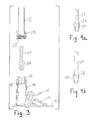
- FIG. 3 is an exploded sectional view of the arrangement according to FIGS. 1 and 2 .
- FIGS. 4 a and 4 b show two different embodiments of a core wire of a gooseneck provided with an end connector piece.
- FIGS. 1 and 2 are perspective and, respectively, side views of a suction mounting socket 1 and an end section of a gooseneck 2 .
- the suction socket 1 includes a suction foot 11 with a circumferentially projecting suction membrane 12 and an operating lever 13 as well as a socket column 14 with a receiver neck 16 provided with an external thread 17 .
- the receiver neck 16 is provided with a conical polygonal profile.
- the gooseneck 2 comprises a core wire 21 , which, as shown in FIGS. 1 and 2 , is in the form of a hexagonal wire and a sleeve 22 in the form of a corrugated plastic tube or similar.
- the shown end piece of the gooseneck is provided with a rotatable threaded collar 23 provided with an internal thread to be threaded onto the external thread 17 of the receiver neck 16 .
- a conical polygonal intermediate wedge member 24 is disposed which has an outer configuration complementary to the inner configuration of the receiver neck 16 .
- FIG. 3 is a sectional view of the suction socket 1 with the connecting structure shown in an exploded state that is the socket and the gooseneck are shown disjointed.
- FIGS. 4 a and 4 b show the core wire alone.
- FIG. 11 a shows the core wire with a hexagonal cross-section and
- FIG. 4 b shows it with a circular cross-section, each with the intermediate wedge member 24 disposed thereon.
- the intermediate wedge member 24 has in each case a polygonal non-conical inner surface which cooperates with a polygonal outer surface of the core wire 21 which (in the embodiment of FIG. 4 a ) is already present or, (in the embodiment of FIG. 4 b with a flattened end) is formed on the end of the core wire 21 .
- the intermediate wedge member 24 may be a slotted sleeve member as apparent from FIGS. 4 a and 4 b so that it can be slipped onto the core wire 21 which is slotted providing for radial resiliency and play-free contact with the core wire 21 .
- a form-locking connection can be established between the intermediate wedge member 24 and the end of the core wire such that the intermediate wedge member 24 is not removable from the core wire 21 , at least not without the application of a substantial force.
- an inner radial flange 25 of the threaded collar 23 cooperates with the rear face 26 at the thicker end of the intermediate wedge member 24 .
- the interior of the receiver neck 16 is complementarily conical to the outer configuration of the intermediate wedge member 24 , the axial compression of the intermediate wedge member 24 in the receiver neck 16 is converted to a radial clamping movement. In this way, a firm radial clamping action of the outer surface of the intermediate wedge member 24 with the inner surface of the receiver neck 16 and also of the inner surface of the intermediate wedge member 24 with the outer surface of the core wire 21 is achieved.
- the intermediate wedge member 24 has on both, the inside and the outside, a polygonal profile and the inner wall of the receiver neck 16 is complementary to the outer surface of the intermediate wedge member and the outer surface of the core wire 21 is complementary to the inner surface of the intermediate wedge member, a strong form-locking rotationally rigid clamping engagement between the various components is achieved without the need for any cementing.
Landscapes
- Engineering & Computer Science (AREA)
- General Engineering & Computer Science (AREA)
- Mechanical Engineering (AREA)
- Mutual Connection Of Rods And Tubes (AREA)
- Hooks, Suction Cups, And Attachment By Adhesive Means (AREA)
- Coupling Device And Connection With Printed Circuit (AREA)
- External Artificial Organs (AREA)
- Pens And Brushes (AREA)
- Dowels (AREA)
- Details Of Connecting Devices For Male And Female Coupling (AREA)
- Connection Of Plates (AREA)
- Snaps, Bayonet Connections, Set Pins, And Snap Rings (AREA)
- Clamps And Clips (AREA)
Applications Claiming Priority (3)
| Application Number | Priority Date | Filing Date | Title |
|---|---|---|---|
| DE202006007040.0 | 2006-04-28 | ||
| DE202006007040U | 2006-04-28 | ||
| DE202006007040U DE202006007040U1 (de) | 2006-04-28 | 2006-04-28 | Drehfeste lösbare mechanische Verbindung zwischen einem Funktionsteil und einem Anschlußteil |
Publications (2)
| Publication Number | Publication Date |
|---|---|
| US20070254537A1 US20070254537A1 (en) | 2007-11-01 |
| US7789357B2 true US7789357B2 (en) | 2010-09-07 |
Family
ID=37026742
Family Applications (1)
| Application Number | Title | Priority Date | Filing Date |
|---|---|---|---|
| US11/788,400 Expired - Fee Related US7789357B2 (en) | 2006-04-28 | 2007-04-19 | Rotationally fixed releasable connection between a functional component and a connecting part |
Country Status (4)
| Country | Link |
|---|---|
| US (1) | US7789357B2 (de) |
| EP (1) | EP1857687B1 (de) |
| AT (1) | ATE453056T1 (de) |
| DE (2) | DE202006007040U1 (de) |
Cited By (3)
| Publication number | Priority date | Publication date | Assignee | Title |
|---|---|---|---|---|
| US20130099075A1 (en) * | 2011-10-21 | 2013-04-25 | Hon Hai Precision Industry Co., Ltd. | Support device |
| US20140340839A1 (en) * | 2013-05-14 | 2014-11-20 | Paul Liniger | Handheld mount and stand assembly for portable electronic devices |
| US20170208997A1 (en) * | 2014-07-18 | 2017-07-27 | Pi-Design Ag | Kitchen appliance for processing foodstuff |
Families Citing this family (2)
| Publication number | Priority date | Publication date | Assignee | Title |
|---|---|---|---|---|
| US20120267406A1 (en) * | 2011-04-25 | 2012-10-25 | Eagle Fan | Suction disc support set with auxiliary tool for emergency escape |
| US20190360648A1 (en) * | 2018-05-22 | 2019-11-28 | Habitex Corporation | Lighting assembly |
Citations (6)
| Publication number | Priority date | Publication date | Assignee | Title |
|---|---|---|---|---|
| US2510198A (en) * | 1947-10-17 | 1950-06-06 | Earl B Tesmer | Flexible positioner |
| US3721463A (en) | 1970-11-23 | 1973-03-20 | Unistrut Corp | Post adapter |
| US4388014A (en) * | 1980-01-26 | 1983-06-14 | Dyckerhoff & Widmann Aktiengesellschaft | Multiple part tapered collar for a tendon anchorage system |
| US5156365A (en) * | 1992-01-21 | 1992-10-20 | Mccaig M Lyle | Table-mountable support for a mannequin-head |
| US6193197B1 (en) * | 1999-12-27 | 2001-02-27 | Bing-Tson Lian | Multipurpose suction-type connection seat |
| US7021593B1 (en) * | 2004-10-26 | 2006-04-04 | Eagle Fan | Vacuum suction apparatus |
Family Cites Families (3)
| Publication number | Priority date | Publication date | Assignee | Title |
|---|---|---|---|---|
| GB833802A (en) * | 1957-06-29 | 1960-04-27 | Bailey Brothers Hot Pressings | Improvements relating to detachable joints for connection rods |
| SE8202020L (sv) * | 1982-03-30 | 1983-10-01 | Fg Autotechnics | Anordning for att lasa temporert ett relativlege mellan tva i forhallande till varandra teleskopartat forskjutbara kroppar |
| DE202004017034U1 (de) * | 2004-11-04 | 2005-03-24 | Eagle Fan Chu Pei | Vakuumsaugvorrichtung |
-
2006
- 2006-04-28 DE DE202006007040U patent/DE202006007040U1/de not_active Expired - Lifetime
-
2007
- 2007-03-23 AT AT07006000T patent/ATE453056T1/de active
- 2007-03-23 DE DE502007002377T patent/DE502007002377D1/de active Active
- 2007-03-23 EP EP07006000A patent/EP1857687B1/de not_active Not-in-force
- 2007-04-19 US US11/788,400 patent/US7789357B2/en not_active Expired - Fee Related
Patent Citations (6)
| Publication number | Priority date | Publication date | Assignee | Title |
|---|---|---|---|---|
| US2510198A (en) * | 1947-10-17 | 1950-06-06 | Earl B Tesmer | Flexible positioner |
| US3721463A (en) | 1970-11-23 | 1973-03-20 | Unistrut Corp | Post adapter |
| US4388014A (en) * | 1980-01-26 | 1983-06-14 | Dyckerhoff & Widmann Aktiengesellschaft | Multiple part tapered collar for a tendon anchorage system |
| US5156365A (en) * | 1992-01-21 | 1992-10-20 | Mccaig M Lyle | Table-mountable support for a mannequin-head |
| US6193197B1 (en) * | 1999-12-27 | 2001-02-27 | Bing-Tson Lian | Multipurpose suction-type connection seat |
| US7021593B1 (en) * | 2004-10-26 | 2006-04-04 | Eagle Fan | Vacuum suction apparatus |
Cited By (4)
| Publication number | Priority date | Publication date | Assignee | Title |
|---|---|---|---|---|
| US20130099075A1 (en) * | 2011-10-21 | 2013-04-25 | Hon Hai Precision Industry Co., Ltd. | Support device |
| US20140340839A1 (en) * | 2013-05-14 | 2014-11-20 | Paul Liniger | Handheld mount and stand assembly for portable electronic devices |
| US9483075B2 (en) * | 2013-05-14 | 2016-11-01 | Paul Liniger | Handheld mount and stand assembly for portable electronic devices |
| US20170208997A1 (en) * | 2014-07-18 | 2017-07-27 | Pi-Design Ag | Kitchen appliance for processing foodstuff |
Also Published As
| Publication number | Publication date |
|---|---|
| ATE453056T1 (de) | 2010-01-15 |
| US20070254537A1 (en) | 2007-11-01 |
| DE202006007040U1 (de) | 2006-09-07 |
| EP1857687A2 (de) | 2007-11-21 |
| EP1857687A3 (de) | 2007-12-26 |
| EP1857687B1 (de) | 2009-12-23 |
| DE502007002377D1 (de) | 2010-02-04 |
Similar Documents
| Publication | Publication Date | Title |
|---|---|---|
| US7152834B2 (en) | Adjustable attachment device for attaching an object to a tubular member | |
| US20070254537A1 (en) | Rotationally fixed releasable connection between a functional component and a connecting part | |
| JP5538548B2 (ja) | シールドケーブル用のケーブルグランド | |
| CN102823093A (zh) | 具有用于电缆的铠装件的夹紧装置的电缆螺纹接头 | |
| US9016971B2 (en) | Motor vehicle elastic suspension joint and motor vehicle structure comprising such a joint | |
| CN101262969A (zh) | 用于两个构件的可拆联接的装置 | |
| JP2009090754A (ja) | スイッチボディの取付構造 | |
| US6519813B1 (en) | Fixing device for a pen clip | |
| US9873385B2 (en) | Bicycle mounting adapter | |
| US10498076B2 (en) | Connector assembly connecting cables for power transmission | |
| JP3897796B2 (ja) | 車両用アンテナの取付構造 | |
| KR20090018362A (ko) | 텔레스코프 조향장치 | |
| KR101172116B1 (ko) | 텔레스코프 조향장치 | |
| JP2963849B2 (ja) | 軸体の嵌合構造 | |
| JPH0747823Y2 (ja) | 同軸ケーブル用コネクターの外部導体締付具 | |
| JP2008525269A (ja) | ワイパ装置 | |
| JP3845628B2 (ja) | 車両用可倒式アンテナ | |
| CN206036467U (zh) | 具有螺纹接套和压缩套管的软管连接装置 | |
| CN216761607U (zh) | 车身配件安装结构及车辆 | |
| JP2503959Y2 (ja) | フレキシブルスタンド | |
| JP5195267B2 (ja) | 車両用ステアリング装置 | |
| JPH11253373A5 (de) | ||
| JPH0516498Y2 (de) | ||
| KR101172099B1 (ko) | 텔레스코프 조향장치 | |
| US20040255777A1 (en) | Pneumatic brake booster provided with a control rod and method for mounting same |
Legal Events
| Date | Code | Title | Description |
|---|---|---|---|
| FPAY | Fee payment |
Year of fee payment: 4 |
|
| FEPP | Fee payment procedure |
Free format text: MAINTENANCE FEE REMINDER MAILED (ORIGINAL EVENT CODE: REM.) |
|
| LAPS | Lapse for failure to pay maintenance fees |
Free format text: PATENT EXPIRED FOR FAILURE TO PAY MAINTENANCE FEES (ORIGINAL EVENT CODE: EXP.); ENTITY STATUS OF PATENT OWNER: SMALL ENTITY |
|
| STCH | Information on status: patent discontinuation |
Free format text: PATENT EXPIRED DUE TO NONPAYMENT OF MAINTENANCE FEES UNDER 37 CFR 1.362 |
|
| FP | Lapsed due to failure to pay maintenance fee |
Effective date: 20180907 |