US7779834B2 - Method and apparatus for substance delivery in system for supplying breathable gas - Google Patents
Method and apparatus for substance delivery in system for supplying breathable gas Download PDFInfo
- Publication number
- US7779834B2 US7779834B2 US11/237,830 US23783005A US7779834B2 US 7779834 B2 US7779834 B2 US 7779834B2 US 23783005 A US23783005 A US 23783005A US 7779834 B2 US7779834 B2 US 7779834B2
- Authority
- US
- United States
- Prior art keywords
- substance
- pressure
- breathable gas
- animal
- human
- Prior art date
- Legal status (The legal status is an assumption and is not a legal conclusion. Google has not performed a legal analysis and makes no representation as to the accuracy of the status listed.)
- Expired - Fee Related, expires
Links
Images


Classifications
-
- A—HUMAN NECESSITIES
- A61—MEDICAL OR VETERINARY SCIENCE; HYGIENE
- A61M—DEVICES FOR INTRODUCING MEDIA INTO, OR ONTO, THE BODY; DEVICES FOR TRANSDUCING BODY MEDIA OR FOR TAKING MEDIA FROM THE BODY; DEVICES FOR PRODUCING OR ENDING SLEEP OR STUPOR
- A61M16/00—Devices for influencing the respiratory system of patients by gas treatment, e.g. ventilators; Tracheal tubes
- A61M16/10—Preparation of respiratory gases or vapours
- A61M16/14—Preparation of respiratory gases or vapours by mixing different fluids, one of them being in a liquid phase
-
- A—HUMAN NECESSITIES
- A61—MEDICAL OR VETERINARY SCIENCE; HYGIENE
- A61M—DEVICES FOR INTRODUCING MEDIA INTO, OR ONTO, THE BODY; DEVICES FOR TRANSDUCING BODY MEDIA OR FOR TAKING MEDIA FROM THE BODY; DEVICES FOR PRODUCING OR ENDING SLEEP OR STUPOR
- A61M15/00—Inhalators
- A61M15/0065—Inhalators with dosage or measuring devices
- A61M15/0066—Inhalators with dosage or measuring devices with means for varying the dose size
-
- A—HUMAN NECESSITIES
- A61—MEDICAL OR VETERINARY SCIENCE; HYGIENE
- A61M—DEVICES FOR INTRODUCING MEDIA INTO, OR ONTO, THE BODY; DEVICES FOR TRANSDUCING BODY MEDIA OR FOR TAKING MEDIA FROM THE BODY; DEVICES FOR PRODUCING OR ENDING SLEEP OR STUPOR
- A61M16/00—Devices for influencing the respiratory system of patients by gas treatment, e.g. ventilators; Tracheal tubes
- A61M16/10—Preparation of respiratory gases or vapours
- A61M16/14—Preparation of respiratory gases or vapours by mixing different fluids, one of them being in a liquid phase
- A61M16/147—Preparation of respiratory gases or vapours by mixing different fluids, one of them being in a liquid phase the respiratory gas not passing through the liquid container
-
- A—HUMAN NECESSITIES
- A61—MEDICAL OR VETERINARY SCIENCE; HYGIENE
- A61M—DEVICES FOR INTRODUCING MEDIA INTO, OR ONTO, THE BODY; DEVICES FOR TRANSDUCING BODY MEDIA OR FOR TAKING MEDIA FROM THE BODY; DEVICES FOR PRODUCING OR ENDING SLEEP OR STUPOR
- A61M15/00—Inhalators
- A61M15/0065—Inhalators with dosage or measuring devices
-
- A—HUMAN NECESSITIES
- A61—MEDICAL OR VETERINARY SCIENCE; HYGIENE
- A61M—DEVICES FOR INTRODUCING MEDIA INTO, OR ONTO, THE BODY; DEVICES FOR TRANSDUCING BODY MEDIA OR FOR TAKING MEDIA FROM THE BODY; DEVICES FOR PRODUCING OR ENDING SLEEP OR STUPOR
- A61M16/00—Devices for influencing the respiratory system of patients by gas treatment, e.g. ventilators; Tracheal tubes
- A61M16/0003—Accessories therefor, e.g. sensors, vibrators, negative pressure
- A61M2016/0015—Accessories therefor, e.g. sensors, vibrators, negative pressure inhalation detectors
- A61M2016/0018—Accessories therefor, e.g. sensors, vibrators, negative pressure inhalation detectors electrical
- A61M2016/0021—Accessories therefor, e.g. sensors, vibrators, negative pressure inhalation detectors electrical with a proportional output signal, e.g. from a thermistor
-
- A—HUMAN NECESSITIES
- A61—MEDICAL OR VETERINARY SCIENCE; HYGIENE
- A61M—DEVICES FOR INTRODUCING MEDIA INTO, OR ONTO, THE BODY; DEVICES FOR TRANSDUCING BODY MEDIA OR FOR TAKING MEDIA FROM THE BODY; DEVICES FOR PRODUCING OR ENDING SLEEP OR STUPOR
- A61M16/00—Devices for influencing the respiratory system of patients by gas treatment, e.g. ventilators; Tracheal tubes
- A61M16/0003—Accessories therefor, e.g. sensors, vibrators, negative pressure
- A61M2016/003—Accessories therefor, e.g. sensors, vibrators, negative pressure with a flowmeter
- A61M2016/0033—Accessories therefor, e.g. sensors, vibrators, negative pressure with a flowmeter electrical
- A61M2016/0039—Accessories therefor, e.g. sensors, vibrators, negative pressure with a flowmeter electrical in the inspiratory circuit
-
- A—HUMAN NECESSITIES
- A61—MEDICAL OR VETERINARY SCIENCE; HYGIENE
- A61M—DEVICES FOR INTRODUCING MEDIA INTO, OR ONTO, THE BODY; DEVICES FOR TRANSDUCING BODY MEDIA OR FOR TAKING MEDIA FROM THE BODY; DEVICES FOR PRODUCING OR ENDING SLEEP OR STUPOR
- A61M16/00—Devices for influencing the respiratory system of patients by gas treatment, e.g. ventilators; Tracheal tubes
- A61M16/0003—Accessories therefor, e.g. sensors, vibrators, negative pressure
- A61M2016/003—Accessories therefor, e.g. sensors, vibrators, negative pressure with a flowmeter
- A61M2016/0033—Accessories therefor, e.g. sensors, vibrators, negative pressure with a flowmeter electrical
- A61M2016/0042—Accessories therefor, e.g. sensors, vibrators, negative pressure with a flowmeter electrical in the expiratory circuit
Definitions
- the present invention relates to a substance delivery apparatus for use with a system for supplying breathable gas to a human or animal.
- CSA Obstructive Sleep Apnea
- CPAP Continuous Positive Airway Pressure
- the pressure of the gas delivered to patients can be constant level, bi-level (in synchronism with patient inspiration) or auto setting in level.
- CPAP is intended to incorporate a reference to any one of, or combinations of, these forms of pressurised gas supply.
- the present invention provides a substance delivery apparatus for use with a system for supplying breathable gas to a human or animal, the apparatus including:
- the invention provides a method of delivering a substance to a human or animal being supplied with breathable gas, the method includes the steps of:
- the substance is preferably a medicinal substance and, desirably, in the form of a gas, mist, aerated suspension, jet, spray, gas mixture or the like.
- the substance is preferably delivered to the respiratory system of the human or animal and, in particular, to the nasal airways.
- the supplied breathable gas is preferably pressurised above atmospheric pressure.
- the system for supplying the breathable gas preferably includes a pressurized gas flow generator in fluid communication with a mask worn by the human or animal is via a flexible conduit, and the inhalation detection means includes an airflow sensor adapted to measure the volumetric flow rate of the breathable gas passing through the conduit and generate a first input signal indicative of the breathable gas flow rate.
- mask is herein understood to include facemasks, nosemasks, mouthmask, apenditures in the vicinity of any of these masks and the like.
- the first signal is preferably amplified by a first amplifer into a second input signal also indicative of the gas flow rate.
- a derivative of the first signal is also generated by a differentiating filter to determine the acceleration or deceleration of the gas, which is indicative of inhalation or exhalation respectively, and is represented by a third input signal.
- inhalation can be detected by sensing a reversal of the direction of the gas flow through the vent. Inhalation can also be detected by sensing an interruption of the gas flow.
- the apparatus preferably also includes means to measure the volume of the substance to be delivered to the human or animal.
- the pressure measuring means is preferably a pressure transducer connected to the conduit which is adapted to generate a fourth input signal indicative of the pressure of the gas in the conduit.
- the fourth input signal is preferably amplified by a second amplifier into a fifth input signal also indicative of the as pressure.
- the substance delivery means is preferably a positive displacement pump, most preferably a diaphragm pump.
- the diaphragm pump is desirably in fluid communication with a substance reservoir via a one-way valve adapted to allow the substance to only pass from the reservoir to the pump.
- the pump is preferably also in fluid communication with the gas supply conduit via a one-way valve adapted to allow the substance to only pass from the pump to the conduit.
- the diaphragm of the pump is desirably displaced by a linear drive means which, in one form, may take the form of an electromagnet.
- a rotary drive means such as an electric DC motor, an electric AC motor, a stepper motor, or a brushless motor are used with a rotary to linear converter interposed between the rotary drive means and the diaphragm pump.
- the apparatus preferably also includes a first control system adapted to receive the second, third and fourth input signals.
- the control system preferably also includes input means adapted to allow the input of a predetermined sixth input indicative of the volume of the substance to be delivered and a predetermined seventh input signal indicative of the amount by which the pressure of the delivered substance should exceed the pressure of the supplied breathable gas.
- the first control system is preferably adapted to receive the second, third, fifth, sixth and seventh input signals to calculate and generate a first output signal indicative of the amount of displacement of the linear or rotary drive means and a second output signal indicative of the direction of the displacement required to produce negative or positive pumping pressure.
- the first and second output signals are preferably sent to a second control system which converts them into third and fourth output signals indicative of drive means displacement and direction respectively, the third and fourth output signals being compatible with the linear or rotary drive means.
- the first and second output signals are sent to a second control system adapted to convert them into third and fourth output signals indicative of drive means displacement and direction respectively, the third and fourth output signals being compatible with the linear or rotary drive means.
- the input and output signals can be analog, digital or the like.
- CPAP Continuous Positive Airway Pressure
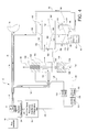
- FIG. 1 is a schematic diagram of a substance delivery apparatus according to a first embodiment of the invention
- FIG. 2 is a schematic diagram of a substance delivery apparatus according to a second embodiment of the invention.
- FIG. 3 is a schematic diagram of a substance delivery apparatus according to a third embodiment of the invention.
- FIG. 4 is a schematic diagram of the apparatus of FIG. 3 during inhalation
- FIG. 5 is a schematic diagram of the apparatus shown in FIG. 3 during exhalation
- FIG. 6 is a partial schematic diagram of a substance delivery apparatus according to a fourth embodiment of the invention.
- FIGS. 7 a , 7 b and 7 c are partial schematic diagrams of a substance delivery apparatus according to a fifth embodiment of the invention.
- FIG. 1 there is shown a first embodiment of a substance delivery apparatus 10 according to the invention.
- the apparatus 10 is used with a system, indicated generally at 12 , for supplying air, indicated by arrow 14 , to a human patient (not shown).
- the system 12 includes a pressurized gas flow generator 16 in fluid communication with a mask 18 via conduit 20 .
- Mask 18 includes a gas washout vent 19 .
- the apparatus 10 includes a means to measure the pressure of the air 14 and to detect patient inhalation, in the form of an air flow sensor 22 .
- the sensor 22 is interposed in the conduit 20 between the mask 18 and the pressurised gas flow generator 16 .
- the airflow sensor 22 in the form of a fixed orifice, is connected to an electronic flow transducer 24 .
- a variable orifice, venturi tube, Pitot tube or tubes bundle can also be used to sense airflow.
- the transducer 24 generates a first electrical input signal 26 indicative of the flow rate of the air 14 passing through the conduit 20 which is sent to a first flow signal processing amplifier and differentiating filter 28 which in turn generates second and third input signals 30 and 32 respectively.
- the second input signal 30 is an amplified version of the first input signal 26 .
- the third input signal 32 is the derivative of the first signal 26 , with acceleration and deceleration being respectively indicative of inhalation or exhalation.
- acceleration and deceleration being respectively indicative of inhalation or exhalation.
- An air pressure transducer 34 is also connected to the conduit 20 and generates a fourth electrical input signal 36 indicative of the pressure in the conduit.
- the fourth signal 36 is delivered to an air pressure processing amplifier 38 which generates a fifth input signal 40 also indicative of the pressure in the conduit 20 .
- the second, third and fifth input signals 30 , 32 and 40 are fed to a first control system 42 .
- the first control system 42 also receives sixth and seventh predetermined input signals 44 and 46 from manual inputs 48 and 50 in the form of potentiometers accessible by a system operator. Variable resistors car, also be used as the manual inputs.
- the sixth input signal 44 is indicative of the volume of substance to be delivered to the mask during each inhalation cycle of the patient.
- the seventh signal 46 is indicative of the amount by which the delivery pressure of the substance is to exceed the measured pressure of the air 14 in the conduit 20 .
- the means to deliver a substance 52 to the mask 18 includes a substance reservoir 54 connected by conduit 56 to diaphragm pump 58 having a flexible diaphragm 60 .
- a one way valve 62 is interposed between the reservoir 54 and pump 58 and permits the substance 52 to only enter the pump 58 .
- the pump 58 is in fluid communication with the conduit 20 by virtue of conduit branch 64 and one way valve 66 which allows the substance 52 to pass from the pump 58 to the conduit 20 .
- the stroke of the diaphragm 60 is controlled by an electromagnet drive means 68 , in the form of a magnet 70 connected to the centre of the diaphragm 60 and surrounded by electrical windings 72 .
- the drive means 68 are controlled by a second control system 74 .
- the first control system 42 In response to receiving the second, third, fifth, sixth and seventh input signals, the first control system 42 generates first and second output signals 76 and 78 , respectively indicative of the electromagnet displacement magnitude and direction. Displacement in the direction of arrow 80 draws the substance 52 into the pump 58 . Displacement in the direction of arrow 82 causes the substance 52 to be pumped into the conduit branch 64 and thereafter the conduit 20 .
- the output signals 76 and 78 are received by the second control system 74 which issues third and fourth output signals 84 and 86 respectively, which are compatible with the drive means 68 .
- the third output signal 84 is indicative of the amount of displacement of the electromagnet 68 and the fourth signal 86 is indicative of the displacement direction.
- breathable air 14 is supplied by the gas flow generator 16 to the mask 18 via the conduit 20 ) so the patient may breathe.
- an analogue to digital converter in the control system 42 samples the air flow information of the second input signal 30 over a few breaths and stores it in a memory (not shown).
- the stored values are integrated with respect, to the time of the inhalation portion of their respective breathing cycle.
- the integrated value is the tidal volume of each breath and is also stored in the memory.
- the stored values of the tidal volume are averaged over a small number of breaths to provide an average value of the tidal volume.
- the control system 42 calculates the magnitude of the current to be applied to the windings 72 of the diaphragm pump 58 .
- the control systems 42 and is 74 calculate and issue the third and fourth output signals 84 and 86 to the windings 72 .
- the direction of the current applied to the windings 72 causes the magnet 70 and the diaphragm 60 to be displaced in the direction of the arrow 80 to the position shown by phantom line 87 .
- This movement of the diaphragm 60 draws the substance 52 past the one way valve 63 and into the pump 58 .
- the magnitude of the current applied to windings 72 is proportional to the displacement of the diaphragm 60 and also therefore the volume of gas drawn into the pump 58 which is delivered to the patient during the next inhalation cycle.
- the current applied to the windings 72 remains constant and the magnet 70 and diaphragm 60 remain as indicated by line 87 .
- the control system 42 and 74 When the third input signal 32 indicates inhalation, the control system 42 and 74 reverse the current flowing into the windings 72 , thereby displacing the magnet 70 and the diaphragm 60 in the direction indicated by the arrow 82 to the position shown by phantom line 89 . This movement forces the substance 52 from the pump 53 through the one way valve 68 and conduit branch 64 into the mask 18 .
- the air pressure of the gas 14 in the conduit 20 is exceeded by the pressure of the substance pumped through conduit branch 64 .
- the supply pressure of the substance 52 is calculated by the control system 42 and is the sum of the pressure measured by pressure transducer 34 in conduit 20 and the pressure increment set by manual input 50 .
- the substance 52 is then delivered to the patient via the conduit 64 and the mask 18 .
- FIG. 2 A second embodiment of the present invention is shown in FIG. 2 , in which like reference numerals are used to indicate like features.
- the first control system 42 of the second embodiment incorporates a microcontroller 92 and a linear position transducer 94 connected to the magnet 70 to provide a feedback signal 96 indicative of the position of the magnet 70 and the diaphragm 60 , to which it is connected.
- the two manual inputs 48 and 50 are replaced by a digital control panel 98 with: a three digit digital display 100 ; three push buttons: Mode 102 , “+” 104 , “ ⁇ ” 106 ; and three LEDs to indicate the mode selected: Volume 108 , Delivery Pressure 110 and Run 112 .
- Mode push button 102 Successive depression of the Mode push button 102 cycles through the three modes of operation: Volume, Delivery Pressure and Run.
- the digital display 100 When Volume or Delivery Pressure is selected, the digital display 100 indicates the current setting of that parameter. This value may be modified if required by operating either of the two push buttons “+” 104 or “ ⁇ ” 106 .
- the parameters stored in the memory of the microcontroller 90 calculate the desired position of the magnet 70 . This is then compared with the actual magnet position indicated by the linear position transducer 94 . Any difference produces an error signal that is used to correct the position of the magnet 70 to the desired position,
- FIGS. 3 to 5 A third embodiment of the present invention is shown in FIGS. 3 to 5 , in which like reference numerals are again used to indicate like features.
- the flow processing amplifier and differentiating filter 28 again detects the onset of inhalation by sensing a change in the rate of flow (ie. the acceleration or deceleration) of the gas flowing past the sensor 22 .
- the output signal 120 from the amplifier filter 28 of this embodiment is active when the onset of inhalation is detected and remains active for the duration of the inhalation portion of the breathing cycle.
- the output signal 120 from the amplifier filter 28 is not active for the exhalation portion of the breathing cycle.
- the output signal 120 is supplied to a driver stage 122 and an inverter stage 124 .
- the driver stage 122 When the output signal 120 is active, during inhalation, the driver stage 122 is active and applies power to an electromagnetic winding 126 through a connection 128 .
- the inverter stage 124 supplies a drive signal 130 to a driver stage 132 .
- the driver sage 132 is activated and supplies power to an electromagnetic winding 134 through a connection 136 .
- a magnetic core 138 is located within the electromagnetic winding 126 .
- a magnetic core 140 is located within the electromagnetic winding 134 .
- the magnetic core 138 and the magnetic core 140 are connected by a connecting rod 142 which is also connected to a sliding spool valve 144 .
- connection 136 When winding 134 is energised through connection 136 the magnetic core 140 is displaced in the direction of arrow 152 and pulls with it the spool valve 144 and core 138 .
- the body 154 of the spool valve 144 is connected to the gas flow generator 16 through a branch conduit 156 connected to the conduit 20 .
- a diaphragm motor 157 is comprised of housing halves 158 and 160 separated by a diaphragm 162 which defines cavities 164 and 166 .
- a diaphragm pump 168 is comprised of housing halves 170 and 172 separated by a diaphragm 174 which defines cavities 176 and 178 .
- the cavity 164 is connected to the spool valve body 154 by a conduit 182 .
- the cavity 166 is connected to the spool valve body 154 by a conduit 184 .
- the cavity 176 is open to atmosphere.
- the cavity 178 is connected to the source 54 of the substance 52 to be delivered by the conduit 56 and the one-way valve 62 .
- the cavity 178 is also connected to the mask 18 by the conduit 64 and the one-way valve 66 .
- the motor diaphragm 162 and the pump diaphragm 174 are connected by a connecting rod 186 .
- the connecting rod 186 passes through an air sealed bearing (not shown) between cavities 166 and 176 .
- An adjusting screw 188 is located on the top of housing halve 158 .
- the second output signal 120 from the flow processing amplifier 28 is set to active and activates the driver stage 122 .
- the inverter stage 124 is inactive and magnetic core 140 is free to move.
- the driver stage 122 supplies power to the electromagnetic winding 126 through connection 128 .
- the magnetic core 138 is forced in the direction of the arrow 150 and with it the spool valve 144 .
- the air 14 now flows from the branch conduit 156 into the spool valve body 154 and is diverted by the spool valve 144 through the conduit 182 and into the cavity 164 .
- the pressure of the air entering the cavity 164 forces the motor diaphragm 162 in the direction of arrow 190 and with it the pump diaphragm 174 .
- the cavity 178 is already filled with the substance 52 to be delivered to the mask 18 .
- the displacement of the pump diaphragm 174 into the cavity 178 increases the substance pressure, closes the one-way valve 62 , opens the one-way valve 66 , and forces the substance 52 into the conduit 64 .
- the conduit 64 is in fluid communication with the conduit 20 and the mask 18 and the substance 52 is thereby delivered to the mask 18 and the patient.
- the second output signal 120 from the flow processing amplifier 28 is set to inactive.
- the driver stage 122 is not activated and power is not supplied to the electromagnetic winding 126 through connection 128 .
- the magnetic core 138 is therefore free to move.
- the inverter stage 124 turns its output signal to active and activates the driver stage 132 .
- the driver stage 132 supplies power to the electromagnetic winding 134 through the connection 136 and the magnetic core 140 is forced in the direction of the arrow 152 and with it the spool valve 144 .
- the air flows from the branch conduit 156 into the spool valve body 154 and is diverted by the spool valve 144 through the conduit 184 into the cavity 166 .
- the pressure of the air in the cavity 166 forces the motor diaphragm 162 in the direction of arrow 192 and with it the pump diaphragm 174 .
- the displacement of pump diaphragm 174 into cavity 176 produces a vacuum in cavity 178 , closes the one-way valve 66 , opens the one-way valve 62 , and draws the substance 52 through the conduit 56 into the cavity 178 .
- the movement of the motor diaphragm 162 and pump diaphragm 174 is limited by the adjusting screw 188 .
- the setting of the screw 188 governs the maximum displacement of the motor diaphragm 162 and pump diaphragm 174 in direction of the arrow 192 , therefore controlling the volume of the substance 52 able to be drawn into the cavity 178 for delivery to the patient during the next inhalation.
- the pump diaphragm 174 is smaller in area than the motor diaphragm 162 . Accordingly, a given pressure supplied to motor diaphragm 162 will produce a greater pressure from the pump diaphragm 174 . Therefore, the pressure delivered by the pump diaphragm 174 into the conduit 64 and the patient mask 18 will always exceed the pressure of the gas in the conduit 20 .
- the ratio between the pressure in the conduit 20 and the conduit 64 is proportional to the ratio between the area of the diaphragms 174 and 162 .
- the diaphragm motor 157 is replaced by an electric motor, such as a stepper motor, controlled by a control system to provide more accurate delivery of the substance 52 .
- FIG. 6 A fourth embodiment of the present invention is shown in FIG. 6 , in which like reference numerals are again used to indicate like features.
- This embodiment is for use in conjunction with a bi-level CPAP flow generator (not shown) that delivers breathable gas at a relatively high treatment pressure to the mask during patient inhalation and at a relatively low treatment pressure during exhalation.
- a bi-level CPAP flow generator (not shown) that delivers breathable gas at a relatively high treatment pressure to the mask during patient inhalation and at a relatively low treatment pressure during exhalation.
- the applicant markets such a bi-level system under the trade mark VPAP.
- This embodiment includes a motor cylinder 200 having a slidable piston 202 which defines cavities 204 and 206 .
- a pump cylinder 208 is also provided having a slidable piston 210 which defines cavities 212 and 214 .
- the pistons 202 and 210 are connected by a connecting rod 216 which passes through an air sealed bearing 218 .
- the cavity 204 is connected to the conduit 20 by the branch conduit 156 .
- the cavities 206 and 212 are open to atmosphere.
- the cavity 214 is connected to the source 54 of the substance 52 by Me conduit 56 via the one-way valve 62 .
- the cavity 214 is also connected to the mask 18 by the conduit 64 and the one-way valve 66 .
- the pistons are biased in the direction of arrow 220 by a spring 222 .
- conduit 20 which generates only a small amount of force on the piston 202 .
- the spring 222 overcomes this force and drives the pistons 202 and 210 in the direction of the arrow 220 thereby creating a vacuum in cavity 214 .
- the vacuum draws the substance 52 past the one-way valve 62 and into the cavity 214 .
- the surface area of the piston 202 is larger than that of the piston 210 and the pressure generated by the piston 210 will therefore exceed that applied to the piston 202 . Accordingly, the substance delivery pressure will always exceed the pressure produced by the flow generator during the inhalation phase of the breathing cycle.
- the ratio between the surface areas of the pistons 202 and 210 is proportional to the ratio between the breathable gas pressure and the substance delivery pressure.
- FIGS. 7 a , 7 b and 7 c A fifth embodiment of the present invention is shown in FIGS. 7 a , 7 b and 7 c .
- the fifth embodiment is essentially a modification of the fourth embodiment so it will work with a constant pressure flow generator.
- the fifth embodiment includes a control valve 230 interposed between the conduit 20 and the motor cylinder 200 .
- the valve 230 includes an inlet 232 connected to the conduit 20 , a first outlet 234 connected to the cavity 204 and a second outlet 236 open to atmosphere.
- the valve 230 is controlled by an electronic valve controller 238 which receives a signal 240 indicative of inhalation or exhalation, as discussed with respect to earlier embodiments.
- the controller 238 causes the valve 230 to move to the position indicated in FIG. 7 b . In this position, the air 14 is diverted into the cavity 204 causing the pistons to move in the direction of the arrow 224 and the substance 52 to be pumped into the mask 18 , as previously described.
- the controller 238 causes the valve 230 to move to the position shown in FIG. 7 c .
- the air in the cavity 204 is vented to atmosphere as the pistons move in the direction of the arrow 220 under the influence of the spring 2227 .
- this movement also causes the substance 52 to be drawn into the cavity 214 .
- the present invention provides a measured substance dose to a human or animal during inspiration only, thereby greatly reducing drug wastage.
- the preferred apparatus also allows the substance to be delivered to the patient without interrupting CPAP, or similar treatment, or sleep, thereby increasing patient comfort and convenience.
- the preferred apparatus also obviates the need for a patient to remember to take medicine.
Landscapes
- Health & Medical Sciences (AREA)
- Engineering & Computer Science (AREA)
- Life Sciences & Earth Sciences (AREA)
- Anesthesiology (AREA)
- Pulmonology (AREA)
- Biomedical Technology (AREA)
- Heart & Thoracic Surgery (AREA)
- Hematology (AREA)
- Animal Behavior & Ethology (AREA)
- General Health & Medical Sciences (AREA)
- Public Health (AREA)
- Veterinary Medicine (AREA)
- Emergency Medicine (AREA)
- Biophysics (AREA)
- Bioinformatics & Cheminformatics (AREA)
- Measurement Of The Respiration, Hearing Ability, Form, And Blood Characteristics Of Living Organisms (AREA)
Abstract
A substance delivery apparatus for use with a system for supplying breathable gas to a human or animal includes a sensor to measure the pressure of the supplied breathable gas and to detect inhalation by the human or animal; and a reservoir, a conduit, a pump, and a diaphragm to deliver the substance to the human or animal during inhalation at a pressure higher than the supplied pressure of the breathable gas.
Description
This is a continuation of application Ser. No. 09/466,971, filed Dec. 20, 1999, now U.S. Pat. No. 6,990,977, which is a continuation of application Ser. No. 08/989,150, filed Dec. 12, 1997, now U.S. Pat. No. 6,029,660, which claims priority to Australian Application No. PO4186, filed Dec. 12, 1996, each incorporated herein by reference in its entirety.
The present invention relates to a substance delivery apparatus for use with a system for supplying breathable gas to a human or animal.
Treatment of Obstructive Sleep Apnea (CSA) with Continuous Positive Airway Pressure (CPAP) flow generator systems involves the continuous delivery of a breathable gas (generally air) pressurised above atmospheric pressure to a patient's airways via a conduit and a mask. CPAP pressures of 4 cm H2O to 22 cm H2O are typically used for treatment of OSA, depending on patient requirements. Treatment pressures for assisted ventilation can range of up to 32 cm H2O and beyond, again depending on patient requirements.
For either the treatment of OSA or the application of assisted ventilation or similar, the pressure of the gas delivered to patients can be constant level, bi-level (in synchronism with patient inspiration) or auto setting in level. Throughout the specification reference to CPAP is intended to incorporate a reference to any one of, or combinations of, these forms of pressurised gas supply.
It is difficult to administer substances such as medicines to patients undergoing CPAP treatment without interrupting the treatment by removing the gas supply mask.
It is an object of the present invention to ameliorate the above disadvantage.
In a first aspect, the present invention provides a substance delivery apparatus for use with a system for supplying breathable gas to a human or animal, the apparatus including:
means to measure the pressure of the supplied breathable gas;
means to detect inhalation by the human or animal; and
means to deliver the substance to the human or animal during inhalation at a pressure higher than the supplied pressure of the breathable gas.
In a second aspect the invention provides a method of delivering a substance to a human or animal being supplied with breathable gas, the method includes the steps of:
measuring the pressure of the supplied breathable gas;
detecting inhalation by the human or animal; and
delivering the substance to the human or animal during inhalation at a pressure higher than the supplied pressure of the breathable gas.
The substance is preferably a medicinal substance and, desirably, in the form of a gas, mist, aerated suspension, jet, spray, gas mixture or the like.
The substance is preferably delivered to the respiratory system of the human or animal and, in particular, to the nasal airways.
The supplied breathable gas is preferably pressurised above atmospheric pressure.
The system for supplying the breathable gas preferably includes a pressurized gas flow generator in fluid communication with a mask worn by the human or animal is via a flexible conduit, and the inhalation detection means includes an airflow sensor adapted to measure the volumetric flow rate of the breathable gas passing through the conduit and generate a first input signal indicative of the breathable gas flow rate. The term mask is herein understood to include facemasks, nosemasks, mouthmask, apenditures in the vicinity of any of these masks and the like.
The first signal is preferably amplified by a first amplifer into a second input signal also indicative of the gas flow rate. A derivative of the first signal is also generated by a differentiating filter to determine the acceleration or deceleration of the gas, which is indicative of inhalation or exhalation respectively, and is represented by a third input signal.
When the airflow sensor is disposed downstream of the mask's vent to atmosphere then inhalation can be detected by sensing a reversal of the direction of the gas flow through the vent. Inhalation can also be detected by sensing an interruption of the gas flow.
The apparatus preferably also includes means to measure the volume of the substance to be delivered to the human or animal.
The pressure measuring means is preferably a pressure transducer connected to the conduit which is adapted to generate a fourth input signal indicative of the pressure of the gas in the conduit. The fourth input signal is preferably amplified by a second amplifier into a fifth input signal also indicative of the as pressure.
The substance delivery means is preferably a positive displacement pump, most preferably a diaphragm pump. The diaphragm pump is desirably in fluid communication with a substance reservoir via a one-way valve adapted to allow the substance to only pass from the reservoir to the pump. The pump is preferably also in fluid communication with the gas supply conduit via a one-way valve adapted to allow the substance to only pass from the pump to the conduit.
The diaphragm of the pump is desirably displaced by a linear drive means which, in one form, may take the form of an electromagnet. In other forms, a rotary drive means such as an electric DC motor, an electric AC motor, a stepper motor, or a brushless motor are used with a rotary to linear converter interposed between the rotary drive means and the diaphragm pump.
The apparatus preferably also includes a first control system adapted to receive the second, third and fourth input signals. The control system preferably also includes input means adapted to allow the input of a predetermined sixth input indicative of the volume of the substance to be delivered and a predetermined seventh input signal indicative of the amount by which the pressure of the delivered substance should exceed the pressure of the supplied breathable gas. The first control system is preferably adapted to receive the second, third, fifth, sixth and seventh input signals to calculate and generate a first output signal indicative of the amount of displacement of the linear or rotary drive means and a second output signal indicative of the direction of the displacement required to produce negative or positive pumping pressure.
The first and second output signals are preferably sent to a second control system which converts them into third and fourth output signals indicative of drive means displacement and direction respectively, the third and fourth output signals being compatible with the linear or rotary drive means.
Preferably, the first and second output signals are sent to a second control system adapted to convert them into third and fourth output signals indicative of drive means displacement and direction respectively, the third and fourth output signals being compatible with the linear or rotary drive means.
The input and output signals can be analog, digital or the like.
The described embodiments have been developed primarily for use in delivering medicinal substances co patients using Continuous Positive Airway Pressure (CPAP) gas delivery systems in, for example, the treatment of Obstructive Sleep Apnea (OSA) or similar sleep disorder breathing conditions.
The invention will be described hereinafter with reference to these applications. However, it will be appreciated that the invention is nor limited to this particular field of use. As examples, the invention may also be used in conjunction with suitable mask and gas delivery systems Moor other treatments such as assisted ventilation, assisted respiration or mechanical ventilation.
Preferred embodiments of the invention will now be described, by way of example only, with reference to the accompanying figures in which:
Referring firstly to FIG. 1 , there is shown a first embodiment of a substance delivery apparatus 10 according to the invention. The apparatus 10 is used with a system, indicated generally at 12, for supplying air, indicated by arrow 14, to a human patient (not shown). The system 12 includes a pressurized gas flow generator 16 in fluid communication with a mask 18 via conduit 20. Mask 18 includes a gas washout vent 19.
The apparatus 10 includes a means to measure the pressure of the air 14 and to detect patient inhalation, in the form of an air flow sensor 22. The sensor 22 is interposed in the conduit 20 between the mask 18 and the pressurised gas flow generator 16. The airflow sensor 22, in the form of a fixed orifice, is connected to an electronic flow transducer 24. A variable orifice, venturi tube, Pitot tube or tubes bundle can also be used to sense airflow. The transducer 24 generates a first electrical input signal 26 indicative of the flow rate of the air 14 passing through the conduit 20 which is sent to a first flow signal processing amplifier and differentiating filter 28 which in turn generates second and third input signals 30 and 32 respectively.
The second input signal 30 is an amplified version of the first input signal 26. The third input signal 32 is the derivative of the first signal 26, with acceleration and deceleration being respectively indicative of inhalation or exhalation. When a patient inhales they apply suction to the air being delivered thus causing acceleration. Upon exhalation the air being delivered is obstructed by the exhaled air flowing in the opposite direction thus causing deceleration.
An air pressure transducer 34 is also connected to the conduit 20 and generates a fourth electrical input signal 36 indicative of the pressure in the conduit. The fourth signal 36 is delivered to an air pressure processing amplifier 38 which generates a fifth input signal 40 also indicative of the pressure in the conduit 20.
The second, third and fifth input signals 30, 32 and 40 are fed to a first control system 42. The first control system 42 also receives sixth and seventh predetermined input signals 44 and 46 from manual inputs 48 and 50 in the form of potentiometers accessible by a system operator. Variable resistors car, also be used as the manual inputs. The sixth input signal 44 is indicative of the volume of substance to be delivered to the mask during each inhalation cycle of the patient. The seventh signal 46 is indicative of the amount by which the delivery pressure of the substance is to exceed the measured pressure of the air 14 in the conduit 20.
The means to deliver a substance 52 to the mask 18 includes a substance reservoir 54 connected by conduit 56 to diaphragm pump 58 having a flexible diaphragm 60. A one way valve 62 is interposed between the reservoir 54 and pump 58 and permits the substance 52 to only enter the pump 58. The pump 58 is in fluid communication with the conduit 20 by virtue of conduit branch 64 and one way valve 66 which allows the substance 52 to pass from the pump 58 to the conduit 20.
The stroke of the diaphragm 60 is controlled by an electromagnet drive means 68, in the form of a magnet 70 connected to the centre of the diaphragm 60 and surrounded by electrical windings 72. The drive means 68 are controlled by a second control system 74.
In response to receiving the second, third, fifth, sixth and seventh input signals, the first control system 42 generates first and second output signals 76 and 78, respectively indicative of the electromagnet displacement magnitude and direction. Displacement in the direction of arrow 80 draws the substance 52 into the pump 58. Displacement in the direction of arrow 82 causes the substance 52 to be pumped into the conduit branch 64 and thereafter the conduit 20. The output signals 76 and 78 are received by the second control system 74 which issues third and fourth output signals 84 and 86 respectively, which are compatible with the drive means 68. The third output signal 84 is indicative of the amount of displacement of the electromagnet 68 and the fourth signal 86 is indicative of the displacement direction.
In use, when the system is switched on, breathable air 14 is supplied by the gas flow generator 16 to the mask 18 via the conduit 20) so the patient may breathe.
As the patient inhales, an analogue to digital converter (not shown) in the control system 42 samples the air flow information of the second input signal 30 over a few breaths and stores it in a memory (not shown). The stored values are integrated with respect, to the time of the inhalation portion of their respective breathing cycle. The integrated value is the tidal volume of each breath and is also stored in the memory. The stored values of the tidal volume are averaged over a small number of breaths to provide an average value of the tidal volume.
From the average value of the tidal volume and the setting of the manual input 48 the volume of the substance 52 (ie, the drug or gas) to be delivered for each breath is calculated. The control system 42 also calculates the magnitude of the current to be applied to the windings 72 of the diaphragm pump 58.
When the third input signal 32 indicates exhalation, the control systems 42 and is 74 calculate and issue the third and fourth output signals 84 and 86 to the windings 72. The direction of the current applied to the windings 72 causes the magnet 70 and the diaphragm 60 to be displaced in the direction of the arrow 80 to the position shown by phantom line 87. This movement of the diaphragm 60 draws the substance 52 past the one way valve 63 and into the pump 58. The magnitude of the current applied to windings 72 is proportional to the displacement of the diaphragm 60 and also therefore the volume of gas drawn into the pump 58 which is delivered to the patient during the next inhalation cycle. At the end of the patient exhalation cycle the current applied to the windings 72 remains constant and the magnet 70 and diaphragm 60 remain as indicated by line 87.
When the third input signal 32 indicates inhalation, the control system 42 and 74 reverse the current flowing into the windings 72, thereby displacing the magnet 70 and the diaphragm 60 in the direction indicated by the arrow 82 to the position shown by phantom line 89. This movement forces the substance 52 from the pump 53 through the one way valve 68 and conduit branch 64 into the mask 18.
The air pressure of the gas 14 in the conduit 20 is exceeded by the pressure of the substance pumped through conduit branch 64. The supply pressure of the substance 52 is calculated by the control system 42 and is the sum of the pressure measured by pressure transducer 34 in conduit 20 and the pressure increment set by manual input 50. The substance 52 is then delivered to the patient via the conduit 64 and the mask 18.
A second embodiment of the present invention is shown in FIG. 2 , in which like reference numerals are used to indicate like features.
The first control system 42 of the second embodiment incorporates a microcontroller 92 and a linear position transducer 94 connected to the magnet 70 to provide a feedback signal 96 indicative of the position of the magnet 70 and the diaphragm 60, to which it is connected.
The two manual inputs 48 and 50 are replaced by a digital control panel 98 with: a three digit digital display 100; three push buttons: Mode 102, “+” 104, “−” 106; and three LEDs to indicate the mode selected: Volume 108, Delivery Pressure 110 and Run 112.
The operation of this system is generally similar to the description above except where indicated below.
Successive depression of the Mode push button 102 cycles through the three modes of operation: Volume, Delivery Pressure and Run.
When Volume or Delivery Pressure is selected, the digital display 100 indicates the current setting of that parameter. This value may be modified if required by operating either of the two push buttons “+” 104 or “−” 106.
When Run is selected, the parameters stored in the memory of the microcontroller 90 calculate the desired position of the magnet 70. This is then compared with the actual magnet position indicated by the linear position transducer 94. Any difference produces an error signal that is used to correct the position of the magnet 70 to the desired position,
A third embodiment of the present invention is shown in FIGS. 3 to 5 , in which like reference numerals are again used to indicate like features. In this embodiment, the flow processing amplifier and differentiating filter 28 again detects the onset of inhalation by sensing a change in the rate of flow (ie. the acceleration or deceleration) of the gas flowing past the sensor 22.
The output signal 120 from the amplifier filter 28 of this embodiment is active when the onset of inhalation is detected and remains active for the duration of the inhalation portion of the breathing cycle. The output signal 120 from the amplifier filter 28 is not active for the exhalation portion of the breathing cycle.
The output signal 120 is supplied to a driver stage 122 and an inverter stage 124.
When the output signal 120 is active, during inhalation, the driver stage 122 is active and applies power to an electromagnetic winding 126 through a connection 128. When the output signal 120 is inactive, during exhalation, the inverter stage 124 supplies a drive signal 130 to a driver stage 132. The driver sage 132 is activated and supplies power to an electromagnetic winding 134 through a connection 136.
A magnetic core 138 is located within the electromagnetic winding 126. Similarly, a magnetic core 140 is located within the electromagnetic winding 134.
The magnetic core 138 and the magnetic core 140 are connected by a connecting rod 142 which is also connected to a sliding spool valve 144.
When the winding 126 is energised through the connection 128 the magnetic core 138 is displaced in the direction of arrow 150 and pulls with it the spool valve 144 and core 140.
When winding 134 is energised through connection 136 the magnetic core 140 is displaced in the direction of arrow 152 and pulls with it the spool valve 144 and core 138.
The body 154 of the spool valve 144 is connected to the gas flow generator 16 through a branch conduit 156 connected to the conduit 20.
A diaphragm motor 157 is comprised of housing halves 158 and 160 separated by a diaphragm 162 which defines cavities 164 and 166. A diaphragm pump 168 is comprised of housing halves 170 and 172 separated by a diaphragm 174 which defines cavities 176 and 178. The cavity 164 is connected to the spool valve body 154 by a conduit 182. The cavity 166 is connected to the spool valve body 154 by a conduit 184. The cavity 176 is open to atmosphere. The cavity 178 is connected to the source 54 of the substance 52 to be delivered by the conduit 56 and the one-way valve 62. The cavity 178 is also connected to the mask 18 by the conduit 64 and the one-way valve 66.
The motor diaphragm 162 and the pump diaphragm 174 are connected by a connecting rod 186. The connecting rod 186 passes through an air sealed bearing (not shown) between cavities 166 and 176.
An adjusting screw 188 is located on the top of housing halve 158.
With reference to FIG. 4 , the operation of the apparatus will be described during the inhalation portion of the breathing cycle.
As the patient start to inhale, the second output signal 120 from the flow processing amplifier 28 is set to active and activates the driver stage 122. The inverter stage 124 is inactive and magnetic core 140 is free to move. The driver stage 122 supplies power to the electromagnetic winding 126 through connection 128. The magnetic core 138 is forced in the direction of the arrow 150 and with it the spool valve 144. The air 14 now flows from the branch conduit 156 into the spool valve body 154 and is diverted by the spool valve 144 through the conduit 182 and into the cavity 164. The pressure of the air entering the cavity 164 forces the motor diaphragm 162 in the direction of arrow 190 and with it the pump diaphragm 174. The cavity 178 is already filled with the substance 52 to be delivered to the mask 18.
The displacement of the pump diaphragm 174 into the cavity 178 increases the substance pressure, closes the one-way valve 62, opens the one-way valve 66, and forces the substance 52 into the conduit 64. The conduit 64 is in fluid communication with the conduit 20 and the mask 18 and the substance 52 is thereby delivered to the mask 18 and the patient.
With reference to FIG. 5 , the operation of the apparatus will be described during the exhalation portion of the breathing cycle.
As the patient start to exhale, the second output signal 120 from the flow processing amplifier 28 is set to inactive. The driver stage 122 is not activated and power is not supplied to the electromagnetic winding 126 through connection 128. The magnetic core 138 is therefore free to move. As the output signal 120 from the flow processing amplifier 28 is now inactive, the inverter stage 124 turns its output signal to active and activates the driver stage 132. The driver stage 132 supplies power to the electromagnetic winding 134 through the connection 136 and the magnetic core 140 is forced in the direction of the arrow 152 and with it the spool valve 144. The air flows from the branch conduit 156 into the spool valve body 154 and is diverted by the spool valve 144 through the conduit 184 into the cavity 166. The pressure of the air in the cavity 166 forces the motor diaphragm 162 in the direction of arrow 192 and with it the pump diaphragm 174. The displacement of pump diaphragm 174 into cavity 176 produces a vacuum in cavity 178, closes the one-way valve 66, opens the one-way valve 62, and draws the substance 52 through the conduit 56 into the cavity 178.
The movement of the motor diaphragm 162 and pump diaphragm 174 is limited by the adjusting screw 188. The setting of the screw 188 governs the maximum displacement of the motor diaphragm 162 and pump diaphragm 174 in direction of the arrow 192, therefore controlling the volume of the substance 52 able to be drawn into the cavity 178 for delivery to the patient during the next inhalation.
The pump diaphragm 174 is smaller in area than the motor diaphragm 162. Accordingly, a given pressure supplied to motor diaphragm 162 will produce a greater pressure from the pump diaphragm 174. Therefore, the pressure delivered by the pump diaphragm 174 into the conduit 64 and the patient mask 18 will always exceed the pressure of the gas in the conduit 20. The ratio between the pressure in the conduit 20 and the conduit 64 is proportional to the ratio between the area of the diaphragms 174 and 162.
In another embodiment (not shown) the diaphragm motor 157 is replaced by an electric motor, such as a stepper motor, controlled by a control system to provide more accurate delivery of the substance 52.
A fourth embodiment of the present invention is shown in FIG. 6 , in which like reference numerals are again used to indicate like features. This embodiment is for use in conjunction with a bi-level CPAP flow generator (not shown) that delivers breathable gas at a relatively high treatment pressure to the mask during patient inhalation and at a relatively low treatment pressure during exhalation. The applicant markets such a bi-level system under the trade mark VPAP.
This embodiment includes a motor cylinder 200 having a slidable piston 202 which defines cavities 204 and 206. A pump cylinder 208 is also provided having a slidable piston 210 which defines cavities 212 and 214. The pistons 202 and 210 are connected by a connecting rod 216 which passes through an air sealed bearing 218.
The cavity 204 is connected to the conduit 20 by the branch conduit 156. The cavities 206 and 212 are open to atmosphere. The cavity 214 is connected to the source 54 of the substance 52 by Me conduit 56 via the one-way valve 62. The cavity 214 is also connected to the mask 18 by the conduit 64 and the one-way valve 66.
The pistons are biased in the direction of arrow 220 by a spring 222.
The operation of the apparatus shown in FIG. 6 will now be described. During exhalation, relatively low pressure gas is passing through conduit 20 which generates only a small amount of force on the piston 202. The spring 222 overcomes this force and drives the pistons 202 and 210 in the direction of the arrow 220 thereby creating a vacuum in cavity 214. The vacuum draws the substance 52 past the one-way valve 62 and into the cavity 214.
During inhalation, relatively high pressure gas is passing through the conduit 20 which generates enough force on the piston 202 to overcome the spring 222 and drive the pistons 202 and 210 in the direction of arrow 224. This forces the substance in the cavity 214 past the one-way valve 66 and into the mask 18 via the conduit 64.
The surface area of the piston 202 is larger than that of the piston 210 and the pressure generated by the piston 210 will therefore exceed that applied to the piston 202. Accordingly, the substance delivery pressure will always exceed the pressure produced by the flow generator during the inhalation phase of the breathing cycle. The ratio between the surface areas of the pistons 202 and 210 is proportional to the ratio between the breathable gas pressure and the substance delivery pressure.
A fifth embodiment of the present invention is shown in FIGS. 7 a, 7 b and 7 c. The fifth embodiment is essentially a modification of the fourth embodiment so it will work with a constant pressure flow generator.
The fifth embodiment includes a control valve 230 interposed between the conduit 20 and the motor cylinder 200. The valve 230 includes an inlet 232 connected to the conduit 20, a first outlet 234 connected to the cavity 204 and a second outlet 236 open to atmosphere.
The valve 230 is controlled by an electronic valve controller 238 which receives a signal 240 indicative of inhalation or exhalation, as discussed with respect to earlier embodiments.
When the signal 240 indicates inhalation, the controller 238 causes the valve 230 to move to the position indicated in FIG. 7 b. In this position, the air 14 is diverted into the cavity 204 causing the pistons to move in the direction of the arrow 224 and the substance 52 to be pumped into the mask 18, as previously described.
When the signal 240 indicates exhalation, the controller 238 causes the valve 230 to move to the position shown in FIG. 7 c. In this position, the air in the cavity 204 is vented to atmosphere as the pistons move in the direction of the arrow 220 under the influence of the spring 2227. As previously described, this movement also causes the substance 52 to be drawn into the cavity 214.
The present invention, at least in preferred forms, provides a measured substance dose to a human or animal during inspiration only, thereby greatly reducing drug wastage.
The preferred apparatus also allows the substance to be delivered to the patient without interrupting CPAP, or similar treatment, or sleep, thereby increasing patient comfort and convenience.
The preferred apparatus also obviates the need for a patient to remember to take medicine.
The invention has been described with reference to specific examples. However, it will be appreciated by those skilled in the art that the invention may be embodied in many other forms.
Claims (70)
1. A substance delivery apparatus for use with a system for supplying breathable gas pressurized above atmospheric pressure to a human or animal, the apparatus including:
means for measuring the pressure of a supplied breathable gas; and
means for delivering a substance to the human or animal only during inhalation at a pressure that exceeds the measured pressure of a supplied pressure of the breathable gas by a predetermined pressure difference.
2. An apparatus as claimed in claim 1 , wherein the substance is a medicinal substance.
3. An apparatus as claimed in claim 1 , wherein the substance is in the form of a gas, mist, aerated suspension, jet, spray, or a gas mixture.
4. An apparatus as claimed in claim 1 , further including means for measuring a volume of the substance to be delivered to the human or animal.
5. An apparatus as claimed in claim 1 , wherein the pressure of the supplied breathable gas is typically between 4-32 cmH2O.
6. An apparatus as claimed in claim 1 , wherein the means for delivering the substance is adapted to deliver the substance to a respiratory system of the human or animal.
7. An apparatus as claimed in claim 6 , wherein the means for delivering the substance is adapted to deliver the substance to nasal airways of the human or animal.
8. An apparatus as claimed in claim 1 , wherein the means for measuring the pressure is a pressure transducer adapted to be connected to a conduit in fluid communication with a pressurized gas flow generator and a mask adapted to be worn by the human or animal, said transducer being adapted to generate a fourth input signal indicative of pressure of the breathable gas in the conduit.
9. An apparatus as claimed in claim 8 , including an amplifier to amplify the fourth input signal into a fifth input signal also indicative of gas pressure in the conduit.
10. An apparatus as claimed in claim 1 , further comprising means for detecting inhalation by the human or animal.
11. An apparatus as claimed in claim 10 , wherein the means for detecting inhalation includes an airflow sensor adapted to measure a volumetric flow rate of the breathable gas passing through a flexible conduit in fluid communication with a pressurized gas flow generator and a mask adapted to be worn by the human or animal and being adapted to generate a first input signal indicative of the breathable gas flow rate.
12. An apparatus as claimed in claim 11 , further including an amplifier to amplify the first input signal into a second input signal also indicative of the breathable gas flow rate.
13. An apparatus as claimed in claim 11 , further including a differentiating filter to derive the first signal into a third input signal indicative of acceleration or deceleration of the breathable gas to thereby indicate inhalation or exhalation respectively.
14. An apparatus as claimed in claim 11 , wherein the airflow sensor is adapted to be disposed downstream of a gas washout vent of the mask such that inhalation can be detected by sensing a reversal of direction of the breathable gas flow through the vent.
15. An apparatus as claimed in claim 14 , wherein the airflow sensor is adapted to detect inhalation by sensing an interruption of the breathable gas flow through the vent.
16. An apparatus as claimed in claim 1 , wherein the means for delivering a substance is a positive displacement pump.
17. An apparatus as claimed in claim 16 , wherein the positive displacement pump is a diaphragm pump.
18. An apparatus as claimed in claim 17 , wherein the diaphragm pump is in fluid communication with a substance reservoir via a one-way valve adapted to allow the substance to only pass from the reservoir to the diaphragm pump.
19. An apparatus as claimed in claim 17 , wherein the diaphragm pump is adapted to be in fluid communication with the gas supply conduit via a one-way valve adapted to allow the substance to only pass from the diaphragm pump to the conduit.
20. An apparatus as claimed in claim 17 , wherein the diaphragm pump is displaced by a linear drive.
21. An apparatus as claimed in claim 20 , wherein the linear drive is an electromagnet.
22. An apparatus as claimed in claim 17 , wherein a diaphragm of the diaphragm pump is displaced by a rotary to linear converter driven by a rotary drive.
23. An apparatus as claimed in claim 22 , wherein the rotary drive is one of an electric DC motor, an electric AC motor, a stepper motor or a brushless motor.
24. A method of delivering a substance to a human or animal being supplied with breathable gas pressurized above atmospheric pressure, the method including:
measuring the pressure of a supplied breathable gas; and
delivering a substance to the human or animal only during inhalation at a pressure that exceeds the pressure of a supplied pressure of the breathable gas by a predetermined pressure difference.
25. A method as claimed in claim 24 , wherein the delivery includes treatment of obstructive sleep apnea with continuous positive airway pressure (CPAP).
26. A method as claimed in claim 24 , wherein the pressurized breathable gas is provided to the patient at a first treatment pressure during inhalation and a second treatment pressure during exhalation, wherein the first treatment pressure is higher than the second treatment pressure and the method further comprises delivering the substance to the patient only during the delivery of the first treatment pressure.
27. A method as claimed in claim 24 , wherein the substance is a medicinal substance.
28. A method as claimed in claim 27 , wherein the substance is in the form of a gas, mist, aerated suspension, jet, spray, or a gas mixture.
29. A method as claimed in claim 24 , wherein the substance is delivered to a respiratory system of the human or animal.
30. A method as claimed in claim 29 , wherein the substance is delivered to nasal airways of the human or animal.
31. A method as claimed in claim 24 , including measuring volume of the substance to be delivered to the human or animal.
32. A method as claimed in claim 31 , wherein the breathable gas pressure is measured with a pressure transducer adapted to generate a fourth input signal indicative of the breathable gas pressure.
33. A method as claimed in claim 32 , including amplifying the fourth input signal into a fifth input signal also indicative of the breathable gas pressure.
34. A method as claimed in claim 24 , including measuring the volumetric flow rate of the breathable gas with an airflow sensor and generating a first input signal indicative of the breathable gas flow rate.
35. A method as claimed in claim 34 , including amplifying the first signal into a second signal also indicative of the breathable gas flow rate.
36. A method as claimed in claim 34 , including differentiating the first signal into a third signal indicative of breathable gas acceleration or deceleration to indicate inhalation or exhalation respectively.
37. A method as claimed in claim 24 , wherein the substance is delivered to the human or animal using a positive displacement pump.
38. A method as claimed in claim 37 , wherein the positive displacement pump is a diaphragm pump.
39. A method as claimed in claim 38 , wherein the diaphragm pump is in fluid communication with a substance reservoir via a one-way valve adapted to allow the substance to only pass from the reservoir to the diaphragm pump.
40. A method as claimed in claim 38 , wherein the diaphragm pump is adapted to be in fluid communication with the gas supply conduit via a one-way valve adapted to allow the substance to only pass from the diaphragm pump to the conduit.
41. A method as claimed in claim 38 , wherein the diaphragm pump is displaced by a linear drive.
42. A method as claimed in claim 41 , wherein the linear drive is an electromagnet.
43. A method as claimed in claim 38 , wherein the diaphragm pump is displaced by a rotary to linear converter driven by a rotary drive.
44. A method as claimed in claim 43 , wherein the rotary drive is one of an electric DC motor, an electric AC motor, a stepper motor or a brushless motor.
45. A substance delivery apparatus for use with a system for supplying breathable gas pressurized above atmospheric pressure to a human or animal, the apparatus including:
a pressure transducer to measure pressure of a supplied breathable gas; and
a positive displacement pump to deliver a substance to the human or animal only during inhalation at a pressure that exceeds the measured pressure of the supplied breathable gas by a predetermined pressure difference.
46. An apparatus as claimed in claim 45 , wherein the substance is a medicinal substance.
47. An apparatus as claimed in claim 45 , wherein the substance is in the form of a gas, mist, aerated suspension, jet, spray, or a gas mixture.
48. An apparatus as claimed in claim 45 , further including signals indicative of volume of the substance to be delivered to the human or animal.
49. An apparatus as claimed in claim 45 , wherein the supplied breathable gas is provided to the patient at a first treatment pressuring during inhalation and a second treatment pressure during exhalation, wherein the first treatment pressure is higher than the second treatment pressure and the positive displacement pump is configured to deliver the substance to the patient only during the delivery of the first treatment pressure.
50. An apparatus as claimed in claim 45 , wherein the substance is delivered to a respiratory system of the human or animal.
51. An apparatus as claimed in claim 50 , wherein the substance is delivered to nasal airways of the human or animal.
52. An apparatus as claimed in claim 45 , wherein the pressure transducer is connected to a conduit in fluid communication with a pressurized gas flow generator and a mask adapted to be worn by the human or animal of the system for supplying breathable gas, said transducer being adapted to generate a fourth input signal indicative of the pressure of the breathable gas in the conduit.
53. An apparatus as claimed in claim 52 , including an amplifier to amplify the fourth input signal into a fifth input signal also indicative of the breathable gas pressure.
54. An apparatus as claimed in claim 45 , further comprising an airflow sensor to detect inhalation by the human or animal.
55. An apparatus as claimed in claim 54 , wherein the airflow sensor further measures a volumetric flow rate of the breathable gas passing through a flexible conduit in fluid communication with a pressurized gas flow generator and a mask adapted to be worn by the human or animal, and generates a first input signal indicative of the breathable gas flow rate.
56. An apparatus as claimed in claim 55 , further including an amplifier adapted to amplify the first input signal into a second input signal also indicative of the breathable gas flow rate.
57. An apparatus as claimed in claim 55 , further including a differentiating filter adapted to derive the first signal into a third input signal indicative of acceleration or deceleration of the breathable gas to thereby indicate inhalation or exhalation respectively.
58. An apparatus as claimed in claim 55 , wherein the airflow sensor is disposed downstream of a gas washout vent of the mask such that inhalation can be detected by sensing a reversal of the direction of the breathable gas flow through the vent.
59. An apparatus as claimed in claim 58 , wherein inhalation is detected by sensing an interruption of the breathable gas flow through the vent.
60. An apparatus as claimed in claim 45 , wherein the positive displacement pump is a diaphragm pump.
61. An apparatus as claimed in claim 60 , wherein the diaphragm pump is in fluid communication with a substance reservoir via a one-way valve adapted to allow the substance to only pass from the reservoir to the diaphragm pump.
62. An apparatus as claimed in claim 60 , wherein the diaphragm pump is adapted to be in fluid communication with the gas supply conduit via a one-way valve adapted to allow the substance to only pass from the diaphragm pump to the conduit.
63. An apparatus as claimed in claim 60 , wherein the diaphragm pump is displaced by a linear drive.
64. An apparatus as claimed in claim 63 , wherein the linear drive is an electromagnet.
65. An apparatus as claimed in claim 60 , wherein a diaphragm of the diaphragm pump is displaced by a rotary to linear converter driven by a rotary drive.
66. An apparatus as claimed in claim 65 , wherein the rotary drive is one of an electric DC motor, an electric AC motor, a stepper motor and a brushless motor.
67. A substance delivery system for supplying breathable gas pressurized above atmospheric pressure to a human or animal, the system including:
a pressurized gas flow generator in fluid communication with a mask adapted to be worn by the human or animal via a flexible conduit;
a pressure transducer adapted to measure the pressure of a supplied breathable gas; and
a positive displacement pump adapted to deliver a substance within the flexible tube to the human or animal only during inhalation at a pressure that exceeds the measured pressure of the supplied breathable gas by a predetermined pressure difference.
68. An apparatus as claimed in claim 67 , wherein the flow generator is configured to generate a first treatment pressure during patient inhalation and a second treatment pressure during patient exhalation, wherein the first treatment pressure is higher than the second treatment pressure and the positive displacement pump is adapted to deliver the substance to the patient only during the delivery of the first treatment pressure.
69. An apparatus as claimed in claim 67 , further comprising an airflow sensor adapted to detect inhalation by the human or animal.
70. A system as claimed in claim 69 , further including a substance reservoir to store the substance, wherein the airflow sensor is also configured to detect exhalation by the human or animal, wherein the substance reservoir is configured to provide the substance to the positive displacement pump during exhalation of the human or animal, and wherein the substance is delivered from the positive displacement pump to the human or animal during inhalation of the human or animal.
Priority Applications (2)
| Application Number | Priority Date | Filing Date | Title |
|---|---|---|---|
| US11/237,830 US7779834B2 (en) | 1996-12-12 | 2005-09-29 | Method and apparatus for substance delivery in system for supplying breathable gas |
| US12/837,784 US8397716B2 (en) | 1996-12-12 | 2010-07-16 | Method and apparatus for substance delivery in system for supplying breathable gas |
Applications Claiming Priority (5)
| Application Number | Priority Date | Filing Date | Title |
|---|---|---|---|
| AUPO4186A AUPO418696A0 (en) | 1996-12-12 | 1996-12-12 | A substance delivery apparatus |
| AUPO4186 | 1996-12-12 | ||
| US08/989,150 US6029660A (en) | 1996-12-12 | 1997-12-12 | Substance delivery apparatus |
| US09/466,971 US6990977B1 (en) | 1996-12-12 | 1999-12-20 | Substance delivery apparatus |
| US11/237,830 US7779834B2 (en) | 1996-12-12 | 2005-09-29 | Method and apparatus for substance delivery in system for supplying breathable gas |
Related Parent Applications (1)
| Application Number | Title | Priority Date | Filing Date |
|---|---|---|---|
| US09/466,971 Continuation US6990977B1 (en) | 1996-12-12 | 1999-12-20 | Substance delivery apparatus |
Related Child Applications (1)
| Application Number | Title | Priority Date | Filing Date |
|---|---|---|---|
| US12/837,784 Continuation US8397716B2 (en) | 1996-12-12 | 2010-07-16 | Method and apparatus for substance delivery in system for supplying breathable gas |
Publications (2)
| Publication Number | Publication Date |
|---|---|
| US20060021620A1 US20060021620A1 (en) | 2006-02-02 |
| US7779834B2 true US7779834B2 (en) | 2010-08-24 |
Family
ID=3798494
Family Applications (4)
| Application Number | Title | Priority Date | Filing Date |
|---|---|---|---|
| US08/989,150 Expired - Lifetime US6029660A (en) | 1996-12-12 | 1997-12-12 | Substance delivery apparatus |
| US09/466,971 Expired - Lifetime US6990977B1 (en) | 1996-12-12 | 1999-12-20 | Substance delivery apparatus |
| US11/237,830 Expired - Fee Related US7779834B2 (en) | 1996-12-12 | 2005-09-29 | Method and apparatus for substance delivery in system for supplying breathable gas |
| US12/837,784 Expired - Fee Related US8397716B2 (en) | 1996-12-12 | 2010-07-16 | Method and apparatus for substance delivery in system for supplying breathable gas |
Family Applications Before (2)
| Application Number | Title | Priority Date | Filing Date |
|---|---|---|---|
| US08/989,150 Expired - Lifetime US6029660A (en) | 1996-12-12 | 1997-12-12 | Substance delivery apparatus |
| US09/466,971 Expired - Lifetime US6990977B1 (en) | 1996-12-12 | 1999-12-20 | Substance delivery apparatus |
Family Applications After (1)
| Application Number | Title | Priority Date | Filing Date |
|---|---|---|---|
| US12/837,784 Expired - Fee Related US8397716B2 (en) | 1996-12-12 | 2010-07-16 | Method and apparatus for substance delivery in system for supplying breathable gas |
Country Status (5)
| Country | Link |
|---|---|
| US (4) | US6029660A (en) |
| EP (1) | EP0968017A4 (en) |
| JP (2) | JP2001505467A (en) |
| AU (1) | AUPO418696A0 (en) |
| WO (1) | WO1998025662A1 (en) |
Cited By (16)
| Publication number | Priority date | Publication date | Assignee | Title |
|---|---|---|---|---|
| US20070193583A1 (en) * | 2006-02-17 | 2007-08-23 | Resmed Limited | Combination enhanced therapy |
| US20100018529A1 (en) * | 2005-05-02 | 2010-01-28 | Philippe Chalvignac | Breathing assistance device comprising a gas regulating valve and associated breathing assistance method |
| US8425428B2 (en) | 2008-03-31 | 2013-04-23 | Covidien Lp | Nitric oxide measurements in patients using flowfeedback |
| US8950398B2 (en) | 2008-09-30 | 2015-02-10 | Covidien Lp | Supplemental gas safety system for a breathing assistance system |
| WO2015027326A1 (en) * | 2013-08-30 | 2015-03-05 | Protecsom Amerique Du Nord Inc. | Flow measuring apparatus and inhalation apparatus comprising the same |
| US9027552B2 (en) | 2012-07-31 | 2015-05-12 | Covidien Lp | Ventilator-initiated prompt or setting regarding detection of asynchrony during ventilation |
| US9308345B2 (en) | 2005-05-02 | 2016-04-12 | Resmed Paris Sas | Breathing assistance device comprising a gas regulating valve and associated breathing assistance method |
| US9649458B2 (en) | 2008-09-30 | 2017-05-16 | Covidien Lp | Breathing assistance system with multiple pressure sensors |
| US9950129B2 (en) | 2014-10-27 | 2018-04-24 | Covidien Lp | Ventilation triggering using change-point detection |
| US9993604B2 (en) | 2012-04-27 | 2018-06-12 | Covidien Lp | Methods and systems for an optimized proportional assist ventilation |
| US10362967B2 (en) | 2012-07-09 | 2019-07-30 | Covidien Lp | Systems and methods for missed breath detection and indication |
| US10576226B2 (en) | 2005-07-29 | 2020-03-03 | ResMed Pty Ltd | Air delivery system |
| US10905836B2 (en) | 2015-04-02 | 2021-02-02 | Hill-Rom Services Pte. Ltd. | Manifold for respiratory device |
| US11324954B2 (en) | 2019-06-28 | 2022-05-10 | Covidien Lp | Achieving smooth breathing by modified bilateral phrenic nerve pacing |
| US11872349B2 (en) | 2020-04-10 | 2024-01-16 | Covidien Lp | Systems and methods for increasing ventilator oxygen concentration |
| US11883604B2 (en) | 2020-04-10 | 2024-01-30 | Covidien Lp | Gas mixing system for medical ventilator |
Families Citing this family (108)
| Publication number | Priority date | Publication date | Assignee | Title |
|---|---|---|---|---|
| DE69232480T2 (en) | 1991-12-20 | 2002-11-21 | Resmed Ltd., North Ryde | Ventilator for generating continuous positive airway pressure (CPAP) |
| AUPO163896A0 (en) * | 1996-08-14 | 1996-09-05 | Resmed Limited | Determination of respiratory airflow |
| AUPO247496A0 (en) | 1996-09-23 | 1996-10-17 | Resmed Limited | Assisted ventilation to match patient respiratory need |
| AUPO301796A0 (en) | 1996-10-16 | 1996-11-07 | Resmed Limited | A vent valve apparatus |
| AUPO418696A0 (en) * | 1996-12-12 | 1997-01-16 | Resmed Limited | A substance delivery apparatus |
| US6431171B1 (en) * | 1997-05-07 | 2002-08-13 | Compumedics, Ltd | Controlliing gas or drug delivery to patient |
| JP4080591B2 (en) * | 1998-04-24 | 2008-04-23 | 株式会社群馬コイケ | Respiratory oxygen supply device |
| US6260549B1 (en) * | 1998-06-18 | 2001-07-17 | Clavius Devices, Inc. | Breath-activated metered-dose inhaler |
| US7073501B2 (en) * | 1999-02-04 | 2006-07-11 | Univerity Technologies International Inc. | Ventilatory stabilization technology |
| US6752150B1 (en) * | 1999-02-04 | 2004-06-22 | John E. Remmers | Ventilatory stabilization technology |
| US6631718B1 (en) | 1999-06-08 | 2003-10-14 | Sleepnet Corporation | Air mask with seal |
| US7219669B1 (en) | 1999-06-08 | 2007-05-22 | Sleepnet Corporation | Nose mask |
| FR2799978A1 (en) * | 1999-10-26 | 2001-04-27 | Air Liquide Sante France | REGULATION DEVICE THAT CAN BE USED TO CONTROL THE ADMINISTRATION OF MEDICINAL NEBULISATES IN AN ARTIFICIAL VENTILATION CIRCUIT |
| US7559324B2 (en) | 2000-06-21 | 2009-07-14 | Fisher & Paykel Healthcare Limited | Conduit with heated wick |
| EP1166814B1 (en) * | 2000-06-21 | 2004-12-29 | Fisher & Paykel Healthcare Limited | Conduit with heated wick |
| GB0022285D0 (en) * | 2000-09-09 | 2000-10-25 | Viamed Ltd | Breathing aid device |
| AU2001293203B2 (en) * | 2000-09-28 | 2004-12-02 | Invacare Corporation | Carbon dioxide-based bi-level CPAP control |
| US6644310B1 (en) * | 2000-09-29 | 2003-11-11 | Mallinckrodt Inc. | Apparatus and method for providing a breathing gas employing a bi-level flow generator with an AC synchronous motor |
| DE20017940U1 (en) | 2000-10-19 | 2000-12-28 | MAP Medizintechnik für Arzt und Patient GmbH & Co KG, 82152 Planegg | Breathing mask for supplying a breathing gas to a mask user and a derivation device for deriving breathing gas |
| DE10057040A1 (en) * | 2000-11-17 | 2002-05-23 | Peter Ganshorn | Device for removing gas from the breathing air or supplying gas to the breathing air |
| AUPR315401A0 (en) | 2001-02-16 | 2001-03-15 | Resmed Limited | An apparatus for supplying clean breathable gas |
| US7320323B2 (en) | 2001-10-22 | 2008-01-22 | Map Medizin-Technologie Gmbh | Breathing mask device and application device and frontal support device thereof |
| DE10201682A1 (en) | 2002-01-17 | 2003-07-31 | Map Medizin Technologie Gmbh | The breathing mask arrangement |
| DE10151984C5 (en) | 2001-10-22 | 2008-07-17 | Map Medizin-Technologie Gmbh | Application device for a breathing mask arrangement |
| US6868851B2 (en) * | 2002-01-31 | 2005-03-22 | Instrumentarium Corp. | Liquid reservoir for nebulizer |
| USD507831S1 (en) | 2002-03-22 | 2005-07-26 | Invacare Corporation | Nasal mask |
| USD583931S1 (en) | 2002-03-22 | 2008-12-30 | Invacare Corporation | Nasal mask |
| US6968842B1 (en) * | 2002-04-03 | 2005-11-29 | Ric Investments, Inc. | Measurement of a fluid parameter in a pressure support system |
| CN102038996B (en) * | 2002-09-06 | 2013-03-13 | 雷斯梅德有限公司 | Forehead pad for respiratory mask |
| AU2003244171B2 (en) | 2002-09-09 | 2007-11-15 | Fisher & Paykel Healthcare Limited | Limb for Breathing Circuit |
| US7886740B2 (en) * | 2003-01-28 | 2011-02-15 | Beth Israel Deaconess Medical Center, Inc. | Gas systems and methods for enabling respiratory stability |
| CA2516564A1 (en) * | 2003-02-20 | 2004-09-02 | Pneumoflex Systems, Llc | Apparatus for evaluating a patient's laryngeal cough reflex and associated methods |
| JP4136741B2 (en) * | 2003-03-19 | 2008-08-20 | キヤノン株式会社 | Drug delivery device |
| US7621274B2 (en) | 2003-03-22 | 2009-11-24 | Invacare Corporation | Nasal mask |
| EP1624919B1 (en) * | 2003-05-02 | 2014-01-29 | ResMed Limited | A mask system |
| US7493902B2 (en) | 2003-05-30 | 2009-02-24 | Fisher & Paykel Healthcare Limited | Breathing assistance apparatus |
| US7588033B2 (en) | 2003-06-18 | 2009-09-15 | Breathe Technologies, Inc. | Methods, systems and devices for improving ventilation in a lung area |
| US7152598B2 (en) * | 2003-06-23 | 2006-12-26 | Invacare Corporation | System and method for providing a breathing gas |
| US7621270B2 (en) * | 2003-06-23 | 2009-11-24 | Invacare Corp. | System and method for providing a breathing gas |
| JP2007506480A (en) | 2003-08-18 | 2007-03-22 | ワンドカ,アンソニー・ディ | Methods and apparatus for non-invasive ventilation with a nasal interface |
| US6837243B1 (en) * | 2003-09-30 | 2005-01-04 | Scott Technologies, Inc. | Automatic transfer regulator for hose-line respirator |
| US7875448B2 (en) * | 2004-01-12 | 2011-01-25 | Single Use Brx, Llc | Bioreactor systems and disposable bioreactor |
| US7712466B2 (en) * | 2004-02-20 | 2010-05-11 | Pneumoflex Systems, Llc | Intra-oral nebulizer |
| US8109266B2 (en) | 2004-02-20 | 2012-02-07 | Pneumoflex Systems, Llc | Nebulizer having flow meter function |
| US9022027B2 (en) | 2004-02-20 | 2015-05-05 | Pneumoflex Systems, Llc | Nebulizer with intra-oral vibrating mesh |
| US7726306B2 (en) * | 2004-02-20 | 2010-06-01 | Pneumoflex Systems, Llc | Intra-oral nebulizer with rainfall chamber |
| KR101226995B1 (en) * | 2004-04-20 | 2013-01-28 | 노바르티스 아게 | Aerosol delivery apparatus for pressure assisted breathing systmes |
| JP5037354B2 (en) * | 2004-11-10 | 2012-09-26 | レスメド・リミテッド | Method and apparatus for adjusting the sealing force of a respiratory mask |
| US20090014002A1 (en) * | 2005-04-14 | 2009-01-15 | Honeywell International Inc. | Air filter assembly |
| US20070157931A1 (en) * | 2005-07-11 | 2007-07-12 | Richard Parker | System and method for optimized delivery of an aerosol to the respiratory tract |
| CA2623756A1 (en) | 2005-09-20 | 2007-03-29 | Lutz Freitag | Systems, methods and apparatus for respiratory support of a patient |
| NZ565507A (en) | 2005-10-14 | 2011-06-30 | Resmed Ltd | Mask with cushion having lip which in use deflects against frame of mask |
| US20090126739A1 (en) | 2005-10-25 | 2009-05-21 | Resmed Limited | Interchangeable Mask Assembly |
| US20070137648A1 (en) * | 2005-12-16 | 2007-06-21 | Pneumoflex Systems, Llc | Intraoral Nebulizer Providing Air Curtains |
| TWI306356B (en) * | 2005-12-27 | 2009-02-11 | Delta Electronics Inc | Av apparatus for showing volume adjustment and method therefor |
| US7861716B2 (en) | 2006-03-15 | 2011-01-04 | Carefusion 207, Inc. | Closed loop control system for a high frequency oscillation ventilator |
| WO2007142812A2 (en) | 2006-05-18 | 2007-12-13 | Breathe Technologies, Inc. | Tracheotomy method and device |
| US7762006B2 (en) * | 2006-06-14 | 2010-07-27 | Siestamed, Technologies | Medical equipment drying device |
| US20080029096A1 (en) * | 2006-08-02 | 2008-02-07 | Kollmeyer Phillip J | Pressure targeted ventilator using an oscillating pump |
| JP2009545384A (en) | 2006-08-03 | 2009-12-24 | ブリーズ テクノロジーズ, インコーポレイテッド | Method and apparatus for minimally invasive respiratory assistance |
| US8028698B2 (en) * | 2006-09-18 | 2011-10-04 | Invacare Corporation | Breathing mask |
| US8517023B2 (en) | 2007-01-30 | 2013-08-27 | Resmed Limited | Mask system with interchangeable headgear connectors |
| US8960193B2 (en) * | 2007-02-16 | 2015-02-24 | General Electric Company | Mobile medical ventilator |
| AU2008240290A1 (en) * | 2007-04-13 | 2008-10-23 | Invacare Corporation | Apparatus and method for providing positive airway pressure |
| WO2008144589A1 (en) | 2007-05-18 | 2008-11-27 | Breathe Technologies, Inc. | Methods and devices for sensing respiration and providing ventilation therapy |
| WO2008142786A1 (en) * | 2007-05-23 | 2008-11-27 | Bioactis Limited | Test substance administration system for animal experiment |
| BRPI0812285B8 (en) | 2007-05-30 | 2021-06-22 | Jacobus Kuypers Gilbert | electrically operable resuscitation device |
| WO2009012599A1 (en) * | 2007-07-26 | 2009-01-29 | Uti Limited Partnership | Transient intervention for modifying the breathing of a patient |
| US8261742B2 (en) | 2007-08-23 | 2012-09-11 | Invacare Corporation | Method and apparatus for adjusting desired pressure in positive airway pressure devices |
| JP5513392B2 (en) | 2007-09-26 | 2014-06-04 | ブリーズ・テクノロジーズ・インコーポレーテッド | Method and apparatus for treating sleep apnea |
| CA2700878C (en) | 2007-09-26 | 2018-07-24 | Breathe Technologies, Inc. | Methods and devices for providing inspiratory and expiratory flow relief during ventilation therapy |
| CN101888870B (en) * | 2007-10-26 | 2013-11-27 | 优特埃合伙有限公司 | Ventilation stabilization system |
| CA2706090C (en) * | 2007-11-19 | 2016-11-15 | Allegiance Corporation | Patient interface assembly for respiratory therapy |
| US20090205661A1 (en) * | 2008-02-20 | 2009-08-20 | Nellcor Puritan Bennett Llc | Systems and methods for extended volume range ventilation |
| NZ587744A (en) | 2008-03-04 | 2013-05-31 | Resmed Ltd | Full face mask system with elbow connector |
| US11331447B2 (en) | 2008-03-04 | 2022-05-17 | ResMed Pty Ltd | Mask system with snap-fit shroud |
| US8776793B2 (en) | 2008-04-18 | 2014-07-15 | Breathe Technologies, Inc. | Methods and devices for sensing respiration and controlling ventilator functions |
| EP2274036A4 (en) | 2008-04-18 | 2014-08-13 | Breathe Technologies Inc | Methods and devices for sensing respiration and controlling ventilator functions |
| US8251876B2 (en) * | 2008-04-22 | 2012-08-28 | Hill-Rom Services, Inc. | Breathing exercise apparatus |
| US9505164B2 (en) | 2009-12-30 | 2016-11-29 | Schauenburg Technology Se | Tapered helically reinforced hose and its manufacture |
| DE102008022663B4 (en) | 2008-05-07 | 2012-10-31 | Schauenburg Hose Technology Gmbh | Stretch hose |
| CN102196837B (en) | 2008-08-22 | 2015-09-09 | 呼吸科技公司 | Methods and devices for providing mechanical ventilation utilizing an open airway interface |
| CA2739435A1 (en) | 2008-10-01 | 2010-04-08 | Breathe Technologies, Inc. | Ventilator with biofeedback monitoring and control for improving patient activity and health |
| US9964238B2 (en) | 2009-01-15 | 2018-05-08 | Globalmed, Inc. | Stretch hose and hose production method |
| US9132250B2 (en) | 2009-09-03 | 2015-09-15 | Breathe Technologies, Inc. | Methods, systems and devices for non-invasive ventilation including a non-sealing ventilation interface with an entrainment port and/or pressure feature |
| US10046133B2 (en) | 2009-04-02 | 2018-08-14 | Breathe Technologies, Inc. | Methods, systems and devices for non-invasive open ventilation for providing ventilation support |
| US8267081B2 (en) * | 2009-02-20 | 2012-09-18 | Baxter International Inc. | Inhaled anesthetic agent therapy and delivery system |
| US9962512B2 (en) | 2009-04-02 | 2018-05-08 | Breathe Technologies, Inc. | Methods, systems and devices for non-invasive ventilation including a non-sealing ventilation interface with a free space nozzle feature |
| RU2012104544A (en) * | 2009-07-09 | 2013-08-20 | Конинклейке Филипс Электроникс Н.В. | SYSTEM AND METHOD OF INTEGRATED APPLICATION OF RESPIRATION WITH A PRESET FREQUENCY AND INHALATION THERAPY |
| CA2774902C (en) | 2009-09-03 | 2017-01-03 | Breathe Technologies, Inc. | Methods, systems and devices for non-invasive ventilation including a non-sealing ventilation interface with an entrainment port and/or pressure feature |
| US20110056493A1 (en) * | 2009-09-10 | 2011-03-10 | Kim Iola Miller | Sleep apnea vapor inhaler adapter |
| EP3909631A1 (en) | 2009-12-22 | 2021-11-17 | Fisher & Paykel Healthcare Limited | Components for medical circuits |
| US20110209702A1 (en) * | 2010-02-26 | 2011-09-01 | Nellcor Puritan Bennett Llc | Proportional Solenoid Valve For Low Molecular Weight Gas Mixtures |
| WO2012024342A1 (en) | 2010-08-16 | 2012-02-23 | Breathe Technologies, Inc. | Methods, systems and devices using lox to provide ventilatory support |
| JP6297329B2 (en) | 2010-09-30 | 2018-03-20 | ブリーズ・テクノロジーズ・インコーポレーテッド | Nasal interface device |
| US20140202457A1 (en) | 2011-01-20 | 2014-07-24 | Pneumoflex Systems, Llc | Metered dose nebulizer |
| US8671934B2 (en) | 2011-01-20 | 2014-03-18 | Pneumoflex Systems, Llc | Nebulizer that is activated by negative inspiratory pressure |
| US9452270B2 (en) | 2011-01-20 | 2016-09-27 | Pneumoflex Systems, Llc | Nebulizer having replaceable nozzle assembly and suction line |
| US9616194B2 (en) | 2011-06-22 | 2017-04-11 | Breathe Technologies, Inc. | Ventilation mask with integrated piloted exhalation valve and method of ventilating a patient using the same |
| US9038634B2 (en) | 2011-06-22 | 2015-05-26 | Breathe Technologies, Inc. | Ventilation mask with integrated piloted exhalation valve |
| US8839791B2 (en) | 2011-06-22 | 2014-09-23 | Breathe Technologies, Inc. | Ventilation mask with integrated piloted exhalation valve |
| US9180271B2 (en) | 2012-03-05 | 2015-11-10 | Hill-Rom Services Pte. Ltd. | Respiratory therapy device having standard and oscillatory PEP with nebulizer |
| US9878121B2 (en) | 2013-03-13 | 2018-01-30 | Breathe Technologies, Inc. | Ventilation mask with heat and moisture exchange device |
| US9808591B2 (en) | 2014-08-15 | 2017-11-07 | Covidien Lp | Methods and systems for breath delivery synchronization |
| CN109475714B (en) | 2016-06-07 | 2022-09-02 | 菲舍尔和佩克尔保健有限公司 | Breathing circuit component for breathing apparatus |
| WO2018138581A1 (en) | 2017-01-30 | 2018-08-02 | Globalmed, Inc. | Heated respiratory hose assembly |
| US10792449B2 (en) | 2017-10-03 | 2020-10-06 | Breathe Technologies, Inc. | Patient interface with integrated jet pump |
| CN112451814B (en) * | 2021-01-08 | 2021-11-12 | 张智辉 | A medical atomization device with protective function and meticulous cleaning ability |
Citations (47)
| Publication number | Priority date | Publication date | Assignee | Title |
|---|---|---|---|---|
| US2208633A (en) | 1937-07-19 | 1940-07-23 | Air Reduction | Anesthetizing apparatus |
| US3662751A (en) * | 1970-05-20 | 1972-05-16 | Michigan Instr Inc | Automatic respirator-inhalation therapy device |
| US4127121A (en) | 1976-09-17 | 1978-11-28 | University Of Utah | Oxygen and anesthesia delivery and monitoring device |
| US4141355A (en) | 1977-07-14 | 1979-02-27 | Apple Wayne R | Apparatus for automatic ventilation of the lungs |
| US4155356A (en) | 1976-02-10 | 1979-05-22 | Venegas Jose G | Respiration assisting apparatus and method |
| US4207887A (en) | 1975-10-04 | 1980-06-17 | Richard Wolf Gmbh | Gas insufflation apparatus |
| US4210136A (en) | 1977-07-14 | 1980-07-01 | Apple Wayne R | Apparatus for automatic ventilation of the lungs |
| US4265237A (en) | 1978-07-17 | 1981-05-05 | Dragerwerk Aktiengesellschaft | Apparatus for enhancing a person's breathing and/or artificial respiration |
| DE3015279A1 (en) | 1980-04-21 | 1981-10-29 | Manfred Prof. Dipl.-Ing. 6301 Pohlheim Roth | X=Ray contrast agent aerosol for inhalation - in radiography of the central bronchial system not requiring patient anaesthesia |
| US4307730A (en) | 1979-03-29 | 1981-12-29 | Siemens Aktiengesellschaft | Apparatus for pulmonary function analysis |
| US4375346A (en) | 1979-03-29 | 1983-03-01 | A. T. Ramot Plastics Ltd. | Diaphragm pump |
| US4538604A (en) | 1983-06-20 | 1985-09-03 | Bunnel Life Systems, Inc. | System for assisting respiration |
| US4558710A (en) * | 1980-06-24 | 1985-12-17 | Erich Jaeger Gmbh & Co. | Testing of the airways and pulmonary tract of a patient, particularly for sensitivity to aerosols |
| US4565194A (en) | 1982-02-06 | 1986-01-21 | Dragerwerk Ag | Tracheal tube for artificial respiration |
| GB2164569A (en) | 1984-09-25 | 1986-03-26 | Etela Hameen Keuhkovammayhdist | Inhalation dispenser intended for accurate dispensing of predisposing drugs administered to persons with respiratory disease at the examination phase and/or of drugs to be administered in spray form in the course of therapy |
| EP0178925A2 (en) | 1984-10-16 | 1986-04-23 | University Of Auckland | Improvements in or relating to a dispenser |
| WO1986006969A1 (en) | 1985-05-23 | 1986-12-04 | Etelä-Hämeen Keuhkovammayhdistys R.Y. | Respiration therapy apparatus |
| DE3537507A1 (en) | 1985-10-22 | 1987-04-23 | Salvia Regel Und Medizintechni | Inhalation ventilator for the aerosol therapy of patients |
| US4770168A (en) * | 1985-12-16 | 1988-09-13 | Tibor Rusz | Electrically controllable anesthesia vaporizer |
| US4819629A (en) * | 1986-10-28 | 1989-04-11 | Siemens Aktiengesellschaft | Method and apparatus for delivering aerosol to the airways and/or lungs of a patient |
| US4832014A (en) | 1985-10-02 | 1989-05-23 | Perkins Warren E | Method and means for dispensing two respirating gases by effecting a known displacement |
| US4932401A (en) * | 1988-04-01 | 1990-06-12 | Perkins Warren E | Two-gas variable ratio, variable dose, metering system and method of use |
| US5107830A (en) * | 1987-02-21 | 1992-04-28 | University Of Manitoba | Lung ventilator device |
| WO1992015353A2 (en) | 1991-03-05 | 1992-09-17 | Miris Medical Corporation | Delivery of aerosol medications for inspiration |
| US5239994A (en) | 1991-05-10 | 1993-08-31 | Bunnell Incorporated | Jet ventilator system |
| US5277175A (en) * | 1991-07-12 | 1994-01-11 | Riggs John H | Continuous flow nebulizer apparatus and method, having means maintaining a constant-level reservoir |
| WO1994016759A1 (en) | 1991-03-05 | 1994-08-04 | Miris Medical Corporation | An automatic aerosol medication delivery system and methods |
| US5423313A (en) | 1981-03-10 | 1995-06-13 | Siemens-Elema Ab | Respirator intended for connection to human or animal airways |
| US5479220A (en) * | 1991-10-09 | 1995-12-26 | Seiko Epson Corporation | Eyeglass lens |
| US5479920A (en) | 1994-03-01 | 1996-01-02 | Vortran Medical Technology, Inc. | Breath actuated medicinal aerosol delivery apparatus |
| US5497944A (en) | 1990-03-21 | 1996-03-12 | Dmw (Technology) Limited | Atomising devices and methods |
| US5503146A (en) | 1994-10-26 | 1996-04-02 | Devilbiss Health Care, Inc. | Standby control for CPAP apparatus |
| US5540220A (en) * | 1994-12-08 | 1996-07-30 | Bear Medical Systems, Inc. | Pressure-limited, time-cycled pulmonary ventilation with volume-cycle override |
| US5560353A (en) * | 1992-07-23 | 1996-10-01 | Taema | Equipment and process for supplying doses of at least one gas to the respiratory tracts of a user |
| US5570682A (en) | 1993-12-14 | 1996-11-05 | Ethex International, Inc. | Passive inspiratory nebulizer system |
| US5572993A (en) | 1994-07-06 | 1996-11-12 | Teijin Limited | Apparatus for assisting in ventilating the lungs of a patient |
| DE19525557A1 (en) | 1995-07-13 | 1997-01-16 | Knf Flodos Ag | Dosing pump |
| US5608647A (en) | 1991-03-05 | 1997-03-04 | Aradigm Corporation | Method for releasing controlled amount of aerosol medication |
| US5642730A (en) | 1994-06-17 | 1997-07-01 | Trudell Medical Limited | Catheter system for delivery of aerosolized medicine for use with pressurized propellant canister |
| US5649531A (en) * | 1991-11-15 | 1997-07-22 | Instrumentarium Corporation | Method and apparatus for metering an anaesthetic to a patient |
| US5651358A (en) | 1992-09-24 | 1997-07-29 | L'air Liquide, Societe Anonyme Pour L'etude Et L'exploitation Des Procedes Georges Claude | Nitric oxide ventilation arrangement and method |
| US5666946A (en) | 1994-07-13 | 1997-09-16 | Respirogenics Corporation | Apparatus for delivering drugs to the lungs |
| US5839433A (en) | 1993-10-12 | 1998-11-24 | Higenbottam; Timothy William | Nitric oxide treatment |
| US5845633A (en) | 1995-12-01 | 1998-12-08 | Siemens Elema A.B. | Dosing device for adding a controlled amount of a gas to a fluid |
| US5865173A (en) * | 1995-11-06 | 1999-02-02 | Sunrise Medical Hhg Inc. | Bilevel CPAP system with waveform control for both IPAP and EPAP |
| US6006748A (en) * | 1996-10-16 | 1999-12-28 | Resmed Limited | Vent valve apparatus |
| US6029660A (en) | 1996-12-12 | 2000-02-29 | Resmed Limited | Substance delivery apparatus |
Family Cites Families (292)
| Publication number | Priority date | Publication date | Assignee | Title |
|---|---|---|---|---|
| US35339A (en) * | 1862-05-20 | Improvement in tips for fishing-rods | ||
| US35295A (en) * | 1862-05-20 | Improvement in water-elevators | ||
| US781516A (en) * | 1904-02-03 | 1905-01-31 | George N Guthrie Jr | Respirator and inhaler. |
| US812706A (en) * | 1904-08-03 | 1906-02-13 | Joseph Warbasse | Respirator. |
| US1192186A (en) * | 1910-09-20 | 1916-07-25 | Samuel Ward Greene | Respirator. |
| US1081745A (en) * | 1912-05-03 | 1913-12-16 | White S Dental Mfg Co | Nasal inhaler. |
| US1653572A (en) * | 1922-12-30 | 1927-12-20 | Dennis E Jackson | Combined face piece and automatic valve |
| US1926027A (en) * | 1929-09-09 | 1933-09-12 | William P Biggs | Breathing apparatus |
| US2123353A (en) * | 1935-04-06 | 1938-07-12 | Catt Samuel George | Inhaler |
| US2248477A (en) * | 1940-02-27 | 1941-07-08 | Charles F Lombard | Method and apparatus for administering oxygen |
| US2254854A (en) * | 1941-05-16 | 1941-09-02 | Harold V O'connell | Anesthetic administering device |
| US2376871A (en) * | 1941-05-24 | 1945-05-29 | Fink Rudolph | Respirator mask |
| US2317608A (en) * | 1941-09-23 | 1943-04-27 | Air Reduction | Mask |
| US2371965A (en) * | 1941-11-03 | 1945-03-20 | American Optical Corp | Respirator |
| US2438058A (en) * | 1943-09-15 | 1948-03-16 | Dwight N Kincheloe | Air supply device for respirators |
| US2415846A (en) * | 1944-10-23 | 1947-02-18 | Randall Francis Eugene | Oronasal mask |
| US2578621A (en) * | 1945-12-29 | 1951-12-11 | Mine Safety Appliances Co | Respirator mask |
| US2904033A (en) * | 1957-03-04 | 1959-09-15 | Sylvan M Shane | Breathing indicator |
| US2939458A (en) * | 1957-04-29 | 1960-06-07 | Bendix Aviat Corp | Respiratory masks |
| US2931356A (en) * | 1958-08-25 | 1960-04-05 | Puritan Compressed Gas Corp | Oxygen mask having detachable face seal cushion |
| US3013556A (en) * | 1959-08-07 | 1961-12-19 | Jr Ellis A Galleher | Head strap for respiratory masks |
| US3099985A (en) * | 1960-12-21 | 1963-08-06 | Porter C Wilson | Resuscitator |
| US3189027A (en) * | 1962-11-29 | 1965-06-15 | Jr Roscoe G Bartlett | Anti-suffocant apparatus for oxygen supply systems |
| US3238943A (en) * | 1963-06-19 | 1966-03-08 | Holley Edgar Bruce | Aid breathing system |
| DE1972590U (en) * | 1964-06-15 | 1967-11-16 | Asmund S Laerdal | VALVE FOR REVIVAL APPARATUS. |
| DE1616421A1 (en) * | 1964-06-15 | 1969-08-28 | Laerdal A S | Elastic pouch for supplying air or oxygen to resuscitation apparatus |
| US3330273A (en) * | 1964-10-15 | 1967-07-11 | Puritan Compressed Gas Corp | Oro-nasal face mask with improved sealing cuff |
| US3315674A (en) * | 1964-12-28 | 1967-04-25 | Sierra Engineering Company | Filter mask facelet |
| US3362420A (en) * | 1965-08-11 | 1968-01-09 | Navy Usa | Anti-suffocation valve |
| US3559638A (en) * | 1967-09-19 | 1971-02-02 | James A Potter | Respiration meter having several modes of operation |
| GB1258071A (en) * | 1968-03-04 | 1971-12-22 | ||
| US3611801A (en) * | 1968-10-28 | 1971-10-12 | Nasa | Respiration monitor |
| US3595228A (en) * | 1968-11-27 | 1971-07-27 | Robert C Simon | Flow line break alarm device |
| US3802417A (en) * | 1968-12-21 | 1974-04-09 | V Lang | Device for combined monitoring and stimulation of respiration |
| US3580051A (en) * | 1969-10-03 | 1971-05-25 | Us Army | Method for leak testing masks |
| US3989037A (en) * | 1970-06-23 | 1976-11-02 | Siemens Aktiengesellschaft | Flow measuring device |
| US3720235A (en) * | 1970-09-30 | 1973-03-13 | Moore & Co Samuel | Composite tubing |
| US3741208A (en) * | 1971-02-23 | 1973-06-26 | B Jonsson | Lung ventilator |
| US3799164A (en) * | 1971-08-12 | 1974-03-26 | Du Pont | Analgesic apparatus |
| BE791878A (en) * | 1971-11-26 | 1973-03-16 | Bryan Donkin Co Ltd | CHECK VALVE IMPROVEMENT |
| US3914994A (en) * | 1971-12-15 | 1975-10-28 | Philip M Banner | Liquid flow indicating and flow control means |
| CH549392A (en) | 1972-03-27 | 1974-05-31 | Hoffmann La Roche | VENTILATION DEVICE WITH AUTOMATIC REGULATION OF PRESSURE AND FLOW OF BREATHING GAS. |
| GB1395391A (en) | 1972-04-14 | 1975-05-29 | Vickers Ltd | Medical face masks |
| US3796216A (en) * | 1972-04-24 | 1974-03-12 | K Schwarz | Resuscitator |
| US3817246A (en) * | 1972-12-11 | 1974-06-18 | Puritan Bennett Corp | Flow responsive respiration apparatus |
| DE2318914B2 (en) | 1973-04-14 | 1976-07-22 | Laerdal, Asmund S., Stavanger (Norwegen) | VENTILATION MASK |
| NO144779C (en) | 1973-05-10 | 1981-11-04 | Adam Klenk | BACKLIGHT AND LUBRICANTS FOR LIQUIDS. |
| US3882847A (en) * | 1973-12-11 | 1975-05-13 | Harvey Barry Jacobs | Low-Cost Pneumatic Apnea or Respiration Monitor |
| US3903875A (en) * | 1974-01-24 | 1975-09-09 | Sandoz Ag | Automatically calibrated respiratory ventilation monitor |
| US3932054A (en) * | 1974-07-17 | 1976-01-13 | Western Engineering & Mfg. Co. | Variable pitch axial fan |
| US3992598A (en) * | 1974-12-04 | 1976-11-16 | Afton Incorporated | Airflow velocity switch |
| US3985467A (en) * | 1975-05-27 | 1976-10-12 | Milton Roy Company | Constant pressure pump |
| US4077404A (en) * | 1975-09-17 | 1978-03-07 | H. B. W. Medical Instruments Manufacturing Company, Inc. | Breathing equipment such as resuscitators |
| US4006634A (en) * | 1975-09-17 | 1977-02-08 | National Semiconductor Corporation | Flow meter |
| US3995661A (en) * | 1975-09-22 | 1976-12-07 | Wheelabrator-Frye, Inc. | Flow control valve for magnetic particulate |
| US4083245A (en) * | 1977-03-21 | 1978-04-11 | Research Development Corporation | Variable orifice gas flow sensing head |
| USD250131S (en) | 1976-10-18 | 1978-10-31 | Chemetron Corporation | Breathing mask |
| US4109749A (en) * | 1976-11-09 | 1978-08-29 | Minnesota Mining And Manufacturing Company | Muffler |
| US4167185A (en) * | 1977-04-18 | 1979-09-11 | A-T-O Inc. | Face mask seal |
| GB1583273A (en) | 1977-05-06 | 1981-01-21 | Medishield Corp Ltd | Lung ventilators |
| US4387722A (en) * | 1978-11-24 | 1983-06-14 | Kearns Kenneth L | Respiration monitor and x-ray triggering apparatus |
| US4249527A (en) * | 1979-02-09 | 1981-02-10 | Case Western Reserve University | Continuous positive airway pressure administrating apparatus |
| US4226234A (en) * | 1979-02-12 | 1980-10-07 | Rescuetech Corporation | Respiratory valve face mask structure |
| GB2045092B (en) * | 1979-04-03 | 1983-05-25 | Warne Surgical Products Ltd | Face masks |
| USD262322S (en) | 1979-07-23 | 1981-12-15 | Mizerak Vladimir S | Nasal cannula mouth mask |
| US4245632A (en) * | 1979-09-12 | 1981-01-20 | S.C.A.B.A., Inc. | Underwater breathing apparatus |
| US4433693A (en) * | 1979-09-27 | 1984-02-28 | Hochstein Peter A | Method and assembly for monitoring respiration and detecting apnea |
| US4301833A (en) * | 1979-10-05 | 1981-11-24 | Donald Iii Robert A | Flow responsive safety valve |
| US4304229A (en) * | 1980-04-18 | 1981-12-08 | Curtin David E | Underwater-breathing device |
| US4467799A (en) * | 1980-05-05 | 1984-08-28 | Steinberg Jacob H | Transparent odor-free face mask |
| DE3021326A1 (en) | 1980-06-06 | 1981-12-17 | Drägerwerk AG, 2400 Lübeck | DEVICE FOR MEASURING AT LEAST TWO PNEUMATIC LUNG PARAMETERS AND MEASURING METHODS THEREFOR |
| US4322594A (en) * | 1980-06-27 | 1982-03-30 | Respiratory Care, Inc. | Temperature control system with alarm and shut down for non-tracking condition of dual thermometers |
| US4328797A (en) * | 1980-07-23 | 1982-05-11 | Rollins Iii Offord L | Naso-gastric oxygen mask |
| US4312235A (en) * | 1980-09-02 | 1982-01-26 | United Technologies Corporation | Sensor and meter for measuring the mass flow of a fluid stream |
| US4354488A (en) * | 1980-11-24 | 1982-10-19 | Dow Corning Corporation | Nose mask gas delivery device |
| US4414982A (en) * | 1980-11-26 | 1983-11-15 | Tritec Industries, Inc. | Apneic event detector and method |
| US4449525A (en) * | 1981-02-08 | 1984-05-22 | White Daniel S | Pulmonary resuscitator |
| US4396034A (en) * | 1981-02-23 | 1983-08-02 | Cherniak George S | Arcuate swing check valve |
| US4381788A (en) * | 1981-02-27 | 1983-05-03 | Douglas David W | Method and apparatus for detecting apnea |
| EP0088761B1 (en) | 1981-04-24 | 1987-08-12 | Somed Pty. Ltd. | Device for treating snoring sickness |
| US4402316A (en) * | 1981-04-27 | 1983-09-06 | U.S.D. Corp. | Breathing gas mask |
| US4412537A (en) * | 1981-07-27 | 1983-11-01 | Tiger Howard L | Fresh air breathing mask with exterior heat exchanger |
| US4580575A (en) * | 1982-06-14 | 1986-04-08 | Aequitron Medical, Inc. | Apnea monitoring system |
| US4448058A (en) * | 1982-07-02 | 1984-05-15 | Sensormedics Corporation | Respiratory gas analysis instrument having improved volume calibration method and apparatus |
| US4550726A (en) * | 1982-07-15 | 1985-11-05 | Mcewen James A | Method and apparatus for detection of breathing gas interruptions |
| US4602644A (en) * | 1982-08-18 | 1986-07-29 | Plasmedics, Inc. | Physiological detector and monitor |
| EP0104004A1 (en) * | 1982-09-06 | 1984-03-28 | Graham Cameron Grant | Fluid flowmeter and method of measuring flow rate |
| US4461293A (en) * | 1982-12-03 | 1984-07-24 | Kircaldie, Randall, And Mcnab | Respirating gas supply method and apparatus therefor |
| US4530334A (en) * | 1982-12-09 | 1985-07-23 | Solex (U.K.) Limited | Air flow metering |
| US4499914A (en) * | 1983-04-14 | 1985-02-19 | Litton Systems, Inc. | Selector valve for an aircraft on board oxygen generation system with high pressure oxygen backup |
| US4522639A (en) * | 1983-04-15 | 1985-06-11 | Figgie International Inc. | Unified filter and connector housing assembly incorporating a diversion valve |
| US4774941A (en) | 1983-05-04 | 1988-10-04 | Intertech Resources Inc. | Resuscitator bag |
| US4738266A (en) * | 1983-05-09 | 1988-04-19 | Thatcher John B | Apnoea monitor |
| GB8320233D0 (en) | 1983-07-27 | 1983-09-01 | Martin A | Resuscitation apparatus |
| US4622964A (en) * | 1983-09-28 | 1986-11-18 | O-Two Systems International Inc. | Valve for breathing device |
| US4655213A (en) | 1983-10-06 | 1987-04-07 | New York University | Method and apparatus for the treatment of obstructive sleep apnea |
| US4579114A (en) * | 1983-10-11 | 1986-04-01 | Wisdom Corporation | Mouth to mouth resuscitation device |
| US4860766A (en) | 1983-11-18 | 1989-08-29 | Respitrace Corp. | Noninvasive method for measuring and monitoring intrapleural pressure in newborns |
| IL71468A (en) * | 1984-04-08 | 1988-06-30 | Dan Atlas | Apnea monitoring method and apparatus |
| US4677977A (en) * | 1984-08-03 | 1987-07-07 | Gentex Corporation | Mask for pressure breathing |
| US4616647A (en) * | 1984-08-13 | 1986-10-14 | Parmelee Industries, Inc. | Molded fiber disposable face mask having enhanced nose and chin filter-seals |
| GB2166871A (en) | 1984-09-03 | 1986-05-14 | Vickers Plc | Respiration monitor |
| DE3587995T2 (en) | 1984-12-27 | 1995-10-12 | Teijin Ltd | Oxygenation device. |
| US4595016A (en) * | 1985-01-30 | 1986-06-17 | Mine Safety Appliances Co. | APNEA monitor |
| US4971065A (en) | 1985-02-11 | 1990-11-20 | Pearce Stephen D | Transducer for detecting apnea |
| US4686999A (en) * | 1985-04-10 | 1987-08-18 | Tri Fund Research Corporation | Multi-channel ventilation monitor and method |
| US4648396A (en) * | 1985-05-03 | 1987-03-10 | Brigham And Women's Hospital | Respiration detector |
| US4648407A (en) * | 1985-07-08 | 1987-03-10 | Respitrace Corporation | Method for detecting and differentiating central and obstructive apneas in newborns |
| GB8521547D0 (en) * | 1985-08-29 | 1985-10-02 | British Petroleum Co Plc | Production of esters |
| IT1185906B (en) | 1985-09-13 | 1987-11-18 | Luciano Gattinoni | BIOMEDICAL SYSTEM AND APPARATUS FOR MEASURING WITH PRECISION OF THE PRESSURE AND VOLUME CHANGE VALUES IN THE PATIENT'S LUNGS |
| US4870960A (en) | 1985-10-07 | 1989-10-03 | Litton Systems, Inc. | Backup breathing gas supply for an oxygen concentrator system |
| JPS6294175A (en) * | 1985-10-18 | 1987-04-30 | 鳥取大学長 | Respiration synchronous type gas blowing apparatus and method |
| US4665570A (en) * | 1985-11-12 | 1987-05-19 | Davis James E P | Face mask seal |
| USD293613S (en) | 1985-11-18 | 1988-01-05 | Anesthesia Respiratory Technology, Inc. | Anesthesia and respiratory face mask |
| US4671271A (en) * | 1985-11-27 | 1987-06-09 | Dolores Bishop | Protective facial mask |
| US4809692A (en) | 1986-01-31 | 1989-03-07 | Trudell Medical | Pediatric asthmatic medication inhaler |
| GB8603558D0 (en) | 1986-02-13 | 1986-03-19 | Lifeline Ltd | Face mask |
| US5052400A (en) | 1986-02-20 | 1991-10-01 | Dietz Henry G | Method and apparatus for using an inhalation sensor for monitoring and for inhalation therapy |
| US4773411A (en) | 1986-05-08 | 1988-09-27 | Downs John B | Method and apparatus for ventilatory therapy |
| US4821713A (en) | 1986-07-07 | 1989-04-18 | Jack Bauman | Resuscitator |
| US5140982A (en) | 1986-07-07 | 1992-08-25 | Jack Bauman | Resuscitator |
| US4825802A (en) | 1986-07-24 | 1989-05-02 | Societe Anonyme Drager | Pheumatic alarm for respirator |
| US4848366A (en) | 1986-08-12 | 1989-07-18 | Cybernetic Systems, Inc. | Exhaust mask system and device |
| US4739755A (en) | 1986-10-17 | 1988-04-26 | American Cyanamid Company | Respirator |
| US4803471A (en) | 1986-10-24 | 1989-02-07 | Hudson Oxygen Therapy Sales Co. | Ventilator monitor and alarm apparatus |
| US4841953A (en) | 1986-11-07 | 1989-06-27 | Dodrill Gregg W | Auxiliary supply system for a portable self-contained breathing apparatus |
| JPS6393173U (en) | 1986-12-05 | 1988-06-16 | ||
| US5024219A (en) | 1987-01-12 | 1991-06-18 | Dietz Henry G | Apparatus for inhalation therapy using triggered dose oxygenator employing an optoelectronic inhalation sensor |
| USD310431S (en) | 1987-01-30 | 1990-09-04 | Lifeline Limited | Gas delivery mask |
| US4770169A (en) | 1987-02-13 | 1988-09-13 | Mdt Diagnostic Company | Anaesthetic mask |
| FR2611505B1 (en) | 1987-03-05 | 1997-01-10 | Air Liquide | METHOD AND DEVICE FOR SUPPLYING RESPIRATORY OXYGEN |
| GB8712223D0 (en) | 1987-05-23 | 1987-07-01 | Care R J | Electronic auto flow control |
| US4777963A (en) | 1987-06-18 | 1988-10-18 | Mckenna Kevin | Respiration monitor |
| US5522382A (en) | 1987-06-26 | 1996-06-04 | Rescare Limited | Device and method for treating obstructed breathing having a delay/ramp feature |
| US5199424A (en) | 1987-06-26 | 1993-04-06 | Sullivan Colin E | Device for monitoring breathing during sleep and control of CPAP treatment that is patient controlled |
| US5322057A (en) | 1987-07-08 | 1994-06-21 | Vortran Medical Technology, Inc. | Intermittent signal actuated nebulizer synchronized to operate in the exhalation phase, and its method of use |
| US4971051A (en) | 1987-07-13 | 1990-11-20 | Toffolon Norman R | Pneumatic cushion and seal |
| US5388571A (en) | 1987-07-17 | 1995-02-14 | Roberts; Josephine A. | Positive-pressure ventilator system with controlled access for nebulizer component servicing |
| US4782832A (en) | 1987-07-30 | 1988-11-08 | Puritan-Bennett Corporation | Nasal puff with adjustable sealing means |
| US4795314A (en) | 1987-08-24 | 1989-01-03 | Cobe Laboratories, Inc. | Condition responsive pump control utilizing integrated, commanded, and sensed flowrate signals |
| US4802485A (en) | 1987-09-02 | 1989-02-07 | Sentel Technologies, Inc. | Sleep apnea monitor |
| US5005568A (en) | 1987-10-07 | 1991-04-09 | Hudson Respiratory Care Inc. | Isolation valve |
| US4938212A (en) | 1987-10-16 | 1990-07-03 | Puritan-Bennett Corporation | Inspiration oxygen saver |
| US4838258A (en) | 1987-10-26 | 1989-06-13 | Gibeck-Dryden Corporation | Gas sampling lumen for breathing system |
| US5065756A (en) | 1987-12-22 | 1991-11-19 | New York University | Method and apparatus for the treatment of obstructive sleep apnea |
| US4915103A (en) | 1987-12-23 | 1990-04-10 | N. Visveshwara, M.D., Inc. | Ventilation synchronizer |
| FI82808C (en) | 1987-12-31 | 1991-04-25 | Etelae Haemeen Keuhkovammayhdi | Ultraljudfinfördelningsanordning |
| US4856506A (en) | 1988-01-11 | 1989-08-15 | Jinotti Walter J | Apparatus for mouth-to-mouth resuscitation |
| US5170798A (en) | 1988-02-10 | 1992-12-15 | Sherwood Medical Company | Pulmonary function tester |
| US4907584A (en) | 1988-03-03 | 1990-03-13 | Mcginnis Gerald E | Respiratory mask |
| US4799477A (en) | 1988-03-28 | 1989-01-24 | Lewis Ralph H | Rebreathing mask |
| US4823788A (en) | 1988-04-18 | 1989-04-25 | Smith Richard F M | Demand oxygen controller and respiratory monitor |
| GB8809715D0 (en) | 1988-04-25 | 1988-06-02 | Pa Consulting Services | Fluid mass flow & density sensor |
| US4870963A (en) | 1988-05-06 | 1989-10-03 | Carol Bussell | Respiratory aid device |
| US4957107A (en) | 1988-05-10 | 1990-09-18 | Sipin Anatole J | Gas delivery means |
| US4972842A (en) | 1988-06-09 | 1990-11-27 | Vital Signals, Inc. | Method and apparatus for precision monitoring of infants on assisted ventilation |
| CA1302009C (en) | 1988-07-08 | 1992-06-02 | Brian H. Harrison | Universal head harness |
| US5042478A (en) | 1988-08-26 | 1991-08-27 | University Technologies International, Inc. | Method of ventilation using nares seal |
| US4919128A (en) | 1988-08-26 | 1990-04-24 | University Technologies International Inc. | Nasal adaptor device and seal |
| US5109839A (en) | 1988-11-14 | 1992-05-05 | Blasdell Richard J | Inhalation apparatus |
| US5311862A (en) | 1988-11-14 | 1994-05-17 | Blasdell Richard J | Inhalation apparatus |
| US5005571A (en) | 1988-11-25 | 1991-04-09 | Dietz Henry G | Mouth nose mask for use with an inhalation therapy and/or breathing monitoring apparatus |
| US4982738A (en) | 1988-11-30 | 1991-01-08 | Dr. Madaus Gmbh | Diagnostic apnea monitor system |
| DE3842222A1 (en) | 1988-12-15 | 1990-06-28 | Auergesellschaft Gmbh | Mouthpiece valve for protective breathing equipment |
| US5105354A (en) | 1989-01-23 | 1992-04-14 | Nippon Kayaku Kabushiki Kaisha | Method and apparatus for correlating respiration and heartbeat variability |
| US4989599A (en) | 1989-01-26 | 1991-02-05 | Puritan-Bennett Corporation | Dual lumen cannula |
| US4913401A (en) | 1989-01-26 | 1990-04-03 | Respironics, Inc. | Valve apparatus |
| US4938210A (en) | 1989-04-25 | 1990-07-03 | Trudell Medical | Inhalation chamber in ventilator circuit |
| US4960118A (en) | 1989-05-01 | 1990-10-02 | Pennock Bernard E | Method and apparatus for measuring respiratory flow |
| US4910806A (en) | 1989-05-01 | 1990-03-27 | Innovative Scuba Concepts, Inc. | Adjustable strap for use with a diver's face mask |
| US5259373A (en) | 1989-05-19 | 1993-11-09 | Puritan-Bennett Corporation | Inspiratory airway pressure system controlled by the detection and analysis of patient airway sounds |
| US5845636A (en) | 1989-05-19 | 1998-12-08 | Puritan Bennett Corporation | Method and apparatus for maintaining patient airway patency |
| US5134995A (en) | 1989-05-19 | 1992-08-04 | Puritan-Bennett Corporation | Inspiratory airway pressure system with admittance determining apparatus and method |
| US5265595A (en) | 1989-06-19 | 1993-11-30 | Hans Rudolph, Inc. | Mask for breath analysis |
| US5148802B1 (en) | 1989-09-22 | 1997-08-12 | Respironics Inc | Method and apparatus for maintaining airway patency to treat sleep apnea and other disorders |
| US5632269A (en) | 1989-09-22 | 1997-05-27 | Respironics Inc. | Breathing gas delivery method and apparatus |
| USRE35295E (en) | 1989-09-22 | 1996-07-16 | Respironics, Inc. | Sleep apnea treatment apparatus |
| US5239995A (en) | 1989-09-22 | 1993-08-31 | Respironics, Inc. | Sleep apnea treatment apparatus |
| US5009635A (en) | 1989-11-06 | 1991-04-23 | Respironics Inc. | Pump apparatus |
| USD323908S (en) | 1989-11-09 | 1992-02-11 | Smith Industries Medical Systems, Inc. | Face mask |
| US5231983A (en) | 1990-01-03 | 1993-08-03 | Minnesota Mining And Manufacturing | Method of and apparatus for the aerosol administration of medication |
| US5042473A (en) | 1990-02-15 | 1991-08-27 | Pro-Tech Respirators, Inc. | Demand valve for a respirator |
| SE466188B (en) | 1990-02-16 | 1992-01-13 | Hoek Instr Ab | ACOUSTIC RESPIRATORY DETECTOR |
| CA2011609C (en) | 1990-03-06 | 1998-09-15 | William Edward Price | Resuscitation and inhalation device |
| US5161525A (en) | 1990-05-11 | 1992-11-10 | Puritan-Bennett Corporation | System and method for flow triggering of pressure supported ventilation |
| US5069205A (en) | 1990-04-20 | 1991-12-03 | Figgie International, Inc. | Quick-donning head harness assembly |
| US5243971A (en) | 1990-05-21 | 1993-09-14 | The University Of Sydney | Nasal mask for CPAP having ballooning/moulding seal with wearer's nose and facial contours |
| US5121745A (en) | 1990-07-23 | 1992-06-16 | Israel Michael B | Self-inflatable rescue mask |
| US5046200A (en) | 1990-08-29 | 1991-09-10 | Irving Feder | Reversible, quick-adjustable diver's face mask strap |
| US5117819A (en) | 1990-09-10 | 1992-06-02 | Healthdyne, Inc. | Nasal positive pressure device |
| US5178138A (en) | 1990-09-11 | 1993-01-12 | Walstrom Dennis R | Drug delivery device |
| US5280784A (en) | 1990-09-19 | 1994-01-25 | Paul Ritzau Pari-Werk Gmbh | Device in particular and inhalating device for treating the lung and the respiratory tracts |
| US5109840A (en) | 1991-02-14 | 1992-05-05 | Specialty Packaging Licensing Company | Resuscitator having directional control valve with internal "PEEP" adjustment valve |
| US5161541A (en) | 1991-03-05 | 1992-11-10 | Edentec | Flow sensor system |
| USD334633S (en) | 1991-03-11 | 1993-04-06 | Hans Rudolph, Inc. | Mask |
| FR2674133B1 (en) | 1991-03-21 | 1993-06-11 | Taema | RESPIRATORY GAS PRESSURE SUPPLY SYSTEM AND METHOD FOR CONTROLLING SUCH A SYSTEM. |
| DE4111965C2 (en) | 1991-04-12 | 2000-03-23 | Draegerwerk Ag | Method for calibrating a flow sensor in a breathing system |
| CA2068925A1 (en) | 1991-05-21 | 1992-11-22 | Amad Tayebi | Breathing mask |
| FR2676650B1 (en) | 1991-05-22 | 1993-08-13 | Lemitouard Anne | FACIAL RESPIRATORY MASK. |
| US5174287A (en) | 1991-05-28 | 1992-12-29 | Medtronic, Inc. | Airway feedback measurement system responsive to detected inspiration and obstructive apnea event |
| US5203343A (en) | 1991-06-14 | 1993-04-20 | Board Of Regents, The University Of Texas System | Method and apparatus for controlling sleep disorder breathing |
| US5458137A (en) | 1991-06-14 | 1995-10-17 | Respironics, Inc. | Method and apparatus for controlling sleep disorder breathing |
| DE4122069A1 (en) | 1991-07-04 | 1993-01-07 | Draegerwerk Ag | METHOD FOR DETECTING A PATIENT'S BREATHING PHASES IN ASSISTANT VENTILATION METHODS |
| US5293864A (en) | 1991-08-01 | 1994-03-15 | Geomet Technologies, Inc. | Emergency breathing apparatus |
| US5159938A (en) | 1991-08-27 | 1992-11-03 | Laughlin Patrick E | Eye shield |
| US5190048A (en) | 1991-09-17 | 1993-03-02 | Healthdyne, Inc. | Thermistor airflow sensor assembly |
| US5279289A (en) | 1991-10-15 | 1994-01-18 | Kirk Gilbert M | Resuscitator regulator with carbon dioxide detector |
| US5477852A (en) | 1991-10-29 | 1995-12-26 | Airways Ltd., Inc. | Nasal positive airway pressure apparatus and method |
| US5687715A (en) | 1991-10-29 | 1997-11-18 | Airways Ltd Inc | Nasal positive airway pressure apparatus and method |
| GB2261290B (en) | 1991-11-07 | 1995-09-20 | Alan Remy Magill | Health monitoring |
| EP0612257B1 (en) | 1991-11-14 | 2000-06-07 | University Technologies International Inc. | Auto cpap system |
| US5271391A (en) | 1991-12-20 | 1993-12-21 | Linda Graves | Apparatus for delivering a continuous positive airway pressure to an infant |
| US5231979A (en) | 1992-02-14 | 1993-08-03 | Puritan-Bennett Corporation | Humidifier for CPAP device |
| US5372130A (en) | 1992-02-26 | 1994-12-13 | Djs&T Limited Partnership | Face mask assembly and method having a fan and replaceable filter |
| US5183983A (en) | 1992-03-20 | 1993-02-02 | Dwyer Instruments, Inc. | Flow switch assembly for fluid flow monitoring |
| US5233978A (en) | 1992-04-03 | 1993-08-10 | Medway | Nasal oxygen mask |
| GB2266669B (en) | 1992-05-05 | 1996-03-27 | Joseph Anthony Griffiths | Breathing equipment for aircrew |
| US5490502A (en) | 1992-05-07 | 1996-02-13 | New York University | Method and apparatus for optimizing the continuous positive airway pressure for treating obstructive sleep apnea |
| US5335654A (en) | 1992-05-07 | 1994-08-09 | New York University | Method and apparatus for continuous adjustment of positive airway pressure for treating obstructive sleep apnea |
| US5803066A (en) | 1992-05-07 | 1998-09-08 | New York University | Method and apparatus for optimizing the continuous positive airway pressure for treating obstructive sleep apnea |
| US5645054A (en) | 1992-06-01 | 1997-07-08 | Sleepnet Corp. | Device and method for the treatment of sleep apnea syndrome |
| US5343878A (en) | 1992-06-08 | 1994-09-06 | Respironics Inc. | Pressure application method |
| GB2267648A (en) | 1992-06-12 | 1993-12-15 | Mel | A face mask incorporating breathing equipment for aircrew |
| DE69331951T2 (en) | 1992-08-19 | 2003-01-09 | Lawrence A. Lynn | DEVICE FOR DISPLAYING APNOE WHILE SLEEPING |
| US5353788A (en) | 1992-09-21 | 1994-10-11 | Miles Laughton E | Cardio-respiratory control and monitoring system for determining CPAP pressure for apnea treatment |
| GB9222475D0 (en) | 1992-10-24 | 1992-12-09 | Mangar Aids Ltd | Air pump apparatus |
| US5311875A (en) | 1992-11-17 | 1994-05-17 | Peter Stasz | Breath sensing apparatus |
| US5360008A (en) | 1992-11-18 | 1994-11-01 | Campbell Jr William G | Respiratory and cardiac monitor |
| US5517983A (en) | 1992-12-09 | 1996-05-21 | Puritan Bennett Corporation | Compliance meter for respiratory therapy |
| US5492116A (en) | 1992-12-17 | 1996-02-20 | Respironics Inc. | Respiratory mask with floating seal responsive to pressurized gas |
| US5438980A (en) | 1993-01-12 | 1995-08-08 | Puritan-Bennett Corporation | Inhalation/exhalation respiratory phase detection circuit |
| US5305787A (en) | 1993-02-03 | 1994-04-26 | C & S Valve Company | Disk valve with improved disk mounting |
| US5797852A (en) | 1993-02-04 | 1998-08-25 | Local Silence, Inc. | Sleep apnea screening and/or detecting apparatus and method |
| GB9302291D0 (en) | 1993-02-05 | 1993-03-24 | Univ Manitoba | Method for improved control of airway pressure during mechanical ventilation |
| US5443075A (en) | 1993-03-01 | 1995-08-22 | Puritan-Bennett Corporation | Flow measuring apparatus |
| US5542128A (en) | 1993-04-20 | 1996-08-06 | Lomas; Christiane | Headwear for supporting a breathing apparatus |
| US5431158A (en) | 1993-04-20 | 1995-07-11 | Tirotta; Christopher F. | Endoscopy breathing mask |
| US5357951A (en) | 1993-06-02 | 1994-10-25 | Mercury Enterprises, Inc | Cardiac pulmonary resuscitator apparatus valve with integral air sampling port |
| IL105930A (en) | 1993-06-07 | 1997-03-18 | Natan Oren | Therapeutic respiration device |
| US5560354A (en) | 1993-06-18 | 1996-10-01 | Rescare Limited | Facial masks for assisted respiration or CPAP |
| US5394882A (en) | 1993-07-21 | 1995-03-07 | Respironics, Inc. | Physiological monitoring system |
| US5685296A (en) | 1993-07-30 | 1997-11-11 | Respironics Inc. | Flow regulating valve and method |
| US5655520A (en) | 1993-08-23 | 1997-08-12 | Howe; Harvey James | Flexible valve for administering constant flow rates of medicine from a nebulizer |
| US5413111A (en) | 1993-08-24 | 1995-05-09 | Healthdyne Technologies, Inc. | Bead thermistor airflow sensor assembly |
| FR2710272B1 (en) | 1993-09-23 | 1995-12-01 | Intertechnique Sa | Quick-fitting respiratory protection equipment. |
| US5517986A (en) | 1993-09-28 | 1996-05-21 | Respironics, Inc. | Two-point/four-point adjustable headgear for gas delivery mask |
| US5441046A (en) | 1993-09-29 | 1995-08-15 | Respironics, Inc. | Quick release mechanism for nasal and/or oral gas delivery mask |
| US5570689A (en) | 1993-09-30 | 1996-11-05 | Respironics, Inc. | Respiratory mask having a vertically adjustable spacer element that limits seal deformation on a wearer's face |
| US5647355A (en) | 1993-09-30 | 1997-07-15 | Respironics, Inc. | Automatic safety valve for respiratory equipment which is counter-balanced and self-adjusting |
| US5438981A (en) | 1993-09-30 | 1995-08-08 | Respironics, Inc. | Automatic safety valve and diffuser for nasal and/or oral gas delivery mask |
| US5526805A (en) | 1993-11-03 | 1996-06-18 | Dryden Engineering Company, Inc. | In-line silencer for clean room breathing apparatus |
| EP2113196A3 (en) | 1993-11-05 | 2009-12-23 | ResMed Limited | Control of CPAP treatment |
| US5398673A (en) | 1993-12-10 | 1995-03-21 | Environmental Support Systems, Inc. | Resuscitator-snorkel for land or water use |
| USD362061S (en) | 1994-01-21 | 1995-09-05 | Respironics, Inc. | Respiratory mask body |
| US5540223A (en) | 1994-02-17 | 1996-07-30 | Respironics, Inc. | Respiratory mask facial seal |
| US5657493A (en) | 1994-03-25 | 1997-08-19 | Dacor Corporation | Diving mask with quick-release strap attachment |
| US5429126A (en) | 1994-03-30 | 1995-07-04 | Bracken; Mary R. | Respiratory mask headset attachment |
| US5794615A (en) | 1994-06-03 | 1998-08-18 | Respironics, Inc. | Method and apparatus for providing proportional positive airway pressure to treat congestive heart failure |
| US5655527A (en) | 1994-06-03 | 1997-08-12 | Respironics Inc. | Respiratory mask with floating seal responsive to pressurized gas |
| US5535738A (en) | 1994-06-03 | 1996-07-16 | Respironics, Inc. | Method and apparatus for providing proportional positive airway pressure to treat sleep disordered breathing |
| US5509404A (en) | 1994-07-11 | 1996-04-23 | Aradigm Corporation | Intrapulmonary drug delivery within therapeutically relevant inspiratory flow/volume values |
| DE9411495U1 (en) | 1994-07-15 | 1994-10-27 | Gottlieb Weinmann Geräte für Medizin und Arbeitsschutz GmbH + Co, 22525 Hamburg | Individual mask |
| DE9411933U1 (en) | 1994-07-22 | 1994-10-27 | Gottlieb Weinmann Geräte für Medizin und Arbeitsschutz GmbH + Co, 22525 Hamburg | Gas supply line |
| US5509904A (en) | 1994-08-23 | 1996-04-23 | Kilham; Benjamin | Remote drug injection device |
| FI954092L (en) | 1994-09-08 | 1996-03-09 | Weinmann G Geraete Med | Method for controlling a ventilator in the treatment of sleep apnea |
| DE4432219C1 (en) | 1994-09-10 | 1996-04-11 | Draegerwerk Ag | Automatic breathing system for patients |
| US5483969A (en) | 1994-09-21 | 1996-01-16 | Medtronic, Inc. | Method and apparatus for providing a respiratory effort waveform for the treatment of obstructive sleep apnea |
| US5546952A (en) | 1994-09-21 | 1996-08-20 | Medtronic, Inc. | Method and apparatus for detection of a respiratory waveform |
| US5540733A (en) | 1994-09-21 | 1996-07-30 | Medtronic, Inc. | Method and apparatus for detecting and treating obstructive sleep apnea |
| US5549655A (en) | 1994-09-21 | 1996-08-27 | Medtronic, Inc. | Method and apparatus for synchronized treatment of obstructive sleep apnea |
| US5501214A (en) | 1994-09-26 | 1996-03-26 | Respironics, Inc. | Non-rebreathing valve and valve element therefor |
| US5567127A (en) | 1994-11-09 | 1996-10-22 | Wentz; Kennith W. | Low noise air blower |
| US5551419A (en) | 1994-12-15 | 1996-09-03 | Devilbiss Health Care, Inc. | Control for CPAP apparatus |
| US5588439A (en) | 1995-01-10 | 1996-12-31 | Nellcor Incorporated | Acoustic impulse respirometer and method |
| US5537997A (en) | 1995-01-26 | 1996-07-23 | Respironics, Inc. | Sleep apnea treatment apparatus and passive humidifier for use therewith |
| US5540219A (en) | 1995-01-26 | 1996-07-30 | Respironics, Inc. | Sleep apnea treatment apparatus |
| US5538000A (en) | 1995-02-06 | 1996-07-23 | Hans Rudolph, Inc. | Airflow delivery system |
| US5598838A (en) | 1995-04-07 | 1997-02-04 | Healthdyne Technologies, Inc. | Pressure support ventilatory assist system |
| USD377089S (en) | 1995-06-06 | 1996-12-31 | Respironics, Inc. | Respiratory mask facial seal |
| US5513631A (en) | 1995-07-21 | 1996-05-07 | Infrasonics, Inc. | Triggering of patient ventilator responsive to a precursor signal |
| US5647357A (en) | 1995-09-08 | 1997-07-15 | Respironics, Inc. | Respiratory mask facial seal |
| US5546931A (en) * | 1995-10-19 | 1996-08-20 | Rusz; Tibor | Anesthetic-vapor delivery apparatus with an ambient-referenced pressure regulator |
| US5813423A (en) | 1995-11-01 | 1998-09-29 | Kirchgeorg; John | Inhalator and/or resuscitator mask adaptable for use with an adult and child |
| US5662101A (en) | 1995-12-07 | 1997-09-02 | Respironics, Inc. | Respiratory facial mask |
| US5682878A (en) | 1995-12-07 | 1997-11-04 | Respironics, Inc. | Start-up ramp system for CPAP system with multiple ramp shape selection |
| US5730121A (en) | 1996-07-19 | 1998-03-24 | Hawkins, Jr.; Albert D. | Emergency air system |
| JPH10179740A (en) | 1996-07-30 | 1998-07-07 | Hart Ellerth Medical Inc | Light-weight breathing device |
| US5701883A (en) | 1996-09-03 | 1997-12-30 | Respironics, Inc. | Oxygen mixing in a blower-based ventilator |
| US5832918A (en) | 1996-12-20 | 1998-11-10 | Pantino; Don A. | Method of making a face mask from a facial impression and of gas delivery |
| US5671723A (en) * | 1997-01-03 | 1997-09-30 | Jerry A. Goff | Archery drawlock |
| US5746201A (en) | 1997-01-23 | 1998-05-05 | Nellcor Puritan-Bennett | CPAP nose mask |
| EP1811654A1 (en) * | 2006-01-20 | 2007-07-25 | Stmicroelectronics SA | Amplifier feedback switch configuration with improved PSRR |
-
1996
- 1996-12-12 AU AUPO4186A patent/AUPO418696A0/en not_active Abandoned
-
1997
- 1997-12-12 JP JP52601598A patent/JP2001505467A/en not_active Ceased
- 1997-12-12 WO PCT/AU1997/000846 patent/WO1998025662A1/en not_active Ceased
- 1997-12-12 EP EP97947651A patent/EP0968017A4/en not_active Withdrawn
- 1997-12-12 US US08/989,150 patent/US6029660A/en not_active Expired - Lifetime
-
1999
- 1999-12-20 US US09/466,971 patent/US6990977B1/en not_active Expired - Lifetime
-
2005
- 2005-09-29 US US11/237,830 patent/US7779834B2/en not_active Expired - Fee Related
-
2006
- 2006-09-28 JP JP2006265397A patent/JP4387394B2/en not_active Expired - Lifetime
-
2010
- 2010-07-16 US US12/837,784 patent/US8397716B2/en not_active Expired - Fee Related
Patent Citations (53)
| Publication number | Priority date | Publication date | Assignee | Title |
|---|---|---|---|---|
| US2208633A (en) | 1937-07-19 | 1940-07-23 | Air Reduction | Anesthetizing apparatus |
| US3662751A (en) * | 1970-05-20 | 1972-05-16 | Michigan Instr Inc | Automatic respirator-inhalation therapy device |
| US4207887A (en) | 1975-10-04 | 1980-06-17 | Richard Wolf Gmbh | Gas insufflation apparatus |
| US4155356A (en) | 1976-02-10 | 1979-05-22 | Venegas Jose G | Respiration assisting apparatus and method |
| US4127121A (en) | 1976-09-17 | 1978-11-28 | University Of Utah | Oxygen and anesthesia delivery and monitoring device |
| US4210136A (en) | 1977-07-14 | 1980-07-01 | Apple Wayne R | Apparatus for automatic ventilation of the lungs |
| US4141355A (en) | 1977-07-14 | 1979-02-27 | Apple Wayne R | Apparatus for automatic ventilation of the lungs |
| US4265237A (en) | 1978-07-17 | 1981-05-05 | Dragerwerk Aktiengesellschaft | Apparatus for enhancing a person's breathing and/or artificial respiration |
| US4307730A (en) | 1979-03-29 | 1981-12-29 | Siemens Aktiengesellschaft | Apparatus for pulmonary function analysis |
| US4375346A (en) | 1979-03-29 | 1983-03-01 | A. T. Ramot Plastics Ltd. | Diaphragm pump |
| DE3015279A1 (en) | 1980-04-21 | 1981-10-29 | Manfred Prof. Dipl.-Ing. 6301 Pohlheim Roth | X=Ray contrast agent aerosol for inhalation - in radiography of the central bronchial system not requiring patient anaesthesia |
| US4558710A (en) * | 1980-06-24 | 1985-12-17 | Erich Jaeger Gmbh & Co. | Testing of the airways and pulmonary tract of a patient, particularly for sensitivity to aerosols |
| US5423313A (en) | 1981-03-10 | 1995-06-13 | Siemens-Elema Ab | Respirator intended for connection to human or animal airways |
| US4565194A (en) | 1982-02-06 | 1986-01-21 | Dragerwerk Ag | Tracheal tube for artificial respiration |
| US4538604A (en) | 1983-06-20 | 1985-09-03 | Bunnel Life Systems, Inc. | System for assisting respiration |
| GB2164569A (en) | 1984-09-25 | 1986-03-26 | Etela Hameen Keuhkovammayhdist | Inhalation dispenser intended for accurate dispensing of predisposing drugs administered to persons with respiratory disease at the examination phase and/or of drugs to be administered in spray form in the course of therapy |
| EP0178925A2 (en) | 1984-10-16 | 1986-04-23 | University Of Auckland | Improvements in or relating to a dispenser |
| US4986269A (en) | 1985-05-23 | 1991-01-22 | Etela-Hameen Keuhkovammayhdistys R.Y. | Respiration therapy apparatus |
| WO1986006969A1 (en) | 1985-05-23 | 1986-12-04 | Etelä-Hämeen Keuhkovammayhdistys R.Y. | Respiration therapy apparatus |
| US4832014A (en) | 1985-10-02 | 1989-05-23 | Perkins Warren E | Method and means for dispensing two respirating gases by effecting a known displacement |
| DE3537507A1 (en) | 1985-10-22 | 1987-04-23 | Salvia Regel Und Medizintechni | Inhalation ventilator for the aerosol therapy of patients |
| US4770168A (en) * | 1985-12-16 | 1988-09-13 | Tibor Rusz | Electrically controllable anesthesia vaporizer |
| US4819629A (en) * | 1986-10-28 | 1989-04-11 | Siemens Aktiengesellschaft | Method and apparatus for delivering aerosol to the airways and/or lungs of a patient |
| US5107830A (en) * | 1987-02-21 | 1992-04-28 | University Of Manitoba | Lung ventilator device |
| US4932401A (en) * | 1988-04-01 | 1990-06-12 | Perkins Warren E | Two-gas variable ratio, variable dose, metering system and method of use |
| US5497944A (en) | 1990-03-21 | 1996-03-12 | Dmw (Technology) Limited | Atomising devices and methods |
| WO1992015353A2 (en) | 1991-03-05 | 1992-09-17 | Miris Medical Corporation | Delivery of aerosol medications for inspiration |
| US5608647A (en) | 1991-03-05 | 1997-03-04 | Aradigm Corporation | Method for releasing controlled amount of aerosol medication |
| WO1994016759A1 (en) | 1991-03-05 | 1994-08-04 | Miris Medical Corporation | An automatic aerosol medication delivery system and methods |
| US5404871A (en) | 1991-03-05 | 1995-04-11 | Aradigm | Delivery of aerosol medications for inspiration |
| US5239994A (en) | 1991-05-10 | 1993-08-31 | Bunnell Incorporated | Jet ventilator system |
| US5277175A (en) * | 1991-07-12 | 1994-01-11 | Riggs John H | Continuous flow nebulizer apparatus and method, having means maintaining a constant-level reservoir |
| US5479220A (en) * | 1991-10-09 | 1995-12-26 | Seiko Epson Corporation | Eyeglass lens |
| US5967141A (en) * | 1991-11-15 | 1999-10-19 | Instrumentarium Corporation | Method and apparatus for metering an anaesthetic to a patient |
| US5649531A (en) * | 1991-11-15 | 1997-07-22 | Instrumentarium Corporation | Method and apparatus for metering an anaesthetic to a patient |
| US5560353A (en) * | 1992-07-23 | 1996-10-01 | Taema | Equipment and process for supplying doses of at least one gas to the respiratory tracts of a user |
| US5651358A (en) | 1992-09-24 | 1997-07-29 | L'air Liquide, Societe Anonyme Pour L'etude Et L'exploitation Des Procedes Georges Claude | Nitric oxide ventilation arrangement and method |
| US5839433A (en) | 1993-10-12 | 1998-11-24 | Higenbottam; Timothy William | Nitric oxide treatment |
| US5570682A (en) | 1993-12-14 | 1996-11-05 | Ethex International, Inc. | Passive inspiratory nebulizer system |
| US5479920A (en) | 1994-03-01 | 1996-01-02 | Vortran Medical Technology, Inc. | Breath actuated medicinal aerosol delivery apparatus |
| US5642730A (en) | 1994-06-17 | 1997-07-01 | Trudell Medical Limited | Catheter system for delivery of aerosolized medicine for use with pressurized propellant canister |
| US5572993A (en) | 1994-07-06 | 1996-11-12 | Teijin Limited | Apparatus for assisting in ventilating the lungs of a patient |
| US5666946A (en) | 1994-07-13 | 1997-09-16 | Respirogenics Corporation | Apparatus for delivering drugs to the lungs |
| US5503146A (en) | 1994-10-26 | 1996-04-02 | Devilbiss Health Care, Inc. | Standby control for CPAP apparatus |
| US5540220A (en) * | 1994-12-08 | 1996-07-30 | Bear Medical Systems, Inc. | Pressure-limited, time-cycled pulmonary ventilation with volume-cycle override |
| WO1997003290A1 (en) | 1995-07-13 | 1997-01-30 | Knf Flodos Ag | Dosing pump |
| DE19525557A1 (en) | 1995-07-13 | 1997-01-16 | Knf Flodos Ag | Dosing pump |
| US5971723A (en) | 1995-07-13 | 1999-10-26 | Knf Flodos Ag | Dosing pump |
| US5865173A (en) * | 1995-11-06 | 1999-02-02 | Sunrise Medical Hhg Inc. | Bilevel CPAP system with waveform control for both IPAP and EPAP |
| US5845633A (en) | 1995-12-01 | 1998-12-08 | Siemens Elema A.B. | Dosing device for adding a controlled amount of a gas to a fluid |
| US6006748A (en) * | 1996-10-16 | 1999-12-28 | Resmed Limited | Vent valve apparatus |
| US6029660A (en) | 1996-12-12 | 2000-02-29 | Resmed Limited | Substance delivery apparatus |
| US6990977B1 (en) * | 1996-12-12 | 2006-01-31 | Resmed Limited | Substance delivery apparatus |
Non-Patent Citations (1)
| Title |
|---|
| U.S. Appl. No. 09/466,971, filed Dec. 1999, Calluaud et al. |
Cited By (30)
| Publication number | Priority date | Publication date | Assignee | Title |
|---|---|---|---|---|
| US9308345B2 (en) | 2005-05-02 | 2016-04-12 | Resmed Paris Sas | Breathing assistance device comprising a gas regulating valve and associated breathing assistance method |
| US20100018529A1 (en) * | 2005-05-02 | 2010-01-28 | Philippe Chalvignac | Breathing assistance device comprising a gas regulating valve and associated breathing assistance method |
| US8464714B2 (en) * | 2005-05-02 | 2013-06-18 | Resmed Paris | Breathing assistance device comprising a gas regulating valve and associated breathing assistance method |
| US10576226B2 (en) | 2005-07-29 | 2020-03-03 | ResMed Pty Ltd | Air delivery system |
| US8640697B2 (en) * | 2006-02-17 | 2014-02-04 | Resmed Limited | Combination enhanced therapy |
| US12465706B2 (en) | 2006-02-17 | 2025-11-11 | Resmed Pty, Ltd. | Combination enhanced therapy |
| US20070193583A1 (en) * | 2006-02-17 | 2007-08-23 | Resmed Limited | Combination enhanced therapy |
| US10722669B2 (en) | 2006-02-17 | 2020-07-28 | ResMed Pty Ltd | Combination enhanced therapy |
| US9566403B2 (en) | 2006-02-17 | 2017-02-14 | Resmed Limited | Combination enhanced therapy |
| US8425428B2 (en) | 2008-03-31 | 2013-04-23 | Covidien Lp | Nitric oxide measurements in patients using flowfeedback |
| US8950398B2 (en) | 2008-09-30 | 2015-02-10 | Covidien Lp | Supplemental gas safety system for a breathing assistance system |
| US9649458B2 (en) | 2008-09-30 | 2017-05-16 | Covidien Lp | Breathing assistance system with multiple pressure sensors |
| US9993604B2 (en) | 2012-04-27 | 2018-06-12 | Covidien Lp | Methods and systems for an optimized proportional assist ventilation |
| US10806879B2 (en) | 2012-04-27 | 2020-10-20 | Covidien Lp | Methods and systems for an optimized proportional assist ventilation |
| US11642042B2 (en) | 2012-07-09 | 2023-05-09 | Covidien Lp | Systems and methods for missed breath detection and indication |
| US10362967B2 (en) | 2012-07-09 | 2019-07-30 | Covidien Lp | Systems and methods for missed breath detection and indication |
| US9027552B2 (en) | 2012-07-31 | 2015-05-12 | Covidien Lp | Ventilator-initiated prompt or setting regarding detection of asynchrony during ventilation |
| US10639435B2 (en) | 2013-08-30 | 2020-05-05 | Protecsom Amerique Du Nord Inc. | Flow measuring apparatus and inhalation apparatus comprising the same |
| WO2015027326A1 (en) * | 2013-08-30 | 2015-03-05 | Protecsom Amerique Du Nord Inc. | Flow measuring apparatus and inhalation apparatus comprising the same |
| US11712174B2 (en) | 2014-10-27 | 2023-08-01 | Covidien Lp | Ventilation triggering |
| US10940281B2 (en) | 2014-10-27 | 2021-03-09 | Covidien Lp | Ventilation triggering |
| US9950129B2 (en) | 2014-10-27 | 2018-04-24 | Covidien Lp | Ventilation triggering using change-point detection |
| US10905837B2 (en) | 2015-04-02 | 2021-02-02 | Hill-Rom Services Pte. Ltd. | Respiratory therapy cycle control and feedback |
| US11992611B2 (en) | 2015-04-02 | 2024-05-28 | Hill-Rom Services Pte. Ltd. | Respiratory therapy apparatus control |
| US12465704B2 (en) | 2015-04-02 | 2025-11-11 | Hill-Rom Services Pte. Ltd. | Manifold for respiratory therapy apparatus |
| US10905836B2 (en) | 2015-04-02 | 2021-02-02 | Hill-Rom Services Pte. Ltd. | Manifold for respiratory device |
| US11324954B2 (en) | 2019-06-28 | 2022-05-10 | Covidien Lp | Achieving smooth breathing by modified bilateral phrenic nerve pacing |
| US12036409B2 (en) | 2019-06-28 | 2024-07-16 | Covidien Lp | Achieving smooth breathing by modified bilateral phrenic nerve pacing |
| US11872349B2 (en) | 2020-04-10 | 2024-01-16 | Covidien Lp | Systems and methods for increasing ventilator oxygen concentration |
| US11883604B2 (en) | 2020-04-10 | 2024-01-30 | Covidien Lp | Gas mixing system for medical ventilator |
Also Published As
| Publication number | Publication date |
|---|---|
| US8397716B2 (en) | 2013-03-19 |
| WO1998025662A1 (en) | 1998-06-18 |
| AUPO418696A0 (en) | 1997-01-16 |
| JP4387394B2 (en) | 2009-12-16 |
| EP0968017A1 (en) | 2000-01-05 |
| US20100282251A1 (en) | 2010-11-11 |
| JP2007000652A (en) | 2007-01-11 |
| JP2001505467A (en) | 2001-04-24 |
| US20060021620A1 (en) | 2006-02-02 |
| US6029660A (en) | 2000-02-29 |
| EP0968017A4 (en) | 2002-08-14 |
| US6990977B1 (en) | 2006-01-31 |
Similar Documents
| Publication | Publication Date | Title |
|---|---|---|
| US7779834B2 (en) | Method and apparatus for substance delivery in system for supplying breathable gas | |
| JP4316138B2 (en) | Piston ventilator oxygen mixing | |
| US5868133A (en) | Portable drag compressor powered mechanical ventilator | |
| EP0283141B1 (en) | Lung ventilator device | |
| US7823588B2 (en) | Ventilator with dual gas supply | |
| US5720278A (en) | Inverse proportional assist ventilation apparatus | |
| CN100502973C (en) | Non-invasive mechanical ventilation equipment | |
| US8915249B2 (en) | Systems and methods for conserving oxygen in a breathing assistance device | |
| AU719758B2 (en) | A substance delivery apparatus | |
| JP2740511B2 (en) | Breathing apparatus for patients | |
| CA2201698C (en) | Portable drag compressor powered mechanical ventilator | |
| RU107481U1 (en) | ARTIFICIAL LUNG VENTILATION DEVICE | |
| HK1117432A (en) | Manpower respirator for treating obstructive sleep apnea and method for its control |
Legal Events
| Date | Code | Title | Description |
|---|---|---|---|
| FEPP | Fee payment procedure |
Free format text: PAYOR NUMBER ASSIGNED (ORIGINAL EVENT CODE: ASPN); ENTITY STATUS OF PATENT OWNER: LARGE ENTITY |
|
| FPAY | Fee payment |
Year of fee payment: 4 |
|
| FEPP | Fee payment procedure |
Free format text: MAINTENANCE FEE REMINDER MAILED (ORIGINAL EVENT CODE: REM.) |
|
| LAPS | Lapse for failure to pay maintenance fees |
Free format text: PATENT EXPIRED FOR FAILURE TO PAY MAINTENANCE FEES (ORIGINAL EVENT CODE: EXP.); ENTITY STATUS OF PATENT OWNER: LARGE ENTITY |
|
| STCH | Information on status: patent discontinuation |
Free format text: PATENT EXPIRED DUE TO NONPAYMENT OF MAINTENANCE FEES UNDER 37 CFR 1.362 |
|
| FP | Lapsed due to failure to pay maintenance fee |
Effective date: 20180824 |