US7760276B2 - Liquid crystal display device and fabricating method thereof - Google Patents
Liquid crystal display device and fabricating method thereof Download PDFInfo
- Publication number
- US7760276B2 US7760276B2 US11/169,571 US16957105A US7760276B2 US 7760276 B2 US7760276 B2 US 7760276B2 US 16957105 A US16957105 A US 16957105A US 7760276 B2 US7760276 B2 US 7760276B2
- Authority
- US
- United States
- Prior art keywords
- forming
- electrode
- photo
- mask
- layer
- Prior art date
- Legal status (The legal status is an assumption and is not a legal conclusion. Google has not performed a legal analysis and makes no representation as to the accuracy of the status listed.)
- Expired - Lifetime, expires
Links
Images


Classifications
-
- G—PHYSICS
- G02—OPTICS
- G02F—OPTICAL DEVICES OR ARRANGEMENTS FOR THE CONTROL OF LIGHT BY MODIFICATION OF THE OPTICAL PROPERTIES OF THE MEDIA OF THE ELEMENTS INVOLVED THEREIN; NON-LINEAR OPTICS; FREQUENCY-CHANGING OF LIGHT; OPTICAL LOGIC ELEMENTS; OPTICAL ANALOGUE/DIGITAL CONVERTERS
- G02F1/00—Devices or arrangements for the control of the intensity, colour, phase, polarisation or direction of light arriving from an independent light source, e.g. switching, gating or modulating; Non-linear optics
- G02F1/01—Devices or arrangements for the control of the intensity, colour, phase, polarisation or direction of light arriving from an independent light source, e.g. switching, gating or modulating; Non-linear optics for the control of the intensity, phase, polarisation or colour
- G02F1/13—Devices or arrangements for the control of the intensity, colour, phase, polarisation or direction of light arriving from an independent light source, e.g. switching, gating or modulating; Non-linear optics for the control of the intensity, phase, polarisation or colour based on liquid crystals, e.g. single liquid crystal display cells
- G02F1/133—Constructional arrangements; Operation of liquid crystal cells; Circuit arrangements
- G02F1/1333—Constructional arrangements; Manufacturing methods
- G02F1/1343—Electrodes
- G02F1/134309—Electrodes characterised by their geometrical arrangement
- G02F1/134363—Electrodes characterised by their geometrical arrangement for applying an electric field parallel to the substrate, i.e. in-plane switching [IPS]
-
- G—PHYSICS
- G02—OPTICS
- G02F—OPTICAL DEVICES OR ARRANGEMENTS FOR THE CONTROL OF LIGHT BY MODIFICATION OF THE OPTICAL PROPERTIES OF THE MEDIA OF THE ELEMENTS INVOLVED THEREIN; NON-LINEAR OPTICS; FREQUENCY-CHANGING OF LIGHT; OPTICAL LOGIC ELEMENTS; OPTICAL ANALOGUE/DIGITAL CONVERTERS
- G02F1/00—Devices or arrangements for the control of the intensity, colour, phase, polarisation or direction of light arriving from an independent light source, e.g. switching, gating or modulating; Non-linear optics
- G02F1/01—Devices or arrangements for the control of the intensity, colour, phase, polarisation or direction of light arriving from an independent light source, e.g. switching, gating or modulating; Non-linear optics for the control of the intensity, phase, polarisation or colour
- G02F1/13—Devices or arrangements for the control of the intensity, colour, phase, polarisation or direction of light arriving from an independent light source, e.g. switching, gating or modulating; Non-linear optics for the control of the intensity, phase, polarisation or colour based on liquid crystals, e.g. single liquid crystal display cells
- G02F1/133—Constructional arrangements; Operation of liquid crystal cells; Circuit arrangements
- G02F1/136—Liquid crystal cells structurally associated with a semi-conducting layer or substrate, e.g. cells forming part of an integrated circuit
- G02F1/1362—Active matrix addressed cells
- G02F1/1368—Active matrix addressed cells in which the switching element is a three-electrode device
-
- G—PHYSICS
- G02—OPTICS
- G02F—OPTICAL DEVICES OR ARRANGEMENTS FOR THE CONTROL OF LIGHT BY MODIFICATION OF THE OPTICAL PROPERTIES OF THE MEDIA OF THE ELEMENTS INVOLVED THEREIN; NON-LINEAR OPTICS; FREQUENCY-CHANGING OF LIGHT; OPTICAL LOGIC ELEMENTS; OPTICAL ANALOGUE/DIGITAL CONVERTERS
- G02F1/00—Devices or arrangements for the control of the intensity, colour, phase, polarisation or direction of light arriving from an independent light source, e.g. switching, gating or modulating; Non-linear optics
- G02F1/01—Devices or arrangements for the control of the intensity, colour, phase, polarisation or direction of light arriving from an independent light source, e.g. switching, gating or modulating; Non-linear optics for the control of the intensity, phase, polarisation or colour
- G02F1/13—Devices or arrangements for the control of the intensity, colour, phase, polarisation or direction of light arriving from an independent light source, e.g. switching, gating or modulating; Non-linear optics for the control of the intensity, phase, polarisation or colour based on liquid crystals, e.g. single liquid crystal display cells
- G02F1/133—Constructional arrangements; Operation of liquid crystal cells; Circuit arrangements
- G02F1/136—Liquid crystal cells structurally associated with a semi-conducting layer or substrate, e.g. cells forming part of an integrated circuit
- G02F1/1362—Active matrix addressed cells
- G02F1/136231—Active matrix addressed cells for reducing the number of lithographic steps
- G02F1/136236—Active matrix addressed cells for reducing the number of lithographic steps using a grey or half tone lithographic process
Definitions
- This invention relates to a thin film transistor substrate applied to a display device, and more particularly to a thin film transistor substrate of fringe field switching type that has a simplified fabricating process.
- a liquid crystal display uses an electric field to control light transmission of a liquid crystal having a dielectric anisotropy to thereby display a picture.
- the LCD includes a liquid crystal display panel for displaying a picture through a liquid crystal cell matrix, and a driving circuit for driving the liquid crystal display panel.
- a related art liquid crystal display panel includes a color filter substrate 10 and a thin film transistor substrate 20 that are joined to each other with a liquid crystal 24 between them.
- the color filter substrate 10 includes a black matrix 4 , a color filter 6 and a common electrode 8 that are sequentially provided on an upper glass substrate 2 .
- the black matrix 4 is provided in a matrix configuration on the upper glass substrate 2 .
- the black matrix 4 divides an area of the upper glass substrate 2 into a plurality of cell areas to be provided with the color filter 6 , and the black matrix 4 prevents a light interference between adjacent cells as well as external light reflection.
- the color filter 6 is provided in the cell area divided by the black matrix 4 in such a manner as to be divided into red(R), green(G) and blue(B) regions, thereby transmitting red, green and blue light.
- the common electrode 8 is formed from a transparent conductive layer entirely coated onto the color filter 6 , and the common electrode 8 supplies a common voltage Vcom that serves as a reference voltage for driving of the liquid crystal 24 . Further, an over-coated layer (not shown) for smoothing the color filter 6 may be provided between the color filter 6 and the common electrode 8 .
- the thin film transistor substrate 20 includes a thin film transistor 18 and a pixel electrode 22 provided for each cell area defined by a crossing of a gate line 14 and a data line 16 on a lower glass substrate 12 .
- the thin film transistor 18 applies a data signal from the data line 16 to the pixel electrode 22 in response to a gate signal from the gate line 14 .
- the pixel electrode 22 which is formed from a transparent conductive layer, supplies a data signal from the thin film transistor 18 to drive the liquid crystal 24 .
- Molecules of liquid crystal 24 having a dielectric anisotropy are rotated in accordance with an electric field generated by a data signal voltage between the pixel electrode 22 and a common voltage Vcom of the common electrode 8 to control light transmittance, thereby implementing a gray scale level.
- the liquid crystal display panel includes a spacer (not shown) for maintaining a constant cell gap between the color filter substrate 10 and the thin film transistor substrate 20 .
- the color filter substrate 10 and the thin film transistor substrate 20 are formed by a plurality of mask processes.
- one mask process includes many sub-processes such as thin film deposition (coating), cleaning, photolithography, etching, photo-resist stripping and inspection processes.
- the thin film transistor substrate includes semiconductor materials and requires a plurality of mask processes, its fabrication is complicated, which is a major factor in the manufacturing costs of the liquid crystal display panel. Therefore, reducing the number of mask process in fabricating the thin film transistor substrate is a key strategy in reducing manufacturing costs.
- Liquid crystal display panels are generally classified into a vertical electric field type and a horizontal electric field type, depending upon the direction of the electric field driving the liquid crystal.
- An example of the vertical electric field type is a twisted nematic (TN) mode liquid crystal display, in which a vertical electric field formed between a pixel electrode and a common electrode is arranged in opposition to each other on the upper and lower substrate.
- the vertical electric field type of liquid crystal display has an advantage of a large aperture ratio while having a drawback of a narrow viewing angle of about 90°.
- An example of the horizontal electric field type is generated is an in plane switch (IPS) mode liquid crystal display, in which a horizontal electric field is generated between the pixel electrode and the common electrode arranged in parallel to each other on the lower substrate.
- IPS in plane switch
- a liquid crystal display of the horizontal electric field type has an advantage of a wide viewing angle about 160°, but has a disadvantage of low aperture ratio and transmittance.
- a liquid crystal display panel of fringe field switching (FFS) type which operates by a fringe field.
- the FFS-type liquid crystal display panel includes a common electrode and a pixel electrode having an insulating film between them at each pixel area. Further, the fringe field allows all of liquid crystal molecules formed between the upper and lower substrates to be operated at each pixel area to thereby improve the aperture ratio and transmittance.
- the thin film transistor substrate included in the FFS-type liquid crystal display panel requires a plurality of mask processes as well as a semiconductor process, it has the disadvantage of a complicated fabricating process.
- the present invention is directed to a thin film transistor substrate of fringe field switching type and fabricating method thereof, and liquid crystal display panel using the same and fabricating method thereof that substantially obviates one or more of the aforementioned problems due to limitations and disadvantages of the related art.
- the present invention achieves this by providing a structure and fabrication process that reduces the required number of mask processes.
- An advantage of the present invention is that it reduces the cost of fabricating a fringe field type liquid crystal display.
- a liquid crystal display device which comprises first and second substrates; a gate line on the first substrate; a common line on the first substrate; a common electrode on the first substrate, wherein the common electrode is connected to the common line; a gate insulating film on the gate line, the common line, and the common electrode; a data line on the gate insulating film, wherein the data line crosses the gate line; a thin film transistor having a gate electrode connected to the gate line, a source electrode connected to the data line, a drain electrode, and a semiconductor layer having a channel between the source electrode and the drain electrode; and a pixel electrode connected to the drain electrode.
- a method of fabricating a liquid crystal display device comprises providing first and second substrates; forming a gate line, a gate electrode connected to the gate line, a common line parallel to the gate line and a common electrode connected to the common line on the first substrate, using a first mask; forming a gate insulating film and a semiconductor layer having a pixel hole through the semiconductor layer, and forming a pixel electrode overlapping the common electrode in the pixel hole, using a second mask; and forming a source and drain metal pattern including a data line crossing the gate line, a source electrode connected to the data line and a drain electrode connected to the pixel electrode, and a channel between the source electrode and the drain electrode, using a third mask.
- FIG. 1 is a schematic perspective view illustrating a structure of a related art liquid crystal display panel
- FIG. 2 is a plan view illustrating a structure of a thin film transistor substrate of fringe field switching type according to a first embodiment of the present invention
- FIGS. 3A through 3D are sectional views of the thin film transistor substrate taken along the II-II′, III-III′ and IV-IV′ lines in FIG. 2 ;
- FIG. 4 is a sectional view illustrating a data pad area of a liquid crystal display panel employing the thin film transistor substrate of fringe field switching type illustrated in FIG. 3 ;
- FIG. 5A is a plan view illustrating a first mask process in a method of fabricating a thin film transistor substrate of a fringe field switching type LCD according to the present invention
- FIGS. 5B through 5D are sectional views further illustrating the first mask process illustrated in FIG. 5A ;
- FIGS. 6A through 6I are sectional views for explaining the first mask process
- FIG. 7A is a plan view illustrating a second mask process in a method of fabricating the thin film transistor substrate of fringe field switching type according to an embodiment of the present invention
- FIGS. 7B through 7D are sectional views further illustrating a second mask process in a method of fabricating the thin film transistor substrate of fringe field switching type according to the embodiment of the present invention.
- FIGS. 8A through 8L are sectional views further illustrating the second mask process
- FIG. 9A is a plan view illustrating a third mask process in a method of fabricating the thin film transistor substrate of fringe field switching type according to the embodiment of the present invention.
- FIGS. 9B through 9D are sectional views illustrating a third mask process in a method of fabricating the thin film transistor substrate of fringe field switching type according to an embodiment of the present invention, respectively;
- FIGS. 10A through 10L are sectional views illustrating the third mask process
- FIG. 11 is a plan view illustrating a portion of a thin film transistor substrate of fringe field switching type according to a second embodiment of the present invention.
- FIGS. 12A through 12C are sectional views of the thin film transistor substrate taken along the II-II′, III-III′ and IV-IV′ lines in FIG. 11 ;
- FIG. 13 is a plan view illustrating a portion of a thin film transistor substrate of fringe field switching type according to a third embodiment of the present invention.
- FIGS. 14A through 14C are sectional views of the thin film transistor substrate taken along the II-II′, III-III′ and IV-IV′ lines in FIG. 13 ;
- FIG. 15 is a plan view illustrating a portion of a thin film transistor substrate of fringe field switching type according to a fourth embodiment of the present invention.
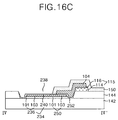
- FIGS. 16A through 16C are sectional views of the thin film transistor substrate taken along the II-II′, III-III′ and IV-IV′ lines in FIG. 15 ;
- FIGS. 17A through 17F are sectional views illustrating a method of fabricating a protective film according to another embodiment of the present invention.
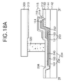
- FIGS. 18A and 18B are sectional views illustrating a fabricating method of the protective film in a method of fabricating the liquid crystal display panel employing the thin film transistor substrate of fringe field switching type according to an embodiment of the present invention.
- FIG. 2 is a plan view illustrating an exemplary a structure of a thin film transistor substrate of fringe field switching (FFS) type according to a first embodiment of the present invention
- FIGS. 3A through 3C are sectional views of the thin film transistor substrate respectively taken along the II-II′, III-III′ and IV-IV′ lines in FIG. 2 .
- FFS fringe field switching
- the FFS-type thin film transistor substrate includes a gate line 102 and a data line 104 provided on a lower substrate 142 in such a manner as to cross each other with a gate insulating film 144 between them, wherein the crossing gate lines 102 and data lines 104 define a pixel area.
- the FFS-type thin film transistor substrate includes a thin film transistor 106 connected at each crossing; a pixel electrode 118 provided at a pixel area; a common electrode 122 provided, along with the pixel electrode 118 , at the pixel area to form a fringe field; and a common line connected to the common electrode 122 .
- the thin film transistor substrate includes a gate pad 126 connected to the gate line 102 , and a data pad 134 connected to the data line 104 .
- the gate line 102 supplies a scanning signal from a gate driver (not shown) while the data line 104 supplies a video signal from a data driver (not shown).
- the gate line 102 is formed on the substrate 142 in a multiple-layer structure having at least double gate metal layers.
- the gate line 102 may have a double-layer structure in which a first conductive layer 101 includes a transparent conductive layer, and a second conductive layer 103 is formed of an opaque metal.
- the first conductive layer 101 may be formed of a transparent metal, such as ITO, TO, IZO or ITZO.
- the second conductive layer may be formed of Cu, Mo, Al, a Cu alloy, a Mo alloy or an Al alloy.
- the gate line 102 may be formed only of the second conductive layer 103 .
- the thin film transistor 106 allows a pixel signal voltage applied to the data line 104 to be charged to the pixel electrode 118 and maintained in response to a scanning signal applied to the gate line 102 .
- the thin film transistor 106 includes a gate electrode included in the gate line 102 ; a source electrode 110 connected to the data line 104 ; a drain electrode 112 positioned in opposition to the source electrode 110 and connected to the pixel electrode 118 ; an active layer 114 overlapping with the gate line 102 and having the gate insulating film 144 between them to provide a channel between the source electrode 110 and the drain electrode 112 ; and an ohmic contact layer 116 formed on the active layer 114 other than the channel portion to make an ohmic contact with the source electrode 110 and the drain electrode 112 .
- a semiconductor layer 115 including the active layer 114 and the ohmic contact layer 116 is overlapped along the data line 104 .
- the common line 120 and the common electrode 122 supply a reference voltage for driving the liquid crystal, that is, a common voltage to each pixel.
- the common line 120 includes an internal common line 120 A provided in parallel to the gate line 102 at a display area, and an external common line 120 B connected to the internal common line 120 A in an non-display area.
- the common line 120 is formed in a layered structure of first and second conductive layers 101 and 103 , similar to the gate line 102 .
- the common line 120 may be formed only of the second conductive layer 103 .
- the plate-shaped common electrode 122 is provided within the pixel area and connected to the internal common line 120 A.
- the common electrode 122 may be extended from the first conductive layer 101 of the internal common line 120 A into each pixel area and formed into a plate shape.
- the common electrode 122 may be formed from a transparent conductive layer integral to the first conductive layer 101 of the common line 120 .
- the pixel electrode 118 overlaps the common electrode 122 with the gate insulating film 144 between them at each pixel area, where they form a fringe field. Further, the pixel electrode 118 is provided on the gate insulating film 144 and is connected to the drain electrode 112 protruding from an overlapping portion. The semiconductor layer 115 may be formed such that it does not overlap between the drain electrode 112 and the pixel electrode 118 . The pixel electrode 118 overlaps with the common line 120 A.
- the pixel electrode 118 may include a first horizontal part 118 A parallel to the gate line 102 , a second horizontal part 118 B overlapping with the common line 120 A, and a plurality of vertical parts 118 C connected between the first and second horizontal parts 118 A and 118 B.
- the pixel electrode 118 forms a fringe field along with the plate-shaped common electrode 122 supplied with the common voltage.
- Liquid crystal molecules arranged in a horizontal direction between the thin film transistor array substrate and the color filter array substrate by such a fringe field are rotated due to their dielectric anisotropy. Transmittance of light through the pixel area is differentiated depending upon the extent of rotation of the liquid crystal molecules, thereby implementing a gray level scale.
- the overlapping portion between the common electrode 122 and the pixel electrode 118 is provided with a storage capacitor for stably maintaining a video signal voltage applied to the pixel electrode 118 .
- the common line 120 receives a common voltage from a common voltage source via the common pad 160 .
- the common pad 160 has a substantially similar vertical structure to the gate pad 126 .
- the common pad 160 includes a lower common pad electrode 162 extended from the common line 120 , and an upper common pad electrode 166 provided within a second contact hole 164 passing through the gate insulating film 144 to be connected to the lower common pad electrode 162 .
- the upper common pad electrode 166 along with the pixel electrode 118 , is formed from a transparent conductive layer, and makes an interface with the edge of the gate surrounding film 144 surrounding the second contact hole 164 .
- 3D illustrates an alternative data pad 134 configuration in which the data pad 134 is formed from a transparent conductive layer on the gate insulating film 144 , and is extended in such a manner to overlap with the data line 104 .
- the data line 104 protrudes from the overlapping portion between it and the semiconductor layer 115 substantially adjacent to the extending portion of the data pad 134 .
- the semiconductor layer 115 is patterned in a substantially similar manner to the gate insulating film 144 and then has an exposed portion removed upon formation of a source/drain metal pattern including the data line 104 , the source electrode 110 and the drain electrode 112 , which substantially overlay the semiconductor layer 115 . Further, upon formation of the source/drain metal pattern, the active layer 114 is exposed to define a channel of the thin film transistor 106 .
- the semiconductor layer 115 has a structure formed at a portion where a transparent conductive pattern does not exist in the channel portion between the source electrode 110 and at the drain electrode 112 and at the overlapping portion between the source/drain metal pattern and the gate insulating film 144 .
- the transparent conductive pattern is formed at a portion where the semiconductor layer 115 is removed.
- a surface layer 124 of the exposed active layer 114 is subject to a surface treatment by a plasma, so that the channel portion of the active layer 114 may be protected by the surface layer 124 oxidized by SiO 2 .
- a first mask pattern group including the gate line 102 , the lower pad electrode 128 , the common line 120 , the common electrode 122 and the lower common pad electrode 162 is formed on the lower substrate 142 by the first mask process.
- the first mask pattern group other than the common electrode 122 may have a multiple-layer structure in which at least two conductive layers are built. However, for the purpose of simplifying the explanation, there will be described only a double-layer structure having the first and second conductive layers 101 and 103 .
- the common electrode 122 has a single-layer structure of the first conductive layer 101 that is a transparent conductive layer.
- the first mask pattern group having a multiple-layer structure and single-layer structure is formed using a single mask process using a partial transmitting mask such as a diffractive exposure mask or a half tone mask.
- the opened structure is due to the offset distance between the edges of holes 170 , 130 , 164 and 138 , and the edge of the photo-resist pattern 200 A.
- the pixel electrode 118 may be in contact with or spaced from the semiconductor layer 115 enclosing the pixel hole 170 to be formed within the pixel hole 170 .
- the pixel electrode 118 overlaps with the common electrode 122 and the common line 120 A with the gate insulating film 144 between them.
- the upper gate pad electrode 132 , the common pad electrode 166 , and the data pad 134 are formed within the first to third contact holes 130 , 164 and 138 to form an interface with the gate insulating film 144 .
- the data pad 134 is formed on the gate insulating film 144 in such a manner to be in contact with or spaced from the semiconductor layer 115 , as illustrated in FIG. 8G . Accordingly, a stripper infiltration between the photo-resist pattern 200 A and the ohmic contact layer 116 facilitates the lift-off process used to remove the photo-resist pattern 200 A coated with the transparent conductive film 117 , thereby improving the efficiency of the lift-off process.
- FIG. 9A is plan view and FIGS. 9B-9D are sectional views illustrating a third mask process in an exemplary method of fabricating the FFS-type thin film transistor substrate according to an embodiment of the present invention.
- FIGS. 10A-10L are sectional views further illustrating the third mask process.
- a source/drain metal layer is formed on the lower substrate 142 , which has the semiconductor layer 115 and the transparent conductive pattern, by a deposition technique such as the sputtering.
- the source/drain metal layer may have a single layer formed of a metal material such as Mo, Ti, Cu, AlNd, Al, Cr, a Mo alloy, a Cu alloy or an Al alloy, or the source/drain metal layer may have a layered structure with at least double layers such as Al/Cr, Al/Mo, Al(Nd)/Al, Al(Nd)/Cr, Mo/Al(Nd)/Mo, Cu/Mo, Ti/Al(Nd)/Ti, Mo/Al, Mo/Ti/Al(Nd), Cu-alloy/Mo, Cu-alloy/Al, Cu-alloy/Mo-alloy, Cu-alloy/Al-alloy, Cu-alloy/Al-alloy, Al/Mo
- a third photo-resist pattern 210 including photo-resist patterns 210 A and 210 B having different thicknesses is formed on the source/drain metal layer by the photolithography using the partial transmitting mask.
- the partial transmitting mask includes a shielding part for shielding ultraviolet light, a partial transmitting part for diffracting ultraviolet light using a slit pattern or partially transmitting ultraviolet light using a phase-shifting material; and a full transmitting part for fully transmitting ultraviolet light.
- a third photo-resist pattern 210 which includes photo-resist patterns 210 A and 210 B and an aperture part, is formed by photolithography using the partial transmitting mask.
- a relatively thick photo-resist pattern 210 A is provided at a shielding area P 1 corresponding to the shielding part of the partial transmitting mask; the photo-resist pattern 210 B, which is thinner than the photo-resist pattern 210 A, is provided at a partial exposure area P 2 corresponding to the partial transmitting part, that is, at an area to be provided with the channel; and the aperture part at exposure area P 3 , which corresponds to the full transmitting part.
- the source/drain metal layer is patterned by the etching process using the third photo-resist pattern 210 as a mask to thereby provide the source/drain metal pattern including the data line 104 and the drain electrode 112 , which at this stage are integral to the source electrode 110 .
- the source/drain metal layer may be patterned by a wet etching process so that the source/drain metal pattern has an over-etched structure in comparison to the third photo-resist pattern 210 .
- the drain electrode 112 of the source/drain metal pattern protrudes from the overlapping portion between it and the semiconductor layer 115 to be connected to the pixel electrode 118 .
- the data line 104 is connected to the pixel electrode 118 in such a manner as to overlap with the data pad 134 provided within the third contact hole 138 , as illustrated in FIGS. 10A and 10C .
- the semiconductor layer 115 exposed through the third photo-resist pattern 210 is etched, so that the semiconductor layer 115 exists only in the overlapping portion between it and the second photo-resist pattern 210 .
- the exposed semiconductor layer 115 may be etched by a dry etching process having linearity using utilizing the third photo-resist pattern 210 as a mask.
- the semiconductor layer 115 exists only in the overlapping portion between it and the third photo-resist pattern 210 used to form the source/drain metal pattern, and has a structure in which the edge of the semiconductor layer 115 protrudes further than that of the source/drain metal pattern.
- the source/drain metal pattern and the semiconductor layer 115 have a step coverage in a stepwise shape, such that the semiconductor layer 115 has a slightly larger area than the source/drain metal pattern.
- the photo-resist pattern 210 A is thinned, and the photo-resist pattern 210 B illustrated in FIG. 10D is removed by an ashing process using an oxygen (O 2 ) plasma.
- O 2 oxygen
- Such an ashing process may be incorporated with a dry etching process for etching the exposed semiconductor layer 115 and performed within the same chamber.
- the surface of the active layer 114 exposed by the surface treatment process using an oxygen (O 2 ) plasma is oxidized by SiO 2 , forming surface layer 128 .
- the active layer 114 defining the channel of the thin film transistor 106 can be protected by the surface layer 124 oxidized by SiO 2 .
- the photo-resist pattern 210 A illustrated in FIGS. 10G-10I is removed by the stripping process.
- the method of fabricating the FFS-type thin film transistor substrate according to the first embodiment of the present invention can reduce the number of processes by using the exemplary three-round mask process.
- FIG. 11 is a plan view illustrating a portion of a FFS-type thin film transistor substrate according to a second embodiment of the present invention
- FIGS. 12A-12C are sectional views of the thin film transistor substrate respectively taken along the II-II′, III-III′ and IV-IV′ lines in FIG. 11 .
- the thin film transistor substrate illustrated in FIG. 11 and FIGS. 12A-12C has substantially similar elements as the thin film transistor substrate illustrated in FIGS. 2 and 3 A- 3 D, except that a data pad 234 has a vertical structure substantially identical to the gate pad 126 .
- the data pad 234 further includes a contact electrode 252 for connecting a data link 250 extended from the data pad 234 to the data line 104 . Therefore, an explanation regarding the substantially similar elements will be omitted.
- the data pad 234 includes a lower data pad electrode 236 disposed on the substrate 142 , and an upper data pad electrode 240 disposed within a third contact hole 238 passing through the gate insulating film 144 to expose the lower data pad electrode 236 so that it can be connected to the lower data pad electrode 236 in a manner similar to that of the gate pad 126 .
- the data link 250 is extended from the lower electrode 236 of the data pad 234 in such a manner as to overlap with the data line 104 and is exposed through a fourth contact hole 254 passing through the gate insulating film 144 .
- the data link 250 is connected, via the contact electrode 252 provided within the fourth contact hole 254 , to the data line 104 .
- the lower data pad electrode 236 and the data link 250 are formed in the first mask process.
- the third and fourth contact holes 238 and 254 are formed by the second mask process.
- the upper data pad electrode 240 and the contact electrode 252 are formed within the third and fourth contact holes 238 and 254 , respectively.
- the upper data pad electrode 240 and the contact electrode 252 form an interface with the edge of the gate insulating film 144 enclosing the second and third contact holes 238 and 254 .
- the data line 104 is positioned within an area sealed by the sealant so that it can be protected by the alignment film coated on it or the liquid crystal formed in the sealed area.
- the contact electrode 252 for connecting the data line 104 to the data link 250 is located within the sealed area.
- FIG. 13 is a plan view illustrating a portion of a FFS-type thin film transistor substrate according to a third embodiment of the present invention
- FIGS. 14A-14C are sectional views of the thin film transistor substrate respectively taken along the II-II′, III-III′ and IV-IV′ lines in FIG. 13 .
- the thin film transistor substrate illustrated in FIGS. 13 and 14 A- 14 C has substantially similar elements as the thin film transistor substrate illustrated in FIGS. 11 and 12 A- 12 C, except that the upper data pad electrode 240 is integral to the contact electrode 252 within the third contact hole 238 extended along the data link 250 . Accordingly, an explanation regarding similar elements will be omitted.
- the third contact hole 238 of the data pad 234 is extended along the data link 250 in such a manner as to overlap with the data line 104 .
- the upper data pad electrode 240 and the contact electrode 252 are formed in an integral structure within the second contact hole 238 to be connected to the data line 104 .
- the upper data pad electrode 240 and the contact electrode 252 form an interface with the edge of the gate insulating film 144 enclosing the third contact hole 238 .
- the thin film transistor substrate illustrated in FIGS. 15 and 16 A- 16 C has substantially similar elements as the thin film transistor substrate illustrated in FIGS. 13 and 14 A- 14 C, except that it further includes a protective film 150 provided at the remaining array area other than a pad area at which the gate pad 126 and a data pad 234 are positioned. Therefore, an explanation regarding similar elements will be omitted.
- the protective film 150 is formed on the substrate 142 with the source/drain metal pattern in such a manner as to be opened at the pad area where the gate pad 126 and the data pad 134 are provided.
- the protective film 150 is formed from an inorganic insulating film like the gate insulating film 144 .
- the protective film 150 may be formed of an acrylic organic compound, BCB (benzocyclobutene) or PFCB (perfluorocyclobutane), etc.
- the protective film 150 may be formed in the fourth mask process, or by a rubber stamp printing system like that used to form the alignment film into the uppermost layer. Further, the protective film 150 may be entirely formed on the substrate 142 and then opened at the pad area by the etching process using the alignment film as a mask, or by the etching process using the color filter substrate as a mask after joining the substrate 142 to the color filter substrate.
- the protective film 150 is entirely formed on the substrate 142 provided with the source/drain metal pattern.
- the protective film 150 is formed by a PECVD process, a, spin coating or a spinless coating, etc. Further, the protective film 150 is patterned by the photolithography and the etching process using a fourth mask to be opened at the pad area.
- the protective film 150 may be printed only at the remaining array area other than the pad area by a rubber stamp printing technique that includes a method of forming the alignment film to be provided thereon, and is thereby opened at the pad area.
- the protective film 150 may be formed by aligning a rubber mask on the substrate 142 provided with the source/drain metal pattern and then printing an insulating material only at an array area other than the pad area by the rubber stamp printing technique.
- the protective film 150 may be opened at the pad area by an etching process using the alignment film provided thereon.
- the protective film 150 is entirely formed on the substrate 142 , and the alignment film 152 is formed on the protective film 150 by the rubber stamp printing method.
- the protective film 150 is opened at the pad area by the etching process using the alignment film 152 as a mask.
- the protective film 150 may be opened at the pad area by the etching process using the color filter substrate as a mask.
- the thin film transistor substrate provided with the protective film 150 and having the lower alignment film 312 provided on thereon is joined to the color filter substrate 300 provided with the upper alignment film 310 by the sealant 320 .
- the protective film 150 is opened at the pad area by the etching process using the color filter substrate 300 as a mask.
- the protective film 150 may be opened at the pad area by the etching process using the plasma, or may be opened at the pad area by a dipping technique of dipping the liquid crystal display panel in which the thin film transistor substrate is joined to the color filter substrate 300 into an etching vessel filled with an etchant.
- a single-layer common electrode structure of is formed, along with a multiple-layer first mask pattern group, with the aid of the first partial transmitting mask.
- the semiconductor layer and the gate insulating film are simultaneously patterned by a single of mask process using the second partial transmitting mask to provide a plurality of holes having a different depth and to provide the transparent conductive pattern within the plurality of holes by a lift-off process of the photo-resist pattern used in the mask process.
- the semiconductor layer patterned simultaneously with the gate insulating film is again patterned upon formation of the source/drain metal pattern to remove the exposed portion thereof, and the active layer between the source electrode and the drain electrode is exposed to define the channel of the thin film transistor.
- the semiconductor layer substantially exists only in the channel of the thin film transistor and the overlapping portion between the source/drain metal pattern and the gate insulating film.
- the protective film having an opened pad area is further provided by the printing technique, the fourth mask process, the etching process using the alignment film as a mask, or the etching process using the color filter substrate as a mask, etc.
- the method of fabricating the FFS-type thin film transistor according to the present invention can be simplified by the three-round mask process, or the four-round mask process so that it becomes possible to reduce the material cost and the equipment investment cost, etc. as well as to improve the productivity.
Landscapes
- Physics & Mathematics (AREA)
- Nonlinear Science (AREA)
- Mathematical Physics (AREA)
- Chemical & Material Sciences (AREA)
- Crystallography & Structural Chemistry (AREA)
- General Physics & Mathematics (AREA)
- Optics & Photonics (AREA)
- Engineering & Computer Science (AREA)
- Microelectronics & Electronic Packaging (AREA)
- Geometry (AREA)
- Liquid Crystal (AREA)
- Devices For Indicating Variable Information By Combining Individual Elements (AREA)
Abstract
Description
Claims (10)
Priority Applications (1)
| Application Number | Priority Date | Filing Date | Title |
|---|---|---|---|
| US12/789,067 US8189162B2 (en) | 2004-12-31 | 2010-05-27 | Liquid crystal display device and fabricating method thereof |
Applications Claiming Priority (3)
| Application Number | Priority Date | Filing Date | Title |
|---|---|---|---|
| KR10-2004-0118603 | 2004-12-31 | ||
| KR1020040118603A KR101125254B1 (en) | 2004-12-31 | 2004-12-31 | Thin Film Transistor Substrate of Fringe Field Switching Type And Fabricating Method Thereof, Liquid Crystal Display Panel Using The Same And Fabricating Method Thereof |
| KR2004-0118603 | 2004-12-31 |
Related Child Applications (1)
| Application Number | Title | Priority Date | Filing Date |
|---|---|---|---|
| US12/789,067 Division US8189162B2 (en) | 2004-12-31 | 2010-05-27 | Liquid crystal display device and fabricating method thereof |
Publications (2)
| Publication Number | Publication Date |
|---|---|
| US20060146245A1 US20060146245A1 (en) | 2006-07-06 |
| US7760276B2 true US7760276B2 (en) | 2010-07-20 |
Family
ID=36639974
Family Applications (2)
| Application Number | Title | Priority Date | Filing Date |
|---|---|---|---|
| US11/169,571 Expired - Lifetime US7760276B2 (en) | 2004-12-31 | 2005-06-30 | Liquid crystal display device and fabricating method thereof |
| US12/789,067 Expired - Lifetime US8189162B2 (en) | 2004-12-31 | 2010-05-27 | Liquid crystal display device and fabricating method thereof |
Family Applications After (1)
| Application Number | Title | Priority Date | Filing Date |
|---|---|---|---|
| US12/789,067 Expired - Lifetime US8189162B2 (en) | 2004-12-31 | 2010-05-27 | Liquid crystal display device and fabricating method thereof |
Country Status (4)
| Country | Link |
|---|---|
| US (2) | US7760276B2 (en) |
| JP (1) | JP4477557B2 (en) |
| KR (1) | KR101125254B1 (en) |
| CN (1) | CN100485500C (en) |
Cited By (3)
| Publication number | Priority date | Publication date | Assignee | Title |
|---|---|---|---|---|
| US20010013915A1 (en) * | 1999-12-16 | 2001-08-16 | In-Duk Song | In-plane switching LCD panel |
| US20140183519A1 (en) * | 2012-03-05 | 2014-07-03 | Boe Technology Group Co. Ltd. | Thin film transistor array substrate, method for manufacturing the same and electronic device |
| US12089442B2 (en) | 2021-01-18 | 2024-09-10 | Samsung Display Co., Ltd. | Display device |
Families Citing this family (43)
| Publication number | Priority date | Publication date | Assignee | Title |
|---|---|---|---|---|
| KR20060079040A (en) * | 2004-12-31 | 2006-07-05 | 엘지.필립스 엘시디 주식회사 | Fringe-field switching type thin film transistor substrate and its manufacturing method |
| KR100878433B1 (en) * | 2005-05-18 | 2009-01-13 | 삼성전기주식회사 | Method for manufacturing ohmic contact layer of light emitting device and method for manufacturing light emitting device using same |
| TWI276902B (en) * | 2005-12-16 | 2007-03-21 | Innolux Display Corp | Liquid crystal display device |
| KR100978260B1 (en) * | 2005-12-27 | 2010-08-26 | 엘지디스플레이 주식회사 | LCD and its manufacturing method |
| KR101389219B1 (en) * | 2006-12-29 | 2014-04-24 | 엘지디스플레이 주식회사 | Liquid Crystal Display Panel and Manufacturing Method thereof |
| TW200828593A (en) * | 2006-12-29 | 2008-07-01 | Innolux Display Corp | TFT substrate and method of fabricating the same |
| JP5090745B2 (en) * | 2007-01-17 | 2012-12-05 | 株式会社ジャパンディスプレイイースト | Display device and manufacturing method of display device |
| KR100836472B1 (en) | 2007-03-22 | 2008-06-09 | 삼성에스디아이 주식회사 | Semiconductor device and manufacturing method |
| KR101350430B1 (en) * | 2007-04-02 | 2014-01-14 | 엘지디스플레이 주식회사 | An array substrate for IPS-LCD with color-filter on array |
| JP2008281799A (en) * | 2007-05-11 | 2008-11-20 | Ulvac Japan Ltd | Method of manufacturing liquid crystal display device |
| JP4496237B2 (en) * | 2007-05-14 | 2010-07-07 | 株式会社 日立ディスプレイズ | Liquid crystal display |
| CN101373299B (en) * | 2007-08-21 | 2010-11-10 | 北京京东方光电科技有限公司 | FFS thin-film transistor LCD device pixel structure and manufacturing method thereof |
| TWI341033B (en) * | 2007-10-31 | 2011-04-21 | Au Optronics Corp | Pixel structure and method for manufacturing the same |
| CN100590854C (en) * | 2007-11-08 | 2010-02-17 | 友达光电股份有限公司 | Pixel structure and manufacturing method thereof |
| CN101216642B (en) * | 2008-01-08 | 2011-04-06 | 京东方科技集团股份有限公司 | Flat-panel display lead wire structure |
| JP4956461B2 (en) * | 2008-02-20 | 2012-06-20 | 株式会社 日立ディスプレイズ | Liquid crystal display device and manufacturing method thereof |
| JP4618337B2 (en) * | 2008-06-17 | 2011-01-26 | ソニー株式会社 | Display device and manufacturing method thereof, and semiconductor device and manufacturing method thereof |
| KR101298547B1 (en) * | 2008-08-07 | 2013-08-22 | 엘지디스플레이 주식회사 | Array substrate for in-plane swithing mode LCD and method for fabricating the same |
| KR101503310B1 (en) * | 2008-09-17 | 2015-03-17 | 엘지디스플레이 주식회사 | Manufacturing method of thin film transistor |
| CN101685229B (en) * | 2008-09-25 | 2012-02-29 | 北京京东方光电科技有限公司 | Method for manufacturing liquid crystal display array substrate |
| TWI373680B (en) * | 2008-10-06 | 2012-10-01 | Au Optronics Corp | Fabricating method of pixel structure |
| TWI383232B (en) * | 2009-03-19 | 2013-01-21 | Au Optronics Corp | Thin film transistor array substrate |
| TW201037439A (en) | 2009-04-14 | 2010-10-16 | Hannstar Display Corp | Array substrate for FFS type LCD panel and method for manufacturing the same |
| CN101989016B (en) * | 2009-07-30 | 2013-03-13 | 瀚宇彩晶股份有限公司 | Array substrate for fringe electric field switching liquid crystal display panel and manufacturing method thereof |
| KR101630323B1 (en) * | 2009-09-08 | 2016-06-15 | 엘지디스플레이 주식회사 | Thin film transistor of liquid crystal display and method for fabricating the same |
| CN102148195B (en) * | 2010-04-26 | 2013-05-01 | 北京京东方光电科技有限公司 | TFT-LCD (thin film transistor-liquid crystal display) array substrate and manufacturing method thereof |
| KR101294237B1 (en) | 2010-10-07 | 2013-08-07 | 엘지디스플레이 주식회사 | Array substrate for fringe field switching mode liquid crystal display device and method of fabricating the same |
| JP2012118199A (en) * | 2010-11-30 | 2012-06-21 | Panasonic Liquid Crystal Display Co Ltd | Liquid crystal panel, liquid crystal display device, and manufacturing method thereof |
| KR101877448B1 (en) * | 2011-06-30 | 2018-07-12 | 엘지디스플레이 주식회사 | Array substrate for fringe field switching mode liquid crystal display device and method of fabricating the same |
| JP5604457B2 (en) | 2012-01-26 | 2014-10-08 | 株式会社ジャパンディスプレイ | Liquid crystal display |
| CN102544029A (en) * | 2012-02-07 | 2012-07-04 | 深圳市华星光电技术有限公司 | Thin film transistor array substrate and manufacturing method thereof |
| CN102610564B (en) * | 2012-02-07 | 2014-06-25 | 深圳市华星光电技术有限公司 | Method for manufacturing TFT array substrate |
| CN102723308B (en) * | 2012-06-08 | 2014-09-24 | 京东方科技集团股份有限公司 | Array substrate, manufacturing method thereof and display device |
| KR101987320B1 (en) * | 2012-12-31 | 2019-06-11 | 삼성디스플레이 주식회사 | Display device |
| KR20140095797A (en) | 2013-01-25 | 2014-08-04 | 삼성디스플레이 주식회사 | Thin film transistor array panel and manufacturing method thereof |
| CN103236419B (en) * | 2013-04-26 | 2014-12-17 | 京东方科技集团股份有限公司 | Preparation method of array substrate, array substrate and display device |
| KR20160090962A (en) * | 2015-01-22 | 2016-08-02 | 삼성디스플레이 주식회사 | Liquid crystal display and manufacturing method thereof |
| CN105137672B (en) * | 2015-08-10 | 2018-11-30 | 深圳市华星光电技术有限公司 | Array substrate and its manufacturing method |
| CN105140181A (en) * | 2015-09-21 | 2015-12-09 | 京东方科技集团股份有限公司 | TFT array substrate manufacturing method, TFT array substrate and display apparatus |
| CN108873509A (en) * | 2017-05-08 | 2018-11-23 | 中华映管股份有限公司 | Method for forming pixel structure |
| CN107845644B (en) * | 2017-09-27 | 2021-01-26 | 京东方科技集团股份有限公司 | Array substrate, preparation method thereof and display device |
| CN109545086B (en) * | 2018-11-29 | 2024-08-09 | 华映科技(集团)股份有限公司 | Manufacturing method of array substrate, array substrate and display panel |
| CN111653201B (en) * | 2020-06-30 | 2022-03-08 | 武汉天马微电子有限公司 | Display panel and display device |
Citations (76)
| Publication number | Priority date | Publication date | Assignee | Title |
|---|---|---|---|---|
| US4542960A (en) | 1982-06-30 | 1985-09-24 | International Business Machines Corporation | Fringe-field switched storage-effect liquid crystal display devices |
| US5162933A (en) | 1990-05-16 | 1992-11-10 | Nippon Telegraph And Telephone Corporation | Active matrix structure for liquid crystal display elements wherein each of the gate/data lines includes at least a molybdenum-base alloy layer containing 0.5 to 10 wt. % of chromium |
| US5317433A (en) | 1991-12-02 | 1994-05-31 | Canon Kabushiki Kaisha | Image display device with a transistor on one side of insulating layer and liquid crystal on the other side |
| US5339181A (en) | 1991-09-05 | 1994-08-16 | Samsung Electronics Co., Ltd. | Liquid crystal display comprising a storage capacitor including the closed-ended electrode for providing a current bath for circumventing break |
| US5462887A (en) | 1993-11-22 | 1995-10-31 | Ernst Luder | Process for making a matrix of thin layer transistors with memory capacitors |
| US5668379A (en) | 1994-07-27 | 1997-09-16 | Hitachi, Ltd. | Active matrix crystal display apparatus using thin film transistor |
| CN1170196A (en) | 1996-06-10 | 1998-01-14 | 索尼株式会社 | Photomagnetic recording medium and film |
| US5731856A (en) | 1995-12-30 | 1998-03-24 | Samsung Electronics Co., Ltd. | Methods for forming liquid crystal displays including thin film transistors and gate pads having a particular structure |
| US5771083A (en) | 1995-10-16 | 1998-06-23 | Sharp Kabushiki Kaisha | Active matrix substrate and liquid crystal display device |
| US5793460A (en) | 1995-08-22 | 1998-08-11 | Lg Electronics Inc. | Liquid crystal display device and method for manufacturing the same |
| US5847781A (en) | 1995-07-25 | 1998-12-08 | Hitachi, Ltd. | Liquid crystal display device comprises a light-blocking layer and a plurality of data lines which have a width that is larger than the width of a semiconductor layer |
| US5959708A (en) | 1996-06-21 | 1999-09-28 | Hyundai Electronics Industries Co., Ltd. | Liquid crystal display having a conductive high molecular film for preventing the fringe field in the in-plane switching mode |
| US5999236A (en) * | 1996-11-18 | 1999-12-07 | Hitachi, Ltd. | Active-matrix liquid crystal display unit in which gate and/or data lines are made of Cr containing Ne-atoms |
| JP2000002886A (en) | 1998-06-16 | 2000-01-07 | Mitsubishi Electric Corp | Manufacturing method of liquid crystal display device |
| US6034757A (en) * | 1995-10-12 | 2000-03-07 | Hitachi, Ltd. | In-plane field type liquid crystal display device comprising a structure which is prevented from charging electricity |
| JP2000206550A (en) | 1999-01-13 | 2000-07-28 | Hitachi Ltd | Liquid crystal display |
| JP2000214487A (en) | 1999-01-25 | 2000-08-04 | Hitachi Ltd | Liquid crystal display |
| JP2000314897A (en) | 1999-05-06 | 2000-11-14 | Hitachi Ltd | Liquid crystal display |
| US6215542B1 (en) | 1997-06-27 | 2001-04-10 | Hyundai Electronics Industries Co., Ltd. | Liquid crystal display with improved viewing angle and transmittance |
| CN1290952A (en) | 1999-09-30 | 2001-04-11 | 电灯专利信托有限公司 | Starter for fluorescent lamp |
| CN1290922A (en) | 1999-09-30 | 2001-04-11 | 三星电子株式会社 | Film transistor array panel for liquid crystal display and its producing method |
| US6233034B1 (en) | 1997-12-29 | 2001-05-15 | Hyundai Electronics Industries Co., Ltd. | Liquid crystal display and fabrication method |
| US20010005238A1 (en) | 1999-12-24 | 2001-06-28 | Yun Suk Shin | Method for manufacturing fringe field switching mode liquid crystal display device |
| US20010005251A1 (en) | 1999-12-22 | 2001-06-28 | Hyang Yul Kim | Fringe field switching mode LCD |
| US20010005597A1 (en) | 1999-12-22 | 2001-06-28 | Shin Jae Hak | Method for manufacturing fringe field switching mode liquid crystal display device |
| US6256081B1 (en) | 1998-05-29 | 2001-07-03 | Hyundai Electronics Industries Co., Ltd. | LCD of high aperture ratio and high transmittance preventing color shift having transparent pixel and counter electrodes producing oblique electric fields |
| US20010006765A1 (en) | 1999-12-29 | 2001-07-05 | Lee Seok Lyul | Method for manufacturing TFT LCD device |
| JP2001183685A (en) | 1999-12-27 | 2001-07-06 | Hitachi Ltd | Liquid crystal display |
| US20010007779A1 (en) * | 1999-12-22 | 2001-07-12 | Kyung Ha Lee | Method for manufacturing fringe field switching mode liquid crystal display device |
| US6281953B1 (en) | 1998-08-24 | 2001-08-28 | Hyundai Electronics Industries Co., Ltd. | Liquid crystal display having high aperture ratio and high transmittance and method of manufacturing the same |
| US6285428B1 (en) | 1997-04-18 | 2001-09-04 | Hyundai Electronics Industries Co., Ltd. | IPS LCD having molecules remained parallel with electric fields applied |
| US20010038370A1 (en) | 2000-03-28 | 2001-11-08 | Yeung Steve Wai Leung | Driving scheme for liquid crystal displays |
| US6319760B1 (en) | 1998-10-28 | 2001-11-20 | Hyundai Electronics Industries Co., Ltd. | Manufacturing method of liquid crystal display having high aperture ratio and high transmittance |
| US20010048501A1 (en) | 2000-06-01 | 2001-12-06 | Kim Hyang Yul | Fringe field switching mode liquid crystal display |
| US20010048500A1 (en) | 2000-05-31 | 2001-12-06 | Lim Kyu Hwan | Fringe field switching mode liquid crystal display |
| US20020008828A1 (en) | 2000-06-29 | 2002-01-24 | Park Chi Hyuck | Fringe field switching mode LCD |
| US6351300B1 (en) | 1998-08-24 | 2002-02-26 | Hyundai Display Technology Inc. | Reflective LCD having high transmittance and method for manufacturing the same |
| US6362032B1 (en) | 1999-04-23 | 2002-03-26 | Hyundai Display Technology Inc. | Method for manufacturing fringe field switching mode liquid crystal display |
| US6362858B1 (en) | 1998-12-16 | 2002-03-26 | Hyundai Display Technology, Inc. | Method of manufacturing liquid crystal display device |
| US20020041354A1 (en) | 2000-10-10 | 2002-04-11 | Noh Jeong Dong | Fringe field switching mode LCD |
| US6388726B1 (en) | 1998-10-29 | 2002-05-14 | Hyundai Display Technology Inc. | Method of manufacturing liquid crystal display device |
| US20020067454A1 (en) | 2000-12-05 | 2002-06-06 | Seung Ho Hong | Liquid crystal display device of reflective type fringe field switching mode |
| US20020067453A1 (en) | 2000-12-01 | 2002-06-06 | Kim Chul Ha | Fringe field switching mode liquid crystal display, and fabrication method therefor |
| US6404470B1 (en) | 1998-12-30 | 2002-06-11 | Hyundai Display Technology Inc. | Liquid crystal display having high aperture ratio and high transmittance |
| US20020084459A1 (en) * | 2000-12-29 | 2002-07-04 | Choi Seung Kyu | Thin film transistor substrate and fabricating method thereof |
| US20020089630A1 (en) | 2001-01-05 | 2002-07-11 | Hong-Da Liu | Multi-domain liquid crystal display having concave virtual bump structures |
| US6429918B1 (en) | 1998-10-29 | 2002-08-06 | Hyundai Display Technology Inc. | Liquid crystal display having high aperture ratio and high transmittance |
| US6429057B1 (en) * | 1998-01-10 | 2002-08-06 | Samsung Electronics Co., Ltd. | Method for manufacturing thin film transistor array panel for liquid crystal display |
| US6449026B1 (en) | 1999-06-25 | 2002-09-10 | Hyundai Display Technology Inc. | Fringe field switching liquid crystal display and method for manufacturing the same |
| US6456351B1 (en) | 1998-05-29 | 2002-09-24 | Hyundai Display Technology Inc. | Liquid crystal display having high transmittance and high aperture ratio in which an electric field in one sub-pixel is formed to make a symetry with the electric field in adjacent sub-pixel |
| US6462800B1 (en) | 1999-06-30 | 2002-10-08 | Hyundai Display Technology Inc. | Electrode contact structure for a liquid crystal display device and manufacturing method thereof |
| US20020158994A1 (en) * | 2001-04-26 | 2002-10-31 | Nec Corporation | Manufacturing method of liquid crystal display device |
| US20020163604A1 (en) | 2001-05-07 | 2002-11-07 | Kim Hyang Yul | In plane fringe field switching mode LCD realizing high screen quality |
| US20020180920A1 (en) | 2001-05-30 | 2002-12-05 | Noh Jeong Dong | Fringe field switching liquid crystal display device and method for manufacturing the same |
| US6512503B1 (en) | 1998-12-29 | 2003-01-28 | Hyundai Display Technology Inc. | Liquid crystal display |
| US20030076469A1 (en) | 2001-10-19 | 2003-04-24 | Industrial Technology Research Institute | Wide viewing angle fringe field multi-domain aligned LCD and method for fabricating |
| US6562645B2 (en) | 2000-06-29 | 2003-05-13 | Boe-Hydis Technology Co, Ltd. | Method of fabricating fringe field switching mode liquid crystal display |
| US20030098939A1 (en) | 1999-06-30 | 2003-05-29 | Min Tae Yop | Fringe field switching liquid crystal display and method for manufacturing the same |
| US6580487B1 (en) | 1999-06-29 | 2003-06-17 | Boe-Hydis Technology Co., Ltd. | Fringe field switching liquid crystal display |
| US20030117558A1 (en) | 2001-12-26 | 2003-06-26 | Kim Hyang Yul | Apparatus for fringe field switching liquid crystal display |
| US20030117559A1 (en) * | 2001-12-24 | 2003-06-26 | Ik-Soo Kim | Array substrate for IPS mode liquid crystal display device and method for fabricating the same |
| US20030160921A1 (en) * | 2002-02-25 | 2003-08-28 | Advanced Display Inc. | Liquid crystal display device and manufacturing method thereof |
| US20030197181A1 (en) * | 2002-04-17 | 2003-10-23 | Yun Hae Jin | Thin film transistor array substrate and manufacturing method thereof |
| US20030202140A1 (en) | 2002-04-24 | 2003-10-30 | Hong-Da Liu | Scattering fringe field optical-compensated reflective and transflective liquid crystal display |
| US6741311B1 (en) | 1999-06-29 | 2004-05-25 | Boe-Hydis Technology., Ltd. | Reflective type-fringe switching mode LCD having liquid crystal retardation (2n+1)λ/4 |
| CN1512253A (en) | 2002-12-30 | 2004-07-14 | Lg.������Lcd��ʽ���� | Method for manufacturing liquid crystal display device |
| US20050030451A1 (en) | 2003-08-06 | 2005-02-10 | Hong-Da Liu | Pixel for a fringe field switching reflective and transflective liquid crystal display |
| US20050046775A1 (en) | 2003-08-26 | 2005-03-03 | Kyung Ha Lee | FFS mode liquid crystal display |
| US20050062923A1 (en) | 1997-05-29 | 2005-03-24 | Lyu Jae-Jin | Liquid crystal display having wide viewing angle |
| US20050068483A1 (en) | 2003-09-26 | 2005-03-31 | Lee Kyung Ha | Fringe field switching liquid crystal display |
| US20050078246A1 (en) * | 2003-10-14 | 2005-04-14 | Lg.Philips Lcd Co., Ltd. | Liquid crystal display panel device and method of fabricating the same |
| US20050101044A1 (en) * | 2003-10-28 | 2005-05-12 | Cho Heung L. | Method for fabricating array substrate of liquid crystal display device |
| US7060541B2 (en) * | 2003-09-16 | 2006-06-13 | Industrial Technology Research Institute | Method of fabricating thin film transistor TFT array |
| US20060146217A1 (en) * | 2004-12-31 | 2006-07-06 | Ahn Byung C | Liquid crystal display device and fabricating method thereof |
| US20060146216A1 (en) * | 2004-12-31 | 2006-07-06 | Ahn Byung C | Liquid crystal display device and fabricating method thereof |
| US20060146213A1 (en) * | 2004-12-31 | 2006-07-06 | Ahn Byung C | Liquid crystal display device and fabricating method thereof |
Family Cites Families (6)
| Publication number | Priority date | Publication date | Assignee | Title |
|---|---|---|---|---|
| EP0372821B1 (en) * | 1988-11-30 | 1995-03-08 | Nec Corporation | Liquid crystal display panel with reduced pixel defects |
| KR970010774B1 (en) * | 1993-12-22 | 1997-06-30 | 엘지전자 주식회사 | Thin film transistor for liquid crystal device |
| US20030009013A1 (en) * | 1998-12-30 | 2003-01-09 | Genentech, Inc. | Secreted and transmembrane polypeptides and nucleic acids encoding the same |
| JP2001194675A (en) * | 2000-01-12 | 2001-07-19 | Hitachi Ltd | Liquid crystal display |
| JP3793915B2 (en) * | 2001-02-28 | 2006-07-05 | 株式会社日立製作所 | Liquid crystal display |
| KR100685946B1 (en) * | 2001-03-02 | 2007-02-23 | 엘지.필립스 엘시디 주식회사 | Liquid crystal display panel and manufacturing method thereof |
-
2004
- 2004-12-31 KR KR1020040118603A patent/KR101125254B1/en not_active Expired - Lifetime
-
2005
- 2005-06-30 US US11/169,571 patent/US7760276B2/en not_active Expired - Lifetime
- 2005-07-11 CN CNB2005100827458A patent/CN100485500C/en not_active Expired - Lifetime
- 2005-07-25 JP JP2005213711A patent/JP4477557B2/en not_active Expired - Lifetime
-
2010
- 2010-05-27 US US12/789,067 patent/US8189162B2/en not_active Expired - Lifetime
Patent Citations (80)
| Publication number | Priority date | Publication date | Assignee | Title |
|---|---|---|---|---|
| US4542960A (en) | 1982-06-30 | 1985-09-24 | International Business Machines Corporation | Fringe-field switched storage-effect liquid crystal display devices |
| US5162933A (en) | 1990-05-16 | 1992-11-10 | Nippon Telegraph And Telephone Corporation | Active matrix structure for liquid crystal display elements wherein each of the gate/data lines includes at least a molybdenum-base alloy layer containing 0.5 to 10 wt. % of chromium |
| US5339181A (en) | 1991-09-05 | 1994-08-16 | Samsung Electronics Co., Ltd. | Liquid crystal display comprising a storage capacitor including the closed-ended electrode for providing a current bath for circumventing break |
| US5317433A (en) | 1991-12-02 | 1994-05-31 | Canon Kabushiki Kaisha | Image display device with a transistor on one side of insulating layer and liquid crystal on the other side |
| US5462887A (en) | 1993-11-22 | 1995-10-31 | Ernst Luder | Process for making a matrix of thin layer transistors with memory capacitors |
| US5668379A (en) | 1994-07-27 | 1997-09-16 | Hitachi, Ltd. | Active matrix crystal display apparatus using thin film transistor |
| US5847781A (en) | 1995-07-25 | 1998-12-08 | Hitachi, Ltd. | Liquid crystal display device comprises a light-blocking layer and a plurality of data lines which have a width that is larger than the width of a semiconductor layer |
| US5793460A (en) | 1995-08-22 | 1998-08-11 | Lg Electronics Inc. | Liquid crystal display device and method for manufacturing the same |
| US6034757A (en) * | 1995-10-12 | 2000-03-07 | Hitachi, Ltd. | In-plane field type liquid crystal display device comprising a structure which is prevented from charging electricity |
| US5771083A (en) | 1995-10-16 | 1998-06-23 | Sharp Kabushiki Kaisha | Active matrix substrate and liquid crystal display device |
| US5731856A (en) | 1995-12-30 | 1998-03-24 | Samsung Electronics Co., Ltd. | Methods for forming liquid crystal displays including thin film transistors and gate pads having a particular structure |
| CN1170196A (en) | 1996-06-10 | 1998-01-14 | 索尼株式会社 | Photomagnetic recording medium and film |
| US5959708A (en) | 1996-06-21 | 1999-09-28 | Hyundai Electronics Industries Co., Ltd. | Liquid crystal display having a conductive high molecular film for preventing the fringe field in the in-plane switching mode |
| US5999236A (en) * | 1996-11-18 | 1999-12-07 | Hitachi, Ltd. | Active-matrix liquid crystal display unit in which gate and/or data lines are made of Cr containing Ne-atoms |
| US6285428B1 (en) | 1997-04-18 | 2001-09-04 | Hyundai Electronics Industries Co., Ltd. | IPS LCD having molecules remained parallel with electric fields applied |
| US20050062923A1 (en) | 1997-05-29 | 2005-03-24 | Lyu Jae-Jin | Liquid crystal display having wide viewing angle |
| US6215542B1 (en) | 1997-06-27 | 2001-04-10 | Hyundai Electronics Industries Co., Ltd. | Liquid crystal display with improved viewing angle and transmittance |
| US20010010576A1 (en) | 1997-12-29 | 2001-08-02 | Lee Seug Hee | Liquid crystal display and fabrication method |
| US6233034B1 (en) | 1997-12-29 | 2001-05-15 | Hyundai Electronics Industries Co., Ltd. | Liquid crystal display and fabrication method |
| US6429057B1 (en) * | 1998-01-10 | 2002-08-06 | Samsung Electronics Co., Ltd. | Method for manufacturing thin film transistor array panel for liquid crystal display |
| US6456351B1 (en) | 1998-05-29 | 2002-09-24 | Hyundai Display Technology Inc. | Liquid crystal display having high transmittance and high aperture ratio in which an electric field in one sub-pixel is formed to make a symetry with the electric field in adjacent sub-pixel |
| US6256081B1 (en) | 1998-05-29 | 2001-07-03 | Hyundai Electronics Industries Co., Ltd. | LCD of high aperture ratio and high transmittance preventing color shift having transparent pixel and counter electrodes producing oblique electric fields |
| JP2000002886A (en) | 1998-06-16 | 2000-01-07 | Mitsubishi Electric Corp | Manufacturing method of liquid crystal display device |
| US6281953B1 (en) | 1998-08-24 | 2001-08-28 | Hyundai Electronics Industries Co., Ltd. | Liquid crystal display having high aperture ratio and high transmittance and method of manufacturing the same |
| US20020044248A1 (en) | 1998-08-24 | 2002-04-18 | In Cheol Park | Reflective LCD having high transmittance and method for manufacturing the same |
| US6351300B1 (en) | 1998-08-24 | 2002-02-26 | Hyundai Display Technology Inc. | Reflective LCD having high transmittance and method for manufacturing the same |
| US6319760B1 (en) | 1998-10-28 | 2001-11-20 | Hyundai Electronics Industries Co., Ltd. | Manufacturing method of liquid crystal display having high aperture ratio and high transmittance |
| US6429918B1 (en) | 1998-10-29 | 2002-08-06 | Hyundai Display Technology Inc. | Liquid crystal display having high aperture ratio and high transmittance |
| US6388726B1 (en) | 1998-10-29 | 2002-05-14 | Hyundai Display Technology Inc. | Method of manufacturing liquid crystal display device |
| US6362858B1 (en) | 1998-12-16 | 2002-03-26 | Hyundai Display Technology, Inc. | Method of manufacturing liquid crystal display device |
| US6512503B1 (en) | 1998-12-29 | 2003-01-28 | Hyundai Display Technology Inc. | Liquid crystal display |
| US6404470B1 (en) | 1998-12-30 | 2002-06-11 | Hyundai Display Technology Inc. | Liquid crystal display having high aperture ratio and high transmittance |
| JP2000206550A (en) | 1999-01-13 | 2000-07-28 | Hitachi Ltd | Liquid crystal display |
| JP2000214487A (en) | 1999-01-25 | 2000-08-04 | Hitachi Ltd | Liquid crystal display |
| US6362032B1 (en) | 1999-04-23 | 2002-03-26 | Hyundai Display Technology Inc. | Method for manufacturing fringe field switching mode liquid crystal display |
| JP2000314897A (en) | 1999-05-06 | 2000-11-14 | Hitachi Ltd | Liquid crystal display |
| US6449026B1 (en) | 1999-06-25 | 2002-09-10 | Hyundai Display Technology Inc. | Fringe field switching liquid crystal display and method for manufacturing the same |
| US6580487B1 (en) | 1999-06-29 | 2003-06-17 | Boe-Hydis Technology Co., Ltd. | Fringe field switching liquid crystal display |
| US6741311B1 (en) | 1999-06-29 | 2004-05-25 | Boe-Hydis Technology., Ltd. | Reflective type-fringe switching mode LCD having liquid crystal retardation (2n+1)λ/4 |
| US20030098939A1 (en) | 1999-06-30 | 2003-05-29 | Min Tae Yop | Fringe field switching liquid crystal display and method for manufacturing the same |
| US6462800B1 (en) | 1999-06-30 | 2002-10-08 | Hyundai Display Technology Inc. | Electrode contact structure for a liquid crystal display device and manufacturing method thereof |
| CN1290952A (en) | 1999-09-30 | 2001-04-11 | 电灯专利信托有限公司 | Starter for fluorescent lamp |
| CN1290922A (en) | 1999-09-30 | 2001-04-11 | 三星电子株式会社 | Film transistor array panel for liquid crystal display and its producing method |
| US20010007779A1 (en) * | 1999-12-22 | 2001-07-12 | Kyung Ha Lee | Method for manufacturing fringe field switching mode liquid crystal display device |
| US20010005251A1 (en) | 1999-12-22 | 2001-06-28 | Hyang Yul Kim | Fringe field switching mode LCD |
| US20010005597A1 (en) | 1999-12-22 | 2001-06-28 | Shin Jae Hak | Method for manufacturing fringe field switching mode liquid crystal display device |
| US20010005238A1 (en) | 1999-12-24 | 2001-06-28 | Yun Suk Shin | Method for manufacturing fringe field switching mode liquid crystal display device |
| JP2001183685A (en) | 1999-12-27 | 2001-07-06 | Hitachi Ltd | Liquid crystal display |
| US20010006765A1 (en) | 1999-12-29 | 2001-07-05 | Lee Seok Lyul | Method for manufacturing TFT LCD device |
| US20010038370A1 (en) | 2000-03-28 | 2001-11-08 | Yeung Steve Wai Leung | Driving scheme for liquid crystal displays |
| US20010048500A1 (en) | 2000-05-31 | 2001-12-06 | Lim Kyu Hwan | Fringe field switching mode liquid crystal display |
| US20010048501A1 (en) | 2000-06-01 | 2001-12-06 | Kim Hyang Yul | Fringe field switching mode liquid crystal display |
| US20020008828A1 (en) | 2000-06-29 | 2002-01-24 | Park Chi Hyuck | Fringe field switching mode LCD |
| US6678027B2 (en) | 2000-06-29 | 2004-01-13 | Boe-Hydis Technology Co., Ltd. | Fringe field switching mode LCD |
| US6562645B2 (en) | 2000-06-29 | 2003-05-13 | Boe-Hydis Technology Co, Ltd. | Method of fabricating fringe field switching mode liquid crystal display |
| US20020041354A1 (en) | 2000-10-10 | 2002-04-11 | Noh Jeong Dong | Fringe field switching mode LCD |
| US20020067453A1 (en) | 2000-12-01 | 2002-06-06 | Kim Chul Ha | Fringe field switching mode liquid crystal display, and fabrication method therefor |
| US6583842B2 (en) | 2000-12-05 | 2003-06-24 | Boe-Hydis Technology Co., Ltd. | Liquid crystal display device of reflective type fringe field switching mode |
| US20020067454A1 (en) | 2000-12-05 | 2002-06-06 | Seung Ho Hong | Liquid crystal display device of reflective type fringe field switching mode |
| US20020084459A1 (en) * | 2000-12-29 | 2002-07-04 | Choi Seung Kyu | Thin film transistor substrate and fabricating method thereof |
| US20020089630A1 (en) | 2001-01-05 | 2002-07-11 | Hong-Da Liu | Multi-domain liquid crystal display having concave virtual bump structures |
| US20020158994A1 (en) * | 2001-04-26 | 2002-10-31 | Nec Corporation | Manufacturing method of liquid crystal display device |
| US20020163604A1 (en) | 2001-05-07 | 2002-11-07 | Kim Hyang Yul | In plane fringe field switching mode LCD realizing high screen quality |
| US20020180920A1 (en) | 2001-05-30 | 2002-12-05 | Noh Jeong Dong | Fringe field switching liquid crystal display device and method for manufacturing the same |
| US20030076469A1 (en) | 2001-10-19 | 2003-04-24 | Industrial Technology Research Institute | Wide viewing angle fringe field multi-domain aligned LCD and method for fabricating |
| US20030117559A1 (en) * | 2001-12-24 | 2003-06-26 | Ik-Soo Kim | Array substrate for IPS mode liquid crystal display device and method for fabricating the same |
| US20030117558A1 (en) | 2001-12-26 | 2003-06-26 | Kim Hyang Yul | Apparatus for fringe field switching liquid crystal display |
| US20030160921A1 (en) * | 2002-02-25 | 2003-08-28 | Advanced Display Inc. | Liquid crystal display device and manufacturing method thereof |
| US20030197181A1 (en) * | 2002-04-17 | 2003-10-23 | Yun Hae Jin | Thin film transistor array substrate and manufacturing method thereof |
| US20030202140A1 (en) | 2002-04-24 | 2003-10-30 | Hong-Da Liu | Scattering fringe field optical-compensated reflective and transflective liquid crystal display |
| CN1512253A (en) | 2002-12-30 | 2004-07-14 | Lg.������Lcd��ʽ���� | Method for manufacturing liquid crystal display device |
| US20050030451A1 (en) | 2003-08-06 | 2005-02-10 | Hong-Da Liu | Pixel for a fringe field switching reflective and transflective liquid crystal display |
| US20050046775A1 (en) | 2003-08-26 | 2005-03-03 | Kyung Ha Lee | FFS mode liquid crystal display |
| US7060541B2 (en) * | 2003-09-16 | 2006-06-13 | Industrial Technology Research Institute | Method of fabricating thin film transistor TFT array |
| US20050068483A1 (en) | 2003-09-26 | 2005-03-31 | Lee Kyung Ha | Fringe field switching liquid crystal display |
| US20050078246A1 (en) * | 2003-10-14 | 2005-04-14 | Lg.Philips Lcd Co., Ltd. | Liquid crystal display panel device and method of fabricating the same |
| US20050101044A1 (en) * | 2003-10-28 | 2005-05-12 | Cho Heung L. | Method for fabricating array substrate of liquid crystal display device |
| US20060146217A1 (en) * | 2004-12-31 | 2006-07-06 | Ahn Byung C | Liquid crystal display device and fabricating method thereof |
| US20060146216A1 (en) * | 2004-12-31 | 2006-07-06 | Ahn Byung C | Liquid crystal display device and fabricating method thereof |
| US20060146213A1 (en) * | 2004-12-31 | 2006-07-06 | Ahn Byung C | Liquid crystal display device and fabricating method thereof |
Cited By (5)
| Publication number | Priority date | Publication date | Assignee | Title |
|---|---|---|---|---|
| US20010013915A1 (en) * | 1999-12-16 | 2001-08-16 | In-Duk Song | In-plane switching LCD panel |
| US7916258B2 (en) * | 1999-12-16 | 2011-03-29 | Lg Display Co., Ltd. | In-plane switching LCD panel |
| US20140183519A1 (en) * | 2012-03-05 | 2014-07-03 | Boe Technology Group Co. Ltd. | Thin film transistor array substrate, method for manufacturing the same and electronic device |
| US8952387B2 (en) * | 2012-03-05 | 2015-02-10 | Boe Technology Group Co., Ltd. | Thin film transistor array substrate and method for manufacturing the same |
| US12089442B2 (en) | 2021-01-18 | 2024-09-10 | Samsung Display Co., Ltd. | Display device |
Also Published As
| Publication number | Publication date |
|---|---|
| US20100237349A1 (en) | 2010-09-23 |
| KR20060079035A (en) | 2006-07-05 |
| US20060146245A1 (en) | 2006-07-06 |
| CN100485500C (en) | 2009-05-06 |
| CN1797157A (en) | 2006-07-05 |
| KR101125254B1 (en) | 2012-03-21 |
| JP2006189775A (en) | 2006-07-20 |
| US8189162B2 (en) | 2012-05-29 |
| JP4477557B2 (en) | 2010-06-09 |
Similar Documents
| Publication | Publication Date | Title |
|---|---|---|
| US7760276B2 (en) | Liquid crystal display device and fabricating method thereof | |
| US7859639B2 (en) | Liquid crystal display device and fabricating method thereof using three mask process | |
| US7733453B2 (en) | Method of fabricating a liquid crystal display device using a three mask process and double layer electrodes | |
| US8411244B2 (en) | Liquid crystal display device and fabricating method thereof with a simplified mask process | |
| US7751021B2 (en) | Liquid crystal display and fabricating method thereof | |
| US7894032B2 (en) | Liquid crystal display device having particular structure for data line, source electrode, drain electrode and pixel electrode | |
| US7564529B2 (en) | Liquid crystal display device and fabricating method thereof | |
| US7118947B2 (en) | Thin film transistor substrate of a horizontal electric field type LCD and fabricating method thereof | |
| JP2006163407A (en) | Liquid crystal display device and manufacturing method thereof | |
| US20050110931A1 (en) | Thin film transistor substrate using horizontal electric field and fabricating method thereof | |
| US8400600B2 (en) | Liquid crystal display device and fabricating method thereof | |
| US8179510B2 (en) | Liquid crystal display device and fabricating method thereof | |
| US7679699B2 (en) | Liquid crystal display device and fabricating method thereof | |
| US7990510B2 (en) | Liquid crystal display device | |
| US20050110932A1 (en) | Thin film transistor substrate of horizontal electric field type liquid crystal display device and fabricating method thereof | |
| US7580106B2 (en) | Liquid crystal display device and fabricating method thereof |
Legal Events
| Date | Code | Title | Description |
|---|---|---|---|
| AS | Assignment |
Owner name: LG.PHILIPS LCD CO., LTD., KOREA, REPUBLIC OF Free format text: ASSIGNMENT OF ASSIGNORS INTEREST;ASSIGNORS:AHN, BYUNG CHUL;LIM, BYOUNG HO;AHN, JAE JUN;SIGNING DATES FROM 20050629 TO 20050630;REEL/FRAME:017289/0912 Owner name: LG.PHILIPS LCD CO., LTD., KOREA, REPUBLIC OF Free format text: ASSIGNMENT OF ASSIGNORS INTEREST;ASSIGNORS:AHN, BYUNG CHUL;LIM, BYOUNG HO;AHN, JAE JUN;REEL/FRAME:017289/0912;SIGNING DATES FROM 20050629 TO 20050630 |
|
| AS | Assignment |
Owner name: LG DISPLAY CO., LTD., KOREA, REPUBLIC OF Free format text: CHANGE OF NAME;ASSIGNOR:LG.PHILIPS LCD CO., LTD.;REEL/FRAME:021763/0117 Effective date: 20080304 Owner name: LG DISPLAY CO., LTD.,KOREA, REPUBLIC OF Free format text: CHANGE OF NAME;ASSIGNOR:LG.PHILIPS LCD CO., LTD.;REEL/FRAME:021763/0117 Effective date: 20080304 |
|
| FEPP | Fee payment procedure |
Free format text: PAYOR NUMBER ASSIGNED (ORIGINAL EVENT CODE: ASPN); ENTITY STATUS OF PATENT OWNER: LARGE ENTITY |
|
| STCF | Information on status: patent grant |
Free format text: PATENTED CASE |
|
| FPAY | Fee payment |
Year of fee payment: 4 |
|
| MAFP | Maintenance fee payment |
Free format text: PAYMENT OF MAINTENANCE FEE, 8TH YEAR, LARGE ENTITY (ORIGINAL EVENT CODE: M1552) Year of fee payment: 8 |
|
| MAFP | Maintenance fee payment |
Free format text: PAYMENT OF MAINTENANCE FEE, 12TH YEAR, LARGE ENTITY (ORIGINAL EVENT CODE: M1553); ENTITY STATUS OF PATENT OWNER: LARGE ENTITY Year of fee payment: 12 |