US7724755B2 - Communications apparatus - Google Patents
Communications apparatus Download PDFInfo
- Publication number
- US7724755B2 US7724755B2 US11/598,023 US59802306A US7724755B2 US 7724755 B2 US7724755 B2 US 7724755B2 US 59802306 A US59802306 A US 59802306A US 7724755 B2 US7724755 B2 US 7724755B2
- Authority
- US
- United States
- Prior art keywords
- data
- processing unit
- communications apparatus
- opposed
- application processing
- Prior art date
- Legal status (The legal status is an assumption and is not a legal conclusion. Google has not performed a legal analysis and makes no representation as to the accuracy of the status listed.)
- Expired - Fee Related, expires
Links
Images


Classifications
-
- H—ELECTRICITY
- H04—ELECTRIC COMMUNICATION TECHNIQUE
- H04L—TRANSMISSION OF DIGITAL INFORMATION, e.g. TELEGRAPHIC COMMUNICATION
- H04L67/00—Network arrangements or protocols for supporting network services or applications
- H04L67/01—Protocols
- H04L67/10—Protocols in which an application is distributed across nodes in the network
- H04L67/1001—Protocols in which an application is distributed across nodes in the network for accessing one among a plurality of replicated servers
- H04L67/1004—Server selection for load balancing
- H04L67/1008—Server selection for load balancing based on parameters of servers, e.g. available memory or workload
-
- H—ELECTRICITY
- H04—ELECTRIC COMMUNICATION TECHNIQUE
- H04L—TRANSMISSION OF DIGITAL INFORMATION, e.g. TELEGRAPHIC COMMUNICATION
- H04L67/00—Network arrangements or protocols for supporting network services or applications
- H04L67/01—Protocols
- H04L67/10—Protocols in which an application is distributed across nodes in the network
- H04L67/1001—Protocols in which an application is distributed across nodes in the network for accessing one among a plurality of replicated servers
- H04L67/1004—Server selection for load balancing
- H04L67/1012—Server selection for load balancing based on compliance of requirements or conditions with available server resources
-
- H—ELECTRICITY
- H04—ELECTRIC COMMUNICATION TECHNIQUE
- H04L—TRANSMISSION OF DIGITAL INFORMATION, e.g. TELEGRAPHIC COMMUNICATION
- H04L67/00—Network arrangements or protocols for supporting network services or applications
- H04L67/01—Protocols
- H04L67/10—Protocols in which an application is distributed across nodes in the network
- H04L67/1001—Protocols in which an application is distributed across nodes in the network for accessing one among a plurality of replicated servers
- H04L67/1029—Protocols in which an application is distributed across nodes in the network for accessing one among a plurality of replicated servers using data related to the state of servers by a load balancer
-
- H—ELECTRICITY
- H04—ELECTRIC COMMUNICATION TECHNIQUE
- H04L—TRANSMISSION OF DIGITAL INFORMATION, e.g. TELEGRAPHIC COMMUNICATION
- H04L69/00—Network arrangements, protocols or services independent of the application payload and not provided for in the other groups of this subclass
- H04L69/16—Implementation or adaptation of Internet protocol [IP], of transmission control protocol [TCP] or of user datagram protocol [UDP]
- H04L69/163—In-band adaptation of TCP data exchange; In-band control procedures
Definitions
- the present invention relates to a data communications apparatus for controlling a retransmission.
- TCP Transmission Control Protocol
- a transmitting side sets a retransmission timer each time it transmits transmission data (transmission segment). Upon detection of a timeout, the transmitting side retransmits the same transmission data. In the meantime, a receiving side checks a sequence number attached to the header of the transmission data, and issues a request to retransmit the transmission data that does not reach.
- FIG. 1 is a block diagram exemplifying a configuration of a conventional data communications system.
- An opposed communications apparatus 1201 shown in FIG. 1 is configured with an application processing unit 1201 a for making a data communication, a protocol processing unit 1201 b for enabling a communication between arbitrary computers and for assuring transmission data, and an interface 1201 c for converting an electric signal on a network into digital data and for enabling a data transmission between the computers.
- the application processing unit 1201 a is equivalent to an application layer of TCP/IP (Internet Protocol), and the protocol processing unit 1201 b is equivalent to TCP and IP layers of TCP/IP.
- the interface 1201 c is equivalent to a network interface layer of TCP/IP.
- a communications apparatus 1202 is configured with an application processing unit 1202 a , a protocol processing unit 1202 b , and an interface 1202 c .
- the opposed communications apparatus 1201 and the communications apparatus 1202 are interconnected via a communications network 1203 to make a communication.
- the communications network 1203 may be directly connected, or may be connected by a network via a plurality of apparatuses.
- FIG. 2 is a schematic showing the outline of a communication process performed in the conventional data communications system. A case where the opposed communications apparatus 1201 and the communications apparatus 1202 make a data communication is described below in correspondence with (1) through (14) shown in FIG. 2 .
- the application processing unit 1201 a transmits transmission data to the protocol processing unit 1201 b.
- the protocol processing unit 1201 b which receives the transmission data, transmits a connection request to the communications apparatus 1202 , being a transmission destination, in order to establish a connection. At this time, the connection request is transmitted to the communications apparatus 1202 via the interface 1201 c and the communications network 1203 , although this is not shown in FIG. 2 .
- the protocol processing unit 1202 b transmits a connection response to the opposed communications apparatus 1201 , being the transmitter, and establishes a connection.
- the protocol processing unit 1201 b partitions the data received from the application processing unit 1201 a into a predetermined size, and starts to sequentially transmit the partitioned data to the communications apparatus 1202 .
- the protocol processing unit 1202 b transmits a data reception response to the opposed communications apparatus 1201 each time the data is received.
- the protocol processing unit 1202 b restores the transmission data partitioned in (4), and transmits the restored data to the application processing unit 1202 a.
- the protocol processing unit 1201 b which accepts the data ⁇ from the application processing unit 1201 a , transmits the data ⁇ to the communications apparatus 1202 .
- the protocol processing unit 1202 b which receives the data ⁇ , transmits a reception response to the data ⁇ to the opposed communications apparatus 1201 which is a transmitter.
- the protocol processing unit 1202 b transmits the received data ⁇ to the application processing unit 1202 a.
- the protocol processing unit 1201 b which accepts the data ⁇ from the application processing unit 1201 a , transmits the data ⁇ to the communications apparatus 1202 .
- the protocol processing unit 1201 b transmits the data ⁇ , and activates a retransmission timer to monitor the reception response to the data ⁇ . Upon detection of a timeout, the protocol processing unit 1201 b retransmits the data ⁇ .
- the protocol processing unit 1202 b which receives the data ⁇ , transmits the reception response to the data ⁇ to the opposed communication apparatus 1201 which is the transmitter.
- the protocol processing unit 1202 b transmits the received data ⁇ to the application processing unit 1202 a.
- the application processing unit 1202 a has completed the reception of only the data ⁇ although the application processing unit 1201 a has completed the transmission of the data ⁇ and ⁇ to the communications apparatus 1202 .
- Japanese Published Unexamined Patent Application No. H11-177536 discloses a wireless data link layer error control method for preventing a throughput characteristic from degrading due to the number of unnecessary retransmissions, which grows with an increase in transmission errors caused by degradation in a line state, by monitoring the line state and suspending a retransmission control when the line state degrades below a reference value, and by restarting the retransmission control when a monitoring result restores to a more favorable value than the reference value.
- WO Patent Publication No. 2002/056631 discloses a mobile communications system, which can reduce a delay time required for a retransmission between two processing units of a layer by suppressing the missing of data and a retransmission request frame for a retransmission request between the two processing units of the layer in a base station and a mobile station, and can prevent a throughput from degrading by suppressing an occurrence of a timeout in an upper TCP.
- the present invention was developed in consideration of the above described problem, and an object thereof is to provide a communications apparatus for preventing degradation in data quality, which is caused by the missing of reception data at the time of a data communication.
- a communications apparatus is, in a state where a communication can be made with an opposed communications apparatus, a communications apparatus comprising an application processing unit for making a data communication with the opposed communications apparatus, and a protocol processing unit for transmitting/receiving data according to an instruction from the application processing unit and for assuring transmission data by retransmitting the data to the opposed communications apparatus if a reception response to the data transmitted to the opposed communications apparatus is not received during a predetermined duration.
- the protocol processing unit comprises a first data notifying unit for transmitting a reception response to data upon receipt of the data from the opposed communications apparatus and for passing the data to the application processing unit, and a second data notifying unit for passing data to the application processing unit upon receipt of the data from the opposed communications apparatus and for transmitting a reception response to the data according to an instruction from the application processing unit.
- the application processing unit comprises a load monitor processing unit for monitoring a load of a transmission/reception process based on the data passed from the first data notifying unit and for switching from the first data notifying unit to the second data notifying unit if the load exceeds a predetermined load, and a reception response processing unit for issuing to the second data notifying unit an instruction to transmit a reception response to the passed data when the data is passed from the second data notifying unit.
- the load monitor processing unit monitors the load of the transmission/reception process, and switches from the first data notifying unit to the second data notifying unit if the load exceeds a predetermined load.
- reception response processing unit (application processing unit) issues to the second data notifying unit (protocol processing unit) the instruction to transmit a reception response, and the second data notifying unit, which receives the instruction, transmits a reception response.
- the application processing unit cannot receive data, by way of example, for a reason that the data transmitted from the protocol processing unit to the application processing unit is destroyed, the protocol processing unit does not transmit a reception response. Therefore, the transmitting side detects a timeout and retransmits the destroyed data, whereby degradation in data quality, which is caused by the missing of reception data, can be prevented.
- the communications apparatus may be a communications apparatus comprising an application processing unit for making a data communication with an opposed communications apparatus connected to be communicable, and a protocol processing unit for transmitting/receiving data according to an instruction from the application processing unit and for assuring transmission data by retransmitting the data to the opposed communications apparatus if a reception response to the data transmitted to the opposed communications apparatus is not received during a predetermined duration
- the protocol processing unit comprises a first data notifying unit for transmitting a reception response to data upon receipt of the data from the opposed communications apparatus and for passing the data to the application processing unit, and a second data notifying unit for destroying the data under a predetermined rule upon receipt of the data from the opposed communications apparatus
- the application processing unit comprises a load monitor processing unit for monitoring a load of a transmission/reception process based on the data passed from the first data notifying unit and for switching from the first data notifying unit to the second data notifying unit if the load exceeds a predetermined load.
- the load monitor processing unit monitors the load of the transmission/reception process, and switches from the first data notifying unit to the second data notifying unit if the load exceeds a predetermined load. Then, the second data notifying unit destroys the reception data under a predetermined rule. When the reception data is destroyed, the communications apparatus on the transmitting side detects a timeout, and retransmits the destroyed data.
- a communications apparatus for preventing degradation in data quality, which is caused by the missing of reception data at the time of a data communication can be provided.
- FIG. 1 is a block diagram exemplifying a configuration of a conventional data communications system
- FIG. 2 is a schematic showing the outline of a communication process performed in the conventional data communications system
- FIG. 3 is a block diagram explaining the outline of a communications apparatus according to a preferred embodiment of the present invention.
- FIG. 4 is a block diagram exemplifying a configuration of a data communications system according to the preferred embodiment of the present invention.
- FIG. 5 is a schematic showing the outline of a communication process performed in the data communications system according to the preferred embodiment of the present invention.
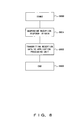
- FIG. 6 is a flowchart showing a process performed by an application processing unit in the communications apparatus according to the preferred embodiment of the present invention.
- FIG. 7 is a flowchart showing a process performed by a protocol processing unit in the communications apparatus according to the preferred embodiment of the present invention.
- FIG. 8 is a flowchart showing a process performed by the protocol processing unit in data reception response upper return mode according to the preferred embodiment of the present invention.
- FIG. 9 is a flowchart showing a process performed by the protocol processing unit in transmission performance restriction mode according to the preferred embodiment of the present invention.
- FIG. 10 is a flowchart showing a process performed by the protocol processing unit in particular signal destruction mode according to the preferred embodiment of the present invention.
- FIG. 11 is a flowchart showing a process performed by the protocol processing unit in particular signal permission mode according to the preferred embodiment of the present invention.
- FIG. 12 is a block diagram exemplifying a modification of the configuration of the communications apparatus according to the preferred embodiment of the present invention.
- FIG. 13 is a block diagram exemplifying a modification of the configuration of the communications apparatus according to the preferred embodiment of the present invention.
- FIG. 3 is a block diagram explaining the outline of a communications apparatus 10 according to a preferred embodiment of the present invention.
- the communications apparatus 10 shown in FIG. 3 is a communications apparatus at least comprising an application processing unit 11 for making a data communication, and a protocol processing unit 12 for performing a data process under a predetermined protocol.
- the application processing unit 11 provides a data communications service such as an HTTP (HyperText Transfer Protocol) communication, an FTP (File Transfer Protocol) communication, or the like.
- HTTP HyperText Transfer Protocol
- FTP File Transfer Protocol
- the application processing unit 11 comprises a load monitor processing unit 11 a for monitoring a load imposed at the time of a reception data process, and a reception response processing unit 11 b for issuing a reception response instruction to the protocol processing unit 12 .
- the load monitor processing unit 11 a continually monitors the load imposed to process data received from the protocol processing unit 12 . If the load exceeds a predetermined value, the load monitor processing unit 11 a issues to the protocol processing unit 12 an instruction to switch from the first data notifying unit 12 a to the second data notifying unit 12 b.
- the reception response processing unit 11 b issues to the second data notifying unit 12 b an instruction to transmit a reception response to the reception data.
- the protocol processing unit 12 performs a protocol process, for example, under TCP/IP.
- the protocol processing unit 12 comprises the first data notifying unit 12 a for transmitting a reception response upon receipt of data from an opposed communications apparatus and for transmitting the received data to the application processing unit 11 , and the second data notifying unit 12 b for transmitting received data to the application processing unit 11 upon receipt of the data from the opposed communications apparatus and for transmitting a reception response according to an instruction from the reception response processing unit 11 b.
- the first data notifying unit 12 a transmits a reception response to the opposed communications apparatus, and also transmits the received data to the application processing unit 11 .
- the load monitor processing unit 11 a Upon receipt of the data from the protocol processing unit 12 , the load monitor processing unit 11 a monitors whether or not a load imposed at the time of a data reception process in the application processing unit 22 a exceeds a predetermined value. If the load exceeds the predetermined value, switching is made from the first data notifying unit 12 a to the second data notifying unit 12 b in the protocol processing unit 12 , and the operations of the reception response processing unit 11 b are started. Namely, a control mode is turned on.
- the second data notifying unit 12 b transmits the reception data to the application processing unit 11 .
- the reception response processing unit 11 b issues a reception response instruction to the second data notifying unit 12 b .
- the second data notifying unit 12 b which receives the reception response instruction, transmits a reception response to the opposed communications apparatus.
- FIG. 4 is a block diagram exemplifying a configuration of a data communications system according to the preferred embodiment of the present invention.
- a normal opposed communications apparatus 21 using a protocol such as TCP, etc.
- the communications apparatus 22 are interconnected via a communications network 23 .
- the opposed communications apparatus 21 is a normal communications apparatus comprising an application processing unit 21 a for making a data communication, a protocol processing unit 21 b for enabling a communication between arbitrary computers and for assuring transmission data, and an interface 21 c for converting an electric signal on the network into electronic data and for enabling a data transmission between the computers.
- the application processing unit 21 a is equivalent to an application layer of TCP/IP
- the protocol processing unit 21 b is equivalent to TCP and IP layers of TCP/IP
- the interface 21 c is equivalent to a network interface layer of TCP/IP.
- the communications apparatus 22 comprises an application processing unit 22 a for making a data communication, a protocol processing unit 22 b for enabling a communication between arbitrary computers and for assuring transmission data, and an interface 22 c for converting an electric signal on the network into electronic data and for enabling a data transmission between the computers, similar to the opposed communications apparatus 21 .
- the application processing unit 22 a comprises a threshold value managing unit 22 d , a retransmission protocol controlling unit 22 e and a protocol management table 22 f in addition to the above described capabilities.
- the threshold value managing unit 22 d monitors a load by measuring the load imposed at the time of a data communication in the application processing unit 22 a . If the measured load exceeds a predetermined threshold value as a result of a comparison made between the measured load and the threshold value, the threshold value managing unit 22 d determines that a control for a retransmission protocol is required because the load becomes heavy.
- a message amount (data size) received per unit time is used as the “load imposed at the time of a data communication”.
- the load is not limited to the message amount. Information expected to represent the “load imposed at the time of a data communication” may be used on demand.
- the retransmission protocol controlling unit 22 e controls the retransmission capability of the protocol processing unit 22 b.
- the protocol management table 22 f is a management table used to manage a communications apparatus, for which a retransmission process is to be performed.
- the IP address and the port number of the communications apparatus, which is making a communication are stored in the protocol management table 22 f.
- FIG. 4 shows the case where the normal opposed communications apparatus 21 is used on the transmitting side, and the communications apparatus 22 according to this preferred embodiment is used on the receiving side.
- communications apparatuses 22 may be used as both of the apparatuses on the transmitting and the receiving sides as a matter of course.
- FIG. 5 is a schematic showing the outline of a communication process performed in the data communications system according to the preferred embodiment of the present invention. A case where the opposed communications apparatus 21 and the communications apparatus 22 make a data communication is described below in correspondence with (1) through (23) shown in FIG. 5 .
- the application processing unit 21 a transmits transmission data to the protocol processing unit 21 b.
- the protocol processing unit 21 b which receives the transmission data, transmits a connection request signal to the communications apparatus 22 which is a transmission destination in order to establish a connection. At this time, the connection request signal is transmitted to the communications apparatus 22 via the interface 21 c and the communications network 23 , although both are not shown.
- the protocol processing unit 22 b Upon acceptance of the connection request signal, the protocol processing unit 22 b notifies the application processing unit 22 a of connection set information.
- the IP address and the port number of the opposed communications apparatus 21 which makes the connection request, are used as the connection set information. Accordingly, the protocol processing unit 22 b obtains, for example, the IP address and the port number of the communications apparatus at the transmission source, which are included in the transmission data, and notifies the application processing unit 22 a of the obtained address and number.
- the protocol processing unit 22 b After notifying the application processing unit 22 a of the connection set information, the protocol processing unit 22 b transmits a connection response to the opposed communications apparatus 21 , being the transmitter, and establishes a connection.
- the application processing unit 22 b Upon acceptance of the notification of the connection set information from the protocol processing unit 22 b , the application processing unit 22 b stores the connection set information in the protocol management table 22 f .
- the protocol management table 22 f is comprised, for example, by a storing unit (for instance, a volatile memory such as a RAM, etc. or a nonvolatile memory such as a hard disk, etc.) possessed by the communications apparatus 22 .
- the protocol processing unit 21 b partitions the transmission data received from the application processing unit 21 a into a predetermined size, and starts to sequentially transmit the partitioned data to the communications apparatus 22 .
- the protocol processing unit 22 b transmits a data reception response to the opposed communications apparatus 21 each time the transmission data is received.
- the protocol processing unit 22 b restores the transmission data partitioned in (6), and transmits the restored data to the application processing unit 22 a.
- the threshold value managing unit 22 b calculates a load imposed at the time of data reception, namely, a data amount (size) received per unit time. Then, the threshold value managing unit 22 b makes a comparison between the calculated load and a predetermined threshold value.
- a control threshold value and a release threshold value are used.
- the normal data communication processes shown in (6) through (8) are performed unless the data amount received per unit time exceeds the control threshold value. Or, if the data amount received per unit time falls below the release threshold value, the threshold value managing unit 22 d suspends the operations of the retransmission protocol controlling unit 22 e , so that the normal data communication processes in (6) through (8) are performed.
- the control threshold value and the release threshold value are determined by assessing the throughput based on a CPU which makes the application processing unit 22 a run, and a memory capacity.
- the threshold value managing unit 22 d determines that the load imposed on the application processing unit 22 a is too heavy, and makes the retransmission protocol controlling unit 22 e run (this state is referred to as “control mode” hereinafter). Then, the threshold value managing unit 22 d issues a retransmission control request for the protocol processing unit 22 b to switch to the control mode.
- the protocol processing unit 21 b which accepts the data ⁇ from the application processing unit 21 a , transmits the data ⁇ to the communications apparatus 22 .
- the protocol processing unit 22 b which receives the data ⁇ , transmits the received data ⁇ to the application processing unit 22 a.
- the application processing unit 22 a Upon receipt of the data ⁇ from the protocol processing unit 22 b , the application processing unit 22 a issues to the protocol processing unit 22 b a reception response instruction to transmit a reception response to the data ⁇ to the opposed communications apparatus 21 , which is the transmission source.
- the protocol processing unit 22 b Upon receipt of the reception response instruction from the application processing unit 22 a , the protocol processing unit 22 b transmits a reception response to the data ⁇ to the opposed communications apparatus 21 , which is the transmission source.
- the protocol processing unit 21 b which accepts the data ⁇ from the application processing unit 21 a , transmits the data ⁇ to the communications apparatus 22 .
- the protocol processing unit 21 b transmits the data ⁇ and activates a retransmission timer to monitor the reception response to the data ⁇ . Upon detection of a timeout, the protocol processing unit 21 b retransmits the data ⁇ .
- the protocol processing unit 22 b which receives the data ⁇ , transmits the received data ⁇ to the application processing unit 22 a.
- the protocol processing unit 22 b which is in the control mode, does not transmit the reception response to the data ⁇ to the opposed communications apparatus 21 , which is the transmission source, unless a reception response instruction from the application processing unit 22 a is received.
- the protocol processing unit 21 b transmits the data ⁇ , and activates the retransmission timer to monitor the reception response to the data ⁇ . Upon detection of a timeout, the protocol processing unit 21 b retransmits the data ⁇ .
- the protocol processing unit 22 b which receives the data ⁇ , transmits the received data ⁇ to the application processing unit 22 a.
- the application processing unit 22 a Upon receipt of the data ⁇ from the protocol processing unit 22 b , the application processing unit 22 a issues to the protocol processing unit 22 b a reception response instruction to transmit the reception response to the data ⁇ to the opposed communications apparatus 21 at the transmission source. Then, the protocol processing unit 22 b transmits the reception response to the data ⁇ to the opposed communications apparatus 21 at the transmission source.
- the threshold value managing unit 22 d beforehand detects, for example, a situation where the throughput of the application processing unit 22 a can be possibly inferior to that of the protocol processing unit 22 b and switches to the control mode, and the retransmission protocol controlling unit 22 e controls the protocol processing unit 22 b , whereby the data ⁇ can be surely transmitted from the communication opposed apparatus 21 to the communications apparatus 22 even if the data ⁇ disappears as shown in (20).
- FIG. 6 is a flowchart showing a process performed by the application processing unit 22 a in the communications apparatus 22 according to the preferred embodiment of the present invention.
- step S 400 the application processing unit 22 a transfers the process to step S 401 upon receipt of data from the protocol processing unit 22 b.
- step S 401 the application processing unit 22 a checks whether or not the reception data is connection set information. If the reception data is the connection set information, the application processing unit 22 a transfers the process to step S 402 . Then, the application processing unit 22 a registers the connection set information to the protocol management table 22 f . Upon completion of the registration, the application processing unit 22 a transfers the process to step S 403 to terminate the process.
- step S 401 the application processing unit 22 a transfers the process to step S 404 .
- step S 404 the application processing unit 22 a references the protocol management table 22 f . Then, the application processing unit 22 a checks whether or not the connection set information is registered to the protocol management table 22 f . If the connection set information is not registered to the protocol management table 22 f , the application processing unit 22 a transfers the process to step S 405 to perform a data reception process. Then, the application processing unit 22 a transfers the process to step S 406 to terminate the process.
- step S 404 the application processing unit 22 a transfers the process to step S 407 .
- step S 407 the application processing unit 22 a calculates a load imposed at the time of data reception, and compares with a control threshold value. If the load is equal to or larger than the control threshold value, the application processing unit 22 a transfers the process to step S 408 .
- step S 408 the application processing unit 22 a obtains the current state of control mode. For example, a flag for holding ON/OFF of the control mode is provided in a predetermined area in a memory, and this flag is referenced, thereby obtaining the current state of the control mode.
- step S 409 the application processing unit 22 a transfers the process to step S 409 to perform a data reception process. Then, the application processing unit 22 a transfers the process to step S 410 to terminate the process. If the control mode is ON, the application processing unit 22 a transfers the process to step S 411 .
- step S 411 the application processing unit 22 a makes a comparison between the load calculated in step S 407 and the release threshold value. If the load is equal to or smaller than the release threshold value, the application processing unit 22 a transfers the process to step S 412 .
- step S 412 the application processing unit 22 a sets the control mode to OFF, and transfers the process to step S 413 .
- step S 413 the application processing unit 22 a performs a data reception process. Then, the application processing unit 22 a transfers the process to step S 414 to terminate the process.
- step S 407 If the load is equal to or larger than the control threshold value in step S 407 , or if the load is not equal to or smaller than the release threshold value in step S 411 , the application processing unit 22 a transfers the process to step S 415 .
- step S 415 the application processing unit 22 a obtains the current state of the control mode. For example, in a similar manner as in step S 408 , a flag for holding ON/OFF of the control mode is provided in a predetermined area within a memory, and this flag is referenced, thereby obtaining the current state of the control mode.
- control mode is not ON
- the application processing unit 22 a transfers the process to step S 416 . Then, the application processing unit 22 a sets predetermined control mode (any of $1, $2, $3, $4 . . . ) to ON.
- control mode is notified to the protocol processing unit 22 b with the retransmission control request shown in FIG. 5 .
- FIG. 5 shows the case of the $1 data reception response upper return mode is shown as an example of the control mode.
- $2 transmission performance restriction mode, $3 particular signal destruction mode, $4 particular signal permission mode, etc. may be used as the control mode.
- the control modes $1 to $4 will be described later with reference to FIGS. 8 through 11 .
- the application processing unit 22 a After setting the control mode to ON, the application processing unit 22 a transfers the process to step S 417 to perform a data reception process. Then, the application processing unit 22 a transfers the process to step S 418 to terminate the process.
- step S 415 if the control mode is ON in step S 415 , the application processing unit 22 a transfers the process to step S 419 . If the control mode is not the $1 data reception response upper return mode, the application processing unit 22 a transfers the process to step S 417 . Or, if the control mode is the $1 data reception response upper return mode, the application processing unit 22 a transfers the process to step S 420 .
- step S 420 the application processing unit 22 a performs a data reception process. Upon completion of the reception process, the application processing unit 22 a transfers the process to step S 421 .
- step S 421 the application processing unit 22 a issues a reception response instruction to the protocol processing unit 22 b . Then, the application processing unit 22 a transfers the process to step S 422 to terminate the process.
- FIG. 7 is a flowchart showing a process performed by the protocol processing unit 22 b in the communications apparatus 22 according to the preferred embodiment of the present invention.
- step S 500 the protocol processing unit 22 b transfers the process to step S 501 upon receipt of data from the opposed communications apparatus.
- step S 501 the protocol processing unit 22 b checks whether or not the reception data is a connection request. If the reception data is the connection request, the protocol processing unit 22 b transfers the process to step S 502 .
- step S 502 the protocol processing unit 22 b obtains connection set information included in the reception data, and notifies the application processing unit 22 a of the obtained information.
- step S 503 the protocol processing unit 22 b transmits a connection response to the transmission source of the reception data, and establishes a connection. Then, the protocol processing unit 22 b transfers the process to step S 504 to terminate the process.
- the protocol processing unit 22 b transfers the process to step S 505 .
- step S 505 the protocol processing unit 22 b obtains the current (state of the?) control mode. If the control mode is OFF, the protocol processing unit 22 b transfers the process to step S 506 .
- step S 506 the protocol processing unit 22 b transmits a data reception response to the transmission source of the reception data.
- step S 507 the protocol processing unit 22 b completes the protocol process, and transmits the reception data to the application processing unit 22 a . Then, the protocol processing unit 22 b transfers the process to step S 508 to terminate the process.
- step S 505 if the control mode is ON in step S 505 , the protocol processing unit 22 b transfers the process to step S 509 . Then, the protocol processing unit 22 b obtains the control mode ($1, $2, $3, $4 . . . ) set to ON in step S 416 of FIG. 6 .
- control mode is notified from the application processing unit 22 a to the protocol processing unit 22 b with the retransmission control request.
- the protocol processing unit 22 b holds the control mode, for example, by using the flag secured in a storage area. Accordingly, the protocol processing unit 22 b may obtain the control mode set to ON by referencing this flag.
- the protocol processing unit 22 b transfers the process to any of steps S 5103 , S 5104 , . . . , S 510 n according to the control mode, and performs a corresponding process of the $1 data reception response upper return mode, the $2 transmission performance restriction mode, the $3 particular signal destruction mode, the $4 particular signal permission mode etc.
- the control modes $1 to $4 will be described later with reference to FIGS. 8 through 11 .
- the protocol processing unit 22 b Upon completion of the process in any of the control modes, the protocol processing unit 22 b transfers the process to step S 511 to terminate the process.
- FIG. 8 is a flowchart showing a process performed by the protocol processing unit 22 b in the data reception response upper return mode according to the preferred embodiment of the present invention.
- the protocol processing unit 22 b starts the operations of the data reception response upper return mode (step S 600 ).
- step S 601 the protocol processing unit 22 b suspends a reception response to the received data.
- the protocol processing unit 22 b which is not in the control mode, returns a data reception response upon normal receipt of data. However, in the data reception response upper return mode, the protocol processing unit 22 b suspends this operation (returns a data reception response only when a reception response instruction is received from the application processing unit 22 a ).
- step S 602 the protocol processing unit 22 b transmits the data to the application processing unit 22 a after processing the data under a predetermined protocol. Then, the protocol processing unit 22 b transfers the process to step S 603 to terminate the process.
- the protocol processing unit 22 b which is in the data reception response upper return mode, does not return a reception response even if data is received from the opposed communications apparatus.
- the protocol processing unit 22 b returns a reception response when receiving the reception response instruction from the application processing unit 22 a.
- the application processing unit 22 a does not normally receive the data (for example, ( 20 ) shown in FIG. 5 ), the application processing unit 22 a does not issue the reception response instruction to the protocol processing unit 22 b . Therefore, the protocol processing unit 22 b does not return the reception response to the opposed communications apparatus. Since the opposed communications apparatus cannot receive the reception response, it detects a timeout and retransmits the corresponding data.
- FIG. 9 is a flowchart showing a process performed by the protocol processing unit 22 b in the transmission performance restriction mode according to the preferred embodiment of the present invention.
- the protocol processing unit 22 b starts the operations of the transmission performance restriction mode (step S 700 ).
- step S 701 the protocol processing unit 22 b monitors a load imposed at the time of a reception data process in the application processing unit 22 a .
- a data amount (data size) received per unit time is calculated and used as the load.
- step S 702 the protocol processing unit 22 b makes a comparison between the load calculated in step S 701 and a predetermined reference value. If the load is equal to or smaller than the reference value, the protocol processing unit 22 b determines that the application processing unit 22 a is not in an overload state, and transfers the process to step S 703 .
- step S 703 the protocol processing unit 22 b returns a data reception response to the reception data. Then, the protocol processing unit 22 b transfers the process to step S 704 to process the reception data under a predetermined protocol, and transmits the processed reception data to the application processing unit 22 a . Then, the protocol processing unit 22 b transfers the process to step S 705 to terminate the process.
- step S 702 the protocol processing unit 22 b determines that the application processing unit 22 a is in the overload state, and transfers the process to step S 706 .
- step S 706 the protocol processing unit 22 b destroys the reception data. Then, the protocol processing unit 22 b transfers the process to step S 707 to terminate the process.
- the protocol processing unit 22 a destroys the reception data and does not return the reception response. Therefore, the transmission source detects a timeout and retransmits the same data. Namely, the transmission source continues a retransmission process until the overload state is resolved.
- the protocol processing unit 22 b which is in the transmission performance restriction mode, destroys reception data without transmitting the data to the application processing unit 22 a , if the load imposed at the time of the reception data process in the application processing unit 22 a exceeds the predetermined load (the case of a possible overload state). In the meantime, since the opposed communications apparatus cannot receive the reception response, the apparatus detects a timeout and retransmits the destroyed data.
- data can be prevented from being destroyed, by way of example, for a reason such that the throughput of the application processing unit 22 a is inferior to that of the protocol processing unit 22 b and a memory for storing data cannot be secured.
- reception data can be prevented from missing between the protocol processing unit 22 b and the application processing unit 22 a .
- data can be surely received with the retransmission capability, and degradation in data quality, which is caused by the missing of reception data, can be prevented.
- FIG. 10 is a flowchart showing a process performed by the protocol processing unit 22 b in the particular signal destruction mode according to the preferred embodiment of the present invention.
- the protocol processing unit 22 b starts the operations of the particular signal destruction mode (step S 800 ).
- step S 801 the protocol processing unit 22 b makes a comparison between one or more preset signals (hereinafter referred to as a destruction signal group) and a signal for reception data (hereinafter referred to as a reception signal), and determines whether or not a signal that matches the reception signal exists.
- a destruction signal group a signal for reception data
- a reception signal a signal for reception data
- the protocol processing unit 22 b transfers the process to step S 802 to destroy the reception data. Then, the protocol processing unit 22 b transfers the process to step S 803 to terminate the process.
- the protocol processing unit 22 b transfers the process to step S 804 .
- step S 804 the protocol processing unit 22 b returns a data reception response to the reception data. Then, the protocol processing unit 22 b transfers the process to step S 805 to process the reception data under a predetermined protocol, and transmits the processed reception data to the application processing unit 22 a . Then, the protocol processing unit 22 b transfers the process to step S 806 to terminate the process.
- the protocol processing unit 22 b which is in the particular signal destruction mode, destroys data for a particular signal, thereby reducing the load of the data reception process in the application processing unit 22 a .
- data can be prevented from being destroyed, by way of example, for a reason such that the throughput of the application processing unit 22 a is inferior to that of the protocol processing unit 22 b and a memory for storing the data cannot be secured (reception data can be prevented from missing between the protocol processing unit 22 b and the application processing unit 22 a ).
- FIG. 11 is a flowchart showing a process performed by the protocol processing unit 22 b in the particular signal permission mode according to the preferred embodiment of the present invention.
- the protocol processing unit 22 b starts the operations of the particular signal permission mode (step S 900 ).
- step S 901 the protocol processing unit 22 b makes a comparison between one or more preset signals (hereinafter referred to as a permission signal group) and a reception signal, and determines whether or not a signal that matches the reception signal exists.
- a permission signal group one or more preset signals
- the protocol processing unit 22 b transfers the process to step S 902 .
- step S 902 the protocol processing unit 22 b returns a data reception response to the reception data. Then, the protocol processing unit 22 b transfers the process to step S 903 , in which the protocol processing unit 22 b processes the reception data under a predetermined protocol, and transmits the processed reception data to the application processing unit 22 a . Then, the protocol processing unit 22 b transfers the process to step S 904 to terminate the process.
- the protocol processing unit 22 b transfers the process to step S 905 to destroy the reception data. Then, the protocol processing unit 22 b transfers the process to step S 906 to terminate the process.
- the protocol processing unit 22 b which is in the particular signal permission mode, destroys data other than data with a particular signal, whereby the load of the data reception process in the application processing unit 22 a is reduced.
- data can be prevented from being destroyed, by way of example, for a reason such that the throughput of the application processing unit 22 a is inferior to that of the protocol processing unit 22 b and a memory for storing the data cannot be secured (reception data can be prevented from missing between the protocol processing unit 22 b and the application processing unit 22 a ).
- the communications apparatus 22 selectively uses the plurality of control modes ($1, $2, $3, $4, etc.), whereby an optimum retransmission control can be performed to maintain the reliability.
- a control is performed for the retransmission processing unit (protocol processing unit) when the data processing unit (application processing unit) for processing data, the quality of which is assured with the retransmission process, performs a data process requiring a throughput higher than that of the data processing unit, whereby the final quality in the data processing unit can be secured.
- the above described communications apparatus 22 is not limited to the configuration shown in FIG. 4 .
- Modification examples of the communications apparatus 22 are shown in FIGS. 12 and 13 .
- the communications apparatus 100 shown in FIG. 12 is an apparatus comprising communications apparatuses 101 and 102 , which are interconnected to be communicable.
- the communications apparatus 101 comprises an application processing unit 101 a for making a data communication, a protocol processing unit 101 b for enabling a communication between arbitrary computers and for assuring transmission data, an interface 101 c for converting an electric signal on a network into electronic data and for enabling a data transmission between the computers, and a communications interface 101 d with the communications apparatus 102 .
- the communications apparatus 102 comprises an application processing unit 102 a for making a data communication, and a communications interface 102 b with the communications apparatus 101 .
- the application processing unit 102 a comprises the threshold value managing unit 22 d , the retransmission protocol controlling unit 22 e , and the protocol management table 22 f , which are shown in FIG. 4 .
- the application processing unit 102 a transmits data to the protocol processing unit 101 b via the interfaces 102 b and 101 d .
- the protocol processing unit 101 b transmits the processed data to the opposed communications apparatus 21 via the interface 101 c and the communications network 23 .
- the protocol processing unit 101 b transmits the data to the application processing unit 102 a via the interfaces 101 d and 102 b after processing the data under a predetermined protocol.
- a communications apparatus 110 shown in FIG. 13 comprises an application processing unit 110 a for making a data communication, protocol processing units 110 b for enabling a communication between arbitrary computers and for assuring transmission data, and an interface 110 c for converting en electric signal on a network into electronic data and for enabling a data transmission between the computers.
- the application processing unit 11 a comprises the threshold value managing unit 22 d , the retransmission protocol controlling unit 22 e , and the protocol management table 22 f , which are shown in FIG. 4 .
- the communications apparatus 110 shown in FIG. 13 comprises two protocol processing units 101 b.
- the application processing unit 110 a transmits data to either of the protocol processing units 110 b .
- the protocol processing unit 110 b which receives the data, transmits the data to the opposed communications apparatus 21 via the interface 110 c and the communications network 23 after processing the data under a predetermined protocol.
- the protocol processing unit 10 b which receives data from the opposed communications apparatus 21 , transmits the data to the application processing unit 110 a after processing the data under a predetermined protocol.
Landscapes
- Engineering & Computer Science (AREA)
- Computer Networks & Wireless Communication (AREA)
- Signal Processing (AREA)
- Computer Security & Cryptography (AREA)
- Computer Hardware Design (AREA)
- General Engineering & Computer Science (AREA)
- Communication Control (AREA)
Applications Claiming Priority (2)
| Application Number | Priority Date | Filing Date | Title |
|---|---|---|---|
| JP2006179851A JP4664243B2 (ja) | 2006-06-29 | 2006-06-29 | 通信装置 |
| JP2006-179851 | 2006-06-29 |
Publications (2)
| Publication Number | Publication Date |
|---|---|
| US20080002644A1 US20080002644A1 (en) | 2008-01-03 |
| US7724755B2 true US7724755B2 (en) | 2010-05-25 |
Family
ID=38700607
Family Applications (1)
| Application Number | Title | Priority Date | Filing Date |
|---|---|---|---|
| US11/598,023 Expired - Fee Related US7724755B2 (en) | 2006-06-29 | 2006-11-13 | Communications apparatus |
Country Status (3)
| Country | Link |
|---|---|
| US (1) | US7724755B2 (fr) |
| EP (2) | EP1881666A1 (fr) |
| JP (1) | JP4664243B2 (fr) |
Cited By (2)
| Publication number | Priority date | Publication date | Assignee | Title |
|---|---|---|---|---|
| US20110096791A1 (en) * | 2009-10-23 | 2011-04-28 | Takahito Yamamoto | Data communication system and data communication method |
| US20130107890A1 (en) * | 2011-10-26 | 2013-05-02 | Fujitsu Limited | Buffer management of relay device |
Families Citing this family (4)
| Publication number | Priority date | Publication date | Assignee | Title |
|---|---|---|---|---|
| US8824290B2 (en) | 2011-01-07 | 2014-09-02 | Qualcomm Incorporated | Downlink flow control using packet dropping to control transmission control protocol (TCP) layer throughput |
| WO2015015572A1 (fr) * | 2013-07-30 | 2015-02-05 | 三菱電機株式会社 | Dispositif de traitement de données, dispositif de communication de données, système de communications, procédé de traitement de données, procédé de communication de données et programme |
| JP6338990B2 (ja) | 2014-09-19 | 2018-06-06 | 株式会社東芝 | 多接合型太陽電池 |
| CN108804046B (zh) * | 2017-04-27 | 2023-12-19 | 广州众诺微电子有限公司 | 数据处理方法及数据处理装置 |
Citations (13)
| Publication number | Priority date | Publication date | Assignee | Title |
|---|---|---|---|---|
| WO1999004536A2 (fr) | 1997-07-14 | 1999-01-28 | Nokia Networks Oy | Gestion de flux dans un reseau de telecommunications |
| JPH11177536A (ja) | 1997-12-08 | 1999-07-02 | Mitsubishi Electric Corp | 無線データリンク層の誤り制御方式 |
| US6208653B1 (en) * | 1997-03-18 | 2001-03-27 | Nec Corporation | Method and apparatus for controlling a flow between terminals in an ATM network |
| US6215769B1 (en) | 1998-10-07 | 2001-04-10 | Nokia Telecommunications, Inc. | Enhanced acknowledgment pacing device and method for TCP connections |
| WO2002056631A1 (fr) | 2001-01-05 | 2002-07-18 | Matsushita Electric Industrial Co., Ltd. | Systeme de communication mobile et procede de transmission radio |
| US6542512B1 (en) * | 1999-07-02 | 2003-04-01 | Jenny Liu Fischer | Architecture and method for flushing non-transmitted portions of a data frame from a transmitted FIFO buffer |
| US6788697B1 (en) * | 1999-12-06 | 2004-09-07 | Nortel Networks Limited | Buffer management scheme employing dynamic thresholds |
| US20040215753A1 (en) | 2003-03-31 | 2004-10-28 | Lucent Technologies, Inc. | Methods and apparatus for improved transmission control protocol transmission over a wireless channel exhibiting rate and delay variations |
| US7072294B2 (en) * | 1998-09-30 | 2006-07-04 | Stmicroelectronics, Inc. | Method and apparatus for controlling network data congestion |
| US7177276B1 (en) * | 2000-02-14 | 2007-02-13 | Cisco Technology, Inc. | Pipelined packet switching and queuing architecture |
| US7180857B2 (en) * | 2000-11-24 | 2007-02-20 | Matsushita Electric Industrial Co., Ltd | Apparatus and method for flow control |
| US7333451B1 (en) * | 1999-10-18 | 2008-02-19 | Nortel Networks Limited | Buffer management for mobile internet protocol |
| US7599296B2 (en) * | 2001-08-31 | 2009-10-06 | Nec Corporation | Method of transmitting data |
Family Cites Families (4)
| Publication number | Priority date | Publication date | Assignee | Title |
|---|---|---|---|---|
| JPS63169148A (ja) * | 1987-01-06 | 1988-07-13 | Nec Corp | 応答制御方式 |
| JP3827192B2 (ja) * | 1999-07-16 | 2006-09-27 | 沖電気工業株式会社 | マルチメディア通信端末 |
| JP2001298479A (ja) * | 2000-04-12 | 2001-10-26 | Nec Corp | インターネット電話装置 |
| JP4201550B2 (ja) * | 2002-08-30 | 2008-12-24 | 富士通株式会社 | 負荷分散装置 |
-
2006
- 2006-06-29 JP JP2006179851A patent/JP4664243B2/ja not_active Expired - Fee Related
- 2006-11-07 EP EP20060123640 patent/EP1881666A1/fr not_active Withdrawn
- 2006-11-07 EP EP20110160546 patent/EP2375684A1/fr not_active Withdrawn
- 2006-11-13 US US11/598,023 patent/US7724755B2/en not_active Expired - Fee Related
Patent Citations (14)
| Publication number | Priority date | Publication date | Assignee | Title |
|---|---|---|---|---|
| US6208653B1 (en) * | 1997-03-18 | 2001-03-27 | Nec Corporation | Method and apparatus for controlling a flow between terminals in an ATM network |
| WO1999004536A2 (fr) | 1997-07-14 | 1999-01-28 | Nokia Networks Oy | Gestion de flux dans un reseau de telecommunications |
| JPH11177536A (ja) | 1997-12-08 | 1999-07-02 | Mitsubishi Electric Corp | 無線データリンク層の誤り制御方式 |
| US7072294B2 (en) * | 1998-09-30 | 2006-07-04 | Stmicroelectronics, Inc. | Method and apparatus for controlling network data congestion |
| US6215769B1 (en) | 1998-10-07 | 2001-04-10 | Nokia Telecommunications, Inc. | Enhanced acknowledgment pacing device and method for TCP connections |
| US6542512B1 (en) * | 1999-07-02 | 2003-04-01 | Jenny Liu Fischer | Architecture and method for flushing non-transmitted portions of a data frame from a transmitted FIFO buffer |
| US7333451B1 (en) * | 1999-10-18 | 2008-02-19 | Nortel Networks Limited | Buffer management for mobile internet protocol |
| US6788697B1 (en) * | 1999-12-06 | 2004-09-07 | Nortel Networks Limited | Buffer management scheme employing dynamic thresholds |
| US7177276B1 (en) * | 2000-02-14 | 2007-02-13 | Cisco Technology, Inc. | Pipelined packet switching and queuing architecture |
| US7180857B2 (en) * | 2000-11-24 | 2007-02-20 | Matsushita Electric Industrial Co., Ltd | Apparatus and method for flow control |
| US20030031203A1 (en) | 2001-01-05 | 2003-02-13 | Akito Fukui | Mobile communication system and radio communication method |
| WO2002056631A1 (fr) | 2001-01-05 | 2002-07-18 | Matsushita Electric Industrial Co., Ltd. | Systeme de communication mobile et procede de transmission radio |
| US7599296B2 (en) * | 2001-08-31 | 2009-10-06 | Nec Corporation | Method of transmitting data |
| US20040215753A1 (en) | 2003-03-31 | 2004-10-28 | Lucent Technologies, Inc. | Methods and apparatus for improved transmission control protocol transmission over a wireless channel exhibiting rate and delay variations |
Non-Patent Citations (1)
| Title |
|---|
| Extended European Search Report; Application No. 06123640.2-2413; Reference No. P107349EP00/PMH; date Dec. 19, 2007; 8 pages. |
Cited By (3)
| Publication number | Priority date | Publication date | Assignee | Title |
|---|---|---|---|---|
| US20110096791A1 (en) * | 2009-10-23 | 2011-04-28 | Takahito Yamamoto | Data communication system and data communication method |
| US20130107890A1 (en) * | 2011-10-26 | 2013-05-02 | Fujitsu Limited | Buffer management of relay device |
| US9008109B2 (en) * | 2011-10-26 | 2015-04-14 | Fujitsu Limited | Buffer management of relay device |
Also Published As
| Publication number | Publication date |
|---|---|
| JP2008011201A (ja) | 2008-01-17 |
| JP4664243B2 (ja) | 2011-04-06 |
| EP2375684A1 (fr) | 2011-10-12 |
| US20080002644A1 (en) | 2008-01-03 |
| EP1881666A1 (fr) | 2008-01-23 |
Similar Documents
| Publication | Publication Date | Title |
|---|---|---|
| KR101746629B1 (ko) | 통신 장치 및 통신 방법 | |
| JP3183343B2 (ja) | データ通信方法、端末装置、中継装置、データ通信システム及びその記録媒体 | |
| KR101593168B1 (ko) | 물리적 단방향 통신 장치 및 방법 | |
| KR101610715B1 (ko) | 단방향 데이터 송수신 시스템 및 방법 | |
| US7724755B2 (en) | Communications apparatus | |
| US6760766B1 (en) | Data transmission method and device | |
| US20040052229A1 (en) | System for efficient recovery of Node-B buffered data following MAC layer reset | |
| CN102143137A (zh) | 媒体流发送及接收方法、装置和系统 | |
| KR102335821B1 (ko) | 데이터 전송 방법 및 장치 | |
| CN102026281A (zh) | 基于rnc实现tcp代理的方法及装置 | |
| JP5120456B2 (ja) | 通信システム、通信装置、通信方法、及び通信プログラム | |
| CN101388881A (zh) | 通信协议版本协商的方法、网元及系统 | |
| CN102694631B (zh) | 一种用于控制数据传输的方法和装置 | |
| JP4767336B2 (ja) | メールサーバシステム及び輻輳制御方法 | |
| EP1580916B1 (fr) | Système et procédé de transmission d'unités de messages dans un système de communication mobile | |
| CN109586932B (zh) | 组播方法及终端设备 | |
| WO2010128636A1 (fr) | Système de communication, dispositif de communication, procédé de communication et programme | |
| JP2008289080A (ja) | 端末装置、ネットワーク装置およびデータ通信方法 | |
| KR20200016982A (ko) | 데이터 전송 방법과 시스템, 및 장치 | |
| US8570929B2 (en) | Relay apparatus, communication apparatus, communication system, and relay method | |
| JP4710719B2 (ja) | 通信異常時の再送装置 | |
| JP2001136209A (ja) | 通信装置 | |
| JP2008219551A (ja) | 伝送システム、通信装置、伝送制御方法及びプログラム | |
| KR100678154B1 (ko) | 데이터 전송 시스템에서 선택적 자동 재전송 및 수신 방법 | |
| JPH1023017A (ja) | 通信システム、通信端末及び通信方法 |
Legal Events
| Date | Code | Title | Description |
|---|---|---|---|
| AS | Assignment |
Owner name: FUJITSU LIMITED, JAPAN Free format text: ASSIGNMENT OF ASSIGNORS INTEREST;ASSIGNORS:MATSUMOTO, YUJI;HASEGAWA, HAJIME;REEL/FRAME:018600/0768 Effective date: 20061002 Owner name: FUJITSU LIMITED,JAPAN Free format text: ASSIGNMENT OF ASSIGNORS INTEREST;ASSIGNORS:MATSUMOTO, YUJI;HASEGAWA, HAJIME;REEL/FRAME:018600/0768 Effective date: 20061002 |
|
| FEPP | Fee payment procedure |
Free format text: PAYOR NUMBER ASSIGNED (ORIGINAL EVENT CODE: ASPN); ENTITY STATUS OF PATENT OWNER: LARGE ENTITY Free format text: PAYER NUMBER DE-ASSIGNED (ORIGINAL EVENT CODE: RMPN); ENTITY STATUS OF PATENT OWNER: LARGE ENTITY |
|
| FPAY | Fee payment |
Year of fee payment: 4 |
|
| FEPP | Fee payment procedure |
Free format text: MAINTENANCE FEE REMINDER MAILED (ORIGINAL EVENT CODE: REM.) |
|
| LAPS | Lapse for failure to pay maintenance fees |
Free format text: PATENT EXPIRED FOR FAILURE TO PAY MAINTENANCE FEES (ORIGINAL EVENT CODE: EXP.) |
|
| STCH | Information on status: patent discontinuation |
Free format text: PATENT EXPIRED DUE TO NONPAYMENT OF MAINTENANCE FEES UNDER 37 CFR 1.362 |
|
| FP | Lapsed due to failure to pay maintenance fee |
Effective date: 20180525 |