US7568955B2 - Lamp base for dual-leg lamp assembly - Google Patents
Lamp base for dual-leg lamp assembly Download PDFInfo
- Publication number
- US7568955B2 US7568955B2 US11/972,966 US97296608A US7568955B2 US 7568955 B2 US7568955 B2 US 7568955B2 US 97296608 A US97296608 A US 97296608A US 7568955 B2 US7568955 B2 US 7568955B2
- Authority
- US
- United States
- Prior art keywords
- lamp
- leg
- legs
- lamp base
- oversized
- Prior art date
- Legal status (The legal status is an assumption and is not a legal conclusion. Google has not performed a legal analysis and makes no representation as to the accuracy of the status listed.)
- Active
Links
Images


Classifications
-
- H—ELECTRICITY
- H01—ELECTRIC ELEMENTS
- H01J—ELECTRIC DISCHARGE TUBES OR DISCHARGE LAMPS
- H01J5/00—Details relating to vessels or to leading-in conductors common to two or more basic types of discharge tubes or lamps
- H01J5/50—Means forming part of the tube or lamps for the purpose of providing electrical connection to it
- H01J5/54—Means forming part of the tube or lamps for the purpose of providing electrical connection to it supported by a separate part, e.g. base
- H01J5/58—Means for fastening the separate part to the vessel, e.g. by cement
-
- H—ELECTRICITY
- H01—ELECTRIC ELEMENTS
- H01J—ELECTRIC DISCHARGE TUBES OR DISCHARGE LAMPS
- H01J61/00—Gas-discharge or vapour-discharge lamps
- H01J61/02—Details
- H01J61/30—Vessels; Containers
-
- H—ELECTRICITY
- H01—ELECTRIC ELEMENTS
- H01J—ELECTRIC DISCHARGE TUBES OR DISCHARGE LAMPS
- H01J61/00—Gas-discharge or vapour-discharge lamps
- H01J61/02—Details
- H01J61/30—Vessels; Containers
- H01J61/32—Special longitudinal shape, e.g. for advertising purposes
- H01J61/325—U-shaped lamps
-
- H—ELECTRICITY
- H01—ELECTRIC ELEMENTS
- H01J—ELECTRIC DISCHARGE TUBES OR DISCHARGE LAMPS
- H01J61/00—Gas-discharge or vapour-discharge lamps
- H01J61/02—Details
- H01J61/30—Vessels; Containers
- H01J61/32—Special longitudinal shape, e.g. for advertising purposes
- H01J61/327—"Compact"-lamps, i.e. lamps having a folded discharge path
Definitions
- the present invention relates to lamp bases for use with lamp assemblies, and more particularly to a lamp base for use with a lamp having dual legs.
- a variety of gas discharge lamp assemblies are available in a dual-leg construction, including both UV and fluorescent lamps.
- a dual-leg construction is relatively compact and therefore provides a number of benefits over conventional single tube lamp assemblies.
- a conventional dual-leg lamp includes a pair of side-by-side legs that are interconnected by a bridge.
- the bridge is essentially a small hollow tube that joins and provides internal communication between the two legs.
- An electrode is mounted to the end of each leg.
- the hollow bridge allows electricity to flow from one electrode to the other to complete the electrical path required to operate the lamp.
- the legs and bridge are typically integrally formed from glass, quartz or other appropriate transparent materials. In many applications, the end of the lamp containing the electrodes is mounted to a lamp base.
- the lamp base supports the lamp and provides an electrical plug for connecting the lamp assembly to a source of power.
- both legs of the lamp are glued to the base to provide a strong and durable assembly.
- FIGS. 1-2 one prior art lamp assembly 200 is shown in FIGS. 1-2 .
- the illustrated prior art lamp assembly 200 generally includes a lamp 202 , a lamp base 204 and an end cap 206 (See FIG. 1 ).
- the lamp 202 includes two legs 208 and 210 that are joined by bridge 212 .
- the electrode ends of each leg 208 and 210 are received within the lamp base 204 .
- the lamp base 204 defines a pair of mounting holes 214 and 216 that are configured to closely receive the legs 208 and 210 , respectively (See FIGS. 2A-2D ).
- the legs 208 and 210 are largely circular in cross section.
- the mounting holes 214 and 216 are also largely circular cross section, each having a diameter slightly larger than the outer diameter of the corresponding leg 208 and 210 .
- FIG. 2 shows the prior art lamp assembly 200 with the end cap 206 removed.
- both legs 208 and 210 are surrounded by glue 218 that secures the legs 208 and 210 to the base.
- the glue 218 and close interfitting relationship between the mounting holes 214 and 216 and the legs 208 and 210 essentially precludes movement of the legs 208 and 210 with respect to one another.
- a lamp base for a dual-leg lamp is provided with at least one oversized leg mounting hole that permits relative movement of the lamp legs during temperature driven expansion and contraction.
- the oversized leg mounting hole provides clearance for the contained leg to move in a direction parallel to the longitudinal direction of the bridge. In use, the oversized hole permits relative movement between the two legs of the lamp during expansion and contraction of the lamp that occurs as the lamp is heated and cooled.
- the legs of the lamp are essentially circular in cross section and the lamp base defines an oblong leg mounting hole that is elongated in a direction parallel to the longitudinal extent of the bridge. If desired, both leg mounting holes may be oblong. The degree to which the hole is elongated is selected to provide ample clearance for the leg to move unimpeded through heat-related expansion and contraction of the lamp.
- only one leg of the lamp is glued to the lamp base.
- the absence of glue on one leg permits essentially free movement of the non-glued leg with respect to the base.
- the leg disposed within the oversized leg mounting hole is not glued so that the leg is free to move within the oversized hole.
- both leg mounting holes are oversized, it is acceptable for either (or both) of the legs to be non-glued.
- the lamp base includes a divider positioned between the two leg mounting holes to hold glue on one side of the base.
- the divider prevents glue applied to one leg of the lamp from flowing onto the opposite leg, and thereby helps to ensure that at least one leg of the lamp is free to move with respect to the base.
- the present invention provides a simple and effective lamp base that dramatically reduces the risk of damage to the bridge of dual-leg lamps assemblies.
- the base does not prevent the legs from moving during thermal expansion and contraction of the lamp.
- the absence of glue from one leg allows that legs to move freely.
- the ability of at least one leg to be able to move in concert with thermal expansion and contraction reduces undesirable stress and other forces on the bridge that could result with conventional lamp bases that hold both legs of the lamp in a fixed position.
- FIG. 1A is a front view of a prior art dual-leg lamp assembly.
- FIG. 1B is a right side elevational view of a prior art dual-leg lamp assembly.
- FIG. 1C is a top view of a prior art dual-leg lamp assembly.
- FIG. 2A is a top perspective view of a prior art lamp base.
- FIG. 2B is a top plan view of the prior art lamp base.
- FIG. 2C is a bottom plan view of the prior art lamp base.
- FIG. 2D is a bottom plan view of the prior art dual-leg lamp assembly with the end cap removed to show the lamp glued to the lamp base.
- FIG. 3A is a top perspective view of a lamp base according to one embodiment of the present invention.
- FIG. 3B is a top plan view of the lamp base of the one embodiment, showing one of the lamp legs in a moved position in phantom lines.
- FIG. 3C a bottom plan view of the lamp base of the one embodiment.
- FIG. 4 is a front plan view of a dual-leg lamp.
- FIG. 5 is a bottom perspective view of a dual-leg lamp assembly and the end cap.
- FIG. 6 is a bottom perspective view of a dual-leg lamp assembly with the end cap removed.
- FIG. 7 is a bottom plan view of the lamp assembly according to the one embodiment.
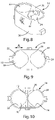
- FIG. 8 is a top perspective view of a lamp base according to a second embodiment.
- FIG. 9 is a top plan view of a lamp base according to the second embodiment.
- FIG. 10 is a bottom plan view of the lamp base according to the second embodiment.
- FIG. 11 is a partial front perspective view of the lamp base and a dual-leg lamp according to the second embodiment.
- FIG. 12 is a bottom plan view of a lamp assembly according to a third embodiment.
- FIG. 13 is a side cross-sectional view of a lamp assembly according to the third embodiment.
- the lamp assembly 10 generally includes a dual-leg lamp 12 , lamp base 14 and an end cap 16 .
- the dual-leg lamp includes two legs 18 and 20 that are both mounted within the lamp base 14 .
- the lamp base 14 defines a pair of oversized holes 22 and 24 that receive the legs 18 and 20 of the lamp 12 .
- only one leg 18 is glued to the lamp base 14 .
- the oversized holes 22 and 24 and absence of glue on one leg 20 permit the lamp 12 to undergo thermal expansion and contraction.
- the lamp assembly 10 is a largely conventional lamp assembly.
- the lamp assembly 10 generally includes a lamp 12 , a lamp base 14 and an end cap 16 .
- the lamp 12 is a generally conventional dual-leg UV lamp. As a result, the lamp 12 will not be described in detail. Suffice it to say that the lamp 12 includes two legs 18 and 20 that are interconnected by bridge 26 . In one embodiment, the legs 18 and 20 of the lamp are generally parallel, and the bridge extends approximately perpendicularly between them.
- the bridge 26 is hollow, thereby providing communication between the interiors of the legs 18 and 20 .
- the lamp 12 further includes a pair of electrodes 28 - 30 —one mounted within each leg 18 and 20 .
- Electrical leads 32 a - b and 34 a - b extend from the electrodes 28 - 30 to the exterior of the lamp 12 .
- the electrical leads 32 a - b and 34 a - b are connected to the end cap 16 , as described in more detail below.
- the lamp 12 is mounted to the lamp base 14 .
- the lamp base 14 is typically configured to fit within a lamp receptacle (not shown) and, if desired, may include mounting tabs and/or other structure to assist in alignment, interfitting and/or interlocking of the lamp base 14 with the lamp receptacle. Accordingly, the design and configuration of the lamp base may vary from application to application as desired to correspond with the intended lamp receptacle.
- the lamp base 14 generally includes a top wall 36 and a side wall 38 extending downwardly from the periphery of the main wall 36 .
- the top wall 36 and side wall 38 cooperatively define an internal space 40 of sufficient size to receive the ends of the legs lamp 12 .
- the lamp base 14 of the illustrated embodiment also includes a divider wall 42 that is disposed within the internal space 40 to provide a degree of separation between the space surrounding each of the legs 18 and 20 .
- the divider wall 42 provides a separator that prevents glue applied to one leg from flowing onto the other leg (see FIG. 7 ). This facilitates the application of glue to only one of the legs 18 and 20 .
- the leg mounting holes 22 and 24 are defined in the top wall 36 . As perhaps best shown in FIGS.
- the legs 18 and 20 of the lamp 12 are fitted into leg mounting holes 22 .
- the leg mounting holes 22 and 24 are oversized in the direction denoted by reference line A in FIG. 3B . This allows for movement of at least one leg 18 and 20 within its corresponding hole 22 and 24 .
- the mounting holes may be oversized in essentially any way that permits the desired leg 18 and 20 movement
- the mounting holes 22 and 24 of the illustrated embodiment are generally elliptical and are elongated in the direction denoted by reference line A in FIG. 3B .
- the elongated mounting holes 22 and 24 permit the generally circular legs 18 and 20 to movement within the mounting holes 22 and 24 .
- FIG. 3B shows leg 18 in mounting hole 22 in a first position in solid lines and in a second position in phantom lines.
- the change in position illustrated in FIG. 3B provides a representation of the range of motion of the legs 18 and 20 within the mounting holes 22 and 24 .
- FIGS. 8-11 show a somewhat different mounting hole shape than shown in FIGS. 3A-C .
- the mounting holes 22 and 24 of FIGS. 8-11 are more irregular shaped than those of FIGS. 3A-C .
- the mounting holes 22 and 24 are oversized (e.g. larger than the corresponding lamp leg 18 and 20 ) in the direction denoted by arrow A to provide sufficient clearance for the legs 18 and 20 to move as the lamp 12 undergoes thermal expansion and contraction.
- the lamp base 14 of the illustrated embodiment defines two oversized mounting holes 22 and 24 , in some applications only one of the mounting holes need be elongated or otherwise oversized.
- the legs 18 and 20 may be secured to the lamp base 12 .
- only leg 18 is secured to the lamp base 12 (see FIG. 7 ). This leaves leg 20 free to move within mounting hole 22 as the lamp undergoes thermal expansion and contraction.
- lamp leg 18 is secured to the lamp base 14 by glue 48 .
- the glue 48 surrounds the leg 18 and interconnects the leg 18 with the lamp base 14 .
- the divider wall 42 helps to retain the glue 48 on one side of the lamp base 14 , thereby leaving leg 20 unglued and free to move within mounting hole 22 .
- the end cap 16 is fitted into the open end of the lamp base 14 (See FIG. 5 ).
- the end cap 16 may be glued, welded or otherwise secured to the lamp base 14 , as desired.
- the end cap 16 includes two pair of electrical prongs 44 a - b and 46 a - b that extend through and protrude from the end cap 16 to provide connectors for electrically connecting the lamp 12 to a power source.
- the prongs 44 a - b and 46 a - b of the illustrated embodiment are configured to be fitted into corresponding sockets (not shown) in the lamp receptacle (not shown).
- the size, shape and arrangement of the prongs 44 a - b and 46 a - b may be selected to correspond with essentially standard specifications to facilitate compatibility.
- the leads 32 a - b and 34 a - b of the lamp 12 are electrically connected to the prongs 44 a - b and 464 a - b , for example, by crimping, soldering or other conventional techniques.
- the end cap 16 is typically configured to fit within a lamp receptacle (not shown) and, if desired, may include mounting tabs and/or other structure to assist in alignment, interfitting and/or interlocking of the lamp base 14 with the lamp receptacle. Accordingly, the design and configuration of the end cap 16 may vary from application to application as desired to correspond with the intended lamp receptacle.
- the lamp assembly 10 may be assembled in a wide variety of ways. However, for purposes of disclosure, one method of assembly will be described. In one embodiment, the lamp assembly 10 is assembled by obtaining a pre-manufactured dual-leg lamp. Dual-leg lamps are available in a wide variety of styles from a wide variety of manufacturers.
- the lamp base 14 and end cap 16 may be manufactured from plastic or other suitable materials. For example, the lamp base 14 and end cap 16 may be injection molded from a plastic material capable of withstanding the temperature extremes associated with the particular application.
- the electrical prongs 44 a - b and 46 a - b are fitted into corresponding apertures in the end cap 16 .
- the prongs 44 a - b and 46 a - b may be retained by a friction fit or by other techniques, such as fasteners or adhesives.
- the lamp 12 is inserted into the lamp base 14 . More specifically, the electrode end of each leg 18 and 20 is inserted the appropriate depth into the leg mounting holes 22 and 24 .
- Glue 48 is applied to the lamp base 14 and the leg 18 to intersecure the lamp 12 and the lamp base 14 .
- the glue 48 may be applied by inverting the lamp base 14 such that the top wall 36 , side wall 38 and divider wall 42 cooperatively define a “cup” surrounding the leg 18 .
- Glue 48 is injected, poured or otherwise supplied to the cup where it surrounds the leg 18 . Once cured, the glue 48 provides the desired bond.
- a variety of glues may be used to secure the lamp 12 to the lamp base 14 .
- the glue 48 may be an epoxy and a high temperature silicon adhesive.
- the end cap 16 is secured to the bottom of the lamp base 14 . This closes the interior space 40 and provides the lamp assembly 10 with the desired electrical prongs 44 a - b and 46 a - b . As noted above, the leads 32 a - b and 34 a - b of the lamp 12 are electrically connected to the prongs 44 a - b and 464 a - b , for example, by soldering or other conventional techniques.
- the end cap 16 may be glued, sonic welded or otherwise interconnected with the lamp base 14 .
- the electrical connections between the leads 32 a - b and 34 a - b and the prongs 44 a - b and 46 a - b may be desirable to make the electrical connections between the leads 32 a - b and 34 a - b and the prongs 44 a - b and 46 a - b before gluing the lamp 12 to the lamp base 14 .
- the legs 18 and 20 are seated in the lamp base 14 , the confines of the lamp base 14 may make it more difficult to make the necessary electrical connections. If the connections are made before glue 48 is applied, they can be made while the lamp end is pushed out from within the lamp base 14 , thereby facilitating the process.
- the lamp 12 is secured to the lamp base 14 using glue 48 applied around leg 18 .
- the lamp 12 may be secured to the lamp base 14 using other connection mechanisms.
- a retaining clamp (not shown) may be used to secure the lamp 12 to the lamp base 14 .
- the clamp may be connected to the lamp base 14 , for example, by fasteners, or it may be larger than the mounting hole 22 and 24 so that it cannot be pulled out of the lamp base 14 once the end cap 16 is installed.
- FIGS. 12 and 13 show an alternative lamp assembly 10 ′ in which the legs 18 ′ and 20 ′ of the lamp 12 ′ may be retained within the lamp base 14 ′ by retaining cups 50 ′ and 52 ′.
- the retaining cups 50 ′ and 52 ′ are sized and shaped so that at least one of them “floats” within the interior space 40 ′ of the lamp base 14 ′ to allow relative movement of the legs 18 ′ and 20 ′ during thermal expansion and contraction.
- the retaining cups 50 ′ and 52 ′ float within the lamp base 14 ′ in the sense that they are capable of moving at least in a direction parallel to the longitudinal extent of the bridge to allow movement during thermal expansion and contraction.
- this embodiment may be altered so that only one of the retaining cups 50 ′ and 52 ′ floats within the lamp base 14 ′.
- the retaining cups 50 ′ and 52 ′ of this embodiment are fitted over the ends of the legs 18 ′ and 20 ′ and secured using glue 48 ′. They may be secured using alternative techniques, if desired. For example, in some applications, it may be possible to frictionally interfit the retaining cups 50 ′ and 52 ′ to the legs 18 ′ and 20 ′. In the alternative embodiment of FIGS.
- the lamp base 14 ′ may define two separate mounting holes 22 and 24 as described above or the two separate holes 22 and 24 may be replaced by single larger hole 22 ′ that is of sufficient size to receive both legs 18 ′ and 20 ′ and permit the legs 18 ′ and 20 ′ to move relative to one another during thermal expansion and contraction.
- this alternative embodiment shows the use of two separate retaining cups 50 ′ and 52 ′
- the present invention may include only one retaining cup in some applications (not shown). In embodiments including only one retaining cup, the retaining cup may be configured to float within the lamp base as described above. However, if the leg that is not connected to the single retaining cup is capable of movement within the lamp base, then the retaining cup may be in a fixed position with respect to the lamp base.
Landscapes
- Fastening Of Light Sources Or Lamp Holders (AREA)
- Non-Portable Lighting Devices Or Systems Thereof (AREA)
- Common Detailed Techniques For Electron Tubes Or Discharge Tubes (AREA)
Priority Applications (5)
| Application Number | Priority Date | Filing Date | Title |
|---|---|---|---|
| US11/972,966 US7568955B2 (en) | 2007-01-16 | 2008-01-11 | Lamp base for dual-leg lamp assembly |
| KR1020097014718A KR101377925B1 (ko) | 2007-01-16 | 2008-01-15 | 이중-레그 램프 조립체용 램프 베이스 |
| PCT/IB2008/050129 WO2008087588A2 (en) | 2007-01-16 | 2008-01-15 | Lamp base for dual-leg lamp assembly |
| JP2009546038A JP5156027B2 (ja) | 2007-01-16 | 2008-01-15 | 二脚ランプ組立品用のランプベース |
| TW097101586A TWI397101B (zh) | 2007-01-16 | 2008-01-16 | 雙管燈組件之燈座 |
Applications Claiming Priority (2)
| Application Number | Priority Date | Filing Date | Title |
|---|---|---|---|
| US88508307P | 2007-01-16 | 2007-01-16 | |
| US11/972,966 US7568955B2 (en) | 2007-01-16 | 2008-01-11 | Lamp base for dual-leg lamp assembly |
Publications (2)
| Publication Number | Publication Date |
|---|---|
| US20080170399A1 US20080170399A1 (en) | 2008-07-17 |
| US7568955B2 true US7568955B2 (en) | 2009-08-04 |
Family
ID=39617616
Family Applications (1)
| Application Number | Title | Priority Date | Filing Date |
|---|---|---|---|
| US11/972,966 Active US7568955B2 (en) | 2007-01-16 | 2008-01-11 | Lamp base for dual-leg lamp assembly |
Country Status (6)
| Country | Link |
|---|---|
| US (1) | US7568955B2 (zh) |
| JP (1) | JP5156027B2 (zh) |
| KR (1) | KR101377925B1 (zh) |
| CN (1) | CN101601117A (zh) |
| TW (1) | TWI397101B (zh) |
| WO (1) | WO2008087588A2 (zh) |
Cited By (1)
| Publication number | Priority date | Publication date | Assignee | Title |
|---|---|---|---|---|
| US20140240971A1 (en) * | 2013-02-25 | 2014-08-28 | Stanley Szprengiel | Multi-Position LED Tube Connector |
Families Citing this family (2)
| Publication number | Priority date | Publication date | Assignee | Title |
|---|---|---|---|---|
| CN114305854A (zh) * | 2021-12-10 | 2022-04-12 | 温州泓力达自动化设备有限公司 | 一种双腿降温辅助物理降温医疗夹具 |
| DE202023100154U1 (de) * | 2023-01-13 | 2024-04-16 | Tridonic Gmbh & Co Kg | Halteadapter zur Nachrüstung von Feuchtraumleuchten |
Citations (11)
| Publication number | Priority date | Publication date | Assignee | Title |
|---|---|---|---|---|
| US2004564A (en) | 1933-06-03 | 1935-06-11 | Gen Electric | Gaseous electric discharge lamp device |
| US2020718A (en) | 1933-10-04 | 1935-11-12 | Gen Electric | Electric device |
| JPH0439834A (ja) | 1990-06-05 | 1992-02-10 | Toshiba Lighting & Technol Corp | 蛍光ランプ |
| US5252890A (en) | 1989-09-12 | 1993-10-12 | Toshiba Lighting And Technology Corporation | Compact type fluorescent lamp device having crooked arc path |
| US5455484A (en) | 1994-09-16 | 1995-10-03 | Matsushita Electric Works R&D Laboratory, Inc. | Adapter for simultaneously powering multiple compact fluorescent lamps utilizing an electronic ballast circuit |
| DE19857721A1 (de) | 1997-12-18 | 1999-06-24 | Gen Electric | Kunststoffkappe für kompakte Leuchtstofflampen |
| US6001351A (en) * | 1993-05-18 | 1999-12-14 | I.D.M. Immuno-Designed Molecules | Macrophages, process for preparing the same and their use as active substances of pharmaceutical compositions |
| US6005337A (en) | 1996-12-30 | 1999-12-21 | General Electric Company | Single-ended discharge lamp |
| US6597091B2 (en) * | 2001-02-16 | 2003-07-22 | Ic Tech Co., Ltd | Halogen lamp supporting device |
| US6971917B2 (en) * | 2003-02-12 | 2005-12-06 | Vossloh-Schwabe Deutschland Gmbh | Socket for an electrically operated device |
| US7025634B1 (en) * | 2005-05-16 | 2006-04-11 | Osram Sylvania Inc. | Lamp socket |
Family Cites Families (3)
| Publication number | Priority date | Publication date | Assignee | Title |
|---|---|---|---|---|
| JPS6358753A (ja) * | 1986-08-29 | 1988-03-14 | Hitachi Ltd | 低圧水銀蒸気放電灯 |
| JPH0398235A (ja) * | 1989-09-12 | 1991-04-23 | Toshiba Lighting & Technol Corp | けい光ランプ |
| JPH03163726A (ja) * | 1989-11-20 | 1991-07-15 | Toshiba Lighting & Technol Corp | けい光ランプ |
-
2008
- 2008-01-11 US US11/972,966 patent/US7568955B2/en active Active
- 2008-01-15 JP JP2009546038A patent/JP5156027B2/ja active Active
- 2008-01-15 KR KR1020097014718A patent/KR101377925B1/ko active IP Right Grant
- 2008-01-15 WO PCT/IB2008/050129 patent/WO2008087588A2/en active Application Filing
- 2008-01-15 CN CNA2008800023044A patent/CN101601117A/zh active Pending
- 2008-01-16 TW TW097101586A patent/TWI397101B/zh active
Patent Citations (11)
| Publication number | Priority date | Publication date | Assignee | Title |
|---|---|---|---|---|
| US2004564A (en) | 1933-06-03 | 1935-06-11 | Gen Electric | Gaseous electric discharge lamp device |
| US2020718A (en) | 1933-10-04 | 1935-11-12 | Gen Electric | Electric device |
| US5252890A (en) | 1989-09-12 | 1993-10-12 | Toshiba Lighting And Technology Corporation | Compact type fluorescent lamp device having crooked arc path |
| JPH0439834A (ja) | 1990-06-05 | 1992-02-10 | Toshiba Lighting & Technol Corp | 蛍光ランプ |
| US6001351A (en) * | 1993-05-18 | 1999-12-14 | I.D.M. Immuno-Designed Molecules | Macrophages, process for preparing the same and their use as active substances of pharmaceutical compositions |
| US5455484A (en) | 1994-09-16 | 1995-10-03 | Matsushita Electric Works R&D Laboratory, Inc. | Adapter for simultaneously powering multiple compact fluorescent lamps utilizing an electronic ballast circuit |
| US6005337A (en) | 1996-12-30 | 1999-12-21 | General Electric Company | Single-ended discharge lamp |
| DE19857721A1 (de) | 1997-12-18 | 1999-06-24 | Gen Electric | Kunststoffkappe für kompakte Leuchtstofflampen |
| US6597091B2 (en) * | 2001-02-16 | 2003-07-22 | Ic Tech Co., Ltd | Halogen lamp supporting device |
| US6971917B2 (en) * | 2003-02-12 | 2005-12-06 | Vossloh-Schwabe Deutschland Gmbh | Socket for an electrically operated device |
| US7025634B1 (en) * | 2005-05-16 | 2006-04-11 | Osram Sylvania Inc. | Lamp socket |
Non-Patent Citations (1)
| Title |
|---|
| International Search Report and the Written Opinion of the International Searching Authority, mailed Sep. 18, 2008. |
Cited By (2)
| Publication number | Priority date | Publication date | Assignee | Title |
|---|---|---|---|---|
| US20140240971A1 (en) * | 2013-02-25 | 2014-08-28 | Stanley Szprengiel | Multi-Position LED Tube Connector |
| US9046256B2 (en) * | 2013-02-25 | 2015-06-02 | Component Hardware Group, Inc. | Connector having a cylindrical body with a flange and an integral insert with a rectangular bore |
Also Published As
| Publication number | Publication date |
|---|---|
| KR20090101353A (ko) | 2009-09-25 |
| KR101377925B1 (ko) | 2014-03-25 |
| TWI397101B (zh) | 2013-05-21 |
| WO2008087588A4 (en) | 2009-01-29 |
| WO2008087588A2 (en) | 2008-07-24 |
| JP2010516039A (ja) | 2010-05-13 |
| US20080170399A1 (en) | 2008-07-17 |
| WO2008087588A3 (en) | 2008-11-06 |
| JP5156027B2 (ja) | 2013-03-06 |
| CN101601117A (zh) | 2009-12-09 |
| TW200844367A (en) | 2008-11-16 |
Similar Documents
| Publication | Publication Date | Title |
|---|---|---|
| US9829162B2 (en) | String lamp | |
| US7568955B2 (en) | Lamp base for dual-leg lamp assembly | |
| US20160341369A1 (en) | Electrical connection structure of lamp cap | |
| EP3273159A1 (en) | Integrated electric connection structure for led lamp | |
| TWI342938B (zh) | ||
| US20090167184A1 (en) | Compact fluorescent lamp with mechanical support means and starting aid | |
| US9841148B1 (en) | Electrical connection structure of lamp cap | |
| CN206582574U (zh) | 全玻璃透射par灯 | |
| US20100314167A1 (en) | Coaxial line with supporting rings | |
| US6102551A (en) | Christmas lamp assembly | |
| JPH04229949A (ja) | 多面反射型ランプ | |
| US6707238B2 (en) | Compact low-pressure discharge lamp | |
| US6876137B2 (en) | Discharge lamp with discharge tube fixture arrangement and method for manufacturing the same | |
| EP2078326B1 (en) | Reversible lamp base | |
| US8188657B2 (en) | Illuminating lamp and method of making same | |
| US20100187972A1 (en) | Compact fluorescent lamp envelope and method of manufacture | |
| CN105841108A (zh) | 自动组装灯头 | |
| JPH0723894Y2 (ja) | ランプ装置 | |
| GB2169757A (en) | Adaptor for lamp brackets | |
| US7029160B2 (en) | Lamp wedge base | |
| JPH0436053Y2 (zh) | ||
| TWI449223B (zh) | 發光二極體導線架 | |
| JPS6262402B2 (zh) | ||
| US20100311279A1 (en) | Electrical Connector and Illuminating Module | |
| CA2607895A1 (en) | Light string |
Legal Events
| Date | Code | Title | Description |
|---|---|---|---|
| AS | Assignment |
Owner name: ACCESS BUSINESS GROUP INTERNATIONAL LLC, MICHIGAN Free format text: ASSIGNMENT OF ASSIGNORS INTEREST;ASSIGNORS:STONER, WILLIAM T., JR.;VECZIEDINS, KARLIS;GREENE, MICHAEL K.;REEL/FRAME:020357/0145;SIGNING DATES FROM 20080109 TO 20080110 |
|
| FEPP | Fee payment procedure |
Free format text: PAYOR NUMBER ASSIGNED (ORIGINAL EVENT CODE: ASPN); ENTITY STATUS OF PATENT OWNER: LARGE ENTITY |
|
| STCF | Information on status: patent grant |
Free format text: PATENTED CASE |
|
| FPAY | Fee payment |
Year of fee payment: 4 |
|
| FPAY | Fee payment |
Year of fee payment: 8 |
|
| MAFP | Maintenance fee payment |
Free format text: PAYMENT OF MAINTENANCE FEE, 12TH YEAR, LARGE ENTITY (ORIGINAL EVENT CODE: M1553); ENTITY STATUS OF PATENT OWNER: LARGE ENTITY Year of fee payment: 12 |