US7467930B2 - Magnetically levitated pump utilizing magnetic bearings - Google Patents
Magnetically levitated pump utilizing magnetic bearings Download PDFInfo
- Publication number
- US7467930B2 US7467930B2 US10/968,931 US96893104A US7467930B2 US 7467930 B2 US7467930 B2 US 7467930B2 US 96893104 A US96893104 A US 96893104A US 7467930 B2 US7467930 B2 US 7467930B2
- Authority
- US
- United States
- Prior art keywords
- impeller
- ferromagnetic body
- casing
- electro
- side ferromagnetic
- Prior art date
- Legal status (The legal status is an assumption and is not a legal conclusion. Google has not performed a legal analysis and makes no representation as to the accuracy of the status listed.)
- Active, expires
Links
Images


Classifications
-
- F—MECHANICAL ENGINEERING; LIGHTING; HEATING; WEAPONS; BLASTING
- F04—POSITIVE - DISPLACEMENT MACHINES FOR LIQUIDS; PUMPS FOR LIQUIDS OR ELASTIC FLUIDS
- F04D—NON-POSITIVE-DISPLACEMENT PUMPS
- F04D29/00—Details, component parts, or accessories
- F04D29/04—Shafts or bearings, or assemblies thereof
- F04D29/046—Bearings
- F04D29/048—Bearings magnetic; electromagnetic
-
- A—HUMAN NECESSITIES
- A61—MEDICAL OR VETERINARY SCIENCE; HYGIENE
- A61M—DEVICES FOR INTRODUCING MEDIA INTO, OR ONTO, THE BODY; DEVICES FOR TRANSDUCING BODY MEDIA OR FOR TAKING MEDIA FROM THE BODY; DEVICES FOR PRODUCING OR ENDING SLEEP OR STUPOR
- A61M60/00—Blood pumps; Devices for mechanical circulatory actuation; Balloon pumps for circulatory assistance
- A61M60/10—Location thereof with respect to the patient's body
- A61M60/122—Implantable pumps or pumping devices, i.e. the blood being pumped inside the patient's body
- A61M60/165—Implantable pumps or pumping devices, i.e. the blood being pumped inside the patient's body implantable in, on, or around the heart
- A61M60/178—Implantable pumps or pumping devices, i.e. the blood being pumped inside the patient's body implantable in, on, or around the heart drawing blood from a ventricle and returning the blood to the arterial system via a cannula external to the ventricle, e.g. left or right ventricular assist devices
-
- A—HUMAN NECESSITIES
- A61—MEDICAL OR VETERINARY SCIENCE; HYGIENE
- A61M—DEVICES FOR INTRODUCING MEDIA INTO, OR ONTO, THE BODY; DEVICES FOR TRANSDUCING BODY MEDIA OR FOR TAKING MEDIA FROM THE BODY; DEVICES FOR PRODUCING OR ENDING SLEEP OR STUPOR
- A61M60/00—Blood pumps; Devices for mechanical circulatory actuation; Balloon pumps for circulatory assistance
- A61M60/20—Type thereof
- A61M60/205—Non-positive displacement blood pumps
- A61M60/216—Non-positive displacement blood pumps including a rotating member acting on the blood, e.g. impeller
-
- A—HUMAN NECESSITIES
- A61—MEDICAL OR VETERINARY SCIENCE; HYGIENE
- A61M—DEVICES FOR INTRODUCING MEDIA INTO, OR ONTO, THE BODY; DEVICES FOR TRANSDUCING BODY MEDIA OR FOR TAKING MEDIA FROM THE BODY; DEVICES FOR PRODUCING OR ENDING SLEEP OR STUPOR
- A61M60/00—Blood pumps; Devices for mechanical circulatory actuation; Balloon pumps for circulatory assistance
- A61M60/40—Details relating to driving
- A61M60/403—Details relating to driving for non-positive displacement blood pumps
- A61M60/419—Details relating to driving for non-positive displacement blood pumps the force acting on the blood contacting member being permanent magnetic, e.g. from a rotating magnetic coupling between driving and driven magnets
-
- A—HUMAN NECESSITIES
- A61—MEDICAL OR VETERINARY SCIENCE; HYGIENE
- A61M—DEVICES FOR INTRODUCING MEDIA INTO, OR ONTO, THE BODY; DEVICES FOR TRANSDUCING BODY MEDIA OR FOR TAKING MEDIA FROM THE BODY; DEVICES FOR PRODUCING OR ENDING SLEEP OR STUPOR
- A61M60/00—Blood pumps; Devices for mechanical circulatory actuation; Balloon pumps for circulatory assistance
- A61M60/40—Details relating to driving
- A61M60/403—Details relating to driving for non-positive displacement blood pumps
- A61M60/422—Details relating to driving for non-positive displacement blood pumps the force acting on the blood contacting member being electromagnetic, e.g. using canned motor pumps
-
- A—HUMAN NECESSITIES
- A61—MEDICAL OR VETERINARY SCIENCE; HYGIENE
- A61M—DEVICES FOR INTRODUCING MEDIA INTO, OR ONTO, THE BODY; DEVICES FOR TRANSDUCING BODY MEDIA OR FOR TAKING MEDIA FROM THE BODY; DEVICES FOR PRODUCING OR ENDING SLEEP OR STUPOR
- A61M60/00—Blood pumps; Devices for mechanical circulatory actuation; Balloon pumps for circulatory assistance
- A61M60/80—Constructional details other than related to driving
- A61M60/802—Constructional details other than related to driving of non-positive displacement blood pumps
- A61M60/818—Bearings
- A61M60/82—Magnetic bearings
-
- F—MECHANICAL ENGINEERING; LIGHTING; HEATING; WEAPONS; BLASTING
- F04—POSITIVE - DISPLACEMENT MACHINES FOR LIQUIDS; PUMPS FOR LIQUIDS OR ELASTIC FLUIDS
- F04D—NON-POSITIVE-DISPLACEMENT PUMPS
- F04D13/00—Pumping installations or systems
- F04D13/02—Units comprising pumps and their driving means
- F04D13/06—Units comprising pumps and their driving means the pump being electrically driven
- F04D13/0666—Units comprising pumps and their driving means the pump being electrically driven the motor being of the plane gap type
-
- A—HUMAN NECESSITIES
- A61—MEDICAL OR VETERINARY SCIENCE; HYGIENE
- A61M—DEVICES FOR INTRODUCING MEDIA INTO, OR ONTO, THE BODY; DEVICES FOR TRANSDUCING BODY MEDIA OR FOR TAKING MEDIA FROM THE BODY; DEVICES FOR PRODUCING OR ENDING SLEEP OR STUPOR
- A61M60/00—Blood pumps; Devices for mechanical circulatory actuation; Balloon pumps for circulatory assistance
- A61M60/10—Location thereof with respect to the patient's body
- A61M60/122—Implantable pumps or pumping devices, i.e. the blood being pumped inside the patient's body
- A61M60/126—Implantable pumps or pumping devices, i.e. the blood being pumped inside the patient's body implantable via, into, inside, in line, branching on, or around a blood vessel
- A61M60/148—Implantable pumps or pumping devices, i.e. the blood being pumped inside the patient's body implantable via, into, inside, in line, branching on, or around a blood vessel in line with a blood vessel using resection or like techniques, e.g. permanent endovascular heart assist devices
Definitions
- the present invention relates to a magnetically levitated pump and, more specifically, to a clean pump utilizing a magnetic bearing, which is used, by way of example, in a medical instrument such as an artificial heart.
- FIG. 11 shows a magnetically levitated pump of a first prior art example having an electro-magnet 31 for magnetic bearing and a motor 13 provided on opposite sides of an impeller 23 (see FIG. 5 of Japanese Patent Laying-Open No. 2002-130177 and FIG. 16A of U.S. Pat. No. 6,626,644 B2).
- the magnetically levitated pump 1 of the first prior art example is formed of a motor unit 10 , a pump unit 20 and a magnetic bearing unit 30 .
- a pump chamber 22 is provided in a casing 21 of pump unit 20 .
- Impeller 23 rotates in this pump chamber 22 .
- Impeller 23 has a plurality of blades, not shown.
- Casing 21 is formed of a non-magnetic material, and impeller 23 is pivotally supported by a non-controlled magnetic bearing and a controlled magnetic bearing.
- the non-controlled magnetic bearing is formed of a rotor-side permanent magnet 14 and an impeller-side permanent magnet 24
- the controlled magnetic bearing is formed of an electro-magnet 31 for magnetic bearing and a soft magnetic member 27 opposite to the electro-magnet and to a position sensor.
- Impeller-side permanent magnet 24 is divided along the circumferential direction of impeller 23 , and adjacent magnets are magnetized to have mutually opposite polarities.
- a rotor 12 is provided pivotally supported by a fixed shaft 11 , outside the pump chamber 22 .
- Rotor 12 rotates, driven by motor 13 .
- Rotor 12 has rotor-side permanent magnets 14 same in number as the impeller-side magnets, opposite to impeller-side permanent magnets 24 on impeller 23 and generating an attracting power.
- Electro-magnet 31 for magnetic bearing has a C-shape
- position sensor 47 is a magnetic sensor.
- Impeller 23 is isolated from rotor 12 by casing 21 , and is free from any contamination from electro-magnets 31 for magnetic bearing, and therefore, the fluid (when applied as a blood pump, blood) emitted from magnetically levitated pump 1 is kept clean.
- FIG. 12 shows the magnetically levitated pump of the second prior art example, in which motor 13 and electro-magnets 31 for magnetic bearing are arranged in a space on the same side (see FIG. 3 of Japanese Patent Laying-Open No. 2002-130177 and FIG. 3 of U.S. Pat. No. 6,626,644 B2)
- FIG. 12 the magnetically levitated pump of the second prior art example will be described. Portions having the same functions as FIG. 11 are denoted by the same reference characters, and description thereof will not be repeated.
- the magnetically levitated pump shown in FIG. 12 has motor 13 and electro-magnets 31 for magnetic bearing arranged in a space on the same side. Because of this structure, the axial length of the pump (hereinafter referred to as pump length L 2 ) consisting of an actuator unit 40 , pump unit 20 and casing unit 50 is made much shorter than pump length L 1 of the first prior art example shown in FIG. 11 .
- the magnetically levitated pump shown in FIG. 12 includes an actuator unit 40 , pump unit 20 and casing unit 50 .
- Pump chamber 22 is provided in casing 21 of pump unit 20 , and impeller 23 rotates in pump chamber 22 .
- Casing 21 is formed of plastic, ceramic, metal or the like. Of casing 21 , an electro-magnets/impeller dividing wall 35 between actuator unit 40 and impeller 23 , and a position sensor/impeller dividing wall 36 between position sensor 47 and impeller 23 cannot be formed of a magnetic material. Therefore, electro-magnets/impeller dividing wall 35 and position sensor/impeller dividing wall 36 are formed of a non-magnetic material.
- Impeller 23 is supported by a non-controlled magnetic bearing and a controlled magnetic bearing.
- the non-controlled magnetic bearing is formed of an impeller-side permanent magnet 24 and rotor-side permanent magnets 14 .
- Controlled magnetic bearing is formed of a soft magnetic member 26 opposite to the electro-magnets for magnetic bearing of impeller 23 and electro-magnets 31 for magnetic bearing.
- Impeller-side permanent magnet 24 and soft magnetic member 26 opposite to the electro-magnets for magnetic bearing are embedded.
- Impeller-side permanent magnet 24 is divided along the circumferential direction of impeller 23 , and adjacent magnets are magnetized to have mutually opposite polarities.
- a rotor 12 is provided pivotally supported by a fixed shaft 11 , outside the pump chamber 22 .
- Rotor 12 rotates, driven by motor 13 .
- Rotor 12 has rotor-side permanent magnets 14 same in number as the impeller-side magnets, opposite to impeller-side permanent magnets 24 on impeller 23 and generating an attracting power.
- electro-magnets 31 for magnetic bearing are provided.
- a ring-shaped, impeller-side ferromagnetic body 29 and a soft magnetic member 45 opposite to position sensor are embedded.
- position sensor 47 is arranged, and opposite to impeller-side ferromagnetic body 29 , a ring-shaped, casing-side permanent magnet 28 is arranged.
- the attractive force of impeller-side ferromagnetic body 29 and ring-shaped, casing-side permanent magnet 28 also attains support of impeller 23 in the radial direction.
- Impeller 23 is movable in the axial direction in pump chamber 22 , and materials and shapes of casing-side permanent magnet 28 and impeller-side ferromagnetic body 29 as well as the arrangement of casing-side permanent magnet 28 are determined so that the attractive force acting between casing-side permanent magnet 28 and impeller-side ferromagnetic body 29 is always larger than the attractive force acting on impeller-side permanent magnets 24 and rotor-side permanent magnets 14 within this movable range.
- impeller-side permanent magnets 24 and rotor-side permanent magnets 14 are counterbalanced by the attractive force acting between impeller-side ferromagnetic body 29 and casing-side permanent magnet 28 , whereby impeller 23 can be held at the center of pump chamber 22 .
- Magnetically levitated pump 1 shown in FIG. 11 has a problem that axial length of electro-magnets 31 for magnetic bearing in magnetic bearing unit 30 is long, and therefore pump length L 1 including motor unit 10 , pump unit 20 and magnetic bearing unit 30 becomes long.
- magnetic bearing unit 30 and motor 13 are arranged in a space on the same side, so that the pump length including actuator unit 40 , pump unit 20 and casing unit 50 , that is, the pump length L 2 along the axial direction mentioned above, is made shorter than pump length L 1 of the first prior art example shown in FIG. 11 , and the entire pump is made compact.
- the magnetically levitated pump is to be used as an implanted blood pump, however, further size reduction of the pump is desirable.
- a main object of the present invention is to provide a magnetically levitated pump that is made compact by (1) shortening axial length of the pump by arranging electro-magnets 31 for magnetic bearing and motor 13 in the same direction with respect to impeller 23 , and by (2) reducing negative stiffness in the axial direction of impeller 23 generated by the mechanism for radially supporting impeller 23 realized by the attractive force of impeller-side ferromagnetic body 29 and ring-shaped, casing-side permanent magnet 28 having the structure shown in FIG. 12 of the second prior art example, to suppress maximum required attractive force f 2 of electro-magnets 31 for magnetic bearing and thereby to make shorter the length L 5 of the electro-magnets for magnetic bearing.
- FIG. 1 shows a magnetically levitated pump 1 including: a pump unit 20 provided with a disk-shaped impeller 23 for feeding liquid; and an actuator unit 40 having a motor rotor 15 transmitting rotary driving force to pump unit 20 and electro-magnets 31 for magnetic bearing arranged in the same direction to impeller 23 ; wherein a current flowing through electro-magnets 31 for magnetic bearing is controlled to balance the attractive force between electro-magnets 31 for magnetic bearing and soft magnetic member 26 (first ferromagnetic body) opposite to the electro-magnets provided on one of the opposite surfaces of disk-shaped impeller 23 (hereinafter referred to as the actuator-facing impeller surface) opposite to electro-magnets 31 for magnetic bearing, the attractive force between an impeller-side ferromagnetic body 51 (second ferromagnetic body) provided on the other one of the opposite surfaces of disk-shaped impeller 23 that faces to casing unit 50 (hereinafter referred to as the casing-faced impeller surface) and a casing-side ferromagnetic
- opposite surfaces of impeller-side ferromagnetic body 51 (second ferromagnetic body) and casing-side ferromagnetic body 52 (third ferromagnetic body) have different shapes, so that the maximum required attractive force of electro-magnets 31 for magnetic bearing is reduced from f 1 for the example of FIG. 12 to f 2 , whereby the length of the electro-magnets for the magnetic bearing is reduced from L 4 of FIG. 12 to L 5 of FIG. 1 and the magnetically levitated pump 1 is made compact.
- FIG. 1 shows a magnetically levitated pump 1 including a pump unit 20 and an actuator unit 40 having a motor rotor 15 and electro-magnets 31 for magnetic bearing arranged in the same direction to impeller 23 , and a casing unit 50 .
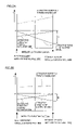
- FIG. 2A is a first characteristic diagram of impeller levitation position and impeller force, representing a relation between the position of impeller levitation in pump chamber 22 (abscissa) and the force acting on impeller 23 (ordinate).
- FIG. 2B is a second characteristic diagram of impeller levitation position and impeller force, representing a relation between the position of impeller levitation in pump chamber 22 (abscissa) and the force acting on impeller 23 (ordinate).
- FIG. 3 is an illustration showing ferromagnetic bodies having opposite surfaces of different shapes, that is, the inner diameter of ring-shaped impeller-side ferromagnetic body 51 (second ferromagnetic body) is made larger than the inner diameter of ring-shaped casing-side ferromagnetic body 52 (third ferromagnetic body), and the outer diameter of the second ferromagnetic body is made smaller than the outer diameter of the third ferromagnetic body.
- FIG. 4 is an illustration showing ferromagnetic bodies having opposite surfaces of different shapes, that is, the inner diameter of ring-shaped impeller-side ferromagnetic body 51 (second ferromagnetic body) is made smaller than the inner diameter of ring-shaped casing-side ferromagnetic body 52 (third ferromagnetic body), and the outer diameter of the second ferromagnetic body is made larger than the outer diameter of the third ferromagnetic body.
- FIG. 5 is an illustration showing ferromagnetic bodies having opposite surfaces of different shapes, that is, the inner and outer diameters of ring-shaped impeller-side ferromagnetic body 51 (second ferromagnetic body) are made larger than the inner and outer diameters of casing-side ferromagnetic body 52 (third ferromagnetic body), respectively.
- FIG. 6 is an illustration showing ferromagnetic bodies having opposite surfaces of different shapes, that is, the inner and outer diameters of ring-shaped impeller-side ferromagnetic body 51 (second ferromagnetic body) are made smaller than the inner and outer diameters of casing-side ferromagnetic body 52 (third ferromagnetic body), respectively.
- FIG. 7 is an illustration showing ferromagnetic-bodies having opposite surfaces of different shapes, that is, impeller-side ferromagnetic body 51 (second ferromagnetic body) has a ring-shape, and casing-side ferromagnetic body 52 (third ferromagnetic body) is formed of four bar-magnets all magnetized in the same direction.
- FIG. 8 is an illustration showing ferromagnetic bodies having opposite surfaces of different shapes, that is, casing-side ferromagnetic body 52 (third ferromagnetic body) has a ring-shape, and impeller-side ferromagnetic body 51 (second ferromagnetic body) is formed of sixteen bar-magnets all magnetized in the same direction.
- FIG. 9 is an illustration showing ferromagnetic bodies having opposite surfaces of different shapes, that is, casing-side ferromagnetic body 52 (third ferromagnetic body) has a ring-shape, and impeller-side ferromagnetic body 51 (second ferromagnetic body) is formed of two plate-magnets magnetized in the same direction.
- FIG. 10 is an illustration showing ferromagnetic bodies having opposite surfaces of different shapes, that is, impeller-side ferromagnetic body 51 (second ferromagnetic body) has a ring-shape, and casing-side ferromagnetic body 52 (third ferromagnetic body) is formed of two plate-magnets magnetized in the same direction.
- FIG. 11 shows a magnetically levitated pump of a first prior art example having an electro-magnet 31 for magnetic bearing and a motor 13 provided on opposite sides of an impeller 23 .
- FIG. 12 shows a magnetically levitated pump of the second prior art example, having motor 13 and electro-magnets 31 for magnetic bearing arranged in a space on the same side.
- FIG. 13 shows a magnetically levitated pump with a leakage flux shielding structure in which a ferromagnetic body 53 (fourth ferromagnetic body) is arranged on that side of casing-side ferromagnetic body 52 which does not face to impeller 23 .
- the invention according to the first embodiment is, as shown in FIG. 1 , directed to a magnetically levitated pump 1 including: a pump unit 20 provided with a disk-shaped impeller 23 for feeding liquid; and an actuator unit 40 having a motor rotor 15 transmitting rotary driving force to impeller 23 and electro-magnets 31 for magnetic bearing exerting an attractive force on impeller 23 , arranged in the same direction to impeller 23 ; wherein
- a soft magnetic member 26 opposite to the electro-magnets is provided on the actuator-facing impeller surface, opposite to elector-magnets 31 for magnetic bearing;
- an impeller-side ferromagnetic body 51 (second ferromagnetic body) is provided on the casing-faced impeller surface;
- a casing-side ferromagnetic body 52 (third ferromagnetic body) is provided opposite to impeller-side ferromagnetic body 51 (second ferromagnetic body) for attracting impeller 23 toward the casing 50 ;
- a current flowing through electro-magnets 31 for magnetic bearing is controlled to balance (1) “the attractive force between electro-magnets 31 for magnetic bearing and soft magnetic member 26 (first ferromagnetic body)”, (2) “the attractive force between impeller-side ferromagnetic body 51 (second ferromagnetic body) and casing-side ferromagnetic body 52 (third ferromagnetic body)”, (3) “the force acting on impeller 23 generated by the rotary driving means (in FIG. 1 , the attractive force between impeller-side permanent magnets 24 and rotor-side permanent magnets 14 )” and (4) “disturbances acting on impeller 23 ”, so that the impeller is magnetically levitated; and wherein
- impeller-side ferromagnetic body 51 second ferromagnetic body
- casing-side ferromagnetic body 52 third ferromagnetic body
- the invention according to the second embodiment is, as shown in FIGS. 3 to 10 , directed to the magnetically levitated pump of the first embodiment, wherein impeller-side ferromagnetic body 51 (second ferromagnetic body) or casing-side ferromagnetic body 52 (third ferromagnetic body) has a ring-shape.
- the invention according to the third embodiment is, as shown in FIGS. 7 to 10 , directed to the magnetically levitated pump of the first or second embodiment, wherein impeller-side ferromagnetic body 51 (second ferromagnetic body) or casing-side ferromagnetic body 52 (third ferromagnetic body) is formed of a plurality of ferromagnetic bodies arranged in the circumferential direction.
- the invention according to the fourth embodiment is, as shown in FIG. 3 or 5 or FIGS. 7 to 10 , directed to the magnetically levitated pump of the first to third embodiments, wherein the diameter of an approximated inscribed circle of impeller-side ferromagnetic body 51 (second ferromagnetic body) is made larger than the diameter of an approximated inscribed circle of casing-side ferromagnetic body 52 (third ferromagnetic body).
- the invention according to the fifth embodiment is, as shown in FIG. 4 or 6 , directed to the magnetically levitated pump of the first to third embodiments, wherein the diameter of an approximated inscribed circle of impeller-side ferromagnetic body 51 (second ferromagnetic body) is made smaller than the diameter of an approximated inscribed circle of casing-side ferromagnetic body 52 (third ferromagnetic body).
- the invention according to the sixth embodiment is, as shown in FIG. 4 or 5 , directed to the magnetically levitated pump of the first to third embodiments, wherein the diameter of an approximated circumscribed circle of impeller-side ferromagnetic body 51 (second ferromagnetic body) is made larger than the diameter of an approximated circumscribed circle of casing-side ferromagnetic body 52 (third ferromagnetic body).
- the invention according to the seventh embodiment is, as shown in FIG. 3 or FIGS. 6 to 10 , directed to the magnetically levitated pump of the first to third embodiments, wherein the diameter of an approximated circumscribed circle of impeller-side ferromagnetic body 51 (second ferromagnetic body) is made smaller than the diameter of an approximated circumscribed circle of casing-side ferromagnetic body 52 (third ferromagnetic body).
- the invention according to the eighth embodiment is directed to the magnetically levitated pump of the first to seventh embodiments, wherein impeller-side ferromagnetic body 51 (second ferromagnetic body) is a permanent magnet, or casing-side ferromagnetic body 52 (third ferromagnetic body) is a permanent magnet.
- the invention according to the ninth embodiment is, as shown in FIG. 13 , directed to the magnetically levitated pump of the first to eighth embodiments, wherein a ferromagnetic body 53 (fourth ferromagnetic body) is arranged on that side of casing-side ferromagnetic body 52 (third ferromagnetic body) which does not face to impeller 23 , so as to suppress leakage flux to the outside of the pump.
- a ferromagnetic body 53 fourth ferromagnetic body
- casing-side ferromagnetic body 52 third ferromagnetic body
- the invention according to the tenth embodiment is, as shown in FIG. 1 , directed to the magnetically levitated pump of the first to ninth embodiments, wherein the rotor-side permanent magnet 14 (first permanent magnet) is arranged on that surface of rotor 12 which faces impeller 23 , and the impeller-side permanent magnet 24 (second permanent magnet) is arranged opposite thereto on the surface of impeller 23 , whereby a magnetic coupling is formed by rotor-side permanent magnet 14 and impeller-side permanent magnet 24 , rotor 12 is rotated and impeller 23 is driven and rotated.
- first permanent magnet first permanent magnet
- the impeller-side permanent magnet 24 second permanent magnet
- the invention according to the eleventh embodiment is directed to the magnetically levitated pump of the first to tenth embodiments, used as a blood pump.
- FIG. 1 shows a magnetically levitated pump in which, similar to the second prior art example, motor 13 and electro-magnets 31 for magnetic bearing are arranged in a space on the same side.
- motor 13 and electro-magnets 31 for magnetic bearing are arranged in a space on the same side.
- magnetically levitated pump 1 of the present invention shown in FIG. 1 includes: a pump unit 20 provided with a disk-shaped impeller 23 for feeding liquid; an actuator unit 40 having a motor 13 for rotating impeller 23 and electro-magnets 31 for magnetic bearing exerting an attractive force on impeller 23 , arranged in the same direction to impeller 23 ; and a casing unit 50 having a position sensor 47 arranged thereon, for measuring levitation position of impeller 23 .
- a current flowing through electro-magnets 31 for magnetic bearing is controlled to balance the attractive force between electro-magnets 31 for magnetic bearing and soft magnetic member 26 (first ferromagnetic body) opposite to the electro-magnets provided on the actuator-facing impeller surface opposite to electro-magnets 31 for magnetic bearing, the attractive force between an impeller-side ferromagnetic body 51 (second ferromagnetic body) provided on the casing-faced impeller surface and a casing-side ferromagnetic body 52 (third ferromagnetic body) opposite to impeller-side ferromagnetic body 51 (second ferromagnetic body) and attracting impeller 23 toward the casing 50 , the force acting on impeller generated by the rotary driving means (in FIG. 1 , the attractive force between impeller-side permanent magnets 24 and rotor-side permanent magnets 14 ) and disturbance influencing the impeller, so that the impeller is magnetically levitated.
- opposite surfaces of impeller-side ferromagnetic body 51 (second ferromagnetic body) and casing-side ferromagnetic body 52 (third ferromagnetic body) have different shapes, so that the maximum required attractive force of electro-magnets 31 for magnetic bearing is reduced from f 1 of the second prior art example to f 2 , whereby the length of the electro-magnets of the magnetic bearing is reduced from L 4 of the second prior art example to L 5 , and as a result, the magnetically levitated pump can be made compact by a volume corresponding to a cylindrical body of La ⁇ Lb, that is the product of axial length La of pump outer housing and reduction width Lb in diametral direction of pump outer housing.
- FIGS. 2A and 2B are characteristic diagrams of impeller levitation position and impeller force, representing a relation between the position of impeller levitation from electro-magnets/impeller dividing wall 35 and position sensor/impeller dividing wall 36 in pump chamber 22 (abscissa) and the force acting on impeller 23 (ordinate).
- FIG. 2A is a characteristic diagram of impeller levitation position and impeller force of the conventional structure shown in FIG. 12
- FIG. 2B is a characteristic diagram of impeller levitation position and impeller force of the structure of the present invention shown in FIG. 1 . Both figures represent a state in which the attractive forces Fm 1 and Fm 2 to the direction of the actuator generated between impeller-side permanent magnets 24 and rotor-side permanent magnets 14 are the same.
- the abscissa represents the distance from electro-magnets/impeller dividing wall 35 to impeller 23 , in pump chamber 22 .
- the ordinate represents the force acting on impeller 23 .
- (1) attractive force Fc to the casing side generated between impeller-side ferromagnetic body 51 (second ferromagnetic body) and the casing-side ferromagnetic body 52 (third ferromagnetic body) and (2) attractive force Fm to the actuator side generated between impeller-side permanent magnets 24 and rotor-side permanent magnets 14 are denoted.
- an electro-magnet attractive force Fr required between electro-magnets 31 for magnetic bearing and soft magnetic member 26 opposite to the electro-magnets for levitating impeller 23 to the levitation position against the above-identified attractive forces is calculated by adding the attractive force Fc to the casing side and attractive force Fm to the actuator side, and denoted.
- the attractive force by which impeller 23 is attracted to the side of casing is indicated as (+) along the ordinate, and it is assumed that there is no other disturbance affecting the impeller 23 .
- the movable range of impeller 23 in pump chamber 22 is limited by electro-magnets/impeller dividing wall 35 and position sensor/impeller dividing wall 36 .
- An electro-magnet can generate only the attractive force and not the repulsive force. Therefore, in both structures shown in FIGS. 12 and 1 , in order to control the levitation position of impeller 23 by electro-magnets 31 for magnetic bearing, it is always necessary that
- electro-magnets 31 for magnetic bearing As the maximum required attractive force of electro-magnets 31 for magnetic bearing can be reduced, it becomes possible to reduce the attractive force of electro-magnets 31 for magnetic bearing, it becomes possible to reduce the number of coil windings inside and to make shorter the length of electro-magnets 31 for magnetic bearing. As a result, in FIG. 1 , the number of coil windings around electro-magnets 31 for magnetic bearing can be reduced from that of FIG. 12 , and hence, electro-magnets 31 for magnetic bearing and the pump itself can be made compact.
- other possible methods of reducing the attractive force Fc to the casing side generated between impeller-side ferromagnetic body 51 (second ferromagnetic body) and the casing-side ferromagnetic body 52 (third ferromagnetic body) may include (1) the method in which the impeller-side ferromagnetic body 51 (second ferromagnetic body) is made thicker and the casing-side ferromagnetic body 52 (third ferromagnetic body) is placed away from the impeller-side ferromagnetic body 51 (second ferromagnetic body), and (2) the method in which the thickness of the impeller-side ferromagnetic body 51 (second ferromagnetic body) is kept unchanged, and the casing-side ferromagnetic body 52 (third ferromagnetic body) is made thicker and placed away from the impeller-side ferromagnetic body 51 (second ferromagnetic body). Both of these methods are undesirable in view of reduction in size of the pump, as the length of the pump
- position sensor 47 is arranged on casing unit 50 .
- the sensor may be arranged on the same side and near electro-magnets 31 for magnetic bearing, as in the first prior art example shown in FIG. 11 .
- a magnetic coupling is provided for rotationally driving impeller 23 in FIG. 1
- a method may be adopted in which the impeller is rotationally driven by electrically providing a rotational magnetic field on the impeller-side permanent magnets 24 .
- FIGS. 3 to 10 represent embodiments of the present invention related to the arrangement and shapes of impeller-side ferromagnetic body 51 (second ferromagnetic body) and casing-side ferromagnetic body 52 (third ferromagnetic body).
- impeller-side ferromagnetic body 51 second ferromagnetic body
- casing-side ferromagnetic body 52 third ferromagnetic body
- FIG. 3 shows ferromagnetic bodies having opposite surfaces of different shapes, in which both ferromagnetic bodies have a ring-shape, and the inner diameter of impeller-side ferromagnetic body 51 (second ferromagnetic body) is made larger than the inner diameter of casing-side ferromagnetic body 52 (third ferromagnetic body), and the outer diameter of impeller-side ferromagnetic body 51 (second ferromagnetic body) is made smaller than the inner diameter of casing-side ferromagnetic body 52 (third ferromagnetic body).
- the two ferromagnetic bodies are adapted to have different inner and outer diameters in this example, one of the inner and outer diameters may be the same.
- the materials of the two ferromagnetic bodies may be selected such that the attractive force acts in mutually opposite directions, and one or both of the ferromagnetic bodies may be formed of a permanent magnet.
- FIG. 4 shows ferromagnetic bodies having opposite surfaces of different shapes, in which both ferromagnetic bodies have a ring-shape, and the inner diameter of impeller-side ferromagnetic body 51 (second ferromagnetic body) is made smaller than the inner diameter of casing-side ferromagnetic body 52 (third ferromagnetic body), and the outer diameter of impeller-side ferromagnetic body 51 (second ferromagnetic body) is made larger than the inner diameter of casing-side ferromagnetic body 52 (third ferromagnetic body).
- the two ferromagnetic bodies are adapted to have different inner and outer diameters in this example, one of the inner and outer diameters may be the same.
- the materials of the two ferromagnetic bodies may be selected such that the attractive force acts in mutually opposite directions, and one or both of the ferromagnetic bodies may be formed of a permanent magnet.
- FIG. 5 shows ferromagnetic bodies having opposite surfaces of different shapes, in which both ferromagnetic bodies have a ring-shape, and the inner and outer diameters of impeller-side ferromagnetic body 51 (second ferromagnetic body) are made larger than the inner and outer diameters of casing-side ferromagnetic body 52 (third ferromagnetic body), respectively.
- the two ferromagnetic bodies are adapted to have different inner and outer diameters in this example, one of the diameters may be the same.
- the materials of the two ferromagnetic bodies may be selected such that the attractive force acts in mutually opposite directions, and one or both of the ferromagnetic bodies may be formed of a permanent magnet.
- FIG. 6 shows ferromagnetic bodies having opposite surfaces of different shapes, in which both ferromagnetic bodies have a ring-shape, and the inner and outer diameters of impeller-side ferromagnetic body 51 (second ferromagnetic body) are made smaller than the inner and outer diameters of casing-side ferromagnetic body 52 (third ferromagnetic body), respectively.
- the two ferromagnetic bodies are adapted to have different inner and outer diameters in this example, one of the diameters may be the same.
- the materials of the two ferromagnetic bodies may be selected such that the attractive force acts in mutually opposite directions, and one or both of the ferromagnetic bodies may be formed of a permanent magnet.
- FIG. 7 shows ferromagnetic bodies having opposite surfaces of different shapes, in which impeller-side ferromagnetic body 51 (second ferromagnetic body) has a ring-shape, and casing-side ferromagnetic body 52 (third ferromagnetic body) is formed of four bar-magnets all magnetized in the same direction.
- an inscribed circle of casing-side ferromagnetic body 52 (third ferromagnetic body) is smaller than the inner diameter of impeller-side ferromagnetic body 51 (second ferromagnetic body), and the diameter of a circumscribed circle of casing-side ferromagnetic body 52 (third ferromagnetic body) is larger than the outer diameter of impeller-side ferromagnetic body 51 (second ferromagnetic body).
- the inner diameter and the diameter of the inscribed circle, and the outer diameter and the diameter of the circumscribed circle of the two ferromagnetic bodies are made different from each other in this example, one of these may be the same.
- the ferromagnetic body is implemented by four bar-magnets here, the number thereof is not limited.
- casing-side ferromagnetic body 52 (third ferromagnetic body) may be a soft magnetic member.
- impeller-side ferromagnetic body 51 and casing-side ferromagnetic body 52 may be selected such that the attractive force acts in mutually opposite directions, and both may be permanent magnets, or impeller-side ferromagnetic body 51 may be formed of a permanent magnet and casing-side ferromagnetic body 52 may be formed of a soft magnetic body.
- FIG. 8 shows ferromagnetic bodies having opposite surfaces of different shapes, in which casing-side ferromagnetic body 52 (third ferromagnetic body) has a ring-shape, and impeller-side ferromagnetic body 51 (second ferromagnetic body) is formed of sixteen bar-magnets all magnetized in the same direction.
- an inscribed circle of impeller-side ferromagnetic body 51 (second ferromagnetic body) is made larger than the inner diameter of casing-side ferromagnetic body 52 (third ferromagnetic body), and the diameter of a circumscribed circle of impeller-side ferromagnetic body 51 (second ferromagnetic body) is made smaller than the outer diameter of casing-side ferromagnetic body 52 (third ferromagnetic body).
- the inner diameter and the diameter of the inscribed circle, and the outer diameter and the diameter of the circumscribed circle of the two ferromagnetic bodies are made different from each other in this example, one of these may be the same.
- the ferromagnetic body is implemented by sixteen bar-magnets here, the number thereof is not limited.
- casing-side ferromagnetic body 52 (third ferromagnetic body) may be a soft magnetic member.
- impeller-side ferromagnetic body 51 and casing-side ferromagnetic body 52 may be selected such that the attractive force acts in mutually opposite directions, and both may be permanent magnets, or impeller-side ferromagnetic body 51 may be formed of a permanent magnet and casing-side ferromagnetic body 52 may be formed of a soft magnetic body.
- FIG. 9 shows ferromagnetic bodies having opposite surfaces of different shapes, in which casing-side ferromagnetic body 52 (third ferromagnetic body) has a ring-shape, and impeller-side ferromagnetic body 51 (second ferromagnetic body) is formed of two plate-magnets magnetized in the same direction.
- impeller-side ferromagnetic body 51 is implemented by two plate-shaped magnets here, the number thereof is not limited. Further, casing-side ferromagnetic body 52 (third ferromagnetic body) may be a soft magnetic member.
- impeller-side ferromagnetic body 51 and casing-side ferromagnetic body 52 may be selected such that the attractive force acts in mutually opposite directions, and both may be permanent magnets, or impeller-side ferromagnetic body 51 may be formed of a permanent magnet and casing-side ferromagnetic body 52 may be formed of a soft magnetic body.
- FIG. 10 shows ferromagnetic bodies having opposite surfaces of different shapes, in which impeller-side ferromagnetic body 51 (second ferromagnetic body) has a ring-shape, and casing-side ferromagnetic body 52 (third ferromagnetic body) is formed of two plate-magnets magnetized in the same direction.
- the inner diameter and the diameter of the inscribed circle, and the outer diameter and the diameter of the circumscribed circle of the two ferromagnetic bodies are made different from each other in this example, one of these may be the same.
- the casing-side ferromagnetic body 52 is implemented by two plate-shaped magnets here, the number thereof is not limited.
- the materials of impeller-side ferromagnetic body 51 and casing-side ferromagnetic body 52 may be selected such that the attractive force acts in mutually opposite directions, and both may be permanent magnets, or impeller-side ferromagnetic body 51 may be formed of a permanent magnet and casing-side ferromagnetic body 52 may be formed of a soft magnetic body.
- FIG. 13 shows a magnetically levitated pump with a leakage flux shielding structure preventing leakage to the outside of pump 1 , in which a ferromagnetic body 53 (fourth ferromagnetic body) is arranged on that side of casing-side ferromagnetic body 52 which does not face to impeller 23 .
- ferromagnetic body 53 (fourth ferromagnetic body) is placed, so that leakage flux from casing-side ferromagnetic body 52 to the outside of pump 1 can be shielded, and any flux from the outside of pump 1 can also be shielded, so that stable lifting of impeller 23 is ensured.
- ferromagnetic body 53 (fourth ferromagnetic body) may be of a soft magnetic material or a hard magnetic material.
- position sensor 47 is arranged near casing-side ferromagnetic body 52 in the pump structure shown in FIG. 1 , it may be arranged in actuator unit 40 .
- a current flowing through electro-magnets 31 for magnetic bearing is controlled to balance (1) the attractive force between electro-magnets 31 for magnetic bearing and soft magnetic member 26 (first ferromagnetic body) opposite to the electro-magnets provided on the actuator-facing impeller surface opposite to electro-magnets 31 for magnetic bearing, (2) the attractive force between impeller-side ferromagnetic body 51 (second ferromagnetic body) provided on the casing-faced impeller surface and casing-side ferromagnetic body 52 (third ferromagnetic body) opposite to impeller-side ferromagnetic body 51 (second ferromagnetic body) and attracting impeller 23 toward the casing 50 , (3) the force acting on impeller generated by the rotary driving means (in FIG.
- impeller-side ferromagnetic body 51 second ferromagnetic body
- casing-side ferromagnetic body 52 third ferromagnetic body
Applications Claiming Priority (2)
| Application Number | Priority Date | Filing Date | Title |
|---|---|---|---|
| JP2003-363607(P) | 2003-10-23 | ||
| JP2003363607A JP4767488B2 (ja) | 2003-10-23 | 2003-10-23 | 磁気浮上型ポンプ |
Publications (2)
| Publication Number | Publication Date |
|---|---|
| US20050089422A1 US20050089422A1 (en) | 2005-04-28 |
| US7467930B2 true US7467930B2 (en) | 2008-12-23 |
Family
ID=34386530
Family Applications (1)
| Application Number | Title | Priority Date | Filing Date |
|---|---|---|---|
| US10/968,931 Active 2026-02-27 US7467930B2 (en) | 2003-10-23 | 2004-10-21 | Magnetically levitated pump utilizing magnetic bearings |
Country Status (5)
| Country | Link |
|---|---|
| US (1) | US7467930B2 (fr) |
| EP (1) | EP1526286B1 (fr) |
| JP (1) | JP4767488B2 (fr) |
| AT (1) | ATE347654T1 (fr) |
| DE (1) | DE602004003540T2 (fr) |
Cited By (33)
| Publication number | Priority date | Publication date | Assignee | Title |
|---|---|---|---|---|
| US20070110594A1 (en) * | 2005-11-02 | 2007-05-17 | Behr Gmbh & Co. Kg | Controllable drive for a motor vehicle, in particular for a coolant pump |
| US8283813B2 (en) | 2007-06-27 | 2012-10-09 | Brooks Automation, Inc. | Robot drive with magnetic spindle bearings |
| US8659205B2 (en) | 2007-06-27 | 2014-02-25 | Brooks Automation, Inc. | Motor stator with lift capability and reduced cogging characteristics |
| US8803513B2 (en) | 2007-06-27 | 2014-08-12 | Brooks Automation, Inc. | Multiple dimension position sensor |
| US8823294B2 (en) | 2007-06-27 | 2014-09-02 | Brooks Automation, Inc. | Commutation of an electromagnetic propulsion and guidance system |
| US8827661B2 (en) | 2008-06-23 | 2014-09-09 | Thoratec Corporation | Blood pump apparatus |
| US9067005B2 (en) | 2008-12-08 | 2015-06-30 | Thoratec Corporation | Centrifugal pump apparatus |
| US9068572B2 (en) | 2010-07-12 | 2015-06-30 | Thoratec Corporation | Centrifugal pump apparatus |
| US9133854B2 (en) | 2010-03-26 | 2015-09-15 | Thoratec Corporation | Centrifugal blood pump device |
| US9132215B2 (en) | 2010-02-16 | 2015-09-15 | Thoratee Corporation | Centrifugal pump apparatus |
| US9366261B2 (en) | 2012-01-18 | 2016-06-14 | Thoratec Corporation | Centrifugal pump device |
| US9371826B2 (en) | 2013-01-24 | 2016-06-21 | Thoratec Corporation | Impeller position compensation using field oriented control |
| US9381285B2 (en) | 2009-03-05 | 2016-07-05 | Thoratec Corporation | Centrifugal pump apparatus |
| US9382908B2 (en) | 2010-09-14 | 2016-07-05 | Thoratec Corporation | Centrifugal pump apparatus |
| US9410549B2 (en) | 2009-03-06 | 2016-08-09 | Thoratec Corporation | Centrifugal pump apparatus |
| US20160341202A1 (en) * | 2015-05-18 | 2016-11-24 | Johnson Electric S.A. | Electric motor and electric pump |
| US9556873B2 (en) | 2013-02-27 | 2017-01-31 | Tc1 Llc | Startup sequence for centrifugal pump with levitated impeller |
| US9623161B2 (en) | 2014-08-26 | 2017-04-18 | Tc1 Llc | Blood pump and method of suction detection |
| US9713663B2 (en) | 2013-04-30 | 2017-07-25 | Tc1 Llc | Cardiac pump with speed adapted for ventricle unloading |
| US9752615B2 (en) | 2007-06-27 | 2017-09-05 | Brooks Automation, Inc. | Reduced-complexity self-bearing brushless DC motor |
| US9771938B2 (en) | 2014-03-11 | 2017-09-26 | Peopleflo Manufacturing, Inc. | Rotary device having a radial magnetic coupling |
| US9850906B2 (en) | 2011-03-28 | 2017-12-26 | Tc1 Llc | Rotation drive device and centrifugal pump apparatus employing same |
| US9920764B2 (en) | 2015-09-30 | 2018-03-20 | Peopleflo Manufacturing, Inc. | Pump devices |
| US10052420B2 (en) | 2013-04-30 | 2018-08-21 | Tc1 Llc | Heart beat identification and pump speed synchronization |
| US10117983B2 (en) | 2015-11-16 | 2018-11-06 | Tc1 Llc | Pressure/flow characteristic modification of a centrifugal pump in a ventricular assist device |
| US10166318B2 (en) | 2015-02-12 | 2019-01-01 | Tc1 Llc | System and method for controlling the position of a levitated rotor |
| US10177627B2 (en) | 2015-08-06 | 2019-01-08 | Massachusetts Institute Of Technology | Homopolar, flux-biased hysteresis bearingless motor |
| US10245361B2 (en) | 2015-02-13 | 2019-04-02 | Tc1 Llc | Impeller suspension mechanism for heart pump |
| US10371152B2 (en) | 2015-02-12 | 2019-08-06 | Tc1 Llc | Alternating pump gaps |
| US10506935B2 (en) | 2015-02-11 | 2019-12-17 | Tc1 Llc | Heart beat identification and pump speed synchronization |
| US10833570B2 (en) | 2017-12-22 | 2020-11-10 | Massachusetts Institute Of Technology | Homopolar bearingless slice motors |
| US10947986B2 (en) * | 2018-07-11 | 2021-03-16 | Ch Biomedical (Usa) Inc. | Compact centrifugal pump with magnetically suspended impeller |
| US11002566B2 (en) | 2007-06-27 | 2021-05-11 | Brooks Automation, Inc. | Position feedback for self bearing motor |
Families Citing this family (16)
| Publication number | Priority date | Publication date | Assignee | Title |
|---|---|---|---|---|
| US20070185369A1 (en) * | 2006-02-03 | 2007-08-09 | Mahmood Mirhoseini | Cardiac assist device and method |
| US8431648B2 (en) * | 2006-03-31 | 2013-04-30 | Milliken & Company | Coated substrates and polymer dispersions suitable for use in making the same |
| US8752449B2 (en) | 2007-05-08 | 2014-06-17 | Brooks Automation, Inc. | Substrate transport apparatus with multiple movable arms utilizing a mechanical switch mechanism |
| JP4994971B2 (ja) * | 2007-06-29 | 2012-08-08 | アネスト岩田株式会社 | 磁気軸受及び磁気カップリング装置並びにこれらを用いたスクロール型流体機械 |
| KR20180014247A (ko) * | 2007-07-17 | 2018-02-07 | 브룩스 오토메이션 인코퍼레이티드 | 챔버 벽들에 일체화된 모터들을 갖는 기판 처리 장치 |
| US9044535B2 (en) * | 2007-08-07 | 2015-06-02 | Terumo Cardiovascular Systems Corp. | Extracorporeal blood pump with disposable pump head portion having magnetically levitated impeller |
| CZ300147B6 (cs) * | 2007-08-10 | 2009-02-25 | Vysoké ucení technické v Brne | Bezucpávkové odstredivé cerpadlo s integrovaným diskovým motorem |
| JP5378012B2 (ja) * | 2009-03-06 | 2013-12-25 | ソラテック コーポレーション | 遠心式ポンプ装置 |
| JP5378060B2 (ja) * | 2009-05-08 | 2013-12-25 | ソラテック コーポレーション | 遠心式ポンプ装置 |
| JP5631236B2 (ja) * | 2011-02-21 | 2014-11-26 | 三菱電機株式会社 | ポンプ及びヒートポンプ装置 |
| JP4969695B1 (ja) | 2011-09-15 | 2012-07-04 | 三菱重工業株式会社 | 磁気カップリングポンプの駆動装置及び磁気カップリングポンプユニット |
| US20140161651A1 (en) * | 2012-12-11 | 2014-06-12 | Micropump, Inc, a Unit of IDEX Corporation | Compact integrated-drive pumps |
| US20170016449A1 (en) * | 2015-07-14 | 2017-01-19 | Hamilton Sundstrand Corporation | Axial-flux induction motor pump |
| EP3135933B1 (fr) * | 2015-08-25 | 2019-05-01 | ReinHeart GmbH | Palier magnétique actif |
| US20180245596A1 (en) * | 2016-07-26 | 2018-08-30 | RELIAX MOTORES SA de CV | Integrated electric motor and pump assembly |
| EP3456367A1 (fr) * | 2017-09-19 | 2019-03-20 | Abiomed Europe GmbH | Pompe sanguine |
Citations (13)
| Publication number | Priority date | Publication date | Assignee | Title |
|---|---|---|---|---|
| EP0378251A2 (fr) | 1981-03-18 | 1990-07-18 | Günther Walter Otto Bramm | Appareil de pompage à impulseur magnétiquement suspendu et entraîné |
| US5121605A (en) * | 1989-03-14 | 1992-06-16 | Hitachi, Ltd | Turbo-charger with rotary machine |
| US5686772A (en) * | 1994-01-19 | 1997-11-11 | Alcatel Cit | Magnetic bearing and an assembly comprising a stator portion and a rotor portion suspended via such a bearing |
| WO1999012587A1 (fr) | 1997-09-05 | 1999-03-18 | Ventrassist Pty Ltd | Pompe rotative a suspension hydrodynamique |
| WO1999053974A2 (fr) | 1998-04-22 | 1999-10-28 | University Of Utah | Pompe a sang centrifuge a roulements magnetiques hybrides |
| US6177745B1 (en) * | 1997-09-26 | 2001-01-23 | Fujitsu General Limited | Permanent magnet rotor type electric motor |
| US6227817B1 (en) | 1999-09-03 | 2001-05-08 | Magnetic Moments, Llc | Magnetically-suspended centrifugal blood pump |
| JP2002130177A (ja) | 2000-10-30 | 2002-05-09 | Ntn Corp | 磁気浮上型ポンプ |
| US6394769B1 (en) | 1996-05-03 | 2002-05-28 | Medquest Products, Inc. | Pump having a magnetically suspended rotor with one active control axis |
| US6626644B2 (en) | 2000-10-30 | 2003-09-30 | Ntn Corporation | Magnetically levitated pump and controlling circuit |
| US6840735B2 (en) * | 2002-01-09 | 2005-01-11 | Terumo Kabushiki Kaisha | Centrifugal fluid pump apparatus |
| US7070398B2 (en) * | 2003-09-25 | 2006-07-04 | Medforte Research Foundation | Axial-flow blood pump with magnetically suspended, radially and axially stabilized impeller |
| US7141966B2 (en) * | 2004-07-01 | 2006-11-28 | Denso Corporation | Rotation detecting apparatus |
Family Cites Families (4)
| Publication number | Priority date | Publication date | Assignee | Title |
|---|---|---|---|---|
| JPH09170586A (ja) * | 1995-12-18 | 1997-06-30 | Nippon Seiko Kk | ウォータポンプ |
| JP4612925B2 (ja) * | 1999-12-27 | 2011-01-12 | Ntn株式会社 | 磁気浮上型ポンプ |
| JP4555437B2 (ja) * | 2000-07-10 | 2010-09-29 | Ntn株式会社 | 磁気浮上型ポンプ装置 |
| JP2002021764A (ja) * | 2000-07-11 | 2002-01-23 | Nidec Shibaura Corp | マグネットポンプ |
-
2003
- 2003-10-23 JP JP2003363607A patent/JP4767488B2/ja not_active Expired - Fee Related
-
2004
- 2004-10-21 EP EP04025066A patent/EP1526286B1/fr not_active Not-in-force
- 2004-10-21 DE DE602004003540T patent/DE602004003540T2/de active Active
- 2004-10-21 US US10/968,931 patent/US7467930B2/en active Active
- 2004-10-21 AT AT04025066T patent/ATE347654T1/de not_active IP Right Cessation
Patent Citations (13)
| Publication number | Priority date | Publication date | Assignee | Title |
|---|---|---|---|---|
| EP0378251A2 (fr) | 1981-03-18 | 1990-07-18 | Günther Walter Otto Bramm | Appareil de pompage à impulseur magnétiquement suspendu et entraîné |
| US5121605A (en) * | 1989-03-14 | 1992-06-16 | Hitachi, Ltd | Turbo-charger with rotary machine |
| US5686772A (en) * | 1994-01-19 | 1997-11-11 | Alcatel Cit | Magnetic bearing and an assembly comprising a stator portion and a rotor portion suspended via such a bearing |
| US6394769B1 (en) | 1996-05-03 | 2002-05-28 | Medquest Products, Inc. | Pump having a magnetically suspended rotor with one active control axis |
| WO1999012587A1 (fr) | 1997-09-05 | 1999-03-18 | Ventrassist Pty Ltd | Pompe rotative a suspension hydrodynamique |
| US6177745B1 (en) * | 1997-09-26 | 2001-01-23 | Fujitsu General Limited | Permanent magnet rotor type electric motor |
| WO1999053974A2 (fr) | 1998-04-22 | 1999-10-28 | University Of Utah | Pompe a sang centrifuge a roulements magnetiques hybrides |
| US6227817B1 (en) | 1999-09-03 | 2001-05-08 | Magnetic Moments, Llc | Magnetically-suspended centrifugal blood pump |
| JP2002130177A (ja) | 2000-10-30 | 2002-05-09 | Ntn Corp | 磁気浮上型ポンプ |
| US6626644B2 (en) | 2000-10-30 | 2003-09-30 | Ntn Corporation | Magnetically levitated pump and controlling circuit |
| US6840735B2 (en) * | 2002-01-09 | 2005-01-11 | Terumo Kabushiki Kaisha | Centrifugal fluid pump apparatus |
| US7070398B2 (en) * | 2003-09-25 | 2006-07-04 | Medforte Research Foundation | Axial-flow blood pump with magnetically suspended, radially and axially stabilized impeller |
| US7141966B2 (en) * | 2004-07-01 | 2006-11-28 | Denso Corporation | Rotation detecting apparatus |
Cited By (50)
| Publication number | Priority date | Publication date | Assignee | Title |
|---|---|---|---|---|
| US7914264B2 (en) * | 2005-11-02 | 2011-03-29 | Behr Gmbh & Co. Kg | Controllable drive for a motor vehicle, in particular for a coolant pump |
| US20070110594A1 (en) * | 2005-11-02 | 2007-05-17 | Behr Gmbh & Co. Kg | Controllable drive for a motor vehicle, in particular for a coolant pump |
| US11002566B2 (en) | 2007-06-27 | 2021-05-11 | Brooks Automation, Inc. | Position feedback for self bearing motor |
| US8283813B2 (en) | 2007-06-27 | 2012-10-09 | Brooks Automation, Inc. | Robot drive with magnetic spindle bearings |
| US8659205B2 (en) | 2007-06-27 | 2014-02-25 | Brooks Automation, Inc. | Motor stator with lift capability and reduced cogging characteristics |
| US8803513B2 (en) | 2007-06-27 | 2014-08-12 | Brooks Automation, Inc. | Multiple dimension position sensor |
| US8823294B2 (en) | 2007-06-27 | 2014-09-02 | Brooks Automation, Inc. | Commutation of an electromagnetic propulsion and guidance system |
| US9752615B2 (en) | 2007-06-27 | 2017-09-05 | Brooks Automation, Inc. | Reduced-complexity self-bearing brushless DC motor |
| US9024488B2 (en) | 2007-06-27 | 2015-05-05 | Brooks Automation, Inc. | Robot drive with magnetic spindle bearings |
| US8827661B2 (en) | 2008-06-23 | 2014-09-09 | Thoratec Corporation | Blood pump apparatus |
| US9109601B2 (en) | 2008-06-23 | 2015-08-18 | Thoratec Corporation | Blood pump apparatus |
| US9067005B2 (en) | 2008-12-08 | 2015-06-30 | Thoratec Corporation | Centrifugal pump apparatus |
| US9381285B2 (en) | 2009-03-05 | 2016-07-05 | Thoratec Corporation | Centrifugal pump apparatus |
| US9410549B2 (en) | 2009-03-06 | 2016-08-09 | Thoratec Corporation | Centrifugal pump apparatus |
| US9132215B2 (en) | 2010-02-16 | 2015-09-15 | Thoratee Corporation | Centrifugal pump apparatus |
| US9133854B2 (en) | 2010-03-26 | 2015-09-15 | Thoratec Corporation | Centrifugal blood pump device |
| US9068572B2 (en) | 2010-07-12 | 2015-06-30 | Thoratec Corporation | Centrifugal pump apparatus |
| US9382908B2 (en) | 2010-09-14 | 2016-07-05 | Thoratec Corporation | Centrifugal pump apparatus |
| US9638202B2 (en) | 2010-09-14 | 2017-05-02 | Tc1 Llc | Centrifugal pump apparatus |
| US9850906B2 (en) | 2011-03-28 | 2017-12-26 | Tc1 Llc | Rotation drive device and centrifugal pump apparatus employing same |
| US9366261B2 (en) | 2012-01-18 | 2016-06-14 | Thoratec Corporation | Centrifugal pump device |
| US9709061B2 (en) | 2013-01-24 | 2017-07-18 | Tc1 Llc | Impeller position compensation using field oriented control |
| US9371826B2 (en) | 2013-01-24 | 2016-06-21 | Thoratec Corporation | Impeller position compensation using field oriented control |
| US9556873B2 (en) | 2013-02-27 | 2017-01-31 | Tc1 Llc | Startup sequence for centrifugal pump with levitated impeller |
| US9713663B2 (en) | 2013-04-30 | 2017-07-25 | Tc1 Llc | Cardiac pump with speed adapted for ventricle unloading |
| US10456513B2 (en) | 2013-04-30 | 2019-10-29 | Tc1 Llc | Cardiac pump with speed adapted for ventricle unloading |
| US11724094B2 (en) | 2013-04-30 | 2023-08-15 | Tc1 Llc | Cardiac pump with speed adapted for ventricle unloading |
| US10052420B2 (en) | 2013-04-30 | 2018-08-21 | Tc1 Llc | Heart beat identification and pump speed synchronization |
| US10980928B2 (en) | 2013-04-30 | 2021-04-20 | Tc1 Llc | Cardiac pump with speed adapted for ventricle unloading |
| US9771938B2 (en) | 2014-03-11 | 2017-09-26 | Peopleflo Manufacturing, Inc. | Rotary device having a radial magnetic coupling |
| US9623161B2 (en) | 2014-08-26 | 2017-04-18 | Tc1 Llc | Blood pump and method of suction detection |
| US11712167B2 (en) | 2015-02-11 | 2023-08-01 | Tc1 Llc | Heart beat identification and pump speed synchronization |
| US10856748B2 (en) | 2015-02-11 | 2020-12-08 | Tc1 Llc | Heart beat identification and pump speed synchronization |
| US10506935B2 (en) | 2015-02-11 | 2019-12-17 | Tc1 Llc | Heart beat identification and pump speed synchronization |
| US11015605B2 (en) | 2015-02-12 | 2021-05-25 | Tc1 Llc | Alternating pump gaps |
| US11781551B2 (en) | 2015-02-12 | 2023-10-10 | Tc1 Llc | Alternating pump gaps |
| US10874782B2 (en) | 2015-02-12 | 2020-12-29 | Tc1 Llc | System and method for controlling the position of a levitated rotor |
| US11724097B2 (en) | 2015-02-12 | 2023-08-15 | Tc1 Llc | System and method for controlling the position of a levitated rotor |
| US10166318B2 (en) | 2015-02-12 | 2019-01-01 | Tc1 Llc | System and method for controlling the position of a levitated rotor |
| US10371152B2 (en) | 2015-02-12 | 2019-08-06 | Tc1 Llc | Alternating pump gaps |
| US10245361B2 (en) | 2015-02-13 | 2019-04-02 | Tc1 Llc | Impeller suspension mechanism for heart pump |
| US20160341202A1 (en) * | 2015-05-18 | 2016-11-24 | Johnson Electric S.A. | Electric motor and electric pump |
| US10177627B2 (en) | 2015-08-06 | 2019-01-08 | Massachusetts Institute Of Technology | Homopolar, flux-biased hysteresis bearingless motor |
| US9920764B2 (en) | 2015-09-30 | 2018-03-20 | Peopleflo Manufacturing, Inc. | Pump devices |
| US11639722B2 (en) | 2015-11-16 | 2023-05-02 | Tc1 Llc | Pressure/flow characteristic modification of a centrifugal pump in a ventricular assist device |
| US10117983B2 (en) | 2015-11-16 | 2018-11-06 | Tc1 Llc | Pressure/flow characteristic modification of a centrifugal pump in a ventricular assist device |
| US10888645B2 (en) | 2015-11-16 | 2021-01-12 | Tc1 Llc | Pressure/flow characteristic modification of a centrifugal pump in a ventricular assist device |
| US10833570B2 (en) | 2017-12-22 | 2020-11-10 | Massachusetts Institute Of Technology | Homopolar bearingless slice motors |
| US10947986B2 (en) * | 2018-07-11 | 2021-03-16 | Ch Biomedical (Usa) Inc. | Compact centrifugal pump with magnetically suspended impeller |
| US11378090B2 (en) * | 2018-07-11 | 2022-07-05 | Ch Biomedical (Usa) Inc. | Compact centrifugal pump with magnetically suspended impeller |
Also Published As
| Publication number | Publication date |
|---|---|
| EP1526286A3 (fr) | 2005-05-18 |
| DE602004003540T2 (de) | 2007-04-12 |
| EP1526286A2 (fr) | 2005-04-27 |
| EP1526286B1 (fr) | 2006-12-06 |
| JP4767488B2 (ja) | 2011-09-07 |
| JP2005127222A (ja) | 2005-05-19 |
| DE602004003540D1 (de) | 2007-01-18 |
| US20050089422A1 (en) | 2005-04-28 |
| ATE347654T1 (de) | 2006-12-15 |
Similar Documents
| Publication | Publication Date | Title |
|---|---|---|
| US7467930B2 (en) | Magnetically levitated pump utilizing magnetic bearings | |
| US6641378B2 (en) | Pump with electrodynamically supported impeller | |
| US10177627B2 (en) | Homopolar, flux-biased hysteresis bearingless motor | |
| AU673886B2 (en) | Fluid pump with magnetically levitated impeller | |
| US5112202A (en) | Turbo pump with magnetically supported impeller | |
| EP3018352B1 (fr) | Pompe à lévitation magnétique | |
| US6626644B2 (en) | Magnetically levitated pump and controlling circuit | |
| US6227820B1 (en) | Axial force null position magnetic bearing and rotary blood pumps which use them | |
| US6575717B2 (en) | Magnetically levitated pump | |
| US8596999B2 (en) | Disposable centrifugal blood pump with magnetic coupling | |
| US6833643B2 (en) | Magnetic bearing with damping | |
| JPH04219496A (ja) | きれいな分子真空のための真空ポンプ | |
| US7598643B2 (en) | Motor with electrodynamically and hydrodynamically supported rotor | |
| Masuzawa et al. | Magnetically Suspended Rotary Blood pump with radial type combined motor‐bearing | |
| JP2009192041A (ja) | スラスト力発生装置及び該スラスト力発生装置を適用した電磁機械 | |
| Hirose et al. | Application of one-axis-controlled magnetic bearing with a hollow shaft to noncontact rotation drive | |
| JP4685227B2 (ja) | 磁気浮上型ポンプ | |
| JPH04148095A (ja) | ターボ形ポンプ | |
| JPH08232955A (ja) | 磁気軸受 | |
| JP2000240587A (ja) | 密閉型流体装置 | |
| JP5312876B2 (ja) | 回転部の軸受け装置及びそれを用いたポンプ | |
| JP3357639B2 (ja) | ターボ形ポンプ | |
| JP2023149040A (ja) | 磁気浮上モータ | |
| CN117028416A (zh) | 一种磁轴承及泵装置 | |
| JPH01145420A (ja) | 高剛性磁気軸受 |
Legal Events
| Date | Code | Title | Description |
|---|---|---|---|
| AS | Assignment |
Owner name: NTN CORPORATION, JAPAN Free format text: ASSIGNMENT OF ASSIGNORS INTEREST;ASSIGNORS:OZAKI, TAKAYOSHI;SUZUKI, KENICHI;REEL/FRAME:015921/0829 Effective date: 20041015 Owner name: TERUMO KABUSHIKI KAISHA, JAPAN Free format text: ASSIGNMENT OF ASSIGNORS INTEREST;ASSIGNORS:OZAKI, TAKAYOSHI;SUZUKI, KENICHI;REEL/FRAME:015921/0829 Effective date: 20041015 |
|
| STCF | Information on status: patent grant |
Free format text: PATENTED CASE |
|
| FEPP | Fee payment procedure |
Free format text: PAYOR NUMBER ASSIGNED (ORIGINAL EVENT CODE: ASPN); ENTITY STATUS OF PATENT OWNER: LARGE ENTITY |
|
| FPAY | Fee payment |
Year of fee payment: 4 |
|
| AS | Assignment |
Owner name: NTN CORPORATION, JAPAN Free format text: ASSIGNMENT OF ASSIGNORS INTEREST;ASSIGNOR:TERUMO KABUSHIKI KAISHA;REEL/FRAME:032691/0934 Effective date: 20140415 |
|
| FPAY | Fee payment |
Year of fee payment: 8 |
|
| MAFP | Maintenance fee payment |
Free format text: PAYMENT OF MAINTENANCE FEE, 12TH YEAR, LARGE ENTITY (ORIGINAL EVENT CODE: M1553); ENTITY STATUS OF PATENT OWNER: LARGE ENTITY Year of fee payment: 12 |