US7431507B2 - Sliding member - Google Patents
Sliding member Download PDFInfo
- Publication number
- US7431507B2 US7431507B2 US10/862,359 US86235904A US7431507B2 US 7431507 B2 US7431507 B2 US 7431507B2 US 86235904 A US86235904 A US 86235904A US 7431507 B2 US7431507 B2 US 7431507B2
- Authority
- US
- United States
- Prior art keywords
- layer
- sliding
- alloy
- sliding member
- intermediate layer
- Prior art date
- Legal status (The legal status is an assumption and is not a legal conclusion. Google has not performed a legal analysis and makes no representation as to the accuracy of the status listed.)
- Expired - Fee Related, expires
Links
Images


Classifications
-
- F—MECHANICAL ENGINEERING; LIGHTING; HEATING; WEAPONS; BLASTING
- F16—ENGINEERING ELEMENTS AND UNITS; GENERAL MEASURES FOR PRODUCING AND MAINTAINING EFFECTIVE FUNCTIONING OF MACHINES OR INSTALLATIONS; THERMAL INSULATION IN GENERAL
- F16C—SHAFTS; FLEXIBLE SHAFTS; ELEMENTS OR CRANKSHAFT MECHANISMS; ROTARY BODIES OTHER THAN GEARING ELEMENTS; BEARINGS
- F16C33/00—Parts of bearings; Special methods for making bearings or parts thereof
- F16C33/02—Parts of sliding-contact bearings
- F16C33/04—Brasses; Bushes; Linings
- F16C33/06—Sliding surface mainly made of metal
- F16C33/12—Structural composition; Use of special materials or surface treatments, e.g. for rust-proofing
-
- F—MECHANICAL ENGINEERING; LIGHTING; HEATING; WEAPONS; BLASTING
- F16—ENGINEERING ELEMENTS AND UNITS; GENERAL MEASURES FOR PRODUCING AND MAINTAINING EFFECTIVE FUNCTIONING OF MACHINES OR INSTALLATIONS; THERMAL INSULATION IN GENERAL
- F16C—SHAFTS; FLEXIBLE SHAFTS; ELEMENTS OR CRANKSHAFT MECHANISMS; ROTARY BODIES OTHER THAN GEARING ELEMENTS; BEARINGS
- F16C33/00—Parts of bearings; Special methods for making bearings or parts thereof
- F16C33/02—Parts of sliding-contact bearings
- F16C33/04—Brasses; Bushes; Linings
- F16C33/06—Sliding surface mainly made of metal
- F16C33/14—Special methods of manufacture; Running-in
-
- F—MECHANICAL ENGINEERING; LIGHTING; HEATING; WEAPONS; BLASTING
- F16—ENGINEERING ELEMENTS AND UNITS; GENERAL MEASURES FOR PRODUCING AND MAINTAINING EFFECTIVE FUNCTIONING OF MACHINES OR INSTALLATIONS; THERMAL INSULATION IN GENERAL
- F16C—SHAFTS; FLEXIBLE SHAFTS; ELEMENTS OR CRANKSHAFT MECHANISMS; ROTARY BODIES OTHER THAN GEARING ELEMENTS; BEARINGS
- F16C33/00—Parts of bearings; Special methods for making bearings or parts thereof
- F16C33/02—Parts of sliding-contact bearings
- F16C33/04—Brasses; Bushes; Linings
- F16C33/24—Brasses; Bushes; Linings with different areas of the sliding surface consisting of different materials
-
- F—MECHANICAL ENGINEERING; LIGHTING; HEATING; WEAPONS; BLASTING
- F16—ENGINEERING ELEMENTS AND UNITS; GENERAL MEASURES FOR PRODUCING AND MAINTAINING EFFECTIVE FUNCTIONING OF MACHINES OR INSTALLATIONS; THERMAL INSULATION IN GENERAL
- F16C—SHAFTS; FLEXIBLE SHAFTS; ELEMENTS OR CRANKSHAFT MECHANISMS; ROTARY BODIES OTHER THAN GEARING ELEMENTS; BEARINGS
- F16C2220/00—Shaping
- F16C2220/02—Shaping by casting
-
- F—MECHANICAL ENGINEERING; LIGHTING; HEATING; WEAPONS; BLASTING
- F16—ENGINEERING ELEMENTS AND UNITS; GENERAL MEASURES FOR PRODUCING AND MAINTAINING EFFECTIVE FUNCTIONING OF MACHINES OR INSTALLATIONS; THERMAL INSULATION IN GENERAL
- F16C—SHAFTS; FLEXIBLE SHAFTS; ELEMENTS OR CRANKSHAFT MECHANISMS; ROTARY BODIES OTHER THAN GEARING ELEMENTS; BEARINGS
- F16C2220/00—Shaping
- F16C2220/20—Shaping by sintering pulverised material, e.g. powder metallurgy
-
- F—MECHANICAL ENGINEERING; LIGHTING; HEATING; WEAPONS; BLASTING
- F16—ENGINEERING ELEMENTS AND UNITS; GENERAL MEASURES FOR PRODUCING AND MAINTAINING EFFECTIVE FUNCTIONING OF MACHINES OR INSTALLATIONS; THERMAL INSULATION IN GENERAL
- F16C—SHAFTS; FLEXIBLE SHAFTS; ELEMENTS OR CRANKSHAFT MECHANISMS; ROTARY BODIES OTHER THAN GEARING ELEMENTS; BEARINGS
- F16C2220/00—Shaping
- F16C2220/60—Shaping by removing material, e.g. machining
- F16C2220/62—Shaping by removing material, e.g. machining by turning, boring, drilling
-
- F—MECHANICAL ENGINEERING; LIGHTING; HEATING; WEAPONS; BLASTING
- F16—ENGINEERING ELEMENTS AND UNITS; GENERAL MEASURES FOR PRODUCING AND MAINTAINING EFFECTIVE FUNCTIONING OF MACHINES OR INSTALLATIONS; THERMAL INSULATION IN GENERAL
- F16C—SHAFTS; FLEXIBLE SHAFTS; ELEMENTS OR CRANKSHAFT MECHANISMS; ROTARY BODIES OTHER THAN GEARING ELEMENTS; BEARINGS
- F16C2223/00—Surface treatments; Hardening; Coating
- F16C2223/02—Mechanical treatment, e.g. finishing
- F16C2223/08—Mechanical treatment, e.g. finishing shot-peening, blasting
-
- F—MECHANICAL ENGINEERING; LIGHTING; HEATING; WEAPONS; BLASTING
- F16—ENGINEERING ELEMENTS AND UNITS; GENERAL MEASURES FOR PRODUCING AND MAINTAINING EFFECTIVE FUNCTIONING OF MACHINES OR INSTALLATIONS; THERMAL INSULATION IN GENERAL
- F16C—SHAFTS; FLEXIBLE SHAFTS; ELEMENTS OR CRANKSHAFT MECHANISMS; ROTARY BODIES OTHER THAN GEARING ELEMENTS; BEARINGS
- F16C2223/00—Surface treatments; Hardening; Coating
- F16C2223/30—Coating surfaces
- F16C2223/32—Coating surfaces by attaching pre-existing layers, e.g. resin sheets or foils by adhesion to a substrate; Laminating
-
- F—MECHANICAL ENGINEERING; LIGHTING; HEATING; WEAPONS; BLASTING
- F16—ENGINEERING ELEMENTS AND UNITS; GENERAL MEASURES FOR PRODUCING AND MAINTAINING EFFECTIVE FUNCTIONING OF MACHINES OR INSTALLATIONS; THERMAL INSULATION IN GENERAL
- F16C—SHAFTS; FLEXIBLE SHAFTS; ELEMENTS OR CRANKSHAFT MECHANISMS; ROTARY BODIES OTHER THAN GEARING ELEMENTS; BEARINGS
- F16C2223/00—Surface treatments; Hardening; Coating
- F16C2223/30—Coating surfaces
- F16C2223/70—Coating surfaces by electroplating or electrolytic coating, e.g. anodising, galvanising
-
- Y—GENERAL TAGGING OF NEW TECHNOLOGICAL DEVELOPMENTS; GENERAL TAGGING OF CROSS-SECTIONAL TECHNOLOGIES SPANNING OVER SEVERAL SECTIONS OF THE IPC; TECHNICAL SUBJECTS COVERED BY FORMER USPC CROSS-REFERENCE ART COLLECTIONS [XRACs] AND DIGESTS
- Y10—TECHNICAL SUBJECTS COVERED BY FORMER USPC
- Y10S—TECHNICAL SUBJECTS COVERED BY FORMER USPC CROSS-REFERENCE ART COLLECTIONS [XRACs] AND DIGESTS
- Y10S384/00—Bearings
- Y10S384/90—Cooling or heating
- Y10S384/907—Bearing material or solid lubricant
Definitions
- the present invention relates to a sliding member in which a recess is formed on the sliding side surface of a sliding alloy layer, an intermediate layer is formed on inner surface of the recess, and a soft layer is formed on the intermediate layer.
- a plain bearing as a sliding member, having a structure in which a number of groove recesses extending circumferentially (in a direction of shaft rotation) are formed on the sliding side surface of a bearing alloy layer (a sliding alloy layer), an intermediate layer, as a barrier layer, made of a Ni-based material is formed in the recesses, and a soft layer is formed on the intermediate layer (see, for example, JP-A-57-144313).
- the soft layer is made of the white metal alloy or resin material.
- the bearing alloy layer and the soft layer formed in the recesses there are exposed, on the sliding surface of the bearing, the bearing alloy layer and the soft layer formed in the recesses. According to such a structure, the comparatively hard sliding alloy layer can bear a load and the comparatively soft layer can maintain good sliding properties, whereby attaining a structure excellent in load carrying capacity and wear resistance.
- the present invention was made under the above background, an object of which is to provide an above mentioned type sliding member, having such a recess formed on a sliding alloy layer at the sliding surface side thereof, which is excellent in cavitation resistance property.
- a sliding member comprising a sliding alloy layer, an intermediate layer of Ni or a Ni alloy formed on the sliding alloy layer, and a soft layer of Sn or a Sn alloy formed on the intermediate layer, wherein there is formed a recess on the sliding side surface of the sliding alloy layer, and the intermediate layer is formed on the inner surface of the recess, and wherein there are formed intermetallic compounds in the soft layer, which extend protrudently from the intermediate layer.
- Ni or the Ni alloy of the intermediate layer reacts with Sn or the Sn alloy of the soft layer to form intermetallic compounds. Since the compounds extend protrudently from the intermediate layer, which has good adhesion property to the sliding alloy layer, and have good adhesion property to the intermediate layer by virtue of elemental diffusion into the intermediate layer, they exhibit an anchoring effect to inhibit exfoliation of the soft layer. Consequently, even if cavitation erosion occurred, it is possible to prevent the soft layer from being exfoliated and lost from the sliding member, thus enabling enhancing cavitation resistance property.
- the sliding surface it is possible to make the sliding surface to be of a state in which there are exposed at least the sliding alloy layer and the soft layer on the sliding surface of the sliding member.
- the comparatively hard sliding alloy layer can bear a load and the comparatively soft layer can maintain good sliding properties, whereby attaining a structure excellent in load carrying capacity and wear resistance.
- the soft layer is made of a Sn alloy containing not more than 20 mass % Cu, optionally not more than 10 mass % Ag, and optionally not more than 15 mass % Sb.
- Additive Cu in the soft layer contributes to improvement of mechanical strength of the soft layer and causes the protrudent Sn—Cu intermetallic compounds extending from the intermediate layer into the soft layer easily to be formed, whereby easily attaining the anchoring effect by virtue of the protrudent intermetallic compounds. Cosequently, the cavitation resistance property can be further improved.
- the Cu amount is preferably not more than 20 mass %, and more preferably 5 to 15 mass %.
- the soft layer is improved in mechanical strength, whereby the cavitation resistance property can be further improved.
- the Ag amount is preferably not more than 10 mass %.
- the Sb amount is preferably not more than 15 mass %.
- the recess formed on the sliding alloy layer preferably have a depth of 5 to 50 ⁇ m.
- the soft layer has a small thickness and there appear much amounts of the protrudent intermetallic compounds on the sliding surface to deteriorate anti-seizure property.
- the depth of the recess is preferably 5 to 50 ⁇ m, and more preferably 10 to 30 ⁇ m. It should be noted that the depth of the recess is not required to be constant all over the place but may vary according to places.
- the intermediate layer may be made of only Ni, or a Ni alloy such as Ni—Sn, Ni—Mo, etc. Also, the intermediate layer may be of a double-layered structure composed of Ni and a Ni—Sn alloy, or Ni and a Ni—Mo alloy.
- a thickness of the intermediate layer depends upon a depth of the recess but is preferably 1 to 5 ⁇ m. When a thickness of the intermediate layer is too small, the protrudent intermetallic compounds extending from the intermediate layer is formed to be decreased in quantity and the anchoring effect is deteriorated. Also, when a thickness of the intermediate layer is too large, the intermediate layer on the sliding surface is increased in area and the protrudent intermetallic compounds are increased in quantity, so that anti-seizure property is deteriorated.
- FIG. 1 is a cross sectional view showing an essential part of an embodiment of the invention
- FIG. 2 is an enlarged, cross sectional view schematically showing the above essential part
- FIG. 3 is a plan view showing the essential part of the embodiment of the invention.
- FIGS. 4A and 4B are views illustrating the relationship between conditions of heat treatment when protrudent intermetallic compounds are formed, and a height of the protrudent intermetallic compounds from an intermediate layer, FIG. 4A being a view showing the case where a Cu content in a soft layer is small, and FIG. 4B being a view showing the case where a Cu content in the soft layer is large;
- FIG. 5 is a view schematically showing the construction of a cavitation testing machine
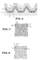
- FIG. 6 is a view showing a first modification of the invention and corresponding to FIG. 1 ;
- FIG. 7 is a view showing a second modification of the invention and corresponding to FIG. 3 ;
- FIG. 8 is a view showing a third modification of the invention and corresponding to FIG. 3 .
- a plain bearing (corresponding to the sliding member) according to the invention is fabricated in the following manner. First, sintering or casting and rolling are used to provide a bearing alloy layer (sliding alloy layer) on a steel back sheet, and then machining is used to fabricate a plain bearing. In this case, a copper alloy (Cu-23Pb-3Sn) (by mass %) is used for the bearing alloy layer in the embodiment but an aluminum alloy will do.
- a copper alloy Cu-23Pb-3Sn
- FIGS. 1 to 3 schematically show a state, in which a plain bearing is finished.
- the intermediate layer 3 is made of Ni or a Ni alloy to have a thickness of 1 to 5 ⁇ m. Thereafter, electroplating is used to provide a soft layer 4 on the intermediate layer 3 in a manner to fill up the recesses 2 .
- the soft layer 4 is made of pure Sn, or a Sn alloy containing Cu.
- protrudent intermetallic compounds 5 (see FIG. 2 ) is formed between the intermediate layer 3 and the soft layer 4 to extend like columns from the intermediate layer 3 into the soft layer 4 .
- the protrudent intermetallic compounds 5 is composed of an intermetallic compound of Sn—Cu—Ni and Sn—Cu.
- the reference numeral 5 a denotes a Sn—Cu intermetallic compound that has not grown into the protrudent intermetallic compounds 5 .
- the protrudent intermetallic compounds 5 is composed of an intermetallic compound of Sn—Ni.
- FIGS. 4A and 4B show the formation condition of the protrudent intermetallic compounds and found the following matters. That is, it has been found that in order to facilitate formation of the protrudent intermetallic compounds, heat treatment at high temperatures, heat treatment over a long period of time, and the like are preferably performed and there is a relationship as shown in FIGS. 4A and 4B .
- FIG. 4A shows the case where the soft layer contains a small quantity of Cu (the soft layer (Sn-3Cu)/the intermediate layer (Ni)/the bearing alloy layer (Cu alloy)), and
- FIG. 4B shows the case where the soft layer contains a large quantity of Cu (the soft layer (Sn-10Cu)/the intermediate layer (Ni)/the bearing alloy layer (Cu alloy)) (by mass %).
- the present inventors have found that formation of the protrudent intermetallic compounds can be promoted by increasing a quantity of Cu in the soft layer. Also, it has been found that when a quantity of Cu is increased in an area near to the intermediate layer, making the intermetallic compound protrudent can be consequently promoted.
- the present inventors have enabled clarifying conditions for promoted formation of the protrudent intermetallic compounds that constitutes a feature of the invention.
- machining is again used to scrape an uppermost surface portion to bring about a state, in which the bearing alloy layer 1 , the soft layer 4 with the recesses 2 , and the intermediate layer 3 are mixed on a sliding surface (an upper surface in FIG. 1 ) as shown in FIG. 1 .
- a plain bearing is finished.
- the comparative specimen Nos. 1 to 3 are different in conditions of heat treatment after the formation of the soft layer from the invention speimens, for which comparative specimens the heat treatment was performed under the condition of 130° C. ⁇ 1 Hr and in which comparative specimens there was not formed any protrudent intermetallic compounds extending like column from the intermediate layer into the soft layer. Also, the specimens, in which an area ratio of the recesses 2 to the sliding surface was 70%, were used in the tests.
- % in the soft layer represents mass %.
- a soft layer in the comparative specimen No. 1 was made of a Pb alloy containing Cu while soft layers in the remaining comparative specimen Nos. 2 and 3, and the invention specimen Nos. 1 to 9 were made of a Sn alloy containing Cu.
- the soft layers in the invention specimen Nos. 2 and 7 out of the invention specimen Nos. 1 to 9 contained Ag in addition to Cu, and the soft layer in the invention specimen No. 6 contained Sb.
- the cavitation tests were carried out under conditions indicated in following Table 2 with the use of a testing machine shown in FIG. 5 .
- the cavitation tests were carried out such that a test piece 8 was set in a water tank 7 with water 6 stored therein, a horn 9 for generation of supersonic waves applied supersonic waves (19000 Hz) to a sliding surface of the test piece 8 in the water for 3 minutes with a predetermined clearance (0.5 mm) therebetween, as shown in FIG. 5 and a volumetric reduction before and after the test was measured.
- the measured volumetric reduction is shown in the column of the cavitation test in Table 1.
- the volumetric reduction in the cavitation tests was 1.1 mm 3 or more for the comparative specimen Nos. 1 to 3 while it was 0.7 mm 3 or less for the invention specimen Nos. 1 to 9, and thus it could be confirmed that the invention specimen Nos. 1 to 9 were excellent in cavitation resistance. This is thought to be largely attributed to an anchoring effect produced by protrudent intermetallic compounds that extend like columns from the intermediate layer.
- specimen Nos. 1 to 9 will be examined. While all the soft layers in specimen Nos. 1, 3 to 5, 8, 9 are made of a Sn—Cu alloy, specimen Nos. 3 to 5, 8, 9 having a Cu content of 15 mass % or less are small in volumetric reduction as compared with specimen No. 1 having a Cu content of 25 mass %. In terms of cavitation resistance, a Cu content of less than 25 mass % is preferable, 20 mass % or less is more preferable, and 5 to 15 mass % is furthermore preferable.
- specimen No. 7 having a Ag content of 2 mass % is small in volumetric reduction as compared with specimen No. 2 having a Ag content of 15 mass %.
- a Ag content of less than 15 mass % is preferable, 10 mass % or less is more preferable, and 5 mass % or less is furthermore preferable.
- FIG. 6 shows a first modification of the invention that is different from the embodiment in the following point. That is, while according to the embodiment described above a structure, in which the bearing alloy layer 1 , the soft layer 4 with the recesses 2 , and the intermediate layer 3 are mixed on a sliding surface (an upper surface in FIG. 1 ), is provided by machining of the uppermost surface portion after the heat treatment, the first modification provides a structure, in which machining of the uppermost surface portion is omitted and all the surface is covered by the soft layer. This structure is effective in case of aiming at an improvement in initial conformability.
- FIG. 7 shows a second modification of the invention that is different from the embodiment in the following point. That is, while according to the embodiment the recesses 2 are formed to be grooved, the second modification provides a structure, in which a multiplicity of recesses 10 having an independent, rectangular configuration as viewed from above are formed, an intermediate layer 3 (see FIG. 1 ) is provided on internal surfaces of the respective recesses 10 , and a soft layer 4 is provided on the intermediate layer 3 .
- FIG. 8 shows a third modification of the invention that is different from the second modification described above in the following point. That is, according to the third modification, exposed portions 11 of a bearing alloy layer 1 are left in the form of a rectangle, a continuous recess 12 is formed around the exposed portions, an intermediate layer 3 (see FIG. 1 ) is provided on an internal surface of the recess 12 , and a soft layer 4 is provided on the intermediate layer 3 .
- the invention is not limited to the embodiment and the first to third modifications but afford modification or extension as follows.
- an uppermost surface layer of the order of 1 to 10 ⁇ m may be provided on an uppermost surface of a sliding surface in a plain bearing.
- a method of forming recesses 2 , 10 , 12 can adopt, in addition to machining (boring), a chemical treatment comprised by a combination of masking and etching, a physical treatment comprised by a combination of masking and shot blasting, or laser processing.
- the soft layer 4 can be of a double-layered plating structure such that when the soft layer 4 is provided, a Sn—Cu alloy (for example, Sn-10% Cu) having a high Cu concentration is first coated and thereafter a Sn—Cu alloy (for example, Sn-4%Cu) having a low Cu concentration is coated thereon, or the soft layer 4 can be structured to have a component inclination that is increased in Cu concentration toward the intermediate layer 3 .
- a Sn—Cu alloy for example, Sn-10% Cu
- Sn—Cu alloy for example, Sn-4%Cu
- the invention is also applicable to other sliding members than plain bearings.
Landscapes
- Engineering & Computer Science (AREA)
- General Engineering & Computer Science (AREA)
- Mechanical Engineering (AREA)
- Sliding-Contact Bearings (AREA)
- Electroplating Methods And Accessories (AREA)
Applications Claiming Priority (2)
| Application Number | Priority Date | Filing Date | Title |
|---|---|---|---|
| JP2003187727A JP3958719B2 (ja) | 2003-06-30 | 2003-06-30 | 摺動部材 |
| JP2003-187727 | 2003-06-30 |
Publications (2)
| Publication Number | Publication Date |
|---|---|
| US20040264820A1 US20040264820A1 (en) | 2004-12-30 |
| US7431507B2 true US7431507B2 (en) | 2008-10-07 |
Family
ID=32844732
Family Applications (1)
| Application Number | Title | Priority Date | Filing Date |
|---|---|---|---|
| US10/862,359 Expired - Fee Related US7431507B2 (en) | 2003-06-30 | 2004-06-08 | Sliding member |
Country Status (5)
| Country | Link |
|---|---|
| US (1) | US7431507B2 (de) |
| JP (1) | JP3958719B2 (de) |
| KR (1) | KR20050002597A (de) |
| DE (1) | DE102004030017C5 (de) |
| GB (1) | GB2404228B (de) |
Cited By (3)
| Publication number | Priority date | Publication date | Assignee | Title |
|---|---|---|---|---|
| US20130309522A1 (en) * | 2011-02-15 | 2013-11-21 | Kabushiki Kaisha Kobe Seiko Sho (Kobe Steel, Ltd.) | Sliding member and method for manufacturing the same |
| US20140119682A1 (en) * | 2011-06-20 | 2014-05-01 | Oiles Corporation | Thrust sliding bearing |
| US20210332852A1 (en) * | 2020-04-27 | 2021-10-28 | Delavan Inc. | Bearing system |
Families Citing this family (15)
| Publication number | Priority date | Publication date | Assignee | Title |
|---|---|---|---|---|
| JP2005023344A (ja) * | 2003-06-30 | 2005-01-27 | Daido Metal Co Ltd | 摺動部材 |
| JP4646721B2 (ja) * | 2005-07-22 | 2011-03-09 | 株式会社神戸製鋼所 | ヒューズ用めっき付き銅合金材及びその製造方法 |
| JP4725229B2 (ja) * | 2005-07-28 | 2011-07-13 | トヨタ自動車株式会社 | 組合せ摺動部材、及びこれを用いた内燃機関及びすべり軸受機構 |
| US7942583B2 (en) | 2005-09-27 | 2011-05-17 | Jtekt Corporation | Rolling bearing cage, ball bearing and roller bearing |
| JP4942972B2 (ja) * | 2005-09-27 | 2012-05-30 | 株式会社ジェイテクト | 玉軸受用保持器および玉軸受 |
| DE102007047007A1 (de) * | 2007-10-01 | 2009-04-09 | Tyco Electronics Amp Gmbh | Elektrisches Kontaktelement und ein Verfahren zum Herstellen desselben |
| DE112008002866A5 (de) * | 2007-11-09 | 2010-12-16 | Miba Gleitlager Gmbh | Lagerelement |
| JP2009228776A (ja) * | 2008-03-21 | 2009-10-08 | Mitsubishi Heavy Ind Ltd | 軸受 |
| AT509111B1 (de) * | 2009-12-10 | 2011-09-15 | Miba Gleitlager Gmbh | Gleitschicht |
| AT509112B1 (de) * | 2009-12-10 | 2011-09-15 | Miba Gleitlager Gmbh | Gleitschicht |
| AT510190B1 (de) | 2010-07-30 | 2012-05-15 | Miba Gleitlager Gmbh | Verfahren zum herstellen eines mehrschichtigen gleitlagers |
| JP5981097B2 (ja) | 2011-05-25 | 2016-08-31 | 大同メタル工業株式会社 | Al合金軸受及びAl合金軸受の製造方法 |
| AT511434B1 (de) * | 2012-01-16 | 2012-12-15 | Miba Gleitlager Gmbh | Gleitlager |
| JP5897934B2 (ja) * | 2012-03-02 | 2016-04-06 | 大同メタル工業株式会社 | 摺動材料および軸受装置 |
| US10941767B2 (en) * | 2018-03-29 | 2021-03-09 | Hamilton Sunstrand Corporation | Hybrid pump bearing for contamination resistance |
Citations (14)
| Publication number | Priority date | Publication date | Assignee | Title |
|---|---|---|---|---|
| JPS57144313A (en) | 1981-02-06 | 1982-09-06 | Miba Gleitlager Ag | Thrust bearing applying heavy load |
| DE8206353U1 (de) | 1982-03-06 | 1983-05-05 | Glyco-Metall-Werke Daelen & Loos Gmbh, 6200 Wiesbaden | Gleitlagerschale mit gleitschicht aus weissmetall-legierung auf zinn-basis |
| US4561787A (en) | 1984-02-27 | 1985-12-31 | Miba Gleitlager Aktiengesellschaft | Composite sliding surface bearing |
| GB2216199A (en) | 1988-02-23 | 1989-10-04 | Metal Leve Sa | Bearing for internal combustion engines |
| JPH02142921A (ja) | 1988-11-21 | 1990-06-01 | Komatsu Ltd | 内燃機関用すべり軸受 |
| US5000586A (en) | 1988-02-23 | 1991-03-19 | Metal Leve S.A. Industria E. Commercio | Sliding bearing |
| GB2256903A (en) | 1991-06-11 | 1992-12-23 | Honda Motor Co Ltd | Slide bearing |
| JPH06280090A (ja) | 1993-03-26 | 1994-10-04 | Taiho Kogyo Co Ltd | すべり軸受材料 |
| JPH07133825A (ja) | 1993-11-08 | 1995-05-23 | Taiho Kogyo Co Ltd | すべり軸受 |
| EP0758721A1 (de) | 1995-03-01 | 1997-02-19 | Taiho Kogyo Co., Ltd. | Gleitlager |
| JP2000345389A (ja) | 1999-04-28 | 2000-12-12 | Federal Mogul Weisbaden Gmbh | 摺動部材用の多層材料およびこの材料を作製する方法 |
| EP1092885A2 (de) | 1999-09-29 | 2001-04-18 | Daido Metal Company Ltd. | Gleitlager |
| JP2002310158A (ja) | 2001-04-09 | 2002-10-23 | Daido Metal Co Ltd | 複層摺動材料 |
| US6770383B2 (en) | 2001-01-19 | 2004-08-03 | The Furukawa Electric Co., Ltd. | Plated material, method of producing same, and electrical/electronic part using same |
Family Cites Families (2)
| Publication number | Priority date | Publication date | Assignee | Title |
|---|---|---|---|---|
| JPH05321936A (ja) * | 1992-05-13 | 1993-12-07 | Hitachi Constr Mach Co Ltd | 固体潤滑剤埋込型軸受およびその製造方法 |
| DE19963385C1 (de) * | 1999-12-28 | 2001-01-25 | Federal Mogul Wiesbaden Gmbh | Schichtverbundwerkstoff für Gleitlager |
-
2003
- 2003-06-30 JP JP2003187727A patent/JP3958719B2/ja not_active Expired - Fee Related
-
2004
- 2004-06-08 US US10/862,359 patent/US7431507B2/en not_active Expired - Fee Related
- 2004-06-22 DE DE102004030017A patent/DE102004030017C5/de not_active Expired - Fee Related
- 2004-06-29 GB GB0414561A patent/GB2404228B/en not_active Expired - Fee Related
- 2004-06-29 KR KR1020040049244A patent/KR20050002597A/ko not_active Application Discontinuation
Patent Citations (16)
| Publication number | Priority date | Publication date | Assignee | Title |
|---|---|---|---|---|
| JPS57144313A (en) | 1981-02-06 | 1982-09-06 | Miba Gleitlager Ag | Thrust bearing applying heavy load |
| AT369145B (de) | 1981-02-06 | 1982-12-10 | Miba Gleitlager Ag | Hochbelastbares gleitlager |
| US4400099A (en) | 1981-02-06 | 1983-08-23 | Miba Gleitlager Aktiengesellschaft | Sliding surface bearing for heavy loads |
| DE8206353U1 (de) | 1982-03-06 | 1983-05-05 | Glyco-Metall-Werke Daelen & Loos Gmbh, 6200 Wiesbaden | Gleitlagerschale mit gleitschicht aus weissmetall-legierung auf zinn-basis |
| US4561787A (en) | 1984-02-27 | 1985-12-31 | Miba Gleitlager Aktiengesellschaft | Composite sliding surface bearing |
| GB2216199A (en) | 1988-02-23 | 1989-10-04 | Metal Leve Sa | Bearing for internal combustion engines |
| US5000586A (en) | 1988-02-23 | 1991-03-19 | Metal Leve S.A. Industria E. Commercio | Sliding bearing |
| JPH02142921A (ja) | 1988-11-21 | 1990-06-01 | Komatsu Ltd | 内燃機関用すべり軸受 |
| GB2256903A (en) | 1991-06-11 | 1992-12-23 | Honda Motor Co Ltd | Slide bearing |
| JPH06280090A (ja) | 1993-03-26 | 1994-10-04 | Taiho Kogyo Co Ltd | すべり軸受材料 |
| JPH07133825A (ja) | 1993-11-08 | 1995-05-23 | Taiho Kogyo Co Ltd | すべり軸受 |
| EP0758721A1 (de) | 1995-03-01 | 1997-02-19 | Taiho Kogyo Co., Ltd. | Gleitlager |
| JP2000345389A (ja) | 1999-04-28 | 2000-12-12 | Federal Mogul Weisbaden Gmbh | 摺動部材用の多層材料およびこの材料を作製する方法 |
| EP1092885A2 (de) | 1999-09-29 | 2001-04-18 | Daido Metal Company Ltd. | Gleitlager |
| US6770383B2 (en) | 2001-01-19 | 2004-08-03 | The Furukawa Electric Co., Ltd. | Plated material, method of producing same, and electrical/electronic part using same |
| JP2002310158A (ja) | 2001-04-09 | 2002-10-23 | Daido Metal Co Ltd | 複層摺動材料 |
Cited By (6)
| Publication number | Priority date | Publication date | Assignee | Title |
|---|---|---|---|---|
| US20130309522A1 (en) * | 2011-02-15 | 2013-11-21 | Kabushiki Kaisha Kobe Seiko Sho (Kobe Steel, Ltd.) | Sliding member and method for manufacturing the same |
| US9976209B2 (en) * | 2011-02-15 | 2018-05-22 | Kobe Steel, Ltd. | Sliding member and method for manufacturing the same |
| US20140119682A1 (en) * | 2011-06-20 | 2014-05-01 | Oiles Corporation | Thrust sliding bearing |
| US9062708B2 (en) * | 2011-06-20 | 2015-06-23 | Oiles Corporation | Thrust sliding bearing |
| US20210332852A1 (en) * | 2020-04-27 | 2021-10-28 | Delavan Inc. | Bearing system |
| US11598374B2 (en) * | 2020-04-27 | 2023-03-07 | Collins Engine Nozzles, Inc. | Bearing system |
Also Published As
| Publication number | Publication date |
|---|---|
| DE102004030017B4 (de) | 2006-07-06 |
| US20040264820A1 (en) | 2004-12-30 |
| DE102004030017A1 (de) | 2005-02-24 |
| GB2404228B (en) | 2005-07-27 |
| GB2404228A (en) | 2005-01-26 |
| JP2005023345A (ja) | 2005-01-27 |
| DE102004030017C5 (de) | 2008-12-18 |
| GB0414561D0 (en) | 2004-08-04 |
| JP3958719B2 (ja) | 2007-08-15 |
| KR20050002597A (ko) | 2005-01-07 |
Similar Documents
| Publication | Publication Date | Title |
|---|---|---|
| US7431507B2 (en) | Sliding member | |
| US5911513A (en) | Sliding bearing of copper-based alloy | |
| US6334914B2 (en) | Copper alloy sliding material | |
| US6194087B1 (en) | Composite multilayer bearing material | |
| US4937149A (en) | Overlay alloy used for a surface layer of sliding material, sliding material having a surface layer comprising said alloy and the manufacturing method of the sliding material | |
| US5056936A (en) | Multilayer plain bearing | |
| JPH04504595A (ja) | 改善された滑り特性を有する高耐摩耗性オーバーレイおよびその製造方法 | |
| US20030048961A1 (en) | Sliding member | |
| US5666644A (en) | Multilayered end bearing | |
| US5334460A (en) | CU-PB system alloy composite bearing having overlay | |
| US7153591B2 (en) | Sliding member | |
| GB2285839A (en) | Slide bearing material | |
| US7063897B2 (en) | Slide member | |
| US3403010A (en) | Multilayer bearing having a base of steel and a surface layer of a lead alloy | |
| GB2285266A (en) | Cu-Pb alloy bearing | |
| GB2375801A (en) | Multi-layered sliding material of tin-copper | |
| JPH06322462A (ja) | 耐腐蝕性に優れた銅鉛軸受合金材料及びその製造方法 | |
| JPS6096741A (ja) | すべり軸受およびその製造方法 | |
| US7174637B2 (en) | Bearings | |
| JPS604918B2 (ja) | 内燃機関の軸受およびその製造方法 | |
| JP2003090343A (ja) | 多層摺動材料 | |
| US3969084A (en) | Copper-base bearing material containing corrosion-resistant lead alloy | |
| JP2852521B2 (ja) | 内燃機関用すべり軸受 | |
| US20120064358A1 (en) | Slide member | |
| US6974257B2 (en) | Dynamic pressure bearing |
Legal Events
| Date | Code | Title | Description |
|---|---|---|---|
| AS | Assignment |
Owner name: DAIDO METAL COMPANY LTD., JAPAN Free format text: ASSIGNMENT OF ASSIGNORS INTEREST;ASSIGNORS:TSUJI, HIDEO;FUJITA, MASAHITO;KAWAKAMI, NAOHISA;AND OTHERS;REEL/FRAME:020429/0279 Effective date: 20040525 |
|
| CC | Certificate of correction | ||
| FPAY | Fee payment |
Year of fee payment: 4 |
|
| REMI | Maintenance fee reminder mailed | ||
| LAPS | Lapse for failure to pay maintenance fees | ||
| STCH | Information on status: patent discontinuation |
Free format text: PATENT EXPIRED DUE TO NONPAYMENT OF MAINTENANCE FEES UNDER 37 CFR 1.362 |
|
| FP | Lapsed due to failure to pay maintenance fee |
Effective date: 20161007 |