US7401463B2 - Heat shield for internal combustion engine exhaust system - Google Patents
Heat shield for internal combustion engine exhaust system Download PDFInfo
- Publication number
- US7401463B2 US7401463B2 US10/661,493 US66149303A US7401463B2 US 7401463 B2 US7401463 B2 US 7401463B2 US 66149303 A US66149303 A US 66149303A US 7401463 B2 US7401463 B2 US 7401463B2
- Authority
- US
- United States
- Prior art keywords
- heat shield
- exhaust system
- shield plate
- section
- internal combustion
- Prior art date
- Legal status (The legal status is an assumption and is not a legal conclusion. Google has not performed a legal analysis and makes no representation as to the accuracy of the status listed.)
- Expired - Fee Related, expires
Links
Images


Classifications
-
- F—MECHANICAL ENGINEERING; LIGHTING; HEATING; WEAPONS; BLASTING
- F01—MACHINES OR ENGINES IN GENERAL; ENGINE PLANTS IN GENERAL; STEAM ENGINES
- F01N—GAS-FLOW SILENCERS OR EXHAUST APPARATUS FOR MACHINES OR ENGINES IN GENERAL; GAS-FLOW SILENCERS OR EXHAUST APPARATUS FOR INTERNAL COMBUSTION ENGINES
- F01N13/00—Exhaust or silencing apparatus characterised by constructional features ; Exhaust or silencing apparatus, or parts thereof, having pertinent characteristics not provided for in, or of interest apart from, groups F01N1/00 - F01N5/00, F01N9/00, F01N11/00
- F01N13/14—Exhaust or silencing apparatus characterised by constructional features ; Exhaust or silencing apparatus, or parts thereof, having pertinent characteristics not provided for in, or of interest apart from, groups F01N1/00 - F01N5/00, F01N9/00, F01N11/00 having thermal insulation
-
- F—MECHANICAL ENGINEERING; LIGHTING; HEATING; WEAPONS; BLASTING
- F16—ENGINEERING ELEMENTS AND UNITS; GENERAL MEASURES FOR PRODUCING AND MAINTAINING EFFECTIVE FUNCTIONING OF MACHINES OR INSTALLATIONS; THERMAL INSULATION IN GENERAL
- F16L—PIPES; JOINTS OR FITTINGS FOR PIPES; SUPPORTS FOR PIPES, CABLES OR PROTECTIVE TUBING; MEANS FOR THERMAL INSULATION IN GENERAL
- F16L59/00—Thermal insulation in general
- F16L59/08—Means for preventing radiation, e.g. with metal foil
-
- F—MECHANICAL ENGINEERING; LIGHTING; HEATING; WEAPONS; BLASTING
- F01—MACHINES OR ENGINES IN GENERAL; ENGINE PLANTS IN GENERAL; STEAM ENGINES
- F01N—GAS-FLOW SILENCERS OR EXHAUST APPARATUS FOR MACHINES OR ENGINES IN GENERAL; GAS-FLOW SILENCERS OR EXHAUST APPARATUS FOR INTERNAL COMBUSTION ENGINES
- F01N2470/00—Structure or shape of gas passages, pipes or tubes
- F01N2470/08—Gas passages being formed between the walls of an outer shell and an inner chamber
Definitions
- the present invention relates to a heat shield for an internal combustion engine exhaust system in which the heat shield can have a simple two-piece structure.
- FIG. 4 of Japanese Patent Laid-open No. Sho. 54-120277 shows an exhaust pipe in which an outer pipe a and an inner pipe b, that is inserted into the outer pipe a, are welded to a flange 4 at end sections of the respective outer pipe a and inner pipe b, and then curving processing is carried out using a roller 11 of a rotary bender B.
- the object of the present invention is therefore to provide a heat shield for an internal combustion engine exhaust system that enables the heat shield to have a two-part structure, and that also suppresses cost increases.
- a first aspect of the present invention provides a heat shield for an internal combustion engine exhaust system for supporting a heat shield plate on an exhaust system member extending from an exhaust port of an internal combustion engine, via a support member such as a band member.
- the heat shield includes a first heat shield plate for covering all around a curved section of the exhaust system member which is provided in the vicinity of an exhaust port, and a second heat shield plate for covering above a straight section of the exhaust system member which connects to the curved section.
- a two-part exhaust pipe is used in the vicinity of the engine in order to handle temperature.
- a first heat shield plate for covering all around the exhaust system member to a curved section in the vicinity of the internal combustion engine using a support member such as a band member, it becomes practical to form the first heat shield plate as a two-part structure since the exhaust system member is formed as one piece. With this configuration, it is possible to exhibit heat-shielding effects and to reduce the cost.
- a small diameter section is provided on an end section of the first heat shield plate, and overlapping an end section of the second heat shield plate with this small diameter section via a gap.
- FIG. 1 is a side elevation of a vehicle fitted with an engine provided with the exhaust system heat shield of the present invention
- FIG. 2 is a plan view of a vehicle relating to the present invention
- FIG. 3 is a rear view of a vehicle relating to the present invention.
- FIG. 4 is a plan view of an internal combustion engine exhaust system relating to the present invention.
- FIG. 5 is a plan view showing a U-shaped exhaust pipe and a heat shield plate relating to the present invention
- FIGS. 6( a ) and ( b ) are explanatory drawings of a U-shaped pipe relating to the present invention.
- FIG. 7 is a cross section along line 7 - 7 in FIG. 5 ;
- FIG. 8 is a cross section along line 8 - 8 in FIG. 5 ;
- FIG. 9 is a cross section along line 9 - 9 in FIG. 6( a );
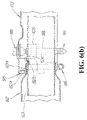
- FIG. 10 is a cross section along line 10 - 10 in FIG. 6( a );
- FIG. 11 is a perspective drawing showing essential parts of a heat shield attachment fixture relating to the present invention.
- FIG. 12 is an operational drawing showing operation of the first and second heat shield plates relating to the present invention.
- FIG. 13 is a cross sectional drawing showing a comparative example of a band member for attaching a heat shield plate to an exhaust pipe.
- FIG. 1 is a side elevation of a vehicle fitted with an engine provided with the exhaust system heat shield of the present invention.
- the vehicle 10 is an all-terrain vehicle having a handlebar post 12 attached to a front part of a vehicle frame 11 , a lower front end of the handlebar post 12 joined to left and right front wheels 13 , 14 (only the near side front wheel 13 is shown in the drawing), and a handlebar 15 attached to an upper end of the handlebar post 12 .
- the vehicle 10 also includes a power unit 18 comprising an engine 16 and a transmission 17 fitted into the middle of the vehicle frame 11 , and rear wheels 21 , 22 (only the near side rear wheel 21 is shown in the drawing) driven by the power unit 18 together with the front wheels 13 , 14 are arranged at a rear part of the vehicle frame 11 .
- FIG. 1 also shows a front guard 31 for protecting the vehicle front surface, headlamps 32 , 32 (only the nearside headlamp 32 is shown), are shock absorbers 33 , 33 for the front wheels 13 , 14 (only the nearside shock absorber 33 is shown), a fuel tank 34 attached to the vehicle frame 11 , an air duct 35 for supplying air to high temperature parts of the engine 16 , an oil cooler 36 , a shroud 37 enclosing a fan for the oil cooler 36 , and an exhaust unit 38 connected to the front of the engine 16 and extending in a curved manner towards the rear.
- a carburetor 40 connected to a rear part of the engine 16 , an air cleaner unit 41 connected to a rear part of the carburetor 40 , shock 42 , 42 absorbers for the rear wheels 21 , 22 (only the near side shock absorber 42 is shown), a rear carrier 43 on which luggage is placed, front fenders 44 , 44 for covering upper and upper rear parts of the front wheels 13 , 14 (only the nearside fender 44 is shown), steps 45 , 45 on which a driver places their feet (only the near side step 45 is shown), rear fenders 46 , 46 for covering front and upper parts of the rear wheels 21 , 22 (only the nearside fender 46 is shown), and a seat 47 .
- FIG. 2 is a plan view of a vehicle relating to the present invention, and shows left and right main frames 55 , 55 constituting part of the vehicle frame 11 arranged in the center of the vehicle and extending longitudinally, the power unit 18 , air duct 35 for cooling the engine and main air cleaner 56 , constituting the air cleaner unit 41 , arranged between these main frames 55 , 55 , the front end of the air duct 35 being almost the same width as the main frames 55 , 55 , and the exhaust unit 38 bent in a U-shape from the engine 16 to extend towards the rear.
- the exhaust unit 38 is made up of a U-shaped exhaust pipe 63 that curves in a U-shape, a middle exhaust pipe 64 connecting to a rear part of the U-shaped exhaust pipe 63 , and a silencer 65 attached to a rear part of the middle exhaust pipe 64 , and as shown in FIG. 1 , the silencer 65 is attached to the rear part of one of the main frames 55 .
- the air cleaner unit 41 comprises the main air cleaner 56 connected to the carburetor 40 , and a sub air cleaner 67 connected to a rear part of the main air cleaner 56 .
- the main air cleaner 56 and the sub air cleaner 67 are arranged side by side in the longitudinal direction of the vehicle, and also, the sub air cleaner 67 is arranged outside one of the main frames 55 and inside the rear wheel 22 , with the main air cleaner 56 attached to the main frames 55 , 55 and a rear part of the sub air cleaner 67 being attached to one of the main frames 55 .
- FIG. 3 is a rear view of a vehicle relating to the present invention, and shows left and right upper sections of the main air cleaner 56 of the air cleaner unit 41 respectively attached to the main frames 55 , 55 using attachment brackets 71 , 71 , and a sub air cleaner 67 connected to the rear of the main air cleaner 56 arranged in a space at the inner side of the rear wheel 22 .
- FIG. 3 also shows a silencer heat shield plate 72 for covering an upper part and side part of a silencer 65 , tail lamps 73 , 73 , a final reduction gear 74 , rear wheels 21 , 22 , and axles 75 , 76 respectively extending to the left and right rear wheels from the final reduction gear 74 in order to convey drive force to the rear wheels 21 , 22 .
- FIG. 4 is a plan view of an internal combustion engine exhaust system relating to the present invention.
- a U-shaped exhaust pipe 63 is a member connected to an exhaust port 81 a provided in the cylinder head 81 of the engine 16 , and a first heat shield plate 82 for covering a curved section 63 a , and a second heat shield plate 83 for covering a straight section 63 b connected to the curved section 63 a and part of a middle exhaust pipe 64 are attached to the U-shaped exhaust pipe 63 .
- the middle exhaust pipe 64 has a third heat shield plate 84 for covering most of the rear half attached.
- the silencer 65 has the silencer heat shield plate 72 attached to cover almost all above.
- FIG. 5 is a plan view showing a U-shaped exhaust pipe and a heat shield plate relating to the present invention.
- the first heat shield plate 82 is attached to the U-shaped exhaust pipe 63 with band members 86 , 87 , and similarly, the second heat shield plate 83 is attached to the U-shaped exhaust pipe 63 with heat shield plate attachment fixtures 88 , 88 .
- FIG. 6( a ) and FIG. 6( b ) are explanatory drawings of a U-shaped exhaust pipe relating to the present invention, FIG. 6( a ) being a view in the direction of arrow a in FIG. 5 and FIG. 6( b ) being a cross sectional view along line b-b in FIG. 5 .
- the first heat shield plate 82 is made up of an upper plate 91 and a lower plate 92 , with the upper plate 91 and the lower plate 92 being aligned in the vertical direction and then fastened together using a band member 87 .
- a heat shield plate attachment fixtures 88 for attachment of the second heat shield plate 83 are provided with band members 93 , 93 .
- a small diameter section 82 a is formed at the rear end of the first heat shield plate 82 .
- This small diameter section 82 a is attached to the U-shaped exhaust pipe 63 by the band member 86 , and a front end section 83 a of the second heat shield plate 83 is overlapped with the small diameter section 82 a .
- Projecting section 82 b engages with an indented section 63 c of the U-shaped exhaust pipe 63 in order to position the first heat shield plate 82 in the U-shaped exhaust pipe 63 .
- a gap 95 is provided between the small diameter section 82 a and the front-end section 83 a of the second heat shield plate 83 , and C represents the size of the gap 95 .
- FIG. 7 is a cross section along line 7 - 7 in FIG. 5 , and shows an upper projection section 91 a provided on the end of the upper plate 91 (refer to FIG. 6( a )) of the first heat shield plate 82 (refer to FIG. 6( a )), a lower projection section 92 a provided on the end of the lower plate 92 (refer to FIG. 6( a )), and the upper projection section 91 a and lower projection section 92 b being fastened with a band member 86 and attached to the U-shaped exhaust pipe 63 .
- the band member 86 is made up of a band 98 and a tightening section 99 for tightening the band 98 .
- the tightening section 99 is made up of a case 101 , and a bolt 102 rotatably attached to the case 101 .
- the band 98 has one end attached to the case 101 , and a plurality of slits (not shown) substantially orthogonal to the longitudinal direction of the band 98 provided on the other end.
- the bolt 102 has an external thread (not shown), and this external thread engages with the slits of the band 98 inside the case 101 .
- FIG. 8 is a cross section along line 8 - 8 in FIG. 5 , and shows an upper plate 91 and a lower plate 92 , respectively having a cross-section of a half-cut tube, fastened by the band member 87 , giving the first heat shield plate 82 a two-part structure, which surrounds the curved section 63 a of the U-shaped exhaust pipe 63 .
- the band member 87 is different from the band member 86 by only the length of the band 103 , and the remaining structure is the same.
- Flanges 91 b , 91 b are provided on the upper plate 91
- flanges 92 b , 92 b are provided on the lower plate 92 .
- FIG. 9 is a cross section along line 9 - 9 in FIG. 6( a ), and shows the first heat shield plate 82 positioned on the U-shaped exhaust pipe 63 by aligning the projecting section 82 b of the first heat shield plate 82 with the indented section 63 c of the U-shaped exhaust pipe 63 , and covering above and to both sides of a section where the U-shaped exhaust pipe 63 and the first heat shield plate 82 are aligned with the second heat shield plate 83 .
- the first heat shield plate 82 is provided with notched sections 82 c , 82 c in a small diameter section 82 a , being end sections, which constitute a structure for preventing warping due to heat.
- FIG. 10 is a cross section along line 10 - 10 in FIG. 6( a ), and shows the second heat shield plate 83 attached to a straight section 63 b of the U-shaped exhaust pipe 63 with heat shield attachment fixtures 88 .
- the heat shield attachment fixtures 88 comprise a socket fixture 105 for receiving the second heat shield plate 83 , a bolt 107 for fixing the second heat shield plate 83 to the socket fixture 105 by screwing into a nut 106 attached to the socket fixture 105 , and the band member 86 for fixing the socket fixture 105 to the U-shaped exhaust pipe 63 . Also shown is a washer 108 .
- the band member 86 can move the tightening section 99 to a desired position of the U-shaped exhaust pipe 63 , which means that it is possible to be located at a place that is not exposed to the outside, taking into account a place where the tightening section will not interfere with other components and also the general appearance.
- FIG. 11 is a perspective drawing showing essential parts of a heat shield attachment fixture relating to the present invention.
- the socket fixture 105 is made up of a receiving section 111 for receiving the second heat shield plate, and feet sections 112 , 112 extending downwards from both ends of the receiving section 111 .
- a bolt hole 11 a is formed in the receiving section 111 for the bolt to pass through
- the feet sections 112 comprise a vertical section 112 a and an arced section 112 b
- band passing holes 112 c are formed by sections where the feet sections 112 a and the arced sections 112 b meet, for passing the band 98 through. As shown in FIG.
- the arced sections 112 b , 112 b press against the U-shaped exhaust pipe 63 , and these arced sections 112 b , 112 b are tightened up on the U-shaped exhaust pipe 63 by the band member 86 .
- FIG. 12 is an operational drawing showing operation of the first and second heat shield plates relating to the present invention.
- FIG. 13 is a cross sectional drawing showing a comparative example of a band member for attaching a heat shield plate to an exhaust pipe (refer to the partial cross section, for example, of Japanese Utility Model Laid-open No. Hei. 2-40924), and shows an exhaust pipe 201 enclosed by support bands 202 , 203 , respectively bent out sections 204 , 205 formed on these support bands 202 , 203 , bent out sections 207 , 207 formed on a heat shield plate 206 , and an exhaust pipe 201 attached to the heat shield plate 206 by overlapping the bent out sections 204 , 205 , 207 , 207 and fastening together using attachment bolts 211 , 211 and nuts 212 , 212 .
- the present invention firstly provides a heat shield for an internal combustion engine exhaust system for supporting a first heat shield plate 82 and a second heat shield plate 83 on a U-shaped exhaust pipe 63 extending from an exhaust port 81 a of an engine 16 , via a support member such as band members 86 , 87 .
- the first heat shield plate 82 for covering all around the U-shaped exhaust pipe 63 is provided on a curved section 63 a of the U-shaped exhaust pipe 63 provided in the vicinity of the exhaust port 81 a
- the second heat shield plate 83 for covering above the U-shaped exhaust pipe 63 is provided at a straight section 63 b of the U-shaped exhaust pipe 63 connecting to the curved section 63 a.
- the present invention by providing the first heat shield plate 82 for covering all around the curved section 63 a of the U-shaped exhaust pipe 63 which is in the vicinity of the engine 16 , without using the two-part exhaust pipe as in the related art, because of the U-shaped exhaust pipe 63 , first heat shield plate 82 and band members 86 , 87 , it is possible to easily have a first heat shield plate with a two-part structure that does not require the advanced technology of the related art without carrying out welding or the like, a heat shielding effect is exhibited and it is possible to reduce cost.
- the present invention provides a small diameter section 82 a on the first heat shield plate 82 , and a front end section 83 a of the second heat shield plate 83 is overlapped with this small diameter section 82 a via a gap 95 .
- a gap 95 By overlapping the small diameter section 82 a of the first heat shielding plate with the front end section 83 a of the second heat shield plate 83 via the gap 95 , it is possible for travel wind to enter from the gap 95 into a gap between the U-shaped exhaust pipe 63 and the second heat shield plate 83 . As a result, it is possible to improve the cooling characteristics of the U-shaped exhaust pipe 63 .
- the support members for the band members and heat shield plate attachment fixtures of the present invention can be used for attaching a third heat shield plate to a middle exhaust pipe 64 , and to attach a silencer heat shield plate to a silencer 65 .
- the internal combustion engine exhaust system heat shield includes a first heat shield plate for covering all around the exhaust system members provided on a curved section of the exhaust system members provided in the vicinity of an exhaust port, and a second heat shield plate for covering above the exhaust system members provided at a straight section of the exhaust system members connecting to the curved section.
- the internal combustion engine exhaust system heat shield includes a small diameter section provided on the first heat shield plate, and an end section of the second heat shield plate is overlapped with this small diameter section via a gap. This means that it is possible for travel wind to enter from the gap into a gap between the exhaust system members and the second heat shield plate, and it is possible to improve the cooling characteristics of the exhaust system members.
Applications Claiming Priority (2)
| Application Number | Priority Date | Filing Date | Title |
|---|---|---|---|
| JP2002287988A JP3940053B2 (ja) | 2002-09-30 | 2002-09-30 | 内燃機関排気系の遮熱装置 |
| JP2002-287988 | 2002-09-30 |
Publications (2)
| Publication Number | Publication Date |
|---|---|
| US20040083714A1 US20040083714A1 (en) | 2004-05-06 |
| US7401463B2 true US7401463B2 (en) | 2008-07-22 |
Family
ID=32170865
Family Applications (1)
| Application Number | Title | Priority Date | Filing Date |
|---|---|---|---|
| US10/661,493 Expired - Fee Related US7401463B2 (en) | 2002-09-30 | 2003-09-15 | Heat shield for internal combustion engine exhaust system |
Country Status (2)
| Country | Link |
|---|---|
| US (1) | US7401463B2 (ja) |
| JP (1) | JP3940053B2 (ja) |
Cited By (8)
| Publication number | Priority date | Publication date | Assignee | Title |
|---|---|---|---|---|
| US20060179828A1 (en) * | 2005-02-11 | 2006-08-17 | Bernd Ell | Shielding component, a heat shield in particular |
| US20060277864A1 (en) * | 2005-02-11 | 2006-12-14 | Dieter Hofmann | Structural component, in particular a lubricating component |
| US8215447B1 (en) * | 2010-12-28 | 2012-07-10 | Kawasaki Jukogyo Kabushiki Kaisha | Exhaust device of vehicle and straddle-type four-wheeled vehicle provided with the same |
| US20140174581A1 (en) * | 2012-12-26 | 2014-06-26 | Honda Motor Co., Ltd. | Exhaust pipe cover structure for saddle-ride type vehicle |
| US20150059913A1 (en) * | 2013-09-05 | 2015-03-05 | Scambia Holdings Cyprus Limited | Exhaust pipe |
| US10072787B2 (en) | 2017-02-02 | 2018-09-11 | Honda Motor Co., Ltd. | Clamping system |
| US20200232375A1 (en) * | 2019-01-17 | 2020-07-23 | Honda Motor Co., Ltd. | Muffler with internal gap heat shield |
| US10974783B2 (en) | 2018-08-17 | 2021-04-13 | Harley-Davidson Motor Company Group, LLC | Exhaust shield assembly |
Families Citing this family (14)
| Publication number | Priority date | Publication date | Assignee | Title |
|---|---|---|---|---|
| US7263827B2 (en) * | 2003-04-04 | 2007-09-04 | Honda Motor Co., Ltd. | Exhaust pipe insulator attaching structure for saddle-riding vehicle |
| JP4316390B2 (ja) * | 2004-01-09 | 2009-08-19 | 本田技研工業株式会社 | 不整地走行用鞍乗り型四輪車 |
| JP2006070705A (ja) * | 2004-08-31 | 2006-03-16 | Honda Motor Co Ltd | 車両用エンジンの排気装置 |
| JP2008133823A (ja) * | 2006-10-31 | 2008-06-12 | Yamaha Motor Co Ltd | 車両 |
| KR101316623B1 (ko) | 2011-11-04 | 2013-10-15 | 주식회사 이엔테크 | 배기가스 리시버의 보온 마감재 시공방법 |
| DE102013204732A1 (de) * | 2013-03-18 | 2014-09-18 | Eberspächer Exhaust Technology GmbH & Co. KG | Isolierung |
| KR101383349B1 (ko) | 2013-12-02 | 2014-04-10 | (주)세원물산 | 가이드편이 구비된 차량용 히트프로텍터 |
| FR3014822B1 (fr) * | 2013-12-17 | 2017-02-24 | Peugeot Citroen Automobiles Sa | Panneau de protection sous caisse de vehicule avec evacuation d'eau |
| US9851162B2 (en) * | 2014-08-05 | 2017-12-26 | Air International, Inc. | Cover for heat source |
| US9464557B2 (en) | 2014-11-20 | 2016-10-11 | Ford Global Technologies, Llc | Muffler shield and muffler assembly employing the same |
| US10443440B2 (en) * | 2015-04-09 | 2019-10-15 | United Technologies Corporation | Heat shield, systems and methods |
| US9982579B2 (en) * | 2015-07-07 | 2018-05-29 | United Technologies Corporation | Thermally compliant heatshield |
| US9764697B1 (en) * | 2016-03-18 | 2017-09-19 | Honda Motor Co., Ltd. | Heat shield for a motor vehicle |
| JP6859942B2 (ja) * | 2017-12-19 | 2021-04-14 | トヨタ自動車株式会社 | 内燃機関 |
Citations (13)
| Publication number | Priority date | Publication date | Assignee | Title |
|---|---|---|---|---|
| US3863445A (en) * | 1972-08-04 | 1975-02-04 | Tenneco Inc | Heat shields for exhaust system |
| JPS54120277A (en) | 1978-03-10 | 1979-09-18 | Yamaha Motor Co Ltd | Production of double exhaust pipe |
| US4955193A (en) * | 1989-07-17 | 1990-09-11 | Custom Chrome, Inc. | Adjustable shield for motorcycle exhaust pipe |
| US5419125A (en) * | 1992-09-21 | 1995-05-30 | Calsonic Corporation | Exhaust-gas recombustion system |
| US5816043A (en) * | 1996-01-02 | 1998-10-06 | Acoust-A-Fiber Research And Development, Inc. | Shield encompassing a hot pipe |
| US6026846A (en) * | 1996-01-02 | 2000-02-22 | Acoust-A-Fiber Research & Development, Inc. | Shield encompassing a hot pipe |
| US6438949B1 (en) * | 1999-10-25 | 2002-08-27 | Honda Giken Kogyo Kabushiki Kaisha | Cover member attachment structure |
| US6555070B1 (en) * | 1998-10-05 | 2003-04-29 | Scambia Industrial Developments Ag | Exhaust component and method for producing an exhaust component |
| US20030101719A1 (en) * | 2001-11-30 | 2003-06-05 | Kornel Farkas | Heat shield for an exhaust system of an internal combustion engine |
| US6598389B2 (en) * | 2001-06-12 | 2003-07-29 | Dana Corporation | Insulated heat shield |
| US6797402B2 (en) * | 2001-09-28 | 2004-09-28 | Dana Corporation | Insulated heat shield with waved edge |
| US6910546B2 (en) * | 2001-06-08 | 2005-06-28 | Yamaha Hatsudoki Kabushiki Kaisha | Motorcycle induction system |
| US20050140075A1 (en) * | 2003-12-25 | 2005-06-30 | Sanwa Packing Industry Co., Ltd. | Vibration damping mount and metal heat shield |
-
2002
- 2002-09-30 JP JP2002287988A patent/JP3940053B2/ja not_active Expired - Lifetime
-
2003
- 2003-09-15 US US10/661,493 patent/US7401463B2/en not_active Expired - Fee Related
Patent Citations (13)
| Publication number | Priority date | Publication date | Assignee | Title |
|---|---|---|---|---|
| US3863445A (en) * | 1972-08-04 | 1975-02-04 | Tenneco Inc | Heat shields for exhaust system |
| JPS54120277A (en) | 1978-03-10 | 1979-09-18 | Yamaha Motor Co Ltd | Production of double exhaust pipe |
| US4955193A (en) * | 1989-07-17 | 1990-09-11 | Custom Chrome, Inc. | Adjustable shield for motorcycle exhaust pipe |
| US5419125A (en) * | 1992-09-21 | 1995-05-30 | Calsonic Corporation | Exhaust-gas recombustion system |
| US5816043A (en) * | 1996-01-02 | 1998-10-06 | Acoust-A-Fiber Research And Development, Inc. | Shield encompassing a hot pipe |
| US6026846A (en) * | 1996-01-02 | 2000-02-22 | Acoust-A-Fiber Research & Development, Inc. | Shield encompassing a hot pipe |
| US6555070B1 (en) * | 1998-10-05 | 2003-04-29 | Scambia Industrial Developments Ag | Exhaust component and method for producing an exhaust component |
| US6438949B1 (en) * | 1999-10-25 | 2002-08-27 | Honda Giken Kogyo Kabushiki Kaisha | Cover member attachment structure |
| US6910546B2 (en) * | 2001-06-08 | 2005-06-28 | Yamaha Hatsudoki Kabushiki Kaisha | Motorcycle induction system |
| US6598389B2 (en) * | 2001-06-12 | 2003-07-29 | Dana Corporation | Insulated heat shield |
| US6797402B2 (en) * | 2001-09-28 | 2004-09-28 | Dana Corporation | Insulated heat shield with waved edge |
| US20030101719A1 (en) * | 2001-11-30 | 2003-06-05 | Kornel Farkas | Heat shield for an exhaust system of an internal combustion engine |
| US20050140075A1 (en) * | 2003-12-25 | 2005-06-30 | Sanwa Packing Industry Co., Ltd. | Vibration damping mount and metal heat shield |
Cited By (13)
| Publication number | Priority date | Publication date | Assignee | Title |
|---|---|---|---|---|
| US20060277864A1 (en) * | 2005-02-11 | 2006-12-14 | Dieter Hofmann | Structural component, in particular a lubricating component |
| US7726216B2 (en) * | 2005-02-11 | 2010-06-01 | Elringklinger Ag | Structural component, in particular a lubricating component |
| US7856811B2 (en) * | 2005-02-11 | 2010-12-28 | Elringklinger Ag | Shielding component, a heat shield in particular |
| US20060179828A1 (en) * | 2005-02-11 | 2006-08-17 | Bernd Ell | Shielding component, a heat shield in particular |
| US8215447B1 (en) * | 2010-12-28 | 2012-07-10 | Kawasaki Jukogyo Kabushiki Kaisha | Exhaust device of vehicle and straddle-type four-wheeled vehicle provided with the same |
| US9573459B2 (en) * | 2012-12-26 | 2017-02-21 | Honda Motor Co., Ltd. | Exhaust pipe cover structure for saddle-ride type vehicle |
| US20140174581A1 (en) * | 2012-12-26 | 2014-06-26 | Honda Motor Co., Ltd. | Exhaust pipe cover structure for saddle-ride type vehicle |
| US20150059913A1 (en) * | 2013-09-05 | 2015-03-05 | Scambia Holdings Cyprus Limited | Exhaust pipe |
| US9784167B2 (en) * | 2013-09-05 | 2017-10-10 | Bosal Emission Control Systems Nv | Exhaust pipe |
| US10072787B2 (en) | 2017-02-02 | 2018-09-11 | Honda Motor Co., Ltd. | Clamping system |
| US10974783B2 (en) | 2018-08-17 | 2021-04-13 | Harley-Davidson Motor Company Group, LLC | Exhaust shield assembly |
| US20200232375A1 (en) * | 2019-01-17 | 2020-07-23 | Honda Motor Co., Ltd. | Muffler with internal gap heat shield |
| US10900407B2 (en) * | 2019-01-17 | 2021-01-26 | Honda Motor Co., Ltd. | Muffler with internal gap heat shield |
Also Published As
| Publication number | Publication date |
|---|---|
| US20040083714A1 (en) | 2004-05-06 |
| JP3940053B2 (ja) | 2007-07-04 |
| JP2004124767A (ja) | 2004-04-22 |
Similar Documents
| Publication | Publication Date | Title |
|---|---|---|
| US7401463B2 (en) | Heat shield for internal combustion engine exhaust system | |
| US6438949B1 (en) | Cover member attachment structure | |
| JP4582836B2 (ja) | 遮熱板の取付構造 | |
| US8113312B2 (en) | Evaporative emissions canister arrangement for a motorcycle, and motorcycle incorporating same | |
| US6378643B1 (en) | Motorcycle saddlebag mounting system | |
| US7708662B2 (en) | Vehicle apparatus having a chain guide device | |
| US7762367B2 (en) | Straddle-type vehicle | |
| US7740100B2 (en) | Cover structure for buggy vehicle | |
| US8783399B2 (en) | Saddle-riding type vehicle including multi-part shroud | |
| US7584814B2 (en) | Motorcycle | |
| US20050051374A1 (en) | Rear fender and related support structure for a motorcycle, and motorcycle including same | |
| US7263827B2 (en) | Exhaust pipe insulator attaching structure for saddle-riding vehicle | |
| JP2007177713A (ja) | 車両用エンジンのカバー装置 | |
| JP2008001278A (ja) | 鞍乗型車両 | |
| EP2711277B1 (en) | Frame structure for saddle-riding type automotive vehicle | |
| JPH11263263A (ja) | 自動2輪車のリヤフェンダ取付構造 | |
| JP3358019B2 (ja) | 排気コンバータの遮熱構造 | |
| JPH0544393B2 (ja) | ||
| CN115349049B (zh) | 用于蒸发排放控制装置的支撑结构 | |
| WO2018047127A1 (en) | Support structure for rear panel of step-through scooter type motorcycle | |
| US20210155311A1 (en) | Saddle riding vehicle | |
| JP3751131B2 (ja) | ラジエータの取付構造 | |
| JPH0442227Y2 (ja) | ||
| CN116472202A (zh) | 用于鞍座式车辆的电气部件 | |
| WO2021214795A1 (en) | Cover frame assembly of a vehicle |
Legal Events
| Date | Code | Title | Description |
|---|---|---|---|
| AS | Assignment |
Owner name: HONDA GIKEN KOGYO KABUSHIKI KAISHA, JAPAN Free format text: ASSIGNMENT OF ASSIGNORS INTEREST;ASSIGNOR:TSURUTA, YUUICHIROU;REEL/FRAME:014661/0298 Effective date: 20030915 |
|
| FPAY | Fee payment |
Year of fee payment: 4 |
|
| REMI | Maintenance fee reminder mailed | ||
| LAPS | Lapse for failure to pay maintenance fees | ||
| STCH | Information on status: patent discontinuation |
Free format text: PATENT EXPIRED DUE TO NONPAYMENT OF MAINTENANCE FEES UNDER 37 CFR 1.362 |
|
| FP | Lapsed due to failure to pay maintenance fee |
Effective date: 20160722 |