US7344684B2 - Exhaust emission purifying catalyst device - Google Patents
Exhaust emission purifying catalyst device Download PDFInfo
- Publication number
- US7344684B2 US7344684B2 US10/901,097 US90109704A US7344684B2 US 7344684 B2 US7344684 B2 US 7344684B2 US 90109704 A US90109704 A US 90109704A US 7344684 B2 US7344684 B2 US 7344684B2
- Authority
- US
- United States
- Prior art keywords
- exhaust
- exhaust passage
- carrier
- fuel ratio
- air
- Prior art date
- Legal status (The legal status is an assumption and is not a legal conclusion. Google has not performed a legal analysis and makes no representation as to the accuracy of the status listed.)
- Expired - Fee Related, expires
Links
Images


Classifications
-
- F—MECHANICAL ENGINEERING; LIGHTING; HEATING; WEAPONS; BLASTING
- F01—MACHINES OR ENGINES IN GENERAL; ENGINE PLANTS IN GENERAL; STEAM ENGINES
- F01N—GAS-FLOW SILENCERS OR EXHAUST APPARATUS FOR MACHINES OR ENGINES IN GENERAL; GAS-FLOW SILENCERS OR EXHAUST APPARATUS FOR INTERNAL COMBUSTION ENGINES
- F01N3/00—Exhaust or silencing apparatus having means for purifying, rendering innocuous, or otherwise treating exhaust
- F01N3/08—Exhaust or silencing apparatus having means for purifying, rendering innocuous, or otherwise treating exhaust for rendering innocuous
- F01N3/10—Exhaust or silencing apparatus having means for purifying, rendering innocuous, or otherwise treating exhaust for rendering innocuous by thermal or catalytic conversion of noxious components of exhaust
- F01N3/24—Exhaust or silencing apparatus having means for purifying, rendering innocuous, or otherwise treating exhaust for rendering innocuous by thermal or catalytic conversion of noxious components of exhaust characterised by constructional aspects of converting apparatus
- F01N3/28—Construction of catalytic reactors
- F01N3/2803—Construction of catalytic reactors characterised by structure, by material or by manufacturing of catalyst support
-
- B—PERFORMING OPERATIONS; TRANSPORTING
- B01—PHYSICAL OR CHEMICAL PROCESSES OR APPARATUS IN GENERAL
- B01D—SEPARATION
- B01D53/00—Separation of gases or vapours; Recovering vapours of volatile solvents from gases; Chemical or biological purification of waste gases, e.g. engine exhaust gases, smoke, fumes, flue gases, aerosols
- B01D53/34—Chemical or biological purification of waste gases
-
- B—PERFORMING OPERATIONS; TRANSPORTING
- B01—PHYSICAL OR CHEMICAL PROCESSES OR APPARATUS IN GENERAL
- B01D—SEPARATION
- B01D53/00—Separation of gases or vapours; Recovering vapours of volatile solvents from gases; Chemical or biological purification of waste gases, e.g. engine exhaust gases, smoke, fumes, flue gases, aerosols
- B01D53/02—Separation of gases or vapours; Recovering vapours of volatile solvents from gases; Chemical or biological purification of waste gases, e.g. engine exhaust gases, smoke, fumes, flue gases, aerosols by adsorption, e.g. preparative gas chromatography
- B01D53/04—Separation of gases or vapours; Recovering vapours of volatile solvents from gases; Chemical or biological purification of waste gases, e.g. engine exhaust gases, smoke, fumes, flue gases, aerosols by adsorption, e.g. preparative gas chromatography with stationary adsorbents
-
- B—PERFORMING OPERATIONS; TRANSPORTING
- B01—PHYSICAL OR CHEMICAL PROCESSES OR APPARATUS IN GENERAL
- B01D—SEPARATION
- B01D53/00—Separation of gases or vapours; Recovering vapours of volatile solvents from gases; Chemical or biological purification of waste gases, e.g. engine exhaust gases, smoke, fumes, flue gases, aerosols
- B01D53/34—Chemical or biological purification of waste gases
- B01D53/74—General processes for purification of waste gases; Apparatus or devices specially adapted therefor
- B01D53/86—Catalytic processes
-
- B—PERFORMING OPERATIONS; TRANSPORTING
- B01—PHYSICAL OR CHEMICAL PROCESSES OR APPARATUS IN GENERAL
- B01J—CHEMICAL OR PHYSICAL PROCESSES, e.g. CATALYSIS OR COLLOID CHEMISTRY; THEIR RELEVANT APPARATUS
- B01J23/00—Catalysts comprising metals or metal oxides or hydroxides, not provided for in group B01J21/00
- B01J23/38—Catalysts comprising metals or metal oxides or hydroxides, not provided for in group B01J21/00 of noble metals
- B01J23/54—Catalysts comprising metals or metal oxides or hydroxides, not provided for in group B01J21/00 of noble metals combined with metals, oxides or hydroxides provided for in groups B01J23/02 - B01J23/36
- B01J23/56—Platinum group metals
- B01J23/58—Platinum group metals with alkali- or alkaline earth metals
-
- F—MECHANICAL ENGINEERING; LIGHTING; HEATING; WEAPONS; BLASTING
- F01—MACHINES OR ENGINES IN GENERAL; ENGINE PLANTS IN GENERAL; STEAM ENGINES
- F01N—GAS-FLOW SILENCERS OR EXHAUST APPARATUS FOR MACHINES OR ENGINES IN GENERAL; GAS-FLOW SILENCERS OR EXHAUST APPARATUS FOR INTERNAL COMBUSTION ENGINES
- F01N13/00—Exhaust or silencing apparatus characterised by constructional features ; Exhaust or silencing apparatus, or parts thereof, having pertinent characteristics not provided for in, or of interest apart from, groups F01N1/00 - F01N5/00, F01N9/00, F01N11/00
- F01N13/009—Exhaust or silencing apparatus characterised by constructional features ; Exhaust or silencing apparatus, or parts thereof, having pertinent characteristics not provided for in, or of interest apart from, groups F01N1/00 - F01N5/00, F01N9/00, F01N11/00 having two or more separate purifying devices arranged in series
- F01N13/0097—Exhaust or silencing apparatus characterised by constructional features ; Exhaust or silencing apparatus, or parts thereof, having pertinent characteristics not provided for in, or of interest apart from, groups F01N1/00 - F01N5/00, F01N9/00, F01N11/00 having two or more separate purifying devices arranged in series the purifying devices are arranged in a single housing
-
- F—MECHANICAL ENGINEERING; LIGHTING; HEATING; WEAPONS; BLASTING
- F01—MACHINES OR ENGINES IN GENERAL; ENGINE PLANTS IN GENERAL; STEAM ENGINES
- F01N—GAS-FLOW SILENCERS OR EXHAUST APPARATUS FOR MACHINES OR ENGINES IN GENERAL; GAS-FLOW SILENCERS OR EXHAUST APPARATUS FOR INTERNAL COMBUSTION ENGINES
- F01N3/00—Exhaust or silencing apparatus having means for purifying, rendering innocuous, or otherwise treating exhaust
- F01N3/08—Exhaust or silencing apparatus having means for purifying, rendering innocuous, or otherwise treating exhaust for rendering innocuous
- F01N3/0807—Exhaust or silencing apparatus having means for purifying, rendering innocuous, or otherwise treating exhaust for rendering innocuous by using absorbents or adsorbents
- F01N3/0814—Exhaust or silencing apparatus having means for purifying, rendering innocuous, or otherwise treating exhaust for rendering innocuous by using absorbents or adsorbents combined with catalytic converters, e.g. NOx absorption/storage reduction catalysts
-
- Y—GENERAL TAGGING OF NEW TECHNOLOGICAL DEVELOPMENTS; GENERAL TAGGING OF CROSS-SECTIONAL TECHNOLOGIES SPANNING OVER SEVERAL SECTIONS OF THE IPC; TECHNICAL SUBJECTS COVERED BY FORMER USPC CROSS-REFERENCE ART COLLECTIONS [XRACs] AND DIGESTS
- Y02—TECHNOLOGIES OR APPLICATIONS FOR MITIGATION OR ADAPTATION AGAINST CLIMATE CHANGE
- Y02A—TECHNOLOGIES FOR ADAPTATION TO CLIMATE CHANGE
- Y02A50/00—TECHNOLOGIES FOR ADAPTATION TO CLIMATE CHANGE in human health protection, e.g. against extreme weather
- Y02A50/20—Air quality improvement or preservation, e.g. vehicle emission control or emission reduction by using catalytic converters
-
- Y—GENERAL TAGGING OF NEW TECHNOLOGICAL DEVELOPMENTS; GENERAL TAGGING OF CROSS-SECTIONAL TECHNOLOGIES SPANNING OVER SEVERAL SECTIONS OF THE IPC; TECHNICAL SUBJECTS COVERED BY FORMER USPC CROSS-REFERENCE ART COLLECTIONS [XRACs] AND DIGESTS
- Y02—TECHNOLOGIES OR APPLICATIONS FOR MITIGATION OR ADAPTATION AGAINST CLIMATE CHANGE
- Y02T—CLIMATE CHANGE MITIGATION TECHNOLOGIES RELATED TO TRANSPORTATION
- Y02T10/00—Road transport of goods or passengers
- Y02T10/10—Internal combustion engine [ICE] based vehicles
- Y02T10/12—Improving ICE efficiencies
Definitions
- the present invention relates to an exhaust emission control apparatus, and more particularly to a NO x occluding catalyst which purifies NO x with a high efficiency.
- lean burn internal combustion engine which is capable of performing combustion in an oxygen-excess atmosphere (at a lean air-fuel ratio) has been put into practical use so as to improve fuel economy.
- the lean burn internal combustion engine (lean burn engine) employs a NO x occluding catalyst which purifies NO x in exhaust gas by occluding NO x during lean burn.
- the NO x occluding catalyst has a function of purifying NO x in exhaust gas by occluding NO x onto the catalyst in an oxygen-excess atmosphere (at a lean air-fuel ratio), and emitting the occluded NO x when the oxygen concentration lowers (at a stoichiometric or rich air-fuel ratio).
- the NO x occluding catalyst in an oxygen-excess atmosphere, the NO x occluding catalyst generates nitrate from NO x in exhaust gas to occlude NO x , and on the other hand, in an oxygen concentration reduced atmosphere, the NO x occluding catalyst causes the nitrate occluded to the NO x occluding catalyst and CO in exhaust gas to react with each other to generate carbonate so that NO x can be emitted.
- the NO x occluding catalyst occludes NO x onto the catalyst in an oxygen-excess atmosphere during lean burn, but when the amount of occluded NO x reaches a saturation amount as a result of continuous lean burn, NO x in exhaust gas cannot be occluded and emitted into the air.
- the air-fuel ratio of the lean burn engine is switched to a stoichiometric or rich air-fuel ratio to change exhaust gas into an atmosphere having a low oxygen concentration, so that a large amount of reducing agents such as CO and HC are generated to emit and reduce NO x to restore the NO x occluding capability of the NO x occluding catalyst (this is called “NO x purge”).
- Patent Publication 1 JP 11-002144 A.
- An exhaust emission control apparatus disclosed in the Patent Publication 1 is constructed such that a front three-way catalyst, a NO x catalyst, and a rear three-way catalyst are arranged in cascade in this order.
- an exhaust emission control apparatus employing a tandem system is used in which a NO x catalyst 100 and a three-way catalyst 110 are arranged in cascade along an exhaust passage.
- an exhaust emission control apparatus employing a single system in which a single ceramic carrier is disposed along an exhaust passage, and a NO x catalyst 100 ′ and noble metal 110 ′ are supported on the carrier so as to ensure a NO x trapping capability and a three-way catalyst capability.
- the amount of noble metal supported on the catalyst is increased so as to improve the HC and CO purifying performance and the NO x purifying performance during operation at a lean air-fuel ratio, but this is encountered with the problem that the NO x purifying performance is actually degraded. This is assumed to be because a phenomenon described below occurs for the reason that the consumption of reducing agents during operation at a rich air-fuel ratio is increased due to an improvement in oxidizing performance as a result of an increase in the amount of supported noble metal.
- the amount of reducing agents for NO x emitted from the NO x occluding agent is insufficient.
- an exhaust emission purifying catalyst device including a single carrier that is disposed in an exhaust passage and includes a large number of through holes passed through the single carrier in a flowing (axial) direction, and supporting layers made of fire-resistant inorganic oxide and formed on inner surfaces defining the through holes, wherein the supporting layers support noble metal and NO x trapping agents for occluding NO x in exhaust gas when the exhaust air-fuel ratio is lean, and emit and reduce the occluded NO x when the exhaust air-fuel ratio is stoichiometric or rich, and the amount of the noble metal supported on the supporting layers is set to be smaller in an exhaust passage upstream area of the carrier than in an exhaust passage downstream area of the carrier.
- FIG. 1 is a view schematically showing the construction of an exhaust emission control apparatus including an exhaust purifying catalyst device according to a first embodiment of the present invention
- FIGS. 2A and 2B are views useful in explaining the construction of the exhaust emission purifying catalyst device for use in the exhaust emission control apparatus in FIG. 1 , in which FIG. 2A shows the first embodiment, and FIG. 2B shows a second embodiment;
- FIG. 3 is a partial enlarged cutaway sectional view showing a carrier for use in the exhaust emission purifying catalyst device appearing in FIG. 1 ;
- FIG. 4 is a diagram showing the aging characteristics of NO x concentration and air-fuel ratio when the exhaust emission control apparatus in FIG. 1 is operative;
- FIG. 5 is a view useful in explaining the NO x concentration, air-fuel ratio, and pulse injection mode when the exhaust emission control apparatus in FIG. 1 is operative;
- FIG. 6 is a flow chart showing a purge injection processing routine executed by the exhaust emission control apparatus in FIG. 1 ;
- FIG. 7 is a diagram showing the aging characteristics of NO x concentration and air-fuel ratio during operation in an exhaust emission purifying catalyst device used as reference in setting characteristic values of the exhaust emission control apparatus in FIG. 1 ;
- FIG. 8 is a diagram showing the NO x purifying efficiency characteristics of NO x concentration and air-fuel ratio in an exhaust emission purifying catalyst device used as reference in setting characteristic values of the exhaust emission control apparatus in FIG. 1 ;
- FIG. 9 is a view schematically showing the construction of an exhaust emission control apparatus including an exhaust purifying catalyst device according to a third embodiment of the present invention.
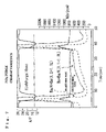
- FIG. 10 is a diagram showing experimental results in the case where the exhaust emission control apparatus according to the third embodiment is used.
- FIG. 11 is a view showing a fourth embodiment of the present invention.
- FIGS. 12A and 12B are views schematically showing the constructions of conventional exhaust emission control apparatuses, in which FIG. 12A shows a first prior art, and FIG. 12B shows a second prior art.
- FIG. 1 illustrates an exhaust emission control apparatus according to a first embodiment of the present invention, which is provided with an exhaust emission purifying catalyst 26 disposed in an exhaust system, and an internal combustion engine equipped with the exhaust emission control apparatus.
- the internal combustion engine is implemented by a four-cycle multiple cylinder gasoline engine (hereinafter referred to only as “the engine 1 ”).
- the engine 1 is constructed such that a combustion chamber 6 is enclosed by a cylinder 3 in a cylinder block 2 , a piston 4 which slides upward and downward in the cylinder 3 , and a cylinder head 5 which integrally overlaps the upper surface of the cylinder block 2 .
- the combustion chamber 6 is provided for each cylinder (only one cylinder is illustrated in FIG. 1 ).
- An electromagnetic fuel injection valve 7 is attached to the combustion chamber 6 .
- the fuel injection valve 7 is capable of performing fuel injection in an intake stroke injection mode in which fuel is injected into the combustion chambers 6 in intake strokes, a compression stroke injection mode in which fuel is injected in compression strokes, and an expansion stroke injection mode in which fuel is injected in expansion strokes.
- the engine 1 is capable of operating at a stoichiometric air-fuel ratio, a rich-air fuel ratio (rich air-fuel ratio operation), and a lean air fuel ratio (lean air-fuel ratio operation). Particularly in the compression stroke injection mode, the engine 1 is capable of operating at an ultra-lean air-fuel ratio which is higher than in lean air-fuel ratio operation in intake strokes.
- the fuel injection valve 7 , an intake valve 8 , an exhaust valve 9 , and an ignition plug 11 are arranged at such respective locations of each combustion chamber 6 as not to interfere with each other.
- a cavity 12 which is concaved in a semispherical form is formed at the top of the piston 7 within the cylinder 3 .
- the cavity 12 cooperates with an intake port 13 to generate a reverse tumble flow S in a clockwise direction as viewed in FIG. 1 .
- An intake port is formed in a substantially upright direction for the cylinder head 5 of each cylinder, and an intake manifold 14 , a surge tank 15 , an intake pipe 17 having a throttle valve 16 , an air cleaner 18 , and an air-side opening 19 , all of which constitute an intake system Ri, are connected in this order to each intake port (only one intake port is illustrated in FIG. 1 ) 13 so that the air can be taken along the intake system Ri.
- the throttle valve 16 is a drive-by-wire (DBW) type electric-operated valve provided with a throttle position sensor 21 which detects the throttle valve opening ⁇ th. It should be noted that an air flow sensor 20 which detects the intake air quantity Qa is provided in the vicinity of the air cleaner 18 in the intake system Ri.
- the engine 1 is provided with a crank angle sensor 22 which detects the crank angle; the crank angle sensor 22 is capable of detecting the engine speed Ne.
- the cylinder head 5 of each cylinder is formed with an exhaust port 23 in a substantially horizontal direction.
- An exhaust manifold 24 forming an exhaust system Re, an exhaust pipe (exhaust passage) 25 , the exhaust emission purifying catalyst device 26 constituting the essential part of the exhaust emission control apparatus, a downstream exhaust pipe 27 , and a muffler, not shown, all of which constitute an exhaust system Re, are connected in this order to each exhaust port (only one exhaust port is illustrated in FIG. 1 ) 23 so that exhaust gas can be externally emitted along the exhaust system Re.
- a temperature sensor 28 which detects the exhaust temperature is provided just upstream of the exhaust emission purifying catalyst device 26
- an air-fuel ratio sensor 30 which detects the air-fuel ratio is provided upstream of the temperature sensor 28 .
- the exhaust emission purifying catalyst device 26 is comprised of a cylinder-shaped casing 29 whose inner diameter is enlarged so as to be continuous to the exhaust pipe 25 and the downstream exhaust pipe 27 , a single carrier 32 disposed in the casing 29 having a large number of through holes 31 (refer to FIG. 3 ) passed through the carrier 32 in an axial direction, supporting layers 33 (refer to FIG. 3 ) formed of fire-resistant inorganic oxide formed on inner surfaces which define the respective through holes 31 , and catalyst components 34 (refer to FIG. 3 ) formed of noble metal and supported on the supporting layers 33 .
- the single carrier 32 is composed mainly of alumina and is formed to have a honeycomb structure including the supporting layers 33 formed on the inner surfaces defining the respective through holes 31 .
- the single carrier 32 is divided into two areas in its axial direction, i.e. in the flowing direction f in the exhaust system Re, and the components of the single carrier 32 are separately set in an exhaust passage upstream area a and an exhaust passage downstream area b as described below. Also, the quantities of noble metal supported on the internal supporting layers 33 on the inner surfaces of the respective through holes 31 are separately set in the exhaust passage upstream area a and the exhaust passage downstream area b as below.
- the single carrier 32 appearing in FIGS. 1 and 2A is constructed such that alkali metal composed mainly of potassium (K) which exhibits a high NO x trapping capability at a relatively high temperature is adopted as a NO x trapping agent for the supporting layers 33 in the exhaust passage upstream area a, and alkali earth metal mainly composed mainly of barium (Ba) considered to give a relatively small adverse effect on the three-way catalyst performance of noble metal is adopted as a NO x trapping agent for the supporting layers 33 in the exhaust passage downstream area b.
- K potassium
- Ba barium
- PT platinum
- the rich purge time Tr is set to be equal to or smaller than a predetermined value so that the amount of the noble metal 34 supported in the exhaust passage upstream area a can be smaller than the amount of the noble metal 34 supported in the exhaust passage downstream area b for the reason described below.
- the amount of the noble metal 34 supported in the exhaust passage upstream area a is set to 3.0 g/L
- the amount of the noble metal 34 supported in the exhaust passage downstream area b is set to 5.0 g/L
- the rich purge time Tr is set to 3.0 seconds.
- the inventors of the present invention conducted performance tests on the exhaust emission purifying catalyst 26 using an engine constructed as shown in FIG. 1 and obtained results shown in FIGS. 7 and 8 .
- the NO x purifying efficiency in the case where the supported amount of the noble metal 34 was set to 5.0 g/L in the exhaust passage downstream area b and set to 3.0 g/L in the exhaust passage upstream area a, and in the case where the supported amount of the noble metal 34 was set to 3.0 g/L in the exhaust passage downstream area b and set to 5.0 g/L in the exhaust passage upstream area a was found.
- the rich purge time Tr was equal to or shorter than 3.5 seconds, the NO x purifying efficiency could be kept at a higher level in the case where the supported amount of the noble metal 34 in the exhaust passage upstream area a was as small as 3.0 g/L.
- the outlet NO x concentration (ppm) relative to the inlet NO x concentration (ppm) in the case where the rich purge time Tr (refer to FIG. 5 ) was set to 4.0 seconds was found.
- the amount of the noble metal 34 supported in the exhaust passage upstream area a is set to be smaller than in the exhaust passage downstream area b, and the supporting layers 33 in the exhaust passage upstream area a are composed mainly of alkali metal such as potassium.
- platinum is used as the noble metal 34 supported on the supporting layers 33
- at least one selected from metals of the platinum family such as palladium and rhodium may be used instead of platinum (Pt).
- platinum (Pt) is used.
- potassium is disposed on the upstream supporting layers, the NO x occluding performance can be achieved up to a higher temperature as compared with barium.
- the carrier 32 of the exhaust emission purifying catalyst device 26 appearing in FIGS. 1 and 2A is constructed such that the supporting layers 33 in the exhaust passage upstream area a are formed of alkali metal composed mainly of potassium (K), and a relatively small amount of platinum (Pt) is supported on the supporting layers 33 , so that the supporting layers 33 in the exhaust passage upstream area a can serve as a NO x catalyst section E 1 which mainly exhibits an improved NO x trapping capability.
- the supporting layers 33 in the exhaust passage downstream area b are formed of alkali metal mainly composed of barium (Ba) considered to give a small adverse effect on the three-way catalyst performance of noble metal, and a relatively large amount of platinum (Pt) is supported on the supporting layers 33 , so that the supporting layers 33 in the exhaust passage upstream area a can serve as a three-way catalyst section E 2 which mainly fulfills a three-way function.
- alkali metal mainly composed of barium (Ba) considered to give a small adverse effect on the three-way catalyst performance of noble metal, and a relatively large amount of platinum (Pt) is supported on the supporting layers 33 , so that the supporting layers 33 in the exhaust passage upstream area a can serve as a three-way catalyst section E 2 which mainly fulfills a three-way function.
- the NO x catalyst section E 1 upstream in the exhaust emission purifying catalyst device 26 has a NO x emitting and reducing function of temporarily occluding NO x in an oxygen-excess atmosphere in which the air-fuel ratio of exhaust gas is lean, and emitting the occluded NO x when the air-fuel ratio of exhaust gas is stoichiometric or rich, i.e., in a reducing atmosphere in which HC and CO exist, so that the occluded NO x can be reduced to nitrogen (N2) and carbon dioxide (CO2).
- N2 nitrogen
- CO2 carbon dioxide
- the downstream three-way catalyst section E 2 has a three-way catalyst function of purifying CO, HC, and NO x in exhaust gas in an atmosphere in which the air-fuel ratio of exhaust gas is stoichiometric or rich. It should be noted that the three-way catalyst section E 2 also has a function of reducing NO x which has been emitted from the NO x catalyst section E 1 but has not been sufficiently reduced by the NO x catalyst section E 1 . Further, since barium which is considered to give a relatively small adverse effect on the three-way catalyst performance of noble metal is supported on the downstream side of the carrier 32 , the three-way function can be fulfilled in an efficient manner.
- a vehicle is equipped with a controller (hereinafter referred to only as “the ECU 35 ”) as an engine control means.
- the ECU 35 is provided with an input/output device, a storage device which stores control programs, control maps, and so forth, a central processing unit, a timer, and a counter, and so forth.
- the ECU 35 controls the exhaust emission purifying catalyst device 26 as well as the engine 1 .
- the information detected by various sensors is input to the ECU 35 .
- the ECU 35 determines the fuel injection mode, the fuel injection quantity, the ignition timing, and so forth, and provides control to drive the fuel injection valves 7 and the ignition plugs 11 .
- the engine 1 injects fuel in or after the medium stage of a compression stroke and collects a small amount of fuel only in the vicinity of the ignition plugs 11 so that the air-fuel ratio of exhaust gas can be stoichiometric or rich only in the vicinity of the ignition plugs 11 .
- fuel is injected from the fuel injection valves 7 in intake strokes and uniformly distributed to the entire combustion chambers 6 so that pre-mixture combustion can be performed with the exhaust air-fuel ratio in the combustion chambers 6 being stoichiometric (about 15) or lean.
- the target cylinder inner pressure corresponding to engine load i.e., the target mean effective pressure Pe is found from the throttle valve opening ⁇ th detected by the throttle position sensor 21 (or the operated amount of an accel pedal sensor, not shown) and the engine speed Ne detected by the crank angle sensor 22 . Also, in the fuel supply control, a fuel injection mode is set according to the target mean effective pressure Pe and the engine speed Ne with reference to a map, not shown.
- the fuel injection mode is set to the compression stroke injection mode in which fuel is injected in compression strokes (as indicated by PL in FIG. 5 ).
- the fuel injection mode is set to the intake stroke injection mode in which fuel is injected in intake strokes (as indicated by PH in FIG. 5 ).
- the target air-fuel ratio as a control objective in each fuel injection mode is set according to the target mean effective pressure Pe and the engine speed Ne, and a proper fuel injection volume is determined according to the target air-fuel ratio.
- the NO x catalyst section E 1 of the exhaust emission purifying catalyst device 26 purifies exhaust emission by occluding NO x in exhaust gas as nitrate when the air-fuel ratio of exhaust gas is lean.
- the air-fuel ratio of exhaust gas is stoichiometric or rich
- the nitrate occluded to the NO x catalyst section E 1 and CO in exhaust gas react with each other to generate carbonate and emit NO x . Therefore, when the amount of NO x occluded to the NO x catalyst section E 1 increases, such control is provided as to make the air-fuel ratio rich (rich purge).
- the concentration of oxygen in exhaust gas is lowered, HC and CO are supplied to the NO x catalyst section E 1 , and NO x is emitted from the NO x catalyst section E 1 and reduced to maintain the NO x occluding function.
- the ECU 35 does not only provides the above described fuel supply control, but also functions as a NO x emitting means A 1 for lowering the concentration of oxygen in exhaust gas to emit NO x from the NO x catalyst section E 1 .
- the NO x emitting means A 1 has a rich purging function of making the exhaust air-fuel ratio rich in the rich purge time Tr (e.g., 2 seconds), and then making the exhaust air-fuel ratio rich again in the lean duration Lt (refer to FIG. 4 ; e.g., 30 seconds) in accordance with a rich purge instruction for emitting NO x from the NO x catalyst section E 1 .
- Tr rich purge time
- Lt lean duration
- the NO x catalyst section E 1 of the exhaust emission purifying catalyst device 26 oxidizes NO x in exhaust gas to generate nitrate, so that NO x is occluded to purify exhaust emission.
- the air-fuel ratio of exhaust gas is a stoichiometric or rich air-fuel ratio e 2 (an atmosphere in which the oxygen concentration has been reduced; refer to FIGS. 4 and 5 )
- the NO x catalyst section E 1 causes the occluded nitrate and HC and CO in exhaust gas to react with each other to generate carbonate, so that NO x is emitted.
- a regenerating instruction is sent to the NO x emitting means A 1 , so that the NO x emitting means A 1 controls the air-fuel ratio to a stoichiometric or rich air-fuel ratio to lower the oxygen concentration and emits NO x from the NO x catalyst section E 1 to carry out a NO x purging process (regenerating process).
- the ECU 35 drives the fuel injection valves 7 via a fuel injection driving circuit 37 .
- the fuel injection driving circuit 37 drives the fuel injection valves 7 in, e.g., lean pulse injection PL, stoichiometric and rich pulse injection PH, and purge pulse injection PP (refer to FIG. 5 ). Due to such differences in injection patterns, exhaust gas processing characteristics in the exhaust emission purifying catalyst device 26 varies after combustion. When the lean pulse injection PL is performed, NO x in exhaust gas is occluded by the NO x catalyst section E 1 .
- the NO x catalyst section E 1 causes the supporting layers 33 to occlude NO x so as to purify NO x .
- the rich pulse injection PH when the air-fuel ratio of exhaust gas reaches an approximately stoichiometric air-fuel ratio, the amount of reducing agents such as HC and CO starts increasing in exhaust gas, but at this time point, the NO x catalyst section E 1 in front of the three-way catalyst section E 2 cannot sufficiently reduce NO x emitted from the NO x catalyst section E 1 since the amount of reducing agents (such as the remaining CO and HC) is not enough to reduce NO x emitted from the NO x catalyst section E 1 and hence the amount of emitted NO x is larger than the amount of NO x to be reduced.
- the amount of reducing agents such as the remaining CO and HC
- the NO x emitting means 32 gives an instruction for performing the rich pulse injection PH in which the target air-fuel ratio is a rich air-fuel ratio, and at least when the air-fuel ratio of exhaust gas is switched to an approximately stoichiometric air-fuel ratio, the NO x emitting means 32 gives an instruction for performing the purge pulse injection PP in expansion strokes to supply reducing agents to make up for a deficiency of reducing agents in NO x reduction.
- the fuel injection driving circuit 37 sets a counter therein so as to drive the fuel injection valves 7 in the purge pulse injection PP (refer to FIG. 5 ) as well as the rich pulse injection PH.
- the three-way catalyst section E 2 on which a relatively large amount of noble metal 34 is supported and which does not inhibit the three-way catalyst performance can purify CO and HC as well as NO x which is emitted from the NO x catalyst section E 1 and cannot be sufficiently reduced. Therefore, it is possible to suppress the emission of NO x , CO and HC into the air, and NO x emitted form the NO x catalyst section E 1 can be prevented from being directly emitted into the air.
- reducing the supported amount of the noble metal 34 can minimize the effect of the consumption of reducing agents by the noble metal 34 during rich purge, and makes it possible to satisfactorily emit NO x from the NO x catalyst section E 1 and reduce NO x . Therefore, the NO x absorbing function of the NO x trapping agents can be fulfilled during lean air-fuel ratio operation.
- the NO x purge control is provided in the middle of the fuel supply control in a main routine, not shown, executed by the ECU 35 .
- the fuel injection driving circuit 37 counts the fuel injection timing and the fuel injection time using a counter, not shown, in accordance with an injection pattern designated by the ECU 35 , and causes the fuel injection valves 7 to inject fuel. For example, if the target air-fuel ratio is set to a lean air-fuel ratio (as indicated by Se 1 in FIGS. 4 and 5 ), an instruction for performing lean air-fuel ratio operation is given, and the fuel injection driving circuit 37 drives the fuel injection valves 7 in the lean pulse injection PL in FIGS. 4 and 5 . Further, if the target air-fuel ratio is switched from the lean air-fuel ratio to a stoichiometric or rich air-fuel ratio, the fuel injection driving circuit 37 drives the fuel injection valves 7 in the rich pulse injection PH in FIG. 5 .
- step S 2 it is determined whether or not the temperature T of the NO x catalyst section E 1 and the three-way catalyst section E 2 has become equal to or higher than an activation temperature Ts (this is estimated according to the exhaust temperature detected by the temperature sensor 28 ), and if it is determined that the temperature T of the NO x catalyst section E 1 and the three-way catalyst section E 2 is equal to or higher than the activation temperature T 2 , it is then determined in step S 3 whether or not the duration t 1 of a lean mode is equal to or higher than the lean duration Lt.
- an activation temperature Ts this is estimated according to the exhaust temperature detected by the temperature sensor 28
- the lean duration Lt is determined such that the following requirements (1) to (3) are satisfied:
- the lean duration Lt is equal to or shorter than a period of time which is elapsed until it becomes impossible to occlude NO x to the NO x catalyst section E 1 during lean air-fuel ratio operation and the emission of NO x into the air starts;
- the lean duration Lt is equal to or smaller than a predetermined value since the catalyst temperature lowers if the lean air-fuel ratio operation continues for a long period of time;
- the lean duration Lt is equal to or smaller than a predetermined value so as to prevent the NO x purge unnecessary time tu (refer to FIG. 5 ), which is required for the air-fuel ratio to switch from a lean air-fuel ratio to a stoichiometric air-fuel ratio at the start of NO x purge, from increasing to deteriorate fuel economy.
- step S 3 If the determination result is positive (YES) in step S 3 , this means that conditions for starting providing control to emit the occluded NO x from the NO x reducing catalyst E 1 and reducing the same are satisfied, the process proceeds to step S 4 wherein the rich purge time Tr for which the purge pulse injection PP is performed and the pulse injection time Ti for which the purge pulse injection PP is performed are set in step S 4 .
- the rich purge time Tr is set according to the product of a map value based on the exhaust flow rate such as the intake air volume Qa detected by the air flow sensor 20 and a map value based on the degree of deterioration of the NO x catalyst section E 1 such as the travel distance Km (detected by an accumulated distance detecting device 36 ).
- the rich purge time Tr is set to about 1 to 5 seconds, for example, and is set to become shorter with a decrease in an area n where the NO x emission speed is high as shown in the diagram of FIG. 5 showing the NO x emission characteristics becomes smaller as the travel distance increases. This suppresses the deterioration of fuel economy and the emission of unburned HC and CO.
- the pulse injection time Ti is set to about 0.1 to 1 second, for example, and is set to be decreased to about 1 ⁇ 2 as the travel distance i.e. the degree of deterioration increases.
- the reason why the pulse injection time Ti is decreased is that if the degree of deterioration of the NO x catalyst 15 increases, the NO x emission characteristics vary such that the area n where the NO x emission speed is high (refer to FIG. 5 ) becomes smaller, and hence only a small amount of reducing agents suffices. Since the pulse injection time Ti is set to be short, the deterioration of fuel economy and the emission of unburned HC can be suppressed.
- step S 5 After the rich purge time Tr and the pulse injection time Ti are set and counting is started in step S 4 , it is determined in step S 5 whether the rich purge time Tr has elapsed or not. If the rich purge time Tr has not elapsed, the process proceeds to step S 6 wherein an instruction for performing the purge pulse injection PP for the pulse injection time Ti is given.
- the fuel injection driving circuit 37 drives the fuel injection valves 7 in such a pattern that the purge pulse injection PP is performed immediately after the rich pulse injection (refer to the pulse injection volume in FIG. 5 ). It should be noted that the purge pulse injection PP is performed at least when the air-fuel ratio of exhaust gas is switched from a lean air-fuel ratio to an approximately stoichiometric air-fuel ratio so that the emitted NO x can be effectively reduced.
- the purge pulse injection PP after the rich pulse injection PH is performed in the medium stage of an expansion stroke to the initial stage of an expansion stroke, and more particularly in the later stage of an expansion stroke.
- the addition of fuel in the later stage of an expansion stroke supplies unburned fuel (reducing agent) which has not been combusted into exhaust passages (refer to the NO x concentration in FIG. 4 ), and in particular, when the air-fuel ratio of exhaust gas is switched to a stoichiometric air-fuel ratio, a rapidly increasing amount of NO x absorbed to the NO x catalyst section E 1 is emitted (refer to the NO x concentration in FIGS. 4 and 5 ), but the emitted NO x can be effectively reduced.
- step S 6 After the pulse injection is performed in step S 6 , the purge flag PFLG is set to “1” in step S 7 to terminate the present control, and the process returns to the main routine. It is determined again whether the purge flag PFLG is set to 1 or not. If the determination result is positive, the process proceeds to step S 5 . If the rich purge time Tr has not elapsed yet, steps S 5 , S 6 , and S 7 are executed again to sequentially perform the rich pulse injection PH and the purge pulse injection PP, so that NO x is emitted from the NO x catalyst section E 1 and reduced.
- the purge flag PFLG is set again to “0” in step S 8 , and the rich pulse injection PH and the purge pulse injection PP are terminated in step S 9 .
- the process then returns to the main routine.
- fuel injection is performed by providing fuel injection control in the main routine of the ECU 35 .
- the supported amount of noble metal 34 is set to 3.0 g/L in the exhaust passage upstream area a and is set to 5.0 g/l in the exhaust passage downstream area b, so that the consumption of HC and CO (reducing agents) by platinum Pt (noble metal) in the exhaust passage upstream area a is suppressed, so that the remaining reducing agents can positively reduce NO x emitted from the NO x catalyst section E 1 to improve the NO x purifying efficiency.
- the outlet side NO x indicated by a chain line in FIG. 4 can be smaller than the inlet side NO x indicated by a solid line in FIG. 4 , and the rich purge time can be relatively short. Therefore, the fuel injection volume is reduced.
- the amount of noble metal is set to be smaller in the exhaust passage upstream area than in the exhaust passage downstream area, and alkali metal composed mainly of potassium (K) which maintains the NO x occluding capability up to a relatively high temperature is supported in the exhaust passage upstream area of the carrier, so that the exhaust passage upstream area of the carrier functions as the NO x catalyst section which exhibits an improved NO x trapping catalyst function.
- K potassium
- alkali earth metal composed mainly of barium (Ba) considered to give a relatively small adverse effect on the three-way catalyst performance of noble metal is supported in the exhaust passage downstream area of the carrier, and the amount of noble metal is set to be larger in the exhaust passage downstream area than in the exhaust passage upstream area, so that the exhaust passage downstream area of the carrier functions as the three-way catalyst section.
- the NO x catalyst section E 1 on the upstream side occludes NO x during lean air-fuel ratio operation and emits and reduces the occluded NO x during rich air-fuel ratio operation (or during NO x purge). Further, during lean air-fuel ratio operation, in the exhaust passage upstream area, the consumption of supplied reducing agents is suppressed due to the presence of potassium considered relatively likely to give an adverse effect on the activity of noble metal, and thus the remaining reducing agents can positively reduce the emitted NO x .
- the three-way catalyst section E 2 on the downstream side functions as a NO x occluding catalyst due to the presence of barium during lean air-fuel ratio operation, and the consumption of reducing agents is suppressed on the upstream side during NO x purge in rich air-fuel ratio operation, so that a larger amount of reducing agents can be supplied within a short period of time to immediately make the exhaust atmosphere rich, so that NO x which is emitted from the NO x catalyst section E 1 and has not been satisfactorily reduced can be efficiently purified.
- the exhaust emission purifying catalyst device 26 shown in FIGS. 1 and 2A which is constructed such that the supporting layers 33 of the single carrier 32 are formed of alkali metal composed mainly of potassium (K) in the exhaust passage upstream area a and are formed of alkali earth metal composed mainly of barium (Ba) in the exhaust passage downstream area b, an exhaust emission purifying catalyst device 26 ′ in FIG. 2B may be used instead.
- the exhaust emission purifying catalyst device 26 ′ is provided with a carrier 32 configured as a single body, and barium (Ba) with a high HC purifying capability is supported on supporting layers 33 in both an exhaust passage upstream area a and an exhaust passage downstream area b of the carrier 32 , and as is the case with the exhaust emission purifying catalyst device 26 in FIG. 2A , the supported amount of noble metal 34 is set to 3.0 g/L in the exhaust passage upstream area a and is set to 5.0 g/L in the exhaust passage downstream area b.
- barium (Ba) with a high HC purifying capability is supported on supporting layers 33 in both an exhaust passage upstream area a and an exhaust passage downstream area b of the carrier 32 , and as is the case with the exhaust emission purifying catalyst device 26 in FIG. 2A , the supported amount of noble metal 34 is set to 3.0 g/L in the exhaust passage upstream area a and is set to 5.0 g/L in the exhaust passage downstream area b.
- the exhaust emission purifying catalyst device 26 ′ in FIG. 2B obtains substantially the same operational effects as the exhaust emission purifying catalyst device 26 in FIG. 2A . Specifically, when the air-fuel ratio is switched to a rich air-fuel ratio, the consumption of HC and CO (reducing agents) by noble metal in the exhaust passage upstream area a is suppressed, so that the remaining reducing agents can positively reduce NO x emitted from the NO x catalyst section E 1 to thus improve the NO x purifying efficiency.
- HC and CO reducing agents
- the amount of the noble metal 34 supported on the supporting layers 33 in the exhaust passage upstream area a of the carrier 32 is set to 3.0 g/L, and the amount of the noble metal 34 supported on the supporting layers 33 in the exhaust passage downstream area b of the carrier 32 is set to 5.0 g/L; i.e., the amount of the noble metal 34 is separately set in the exhaust passage upstream area a and the exhaust passage downstream area b
- the present invention is not limited to this, but the supported amount of the noble metal 34 may be set to be gradually increased from the exhaust passage upstream end to the exhaust passage downstream end (gradation).
- the present invention is not limited to this, but potassium K and barium B may be supported in the whole area of the carrier 32 such that a higher percentage of potassium (K) (up to 100%) is supported at the exhaust passage upstream end and a higher percentage of barium (Ba) is supported at the exhaust passage downstream end, and the percentage of potassium (K) is gradually reduced and the percentage of potassium (K) is gradually raised from the exhaust passage upstream end to the exhaust passage downstream end (gradation).
- potassium (K) may be supported in the whole area of the carrier 32 such that a higher percentage of potassium (K) is supported at the exhaust passage upstream end, and the percentage of potassium (K) is gradually reduced from the exhaust passage upstream end to the exhaust passage downstream end (gradation).
- the purge pulse injection PP is performed in expansion strokes
- the present invention is not limited to this, but the same effects as in the above described embodiments can be obtained if the air-fuel ratio is changed as below.
- NO x purge if the air-fuel ratio in the rich pulse injection PH is controlled to such a value as to satisfactorily emit and reduce NO x , and when the air-fuel ratio of exhaust gas is switched from a lean air-fuel ratio to an approximately stoichiometric air-fuel ratio, the degree of richness is increased so that the air-fuel ratio can be considerably higher than a stoichiometric air-fuel ratio, the same effects as in the above described embodiments can be obtained.
- a spark ignition type internal combustion engine which directly injects fuel into combustion chambers is used as an internal combustion engine to which the exhaust emission control apparatus is applied
- the present invention may be applied to a diesel engine, or a spark ignition type lean burn engine which injects fuel into intake pipes and leads an air-fuel mixture into combustion chambers.
- the purge pulse injection PP is performed in expansion strokes
- the present invention is not limited to this, but in an engine of the type that fuel is injected into intake pipes (intake passages), the same effects as in the above described embodiments can be obtained if the air-fuel ratio is changed as below.
- the third embodiment in FIGS. 9 differs from the above described first embodiment in that an exhaust emission purifying catalyst device (NO x occluding catalyst unit) 130 shown in FIG. 9 is used in place of the exhaust emission purifying catalyst device 26 shown in FIG. 1 , and description of the same component parts is omitted.
- the exhaust emission purifying catalyst device 130 is constructed such that a carrier 132 is divided into an exhaust passage upstream area 132 a and an exhaust passage downstream area 132 b , and the supported amount of O2 storage agent 134 is set to be smaller in the exhaust passage upstream area 132 a than in the exhaust passage upstream area 132 b.
- the NO x occluding catalyst unit 130 is comprised of the carrier 132 configured as a single body having a large number of through holes passed through the carrier 132 , and supporting carriers made of fire-resistance inorganic oxide formed on inner surfaces which define the through holes.
- Any noble metal 136 selected from copper (Cu), cobalt (Co), silver (Ag), platinum (Pt), palladium (Pd), and rhodium (Rh) is supported as active noble metal on the supporting layers, and alkali metal (such as potassium (K) and sodium (Na)) and alkali earth metal (such as barium (Ba)) are supported as NO x occluding agents.
- the NO x occluding catalyst unit 130 basically has a NO x occluding catalyst function of occluding NO x when the air-fuel ratio of exhaust gas is lean and in an oxygen-excess atmosphere in which the oxygen concentration is high, and emitting the occluded NO x when the air-fuel ratio of exhaust gas is rich and in an oxygen concentration reduced atmosphere in which the oxygen concentration is low, to thus reduce and remove the NO x by catalytic action of the noble metal 136 .
- the NO x occluding catalyst unit 130 also has a function of a three-way catalyst function since the above-mentioned noble metal 136 is supported on the supporting layers.
- the NO x occluding catalyst unit 130 can satisfactorily purify HC and CO as well as NO x when the air-fuel ratio of exhaust is stoichiometric or rich.
- the NO x occluding catalyst unit 130 also has an O2 storage function (oxygen occluding function; also called “OSC”); an O2 storage agent (oxygen occluding agent; OSC agent) such as cerium (Ce) is supported on the supporting layers.
- O2 storage function oxygen occluding function; also called “OSC”
- OSC agent oxygen occluding agent
- Ce cerium
- the NO x occluding catalyst unit 130 has a function of occluding O2 (oxygen) when the air-fuel ratio of exhaust gas is lean and in an oxygen-excess atmosphere, and emitting the occluded O2 when the air-fuel ratio of exhaust gas is rich and in an oxygen concentration reduced atmosphere.
- the target air-fuel ratio of exhaust gas is stoichiometric or rich and, for example, the above-mentioned O2 sensor 30 provides O2 feedback control
- the change is adjusted by O2 occluded by the O2 storage agent 134 , and thus the NO x occluding catalyst unit 130 can maintain the catalyst atmosphere at an approximately stoichiometric air-fuel ratio. It is therefore possible to fulfill the three-way catalyst function.
- the supported amount of the O2 storage agent (indicated by dots) 134 is set to be smaller in the exhaust passage upstream area 132 a than in the exhaust passage downstream area 132 b in the carrier 132 .
- the amount of the O2 storage agent 134 is set to be smaller in the exhaust passage upstream area 132 a than in the exhaust passage downstream area 132 b.
- the O2 storage agent 134 is capable of occluding O2 due to the presence of the noble metal 136 , and here, as schematically shown in FIG. 9 , the supported amount of the noble metal (indicated by small circles) 136 is set to be smaller in the exhaust passage upstream area 132 a than in the exhaust passage downstream area 132 b in the carrier 132 according to the supported amount of the O2 storage agent 134 .
- the fuel injection mode is switched to a NO x purge mode, and the air-fuel ratio of exhaust gas is made rich, and the catalyst atmosphere is changed to the above-mentioned atmosphere in which the oxygen concentration is low.
- reducing agents such as CO and HC are discharged into exhaust passages to start NO x purge.
- the O2 storage agent 134 is supported on the NO x occluding catalyst unit 130 , such that the supported amount of the O2 storage agent 134 is set to be smaller in the exhaust passage upstream area 132 a than in the exhaust passage downstream area 132 b in the carrier 132 .
- the amount of the O2 storage agent 134 is smaller in the exhaust passage upstream area 132 a than in the exhaust passage downstream area 132 b , reducing agents such as CO and HC can be prevented from being entirely consumed in the exhaust passage upstream area 132 a due to oxidative reaction with O2 occluded to the O2 storage agent 134 , even if NO x purge is carried out.
- the NO x occluded to the exhaust passage upstream area 132 a can be emitted and reduced, and reducing agents such as CO and HC can surely reach the exhaust passage downstream area 132 b .
- the NO x occluded to the exhaust passage downstream area 132 b can be satisfactorily emitted and reduced without the necessity of increasing fuel so as to increase reducing agents such as CO and HC.
- the O2 covers the noble metal 136 to degrade the activity thereof (oxygen poisoning), but if reducing agents such as CO and HC can surely reach the exhaust passage downstream area 132 b during NO x purge, the O2 which covers the noble metal 136 can be surely reduced by the reducing agents not only in the exhaust passage upstream area 132 a but also in the exhaust passage downstream area 132 b . This makes it possible to satisfactorily restore the activity of the noble metal 136 .
- the exhaust emission purifying catalyst device is capable of efficiently restoring the NO x occluding capability of the NO x occluding catalyst unit 130 as a whole and the activity of the noble metal 136 in a short period of NO x purge time and without deteriorating fuel economy, and thus improving the exhaust emission purifying efficiency.
- FIG. 10 shows an experimental result after NO x purge as the outlet NO x concentration of the NO x occluding catalyst unit 130 in the case where the exhaust emission purifying catalyst device according to the present embodiment, and according to this experimental result, if the supported amount of the O2 storage agent 134 is set to be smaller in the exhaust passage upstream area 132 a than in the exhaust passage downstream area 132 b in the carrier 132 (as indicated by a solid line), it is possible to satisfactorily restore the NO x occluding capability and improve the NO x purifying efficiency and the exhaust emission purifying efficiency as compared with the prior art in which a uniform amount of O2 storage agent 134 is supported (as indicated by a broken line). It should be noted that FIG. 10 also shows the air-fuel ratio during NO x purge and the inlet NO x concentration of the NO x occluding catalyst unit 130 (a chain line).
- the supported amount of the noble metal 136 is set to be smaller in the exhaust passage upstream area 132 a than in the exhaust passage downstream area 132 b in the carrier 132 according to the supported amount of the O2 storage agent 134 , neither too much nor too little noble metal 136 which is relatively expensive can be effectively supported on the NO x occluding catalyst unit 130 .
- the supported amount of the noble metal 136 should not necessarily be changed, but a uniform amount of the noble metal 136 may be supported on the carrier 132 .
- the carrier 132 is divided into the exhaust passage upstream area 132 a and the exhaust passage downstream area 132 b , in which different amounts of the O2 storage agent 134 are supported, but in the fourth embodiment, as shown in FIG. 11 , a NO x occluding catalyst unit 130 ′ is used which is configured such that the supported amount of the O2 storage agent 134 is gradually increased (gradation) from the exhaust passage upstream area 132 a to the exhaust passage downstream area 132 b.
- the supported amount of the noble metal 136 may be gradually increased (gradation) from the exhaust passage upstream area 132 a to the exhaust passage downstream area 132 b.
Landscapes
- Engineering & Computer Science (AREA)
- Chemical & Material Sciences (AREA)
- Chemical Kinetics & Catalysis (AREA)
- Combustion & Propulsion (AREA)
- Mechanical Engineering (AREA)
- General Engineering & Computer Science (AREA)
- Health & Medical Sciences (AREA)
- Oil, Petroleum & Natural Gas (AREA)
- Analytical Chemistry (AREA)
- General Chemical & Material Sciences (AREA)
- Environmental & Geological Engineering (AREA)
- Toxicology (AREA)
- Biomedical Technology (AREA)
- Organic Chemistry (AREA)
- Materials Engineering (AREA)
- Exhaust Gas After Treatment (AREA)
- Exhaust Gas Treatment By Means Of Catalyst (AREA)
Applications Claiming Priority (6)
| Application Number | Priority Date | Filing Date | Title |
|---|---|---|---|
| JP2003203580 | 2003-07-30 | ||
| JP2003-203580 | 2003-07-30 | ||
| JP2004-21477 | 2004-01-29 | ||
| JP2004021477A JP4359765B2 (ja) | 2004-01-29 | 2004-01-29 | 排気浄化触媒装置 |
| JP2004-202934 | 2004-07-09 | ||
| JP2004202934A JP2005058997A (ja) | 2003-07-30 | 2004-07-09 | 排気浄化触媒装置 |
Publications (2)
| Publication Number | Publication Date |
|---|---|
| US20050084427A1 US20050084427A1 (en) | 2005-04-21 |
| US7344684B2 true US7344684B2 (en) | 2008-03-18 |
Family
ID=34222148
Family Applications (1)
| Application Number | Title | Priority Date | Filing Date |
|---|---|---|---|
| US10/901,097 Expired - Fee Related US7344684B2 (en) | 2003-07-30 | 2004-07-29 | Exhaust emission purifying catalyst device |
Country Status (3)
| Country | Link |
|---|---|
| US (1) | US7344684B2 (de) |
| KR (1) | KR100570590B1 (de) |
| DE (1) | DE102004036478B4 (de) |
Cited By (2)
| Publication number | Priority date | Publication date | Assignee | Title |
|---|---|---|---|---|
| US9744529B2 (en) | 2014-03-21 | 2017-08-29 | Basf Corporation | Integrated LNT-TWC catalyst |
| US10130913B2 (en) * | 2015-01-20 | 2018-11-20 | Isuzu Motors Limited | Exhaust gas purification system, and NOx purification capacity restoration method |
Families Citing this family (6)
| Publication number | Priority date | Publication date | Assignee | Title |
|---|---|---|---|---|
| JP4654746B2 (ja) * | 2005-04-14 | 2011-03-23 | マツダ株式会社 | 排気ガス浄化触媒装置 |
| JP2006334490A (ja) * | 2005-06-01 | 2006-12-14 | Mazda Motor Corp | 排気ガス浄化用触媒 |
| JP5373255B2 (ja) * | 2006-05-29 | 2013-12-18 | 株式会社キャタラー | NOx還元触媒、NOx還元触媒システム、及びNOx還元方法 |
| JP4485564B2 (ja) * | 2007-11-07 | 2010-06-23 | トヨタ自動車株式会社 | 内燃機関の排気浄化装置 |
| EP2650042B2 (de) * | 2012-04-13 | 2020-09-02 | Umicore AG & Co. KG | Schadstoffminderungssystem für Benzinfahrzeuge |
| DE102015204080B4 (de) * | 2015-03-06 | 2017-01-26 | Ford Global Technologies, Llc | Verfahren und Steuervorrichtung zur Regeneration einer Abgasbehandlungsanordnung für Brennkraftmaschinen mit Magergemischbetrieb |
Citations (6)
| Publication number | Priority date | Publication date | Assignee | Title |
|---|---|---|---|---|
| US4118199A (en) * | 1975-09-23 | 1978-10-03 | Deutsche Gold- Und Silber-Scheideanstalt Vormals Roessler | Monolithic carrier catalyst and arrangements of such a catalyst for the purification of exhaust gases from an internal combustion engine |
| DE19522913A1 (de) | 1994-06-24 | 1996-01-04 | Toyota Motor Co Ltd | Abgasemissionssteuervorrichtung für einen Verbrennungsmotor |
| JPH112114A (ja) | 1997-06-11 | 1999-01-06 | Nissan Motor Co Ltd | 内燃機関の排気浄化装置 |
| JP2000027677A (ja) | 1998-07-10 | 2000-01-25 | Toyota Motor Corp | 希薄燃焼内燃機関の排気浄化装置 |
| US6149877A (en) * | 1997-01-21 | 2000-11-21 | Toyota Jidosha Kabushiki Kaisha | Exhaust gas purifying catalyst |
| JP2001190960A (ja) | 2000-01-11 | 2001-07-17 | Toyota Motor Corp | 排ガス浄化用触媒 |
-
2004
- 2004-07-28 DE DE102004036478A patent/DE102004036478B4/de not_active Expired - Fee Related
- 2004-07-29 US US10/901,097 patent/US7344684B2/en not_active Expired - Fee Related
- 2004-07-29 KR KR1020040059521A patent/KR100570590B1/ko not_active IP Right Cessation
Patent Citations (6)
| Publication number | Priority date | Publication date | Assignee | Title |
|---|---|---|---|---|
| US4118199A (en) * | 1975-09-23 | 1978-10-03 | Deutsche Gold- Und Silber-Scheideanstalt Vormals Roessler | Monolithic carrier catalyst and arrangements of such a catalyst for the purification of exhaust gases from an internal combustion engine |
| DE19522913A1 (de) | 1994-06-24 | 1996-01-04 | Toyota Motor Co Ltd | Abgasemissionssteuervorrichtung für einen Verbrennungsmotor |
| US6149877A (en) * | 1997-01-21 | 2000-11-21 | Toyota Jidosha Kabushiki Kaisha | Exhaust gas purifying catalyst |
| JPH112114A (ja) | 1997-06-11 | 1999-01-06 | Nissan Motor Co Ltd | 内燃機関の排気浄化装置 |
| JP2000027677A (ja) | 1998-07-10 | 2000-01-25 | Toyota Motor Corp | 希薄燃焼内燃機関の排気浄化装置 |
| JP2001190960A (ja) | 2000-01-11 | 2001-07-17 | Toyota Motor Corp | 排ガス浄化用触媒 |
Cited By (3)
| Publication number | Priority date | Publication date | Assignee | Title |
|---|---|---|---|---|
| US9744529B2 (en) | 2014-03-21 | 2017-08-29 | Basf Corporation | Integrated LNT-TWC catalyst |
| US9981258B2 (en) | 2014-03-21 | 2018-05-29 | Basf Corporation | Integrated LNT-TWC catalyst |
| US10130913B2 (en) * | 2015-01-20 | 2018-11-20 | Isuzu Motors Limited | Exhaust gas purification system, and NOx purification capacity restoration method |
Also Published As
| Publication number | Publication date |
|---|---|
| US20050084427A1 (en) | 2005-04-21 |
| KR100570590B1 (ko) | 2006-11-23 |
| DE102004036478B4 (de) | 2007-07-19 |
| KR20050014699A (ko) | 2005-02-07 |
| DE102004036478A1 (de) | 2005-03-17 |
Similar Documents
| Publication | Publication Date | Title |
|---|---|---|
| KR100395518B1 (ko) | 내연기관의 배기 정화장치 | |
| EP1710407B1 (de) | Abgasemissions-reinigungsvorrichtung für selbstzündenden verbrennungsmotor | |
| EP1065351B1 (de) | Abgasreinigungsvorrichtung einer Brennkraftmaschine | |
| US20030066287A1 (en) | Exhaust gas purification device of internal combustion engine | |
| US6325041B1 (en) | Control apparatus for spark ignition type direct injection engine | |
| KR20010052626A (ko) | 내연 기관의 배기 정화 장치 | |
| WO2000068554A1 (fr) | Dispositif de regulation de l'emission des gaz d'echappement d'un moteur a combustion interne | |
| EP1167712B1 (de) | Vorrichtung zum Reinigen des Abgases einer Brennkraftmaschine | |
| US6594991B2 (en) | Exhaust purifying method and apparatus of an internal combustion engine | |
| US7344684B2 (en) | Exhaust emission purifying catalyst device | |
| JP3972864B2 (ja) | 内燃機関の排気浄化システム | |
| JP5994931B2 (ja) | 内燃機関の排気浄化装置 | |
| WO2014016965A1 (ja) | 内燃機関の排気浄化装置 | |
| JP3646571B2 (ja) | 内燃機関の排気浄化装置 | |
| KR100529751B1 (ko) | 내연기관의 배기정화장치 | |
| JP4345202B2 (ja) | 内燃機関の排気浄化装置 | |
| JP2005058997A (ja) | 排気浄化触媒装置 | |
| JP4019891B2 (ja) | 内燃機関の排気浄化装置 | |
| JP2005030246A (ja) | 排気ガス浄化装置 | |
| JP4359765B2 (ja) | 排気浄化触媒装置 | |
| JP4435028B2 (ja) | 内燃機関の排気浄化装置 | |
| JP2001032707A (ja) | 内燃機関の排気浄化装置及び排気ガス浄化方法及び排気ガス浄化触媒 | |
| JP2004301109A (ja) | 内燃機関の排気浄化システム | |
| JP2734907B2 (ja) | 排気ガス浄化装置 | |
| JP4983697B2 (ja) | 内燃機関の排気浄化システム |
Legal Events
| Date | Code | Title | Description |
|---|---|---|---|
| AS | Assignment |
Owner name: MITSUBISHI JIDOSHA KOGYO K.K. (A.K.A. MITSUBISHI M Free format text: ADDRESS CHANGE;ASSIGNOR:MITSUBISHI JIDOSHA KOGYO K.K. (A.K.A. MITSUBISHI MOTORS CORPORATION);REEL/FRAME:019040/0319 Effective date: 20070101 |
|
| FEPP | Fee payment procedure |
Free format text: PAYOR NUMBER ASSIGNED (ORIGINAL EVENT CODE: ASPN); ENTITY STATUS OF PATENT OWNER: LARGE ENTITY |
|
| AS | Assignment |
Owner name: MITSUBISHI JIDOSHA KOGYO KABUSHIKI KAISHA, JAPAN Free format text: ASSIGNMENT OF ASSIGNORS INTEREST;ASSIGNORS:KIKUCHI, SEIJI;IWACHIDO, KINICHI;OHHARA, HIROAKI;REEL/FRAME:020366/0876 Effective date: 20071128 |
|
| REMI | Maintenance fee reminder mailed | ||
| LAPS | Lapse for failure to pay maintenance fees | ||
| STCH | Information on status: patent discontinuation |
Free format text: PATENT EXPIRED DUE TO NONPAYMENT OF MAINTENANCE FEES UNDER 37 CFR 1.362 |
|
| FP | Lapsed due to failure to pay maintenance fee |
Effective date: 20120318 |