US7333193B2 - Analysis apparatus irradiating detection light and reading state of analysis object - Google Patents
Analysis apparatus irradiating detection light and reading state of analysis object Download PDFInfo
- Publication number
- US7333193B2 US7333193B2 US10/507,412 US50741204A US7333193B2 US 7333193 B2 US7333193 B2 US 7333193B2 US 50741204 A US50741204 A US 50741204A US 7333193 B2 US7333193 B2 US 7333193B2
- Authority
- US
- United States
- Prior art keywords
- analysis
- mark
- disc
- analysis object
- reading
- Prior art date
- Legal status (The legal status is an assumption and is not a legal conclusion. Google has not performed a legal analysis and makes no representation as to the accuracy of the status listed.)
- Expired - Lifetime, expires
Links
- 238000001514 detection method Methods 0.000 title claims description 12
- 230000001678 irradiating effect Effects 0.000 title claims description 3
- 238000012545 processing Methods 0.000 claims abstract description 24
- 230000003287 optical effect Effects 0.000 abstract description 35
- 210000004369 blood Anatomy 0.000 description 8
- 239000008280 blood Substances 0.000 description 8
- 238000012360 testing method Methods 0.000 description 8
- 238000000034 method Methods 0.000 description 6
- 238000012937 correction Methods 0.000 description 5
- 239000003550 marker Substances 0.000 description 4
- 238000010586 diagram Methods 0.000 description 3
- 230000006870 function Effects 0.000 description 3
- 230000015572 biosynthetic process Effects 0.000 description 2
- 238000009534 blood test Methods 0.000 description 2
- 239000003153 chemical reaction reagent Substances 0.000 description 2
- HVYWMOMLDIMFJA-DPAQBDIFSA-N cholesterol Chemical compound C1C=C2C[C@@H](O)CC[C@]2(C)[C@@H]2[C@@H]1[C@@H]1CC[C@H]([C@H](C)CCCC(C)C)[C@@]1(C)CC2 HVYWMOMLDIMFJA-DPAQBDIFSA-N 0.000 description 2
- 239000000203 mixture Substances 0.000 description 2
- 238000012800 visualization Methods 0.000 description 2
- 238000009825 accumulation Methods 0.000 description 1
- 235000012000 cholesterol Nutrition 0.000 description 1
- 238000012936 correction and preventive action Methods 0.000 description 1
- 230000001934 delay Effects 0.000 description 1
- 230000003111 delayed effect Effects 0.000 description 1
- 238000006073 displacement reaction Methods 0.000 description 1
- 235000020188 drinking water Nutrition 0.000 description 1
- 239000003651 drinking water Substances 0.000 description 1
- 230000000694 effects Effects 0.000 description 1
- 210000003743 erythrocyte Anatomy 0.000 description 1
- 239000000284 extract Substances 0.000 description 1
- 210000000265 leukocyte Anatomy 0.000 description 1
- 230000005236 sound signal Effects 0.000 description 1
- 239000008399 tap water Substances 0.000 description 1
- 235000020679 tap water Nutrition 0.000 description 1
- 238000013519 translation Methods 0.000 description 1
- XLYOFNOQVPJJNP-UHFFFAOYSA-N water Substances O XLYOFNOQVPJJNP-UHFFFAOYSA-N 0.000 description 1
Images


Classifications
-
- G—PHYSICS
- G11—INFORMATION STORAGE
- G11B—INFORMATION STORAGE BASED ON RELATIVE MOVEMENT BETWEEN RECORD CARRIER AND TRANSDUCER
- G11B27/00—Editing; Indexing; Addressing; Timing or synchronising; Monitoring; Measuring tape travel
- G11B27/10—Indexing; Addressing; Timing or synchronising; Measuring tape travel
- G11B27/19—Indexing; Addressing; Timing or synchronising; Measuring tape travel by using information detectable on the record carrier
- G11B27/24—Indexing; Addressing; Timing or synchronising; Measuring tape travel by using information detectable on the record carrier by sensing features on the record carrier other than the transducing track ; sensing signals or marks recorded by another method than the main recording
-
- G—PHYSICS
- G01—MEASURING; TESTING
- G01N—INVESTIGATING OR ANALYSING MATERIALS BY DETERMINING THEIR CHEMICAL OR PHYSICAL PROPERTIES
- G01N35/00—Automatic analysis not limited to methods or materials provided for in any single one of groups G01N1/00 - G01N33/00; Handling materials therefor
- G01N35/00029—Automatic analysis not limited to methods or materials provided for in any single one of groups G01N1/00 - G01N33/00; Handling materials therefor provided with flat sample substrates, e.g. slides
- G01N35/00069—Automatic analysis not limited to methods or materials provided for in any single one of groups G01N1/00 - G01N33/00; Handling materials therefor provided with flat sample substrates, e.g. slides whereby the sample substrate is of the bio-disk type, i.e. having the format of an optical disk
-
- G—PHYSICS
- G11—INFORMATION STORAGE
- G11B—INFORMATION STORAGE BASED ON RELATIVE MOVEMENT BETWEEN RECORD CARRIER AND TRANSDUCER
- G11B27/00—Editing; Indexing; Addressing; Timing or synchronising; Monitoring; Measuring tape travel
- G11B27/10—Indexing; Addressing; Timing or synchronising; Measuring tape travel
- G11B27/102—Programmed access in sequence to addressed parts of tracks of operating record carriers
- G11B27/105—Programmed access in sequence to addressed parts of tracks of operating record carriers of operating discs
-
- G—PHYSICS
- G11—INFORMATION STORAGE
- G11B—INFORMATION STORAGE BASED ON RELATIVE MOVEMENT BETWEEN RECORD CARRIER AND TRANSDUCER
- G11B2220/00—Record carriers by type
- G11B2220/20—Disc-shaped record carriers
- G11B2220/21—Disc-shaped record carriers characterised in that the disc is of read-only, rewritable, or recordable type
- G11B2220/215—Recordable discs
- G11B2220/216—Rewritable discs
-
- G—PHYSICS
- G11—INFORMATION STORAGE
- G11B—INFORMATION STORAGE BASED ON RELATIVE MOVEMENT BETWEEN RECORD CARRIER AND TRANSDUCER
- G11B2220/00—Record carriers by type
- G11B2220/20—Disc-shaped record carriers
- G11B2220/21—Disc-shaped record carriers characterised in that the disc is of read-only, rewritable, or recordable type
- G11B2220/215—Recordable discs
- G11B2220/218—Write-once discs
-
- G—PHYSICS
- G11—INFORMATION STORAGE
- G11B—INFORMATION STORAGE BASED ON RELATIVE MOVEMENT BETWEEN RECORD CARRIER AND TRANSDUCER
- G11B2220/00—Record carriers by type
- G11B2220/20—Disc-shaped record carriers
- G11B2220/25—Disc-shaped record carriers characterised in that the disc is based on a specific recording technology
- G11B2220/2537—Optical discs
- G11B2220/2562—DVDs [digital versatile discs]; Digital video discs; MMCDs; HDCDs
Definitions
- the present invention relates to an analysis apparatus in which a sample like blood, for example, is set on an optical disc for analysis and such analysis object is traced and captured as an image.
- An analysis apparatus is disclosed in Published Japanese translation of PCT international publication for patent application No. 10-504397 (WO96/09548) and so on, in which an analysis object set on the tracks of an analysis disc is traced and an image is obtained by using a compact disc for recording audio or video (hereinafter referred to as an optical disc) and the reproducing function of an optical disc drive for reproducing the disc.
- an optical disc for recording audio or video
- a typical optical disc drive is configured as shown in FIG. 9 .
- An optical disc 101 is rotationally driven in the direction of arrow C by a disc motor 102 .
- a screw shaft 105 is rotationally driven by a traverse motor 104 so that a pickup 103 for irradiating the optical disc 101 with detection light and detecting reflected light moves in the radial direction (the direction of arrow A) of the optical disc 101 .
- the traverse motor 104 and the disc motor 102 are operated by a servo control circuit 106 according to the reproduction output of the pickup 103 in the following manner:
- the servo control circuit 106 drives the traverse motor 104 so as to trace tracks composed of pits or grooves, etc., detects address information recorded on the tracks of the optical disc 101 , and drives the disc motor 102 with a constant linear velocity (CLV control).
- CLV control constant linear velocity
- the reproduction output of the pickup 103 is processed by a reproducing device 107 , so that a sound signal or a video signal that serve as data recorded on the tracks are reproduced and outputted.
- the analysis apparatus is almost identical to the typical optical disc drive in block diagram form.
- a mixture of a sample and a reagent corresponding to a test item is set on the optical disc 101 as an analysis object B in addition to a track 101 a.
- the servo control circuit 106 and the reproducing device 107 obtain an image of the analysis object B on the optical disc 101 as described below.
- the direction of an arrow on the track 101 a indicates the tracing direction of detection light from the pickup 103 .
- time information or the like composed of pits, grooves, etc. on the optical disc is formed according to the standards of conventional optical discs for recording audio or video, and thus the specific explanation thereof is omitted.
- Specific examples are Compact Disc System Description (commonly called Red Book standard) and Compact Disc Readable System Description (commonly called Orange Book standard).
- the laser irradiation point of the pickup 103 controlled by the servo control circuit 106 traces the spiral tracks 101 a of the optical disc 101 .
- the tracks 101 a have a pitch of 1.6 ⁇ m on the optical disc according to Orange Book standard.
- the pickup 103 traces 1 , 2 , 3 , . . . , 8 , . . . , in turn for each rotation of the optical disc 101 .
- the reproducing device 107 extracts only data of a portion of the analysis object B that is obtained by tracing, and reconfigures data, so that video or shape count is performed.
- the analysis apparatus may detect and process light reflected from an optical disc in the same manner as a typical optical disc drive for reproducing an optical disc, and the analysis apparatus may detect and process light passing through an optical disc.
- Absolute time is engraved as address information on a disc such as a CD and a DVD.
- the time information is composed of minutes, seconds, and frames.
- One second is constituted of 75 frames.
- the recording system of the time information is broadly divided into the following two kinds: a system for recording data by changing a length of a pit such as EFM and a system for recording after a groove is snaked by FM modulation on a recording disc.
- An analysis apparatus for a blood test requires accuracy enabling the detection of an object of about 10 ⁇ m in a small area of 5 square millimeters on the optical disc 101 .
- video processing is performed on an image of the analysis object B, which is read in time series by the pickup 103 tracing the tracks, to obtain an accurately read image shown in FIG. 11( b ), only a read image shown in FIG. 11( a ) can be obtained in the present state where the reproducing device 107 performs video processing according to the address information.
- the reproduced image has a displacement in the rotation direction C of the optical disc 101 as shown in FIG. 11( a ) and has a value far from accuracy required for analysis of blood and so on. Thus, it is understood that the image is too rough to be used.
- An object of the present invention is to provide an analysis apparatus which can perform shape analysis satisfying accuracy required for analysis of blood and soon, and a special analysis disc used for the same.
- address information engraved on an optical disc is not used for constructing signals as an image, the signals being read in time series by a pickup which traces tracks.
- Video processing for alignment is performed relative to another instead of the address information, so that video acquisition or shape count is performed with high accuracy.
- An analysis apparatus irradiates detection light on an analysis disc having an analysis object disposed on a art thereof, and reads a state of the analysis object.
- the analysis disc having a mark is set in the apparatus, the mark being recorded over a radial direction of a reading area at least in one of frontward and rearward positions of the reading area in a rotation direction, and the reading area being disposed with the analysis object.
- the analysis apparatus comprises a pickup for detecting the mark and detection light from the analysis object disposed on the set analysis disc, and an image processor which performs video acquisition or shape count on the analysis object by performing video processing for aligning the analysis object and a reading signal of the mark by a time axis relative to a position of the mark, the analysis object and the reading signal of the mark being read in time series by the pickup that traces tracks.
- the analysis disc of the present invention enables reproduction and tracing on a pit or a groove and has a data region for controlling the rotation of the disc and a reading area having an analysis object therein, wherein a mark is recorded over the radial direction of the reading area in which the analysis object is disposed, at least in one of frontward and rearward positions of the reading area in the rotation direction.
- the mark is formed as a pit, a groove, or a land, or by printing, removing a mirror surface, or forming an odd shape.
- the mark is formed as a pit, a groove, or a land with a specific pattern different from the data region.
- the specific pattern of the mark is varied according to a plurality of reading areas each being disposed with the analysis object.
- the specific pattern of the mark is varied according to a kind of the analysis object disposed in the reading area.
- An analysis apparatus has an analysis disc having marks with different specific patterns according to a plurality of reading areas in at least one of frontward and rearward positions of the reading areas in the rotation direction, each reading area being disposed with an analysis object.
- the analysis apparatus comprises a pickup for detecting a mark and detection light from the analysis object disposed on the set analysis disc, and an image processor which performs video acquisition or shape count on the analysis object by performing video processing for aligning the analysis object and a reading signal of the mark by a time axis relative to the position of the mark, analysis object and the reading signal of the mark being read in time series by the pickup that traces a track.
- the image processor also manages video processing results according to the specific pattern in association with the reading area.
- an analysis apparatus has marks of different specific patterns according to a kind of an analysis object, in at least one of frontward and rearward position of a reading area in the rotation direction, the reading area on a set analysis disc being disposed with the analysis object.
- the analysis apparatus comprises a pickup for detecting the mark and detection light from the analysis object, and an image processor which performs video acquisition or shape count on the analysis object by performing video processing for aligning the analysis object and a reading signal of the mark by a time axis relative to the position of the mark, the analysis object and the reading signals of the mark being read in time series by the pickup that traces a track.
- the image processor also manages video processing results according to the specific pattern in association with the kind of the analysis object disposed in the reading area.
- FIG. 1 is a structural diagram showing an analysis apparatus according to Embodiment 1 of the present invention.
- FIG. 2 is a plan view showing an analysis disc used for the embodiment
- FIG. 3 is an enlarged plan view showing a main part of the analysis disc according to the embodiment.
- FIG. 4 is an explanatory drawing showing image processing of the analysis apparatus according to the embodiment.
- FIG. 5 is an enlarged sectional view showing the formation of a mark, taken along the track of the analysis disc according to each embodiment
- FIG. 6 is a plan view showing an analysis disc according to Embodiment 2 of the present invention.
- FIG. 7 is a plan view showing an analysis disc according to Embodiment 5 of the present invention.
- FIG. 8 is an enlarged sectional view of the analysis disc that shows the formation of a mark according to Embodiment 5 of the present invention.
- FIG. 9 is a structural diagram showing a conventional and typical optical disc drive
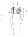
- FIG. 10 is an enlarged plan view showing a main part of a conventional analysis disc.
- FIG. 11 is an explanatory drawing showing image processing of a conventional analysis apparatus.
- FIGS. 1 to 8 embodiments of the present invention will be described below.
- FIG. 1 shows an analysis apparatus of the present invention.
- the configuration of a reproducing device 107 constituted of a microcomputer and an analysis disc 108 used for analysis instead of the optical disc 101 are different from those of the conventional art.
- the analysis disc 108 is configured so that a mixture of a sample and a reagent corresponding to a test item is set as an analysis object B on the optical disc 101 . Only on a position immediately in front of a reading area 109 in a rotation direction C, the reading area 109 having the analysis object B therein, a mark 110 F is recorded over the radial direction (the direction of arrow A) of the reading area.
- two analysis objects B are provided on the analysis disc 108 and the marks 110 F are formed immediately in front of the analysis objects B.
- FIG. 5 shows specific examples of the position of the analysis object B in the analysis disc 108 and the mark 110 F in the analysis disc 108 .
- the analysis object B is provided between a surface 108 a and a track 101 a of the analysis disc 108 .
- the mark 110 F is formed by printing ink 111 like a belt on the back of the optical disc 101 .
- reference numeral 112 a denotes a pit or a groove formed on the track 101 a which has been subjected to mirror-like finishing.
- Reference numeral 112 b denotes a land formed on the track 101 a which has been subjected to mirror-like finishing.
- the analysis object B may be provided between the track 101 a and a back 108 b of the analysis disc 108 .
- a pickup 103 traces the spiral track 101 a of the analysis disc 108 .
- a servo control circuit 106 drives a traverse motor 104 so that the track 101 a composed of pits or grooves and so on is traced according to the reproduction output of the pickup 103 . Further, the servo control circuit 106 detects the address information recorded on the track 101 a and drives a disc motor 102 with a constant linear velocity (CLV control).
- CLV control constant linear velocity
- the reproducing device 107 serving as an image processor is configured as below.
- the reproducing device 107 first accumulates image data, which has been read by the pickup 103 in time series, as trace data in a memory 113 . In this case, similar processing is performed on the two analysis objects B. Thus, referring to FIG. 5 , one of the analysis objects B will be discussed as an example to describe the contents of the processing.
- FIG. 4( a ) shows trace data.
- the pickup 103 traces first to ninth tracks in this order from above to below in FIG. 4( a ) for each rotation of the optical disc 101 , and accumulates the trace data in the memory 113 .
- a part of the analysis object B is positioned on the second track to the eighth track.
- Reference numerals V 2 to V 8 represent the resolution image data of the analysis object B.
- Reference numerals S 1 to S 9 represent trigger signals on respective track positions where the mark 110 F has been read.
- a first processing section 116 is constituted of a trigger circuit 114 for detecting a trigger signal in trace data having been read from the memory 113 and a switch circuit 115 for correcting the time axis of trace data in each track based on the detection output of the trigger circuit 114 .
- the first processing section 116 properly delays the timing to output the trace data, which has been read from the memory 113 , to the subsequent stage, moves the time axis of trace data in each track so that the positions of the trigger signals S 1 to S 9 are aligned with one another as show in FIG. 4( b ), and outputs image data D.
- the outputs of the trigger signals S 1 and S 3 to S 9 are delayed so as to be aligned with the position of the trigger signal S 2 .
- the trace data in each track that has been subjected to time base correction relative to the mark 110 F is accumulated in a second processing section 117 . Then, the trace data is outputted as reproduction image output. Further, when shape count is necessary as well as video acquisition of the analysis object, counting is performed in each unit area.
- time axes are aligned relative to the position of the mark 110 F, so that image data can be obtained with higher accuracy than the conventional art, in which time axes are aligned relative to address information.
- FIG. 6 shows an analysis disc of Embodiment 2.
- the mark 110 F is disposed only on a position immediately in front of the reading area 109 in the rotating direction C, the reading area 109 having the analysis object B therein.
- a mark 110 B identical to the mark 110 F is disposed just behind an analysis object B.
- the reproducing device 107 of the analysis apparatus performs time base correction so that the trigger signals S 1 to S 9 having read the mark 110 F are aligned with one another.
- the same effect as Embodiment 1 can be expected also by using an analysis disc 108 where the mark 110 F is absent and the mark 110 B is provided just behind the analysis object B, and a reproducing device 107 of the analysis apparatus performs time base correction so that trigger signals having read the mark 110 B are aligned with one another.
- the marks 110 F and 110 B are offset from the center of the disc and are disposed in parallel with the reading portion of the analysis target B. In this case, a distance between the mark and a sample is not so different between the inner edge and the outer edge of the disc. Thus, when a relatively large sample (several millimeters or more) is visualized, a distortion is small in the reproduction of an image.
- the mark 110 F, the mark 110 F and the mark 110 B, and the mark 110 B are all formed by printing as shown in FIG. 5( a ).
- the mark 110 F, the mark 110 F and the mark 110 B, and the mark 110 B can be similarly formed by providing a portion 118 , which has lost a mirror surface, on a part of the track 101 a having been subjected to mirror-like finishing.
- BCA is provided on a mirror surface of a DVD.
- the mark 110 F, the mark 110 F and the mark 110 B, and the mark 110 B can be similarly formed by providing an oddly shaped portion 119 such as a concave portion on a part of the outside of the analysis disc 108 .
- the disc is changed in shape to reflect light on a data track surface.
- the specific positions and ranges of the portion 118 , which has lost a mirror surface, and the oddly shaped portion 119 on the analysis disc 108 correspond to one of a position immediately in front of, a position in the front of or behind, and a position just behind the reading area 109 in the rotating direction, the reading area having the analysis object B therein.
- the positions and ranges are similar to those of the marks in the foregoing embodiments.
- An analysis apparatus which uses the analysis disc 108 having the portion 118 having lost a mirror surface or the oddly shaped portion 119 , is different from the foregoing embodiments only in that the portion 118 having lost a mirror surface or the oddly shaped portion 119 are read and trigger signals having detected mark positions are generated.
- FIGS. 5( b ) and 5 ( c ) the position of the analysis is object B on the analysis disc 108 is the same as that of FIG. 5( a ).
- the mark 110 F, the mark 110 F and the mark 110 B, and the mark 110 B are formed by printing, removing a mirror surface, or forming an odd shape.
- the mark may be provided on the pit, the groove 112 a, or the land 112 b of the analysis disc 108 .
- the mark is constituted of pits such as EFM and MFF.
- the mark is constituted of prepits, LPP (land prepits) (recorded as address information on a DVD-R/RW and engraved as prepits on lands between tracks, and to be specific, CAPA (prepits for the address on a DVD-RAM)) and so on. Modulation of some kind including a wobble is superimposed on a groove or a land.
- the specific position and range of the mark constituted of pits, grooves, or lands on the analysis disc 108 correspond to one of a position immediately in front of, a position in the front of or behind, or a position just behind the reading area 109 in the rotating direction, the reading area 109 having the analysis object B therein.
- the position and range are similar to those of the marks in the foregoing embodiments.
- An analysis apparatus which uses the analysis disc 108 having the mark constituted of pits, grooves, or lands, is different from the foregoing embodiments only in that the mark is read by the pickup 103 and trigger signals having detected mark positions are generated.
- the specific pattern of the mark is varied by modulating the mark so that the array position or analysis contents of the analysis object B can be identified on the analysis disc 108 .
- the analysis apparatus using the analysis disc 108 is configured as below.
- the analysis disc shown in FIG. 7 is configured using such an analysis apparatus, it is possible to conduct blood tests on two or more persons at the same time and manage test results for each person.
- the illustrated analysis disc 108 is divided broadly into four regions by marks 110 L, and three analysis objects B can be disposed in respective regions with marks 110 S.
- the marks 110 L and 110 S are formed so as to radially stretch from the center of the disc along the radial direction with different patterns, so that the analysis objects B can be managed.
- the reproducing device 107 of the analysis apparatus using the analysis disc 108 where the specific pattern of the mark is varied by performing modulation identifying the analysis contents of the analysis object B the reproducing device 107 being configured so as to manage image data on which the pickup 103 reads the mark and time base correction is performed relative to trigger signals having detected mark positions, and manage the kind of desired analysis object in a coordinated manner based on the specific pattern of the read mark. Thereafter, the contents of image processing, the counting method, the decision method, and so on are automatically processed according to the kind of analysis object.
- the kind of analyst object indicates analysis items such as cholesterol, erythrocyte, and leukocyte when a sample is blood.
- the reproducing device 107 serving as an image processor is configured as follows: regarding reading signals of the mark, visualization is performed to align time axes relative to the position of the mark, an image of the analysis object is obtained or shape count is performed, and the visualization results are managed in association with the reading area based on the specific pattern.
- a disc shown in FIG. 7 can be used as an analysis disc applicable to such an analysis apparatus.
- the kind of analysis object is changed in each region of the analysis disc, so that blood of one person can be tested and managed three times for four kinds of test items.
- the kind of analysis object can be changed in a region of the analysis disc. In this case, blood of two or more persons can be tested and managed for two or more test items on a single disc.
- the mark 110 F, the mark 110 F and the mark 110 B, and the mark 110 B may be provided as two or more marks in consideration of the occurrence of a reading error. For example, the order of marks from the closest to the analysis object B is modulated and recorded on a marker, and then the order is read, so that the function of the marker can be performed by interpolation even in the event of a reading error of the marker.
- the mark 110 F has marks 110 F 5 , 110 F 4 , . . . , and 110 F 1 at regular intervals of “5”, “4”, “3”, “2”, and “1” as the mark 110 F comes closer to the analysis object B, for example, even when the mark 110 F 2 of “2” is not read and missed, previously read “5”, “4”, and “3” are counted and the rule of intervals is understood, so that “2” can be generated without any trouble. Also when “1” is missed, “0” position is similarly expected and thus the function of a video acquisition trigger can be performed.
- CAV control reading is performed on an image of a sample.
- control is performed so that a disc has a constant rotation. Therefore, a travel distance is different between the inner edge and the outer edge for each hour.
- acquisition at regular intervals results in an image different from actual one.
- it is necessary to have different intervals of video acquisition between the inner edge and the outer edge. It is strictly necessary to have the same conditions as the video acquisition of CLV control.
- the mark intervals of the marker are provided regularly on the disc regardless of whether on the inner edge or the outer edge.
- a reading device synchronizes a reading cycle of an image with the mark intervals and acquires an image of a sample while keeping the synchronization.
- the method is used for a unit which changes the reading cycle according to a change in linear velocity of the disc.
- the present invention is applicable to other kinds of analysis.
- the present invention is applicable to analysis on drinking water such as tap water and analysis on water quality of a reservoir and so on.
- the track 101 a is provided above or below the analysis object B.
- the present invention can be implemented without providing the track 101 a in the region of the analysis object B.
- an analysis disc is used where a mark is recorded over the radial direction of a reading area, in which an analysis object is disposed, at least in front of or behind the reading area in the rotation direction, a pickup is provided which detects the mark and detection light from the analysis object disposed on the set analysis disc, and an image processor which performs video acquisition or shape count on the analysis object by performing video processing for aligning time axes relative to the position of the mark, on the analysis object and the reading signals of the mark, the analysis object being read in time series by the pickup which traces tracks.
- a pickup which detects the mark and detection light from the analysis object disposed on the set analysis disc
- an image processor which performs video acquisition or shape count on the analysis object by performing video processing for aligning time axes relative to the position of the mark, on the analysis object and the reading signals of the mark, the analysis object being read in time series by the pickup which traces tracks.
Priority Applications (1)
| Application Number | Priority Date | Filing Date | Title |
|---|---|---|---|
| US11/892,468 US7369218B2 (en) | 2002-03-14 | 2007-08-23 | Analysis disc with analysis object |
Applications Claiming Priority (2)
| Application Number | Priority Date | Filing Date | Title |
|---|---|---|---|
| JP2002069375A JP4194787B2 (ja) | 2002-03-14 | 2002-03-14 | 分析装置とそれに使用する分析用ディスク |
| PCT/JP2003/002806 WO2003076909A1 (fr) | 2002-03-14 | 2003-03-10 | Systeme d'analyse et disque d'analyse utilise dans ce systeme d'analyse |
Related Child Applications (1)
| Application Number | Title | Priority Date | Filing Date |
|---|---|---|---|
| US11/892,468 Division US7369218B2 (en) | 2002-03-14 | 2007-08-23 | Analysis disc with analysis object |
Publications (2)
| Publication Number | Publication Date |
|---|---|
| US20050169611A1 US20050169611A1 (en) | 2005-08-04 |
| US7333193B2 true US7333193B2 (en) | 2008-02-19 |
Family
ID=27800320
Family Applications (2)
| Application Number | Title | Priority Date | Filing Date |
|---|---|---|---|
| US10/507,412 Expired - Lifetime US7333193B2 (en) | 2002-03-14 | 2003-03-10 | Analysis apparatus irradiating detection light and reading state of analysis object |
| US11/892,468 Expired - Lifetime US7369218B2 (en) | 2002-03-14 | 2007-08-23 | Analysis disc with analysis object |
Family Applications After (1)
| Application Number | Title | Priority Date | Filing Date |
|---|---|---|---|
| US11/892,468 Expired - Lifetime US7369218B2 (en) | 2002-03-14 | 2007-08-23 | Analysis disc with analysis object |
Country Status (6)
| Country | Link |
|---|---|
| US (2) | US7333193B2 (ja) |
| EP (1) | EP1491875A4 (ja) |
| JP (1) | JP4194787B2 (ja) |
| CN (1) | CN1643365B (ja) |
| TW (1) | TWI273229B (ja) |
| WO (1) | WO2003076909A1 (ja) |
Families Citing this family (10)
| Publication number | Priority date | Publication date | Assignee | Title |
|---|---|---|---|---|
| JP4606833B2 (ja) * | 2003-10-07 | 2011-01-05 | パナソニック株式会社 | 粒状物判別方法 |
| JP4665902B2 (ja) | 2004-07-29 | 2011-04-06 | パナソニック株式会社 | 分析装置、分析用ディスクおよびそれらを備えた分析システム |
| JP4591195B2 (ja) * | 2005-05-19 | 2010-12-01 | ソニー株式会社 | バイオアッセイ用の基板と装置、並びに基板の製造方法 |
| KR100818274B1 (ko) | 2006-09-05 | 2008-04-01 | 삼성전자주식회사 | 미세유동 시스템 제어장치 및 그 방법, 및 미세유동 시스템 |
| JP5174627B2 (ja) | 2008-01-21 | 2013-04-03 | パナソニック株式会社 | 分析装置 |
| KR20110010922A (ko) * | 2009-07-27 | 2011-02-08 | 삼성전자주식회사 | 미세유동 장치, 이를 포함하는 미세유동 시스템 및 미세유동 장치의 기준각 검출 방법 |
| JP6205584B2 (ja) * | 2012-03-29 | 2017-10-04 | パナソニックIpマネジメント株式会社 | 試料保持担体およびそれを用いた蛍光検出システム、蛍光検出装置 |
| JP6120310B2 (ja) * | 2013-02-07 | 2017-04-26 | 国立研究開発法人産業技術総合研究所 | 微小構造物検出装置及び方法並びに検出用ディスク |
| US9545523B2 (en) | 2013-03-14 | 2017-01-17 | Zeltiq Aesthetics, Inc. | Multi-modality treatment systems, methods and apparatus for altering subcutaneous lipid-rich tissue |
| JP6237417B2 (ja) * | 2014-03-31 | 2017-11-29 | 株式会社Jvcケンウッド | 分析装置及び分析方法 |
Citations (8)
| Publication number | Priority date | Publication date | Assignee | Title |
|---|---|---|---|---|
| JPH03225278A (ja) | 1990-01-31 | 1991-10-04 | Idemitsu Petrochem Co Ltd | 液体試料分析用ディスク |
| WO1996009548A1 (en) | 1994-09-21 | 1996-03-28 | The University Court Of The University Of Glasgow | Apparatus and method for carrying out analysis of samples |
| WO1999009394A1 (en) | 1997-08-15 | 1999-02-25 | Alexion Pharmaceuticals, Inc. | Apparatus for performing assays at reaction sites |
| WO1999024822A1 (en) | 1997-11-12 | 1999-05-20 | Functional Genetics, Inc. | Rapid screening assay methods and devices |
| JP2001238674A (ja) | 2000-02-29 | 2001-09-04 | Nikon Corp | Dnaアレイ、dnaアレイ読み取り装置、及びdnaアレイ製造装置 |
| WO2002016037A1 (en) | 2000-08-21 | 2002-02-28 | Burstein Technologies, Inc | Methods and apparatus for optical disc data acquisition using physical synchronization markers |
| WO2002056311A2 (en) | 2001-01-11 | 2002-07-18 | Burstein Technologies Inc | Optical disc analysis system including related methods for biological and medical imaging |
| WO2002093167A1 (fr) | 2001-05-10 | 2002-11-21 | Kabushiki Kaisya Advance | Appareil d'examen de fluides corporels |
Family Cites Families (2)
| Publication number | Priority date | Publication date | Assignee | Title |
|---|---|---|---|---|
| AU5494900A (en) * | 1999-06-18 | 2001-01-09 | Gamera Bioscience Corporation | Devices and methods for the performance of miniaturized homogeneous assays |
| US7026131B2 (en) * | 2000-11-17 | 2006-04-11 | Nagaoka & Co., Ltd. | Methods and apparatus for blood typing with optical bio-discs |
-
2002
- 2002-03-14 JP JP2002069375A patent/JP4194787B2/ja not_active Expired - Fee Related
-
2003
- 2003-03-10 US US10/507,412 patent/US7333193B2/en not_active Expired - Lifetime
- 2003-03-10 CN CN03806064.7A patent/CN1643365B/zh not_active Expired - Fee Related
- 2003-03-10 WO PCT/JP2003/002806 patent/WO2003076909A1/ja active Application Filing
- 2003-03-10 EP EP03708525A patent/EP1491875A4/en not_active Withdrawn
- 2003-03-13 TW TW092105430A patent/TWI273229B/zh not_active IP Right Cessation
-
2007
- 2007-08-23 US US11/892,468 patent/US7369218B2/en not_active Expired - Lifetime
Patent Citations (10)
| Publication number | Priority date | Publication date | Assignee | Title |
|---|---|---|---|---|
| JPH03225278A (ja) | 1990-01-31 | 1991-10-04 | Idemitsu Petrochem Co Ltd | 液体試料分析用ディスク |
| WO1996009548A1 (en) | 1994-09-21 | 1996-03-28 | The University Court Of The University Of Glasgow | Apparatus and method for carrying out analysis of samples |
| WO1999009394A1 (en) | 1997-08-15 | 1999-02-25 | Alexion Pharmaceuticals, Inc. | Apparatus for performing assays at reaction sites |
| WO1999024822A1 (en) | 1997-11-12 | 1999-05-20 | Functional Genetics, Inc. | Rapid screening assay methods and devices |
| US5922617A (en) * | 1997-11-12 | 1999-07-13 | Functional Genetics, Inc. | Rapid screening assay methods and devices |
| JP2001522998A (ja) | 1997-11-12 | 2001-11-20 | ファンクショナル ジェネティクス,インコーポレイティド | 高速スクリーニング検査方法および装置 |
| JP2001238674A (ja) | 2000-02-29 | 2001-09-04 | Nikon Corp | Dnaアレイ、dnaアレイ読み取り装置、及びdnaアレイ製造装置 |
| WO2002016037A1 (en) | 2000-08-21 | 2002-02-28 | Burstein Technologies, Inc | Methods and apparatus for optical disc data acquisition using physical synchronization markers |
| WO2002056311A2 (en) | 2001-01-11 | 2002-07-18 | Burstein Technologies Inc | Optical disc analysis system including related methods for biological and medical imaging |
| WO2002093167A1 (fr) | 2001-05-10 | 2002-11-21 | Kabushiki Kaisya Advance | Appareil d'examen de fluides corporels |
Non-Patent Citations (1)
| Title |
|---|
| US 6,200,755, 03/2001, Virtanen (withdrawn) |
Also Published As
| Publication number | Publication date |
|---|---|
| CN1643365A (zh) | 2005-07-20 |
| WO2003076909A1 (fr) | 2003-09-18 |
| EP1491875A4 (en) | 2007-01-31 |
| JP4194787B2 (ja) | 2008-12-10 |
| EP1491875A1 (en) | 2004-12-29 |
| CN1643365B (zh) | 2010-04-14 |
| US7369218B2 (en) | 2008-05-06 |
| TW200306413A (en) | 2003-11-16 |
| TWI273229B (en) | 2007-02-11 |
| US20050169611A1 (en) | 2005-08-04 |
| JP2003270128A (ja) | 2003-09-25 |
| US20080007721A1 (en) | 2008-01-10 |
Similar Documents
| Publication | Publication Date | Title |
|---|---|---|
| US7369218B2 (en) | Analysis disc with analysis object | |
| US5848050A (en) | Optical disk having a continuous recording track formed of alternating land and groove revolutions | |
| JP3063596B2 (ja) | 光ディスク装置および光ディスク | |
| EP0874356B1 (en) | Optical disc discriminating system | |
| JP3021029B2 (ja) | 光磁気記録媒体の情報アクセス方法 | |
| US20060002262A1 (en) | Information recording method | |
| US20030202436A1 (en) | Recording disc and apparatus and method for reproducing recorded information | |
| US5170385A (en) | Recording medium with unembossed area indicating sector divisions | |
| EP1191529A2 (en) | Optical disk drive, and method for identifying optical disks mounted thereto | |
| JP2001034952A (ja) | 光ディスク及び光ディスク記録再生装置 | |
| GB2178218A (en) | Rotary recording medium having a guide track and recording and reproducing apparatus therefor | |
| JP2775956B2 (ja) | 記録媒体 | |
| EP1130579A2 (en) | Servo control apparatus, servo control method and information reproducing apparatus | |
| JP4358999B2 (ja) | 光学式記録媒体の記録装置 | |
| EP1225571A2 (en) | Pre-pit detecting apparatus | |
| KR100686066B1 (ko) | 광 기록매체의 제어 장치 | |
| EP1512959A1 (en) | Analysis device and analysis disc used for the same | |
| JP2773353B2 (ja) | データ記録トラック | |
| JP3073744B2 (ja) | 光ディスク媒体 | |
| JP3090925B2 (ja) | 光ディスク装置 | |
| KR100698105B1 (ko) | 광 기록매체의 랜드/그루브 트랙 판별 방법 및 장치 | |
| JP2000200438A (ja) | 光ディスク装置及び光ディスクトラッキング方法 | |
| JPH01130326A (ja) | 光デイスクの記録状況検出装置 | |
| JP2000200421A (ja) | 光ディスク装置 | |
| JPS63136358A (ja) | 光学式記録再生装置 |
Legal Events
| Date | Code | Title | Description |
|---|---|---|---|
| AS | Assignment |
Owner name: MATSUSHITA ELECTRIC INDUSTRIAL, CO., LTD., JAPAN Free format text: ASSIGNMENT OF ASSIGNORS INTEREST;ASSIGNORS:WAKITA, TSUGIO;FUJIMOTO, MITSUTERU;MIYAGAWA, SATOSHI;REEL/FRAME:016191/0073 Effective date: 20040907 |
|
| FEPP | Fee payment procedure |
Free format text: PAYOR NUMBER ASSIGNED (ORIGINAL EVENT CODE: ASPN); ENTITY STATUS OF PATENT OWNER: LARGE ENTITY |
|
| STCF | Information on status: patent grant |
Free format text: PATENTED CASE |
|
| FPAY | Fee payment |
Year of fee payment: 4 |
|
| AS | Assignment |
Owner name: PANASONIC CORPORATION, JAPAN Free format text: CHANGE OF NAME;ASSIGNOR:MATSUSHITA ELECTRIC INDUSTRIAL CO., LTD.;REEL/FRAME:032332/0082 Effective date: 20081001 |
|
| AS | Assignment |
Owner name: PANASONIC HEALTHCARE CO., LTD., JAPAN Free format text: ASSIGNMENT OF ASSIGNORS INTEREST;ASSIGNOR:PANASONIC CORPORATION;REEL/FRAME:032360/0795 Effective date: 20131127 |
|
| AS | Assignment |
Owner name: PANASONIC CORPORATION, JAPAN Free format text: ASSIGNMENT OF ASSIGNORS INTEREST;ASSIGNOR:PANASONIC HEALTHCARE CO., LTD.;REEL/FRAME:032480/0433 Effective date: 20140301 |
|
| AS | Assignment |
Owner name: PHC HOLDINGS CO., LTD., JAPAN Free format text: ASSIGNMENT OF ASSIGNORS INTEREST;ASSIGNOR:PANASONIC CORPORATION;REEL/FRAME:032785/0498 Effective date: 20140331 Owner name: PANASONIC HEALTHCARE HOLDINGS CO., LTD., JAPAN Free format text: CHANGE OF NAME;ASSIGNOR:PHC HOLDINGS CO., LTD.;REEL/FRAME:032785/0563 Effective date: 20140331 |
|
| FPAY | Fee payment |
Year of fee payment: 8 |
|
| AS | Assignment |
Owner name: PHC HOLDINGS CORPORATION, JAPAN Free format text: CHANGE OF NAME;ASSIGNOR:PANASONIC HEALTHCARE HOLDINGS CO., LTD.;REEL/FRAME:046459/0861 Effective date: 20180401 |
|
| MAFP | Maintenance fee payment |
Free format text: PAYMENT OF MAINTENANCE FEE, 12TH YEAR, LARGE ENTITY (ORIGINAL EVENT CODE: M1553); ENTITY STATUS OF PATENT OWNER: LARGE ENTITY Year of fee payment: 12 |