US7332121B2 - Thermoforming apparatus for producing shaped bodies of plastic sheet, and a method for producing them - Google Patents
Thermoforming apparatus for producing shaped bodies of plastic sheet, and a method for producing them Download PDFInfo
- Publication number
- US7332121B2 US7332121B2 US10/512,258 US51225805A US7332121B2 US 7332121 B2 US7332121 B2 US 7332121B2 US 51225805 A US51225805 A US 51225805A US 7332121 B2 US7332121 B2 US 7332121B2
- Authority
- US
- United States
- Prior art keywords
- tool table
- upper tool
- drive means
- intermediary
- stretch
- Prior art date
- Legal status (The legal status is an assumption and is not a legal conclusion. Google has not performed a legal analysis and makes no representation as to the accuracy of the status listed.)
- Expired - Fee Related, expires
Links
- 238000003856 thermoforming Methods 0.000 title claims abstract description 47
- 239000002985 plastic film Substances 0.000 title claims abstract description 27
- 238000004519 manufacturing process Methods 0.000 title claims abstract description 10
- 238000000034 method Methods 0.000 claims abstract description 9
- 238000009517 secondary packaging Methods 0.000 claims abstract description 6
- 230000007246 mechanism Effects 0.000 claims description 89
- 238000005520 cutting process Methods 0.000 claims description 14
- 230000008901 benefit Effects 0.000 description 6
- 230000005540 biological transmission Effects 0.000 description 6
- 230000001360 synchronised effect Effects 0.000 description 4
- 230000008878 coupling Effects 0.000 description 3
- 238000010168 coupling process Methods 0.000 description 3
- 238000005859 coupling reaction Methods 0.000 description 3
- 238000009966 trimming Methods 0.000 description 3
- 238000006073 displacement reaction Methods 0.000 description 2
- 238000004806 packaging method and process Methods 0.000 description 2
- 230000008569 process Effects 0.000 description 2
- 229910000831 Steel Inorganic materials 0.000 description 1
- 230000009471 action Effects 0.000 description 1
- 230000004913 activation Effects 0.000 description 1
- 230000006978 adaptation Effects 0.000 description 1
- 238000000137 annealing Methods 0.000 description 1
- 238000010276 construction Methods 0.000 description 1
- 238000001816 cooling Methods 0.000 description 1
- 230000009849 deactivation Effects 0.000 description 1
- 238000007599 discharging Methods 0.000 description 1
- 239000010720 hydraulic oil Substances 0.000 description 1
- 230000003100 immobilizing effect Effects 0.000 description 1
- 238000002347 injection Methods 0.000 description 1
- 239000007924 injection Substances 0.000 description 1
- 238000012423 maintenance Methods 0.000 description 1
- 239000011159 matrix material Substances 0.000 description 1
- 238000005457 optimization Methods 0.000 description 1
- 230000000717 retained effect Effects 0.000 description 1
- 239000000243 solution Substances 0.000 description 1
- 125000006850 spacer group Chemical group 0.000 description 1
- 239000010959 steel Substances 0.000 description 1
- 230000002195 synergetic effect Effects 0.000 description 1
- 239000012815 thermoplastic material Substances 0.000 description 1
Images


Classifications
-
- B—PERFORMING OPERATIONS; TRANSPORTING
- B29—WORKING OF PLASTICS; WORKING OF SUBSTANCES IN A PLASTIC STATE IN GENERAL
- B29C—SHAPING OR JOINING OF PLASTICS; SHAPING OF MATERIAL IN A PLASTIC STATE, NOT OTHERWISE PROVIDED FOR; AFTER-TREATMENT OF THE SHAPED PRODUCTS, e.g. REPAIRING
- B29C51/00—Shaping by thermoforming, i.e. shaping sheets or sheet like preforms after heating, e.g. shaping sheets in matched moulds or by deep-drawing; Apparatus therefor
- B29C51/04—Combined thermoforming and prestretching, e.g. biaxial stretching
-
- B—PERFORMING OPERATIONS; TRANSPORTING
- B29—WORKING OF PLASTICS; WORKING OF SUBSTANCES IN A PLASTIC STATE IN GENERAL
- B29C—SHAPING OR JOINING OF PLASTICS; SHAPING OF MATERIAL IN A PLASTIC STATE, NOT OTHERWISE PROVIDED FOR; AFTER-TREATMENT OF THE SHAPED PRODUCTS, e.g. REPAIRING
- B29C51/00—Shaping by thermoforming, i.e. shaping sheets or sheet like preforms after heating, e.g. shaping sheets in matched moulds or by deep-drawing; Apparatus therefor
- B29C51/18—Thermoforming apparatus
- B29C51/20—Thermoforming apparatus having movable moulds or mould parts
- B29C51/22—Thermoforming apparatus having movable moulds or mould parts rotatable about an axis
-
- B—PERFORMING OPERATIONS; TRANSPORTING
- B29—WORKING OF PLASTICS; WORKING OF SUBSTANCES IN A PLASTIC STATE IN GENERAL
- B29C—SHAPING OR JOINING OF PLASTICS; SHAPING OF MATERIAL IN A PLASTIC STATE, NOT OTHERWISE PROVIDED FOR; AFTER-TREATMENT OF THE SHAPED PRODUCTS, e.g. REPAIRING
- B29C51/00—Shaping by thermoforming, i.e. shaping sheets or sheet like preforms after heating, e.g. shaping sheets in matched moulds or by deep-drawing; Apparatus therefor
- B29C51/26—Component parts, details or accessories; Auxiliary operations
- B29C51/30—Moulds
- B29C51/38—Opening, closing or clamping means
-
- B—PERFORMING OPERATIONS; TRANSPORTING
- B29—WORKING OF PLASTICS; WORKING OF SUBSTANCES IN A PLASTIC STATE IN GENERAL
- B29C—SHAPING OR JOINING OF PLASTICS; SHAPING OF MATERIAL IN A PLASTIC STATE, NOT OTHERWISE PROVIDED FOR; AFTER-TREATMENT OF THE SHAPED PRODUCTS, e.g. REPAIRING
- B29C51/00—Shaping by thermoforming, i.e. shaping sheets or sheet like preforms after heating, e.g. shaping sheets in matched moulds or by deep-drawing; Apparatus therefor
- B29C51/26—Component parts, details or accessories; Auxiliary operations
- B29C51/46—Measuring, controlling or regulating
-
- B—PERFORMING OPERATIONS; TRANSPORTING
- B29—WORKING OF PLASTICS; WORKING OF SUBSTANCES IN A PLASTIC STATE IN GENERAL
- B29C—SHAPING OR JOINING OF PLASTICS; SHAPING OF MATERIAL IN A PLASTIC STATE, NOT OTHERWISE PROVIDED FOR; AFTER-TREATMENT OF THE SHAPED PRODUCTS, e.g. REPAIRING
- B29C2791/00—Shaping characteristics in general
- B29C2791/002—Making articles of definite length, i.e. discrete articles
-
- B—PERFORMING OPERATIONS; TRANSPORTING
- B29—WORKING OF PLASTICS; WORKING OF SUBSTANCES IN A PLASTIC STATE IN GENERAL
- B29C—SHAPING OR JOINING OF PLASTICS; SHAPING OF MATERIAL IN A PLASTIC STATE, NOT OTHERWISE PROVIDED FOR; AFTER-TREATMENT OF THE SHAPED PRODUCTS, e.g. REPAIRING
- B29C2791/00—Shaping characteristics in general
- B29C2791/004—Shaping under special conditions
- B29C2791/006—Using vacuum
-
- B—PERFORMING OPERATIONS; TRANSPORTING
- B29—WORKING OF PLASTICS; WORKING OF SUBSTANCES IN A PLASTIC STATE IN GENERAL
- B29C—SHAPING OR JOINING OF PLASTICS; SHAPING OF MATERIAL IN A PLASTIC STATE, NOT OTHERWISE PROVIDED FOR; AFTER-TREATMENT OF THE SHAPED PRODUCTS, e.g. REPAIRING
- B29C2791/00—Shaping characteristics in general
- B29C2791/004—Shaping under special conditions
- B29C2791/007—Using fluid under pressure
-
- B—PERFORMING OPERATIONS; TRANSPORTING
- B29—WORKING OF PLASTICS; WORKING OF SUBSTANCES IN A PLASTIC STATE IN GENERAL
- B29C—SHAPING OR JOINING OF PLASTICS; SHAPING OF MATERIAL IN A PLASTIC STATE, NOT OTHERWISE PROVIDED FOR; AFTER-TREATMENT OF THE SHAPED PRODUCTS, e.g. REPAIRING
- B29C2793/00—Shaping techniques involving a cutting or machining operation
- B29C2793/009—Shaping techniques involving a cutting or machining operation after shaping
-
- B—PERFORMING OPERATIONS; TRANSPORTING
- B29—WORKING OF PLASTICS; WORKING OF SUBSTANCES IN A PLASTIC STATE IN GENERAL
- B29C—SHAPING OR JOINING OF PLASTICS; SHAPING OF MATERIAL IN A PLASTIC STATE, NOT OTHERWISE PROVIDED FOR; AFTER-TREATMENT OF THE SHAPED PRODUCTS, e.g. REPAIRING
- B29C35/00—Heating, cooling or curing, e.g. crosslinking or vulcanising; Apparatus therefor
- B29C35/16—Cooling
-
- B—PERFORMING OPERATIONS; TRANSPORTING
- B29—WORKING OF PLASTICS; WORKING OF SUBSTANCES IN A PLASTIC STATE IN GENERAL
- B29C—SHAPING OR JOINING OF PLASTICS; SHAPING OF MATERIAL IN A PLASTIC STATE, NOT OTHERWISE PROVIDED FOR; AFTER-TREATMENT OF THE SHAPED PRODUCTS, e.g. REPAIRING
- B29C51/00—Shaping by thermoforming, i.e. shaping sheets or sheet like preforms after heating, e.g. shaping sheets in matched moulds or by deep-drawing; Apparatus therefor
- B29C51/26—Component parts, details or accessories; Auxiliary operations
- B29C51/42—Heating or cooling
- B29C51/428—Heating or cooling of moulds or mould parts
-
- B—PERFORMING OPERATIONS; TRANSPORTING
- B29—WORKING OF PLASTICS; WORKING OF SUBSTANCES IN A PLASTIC STATE IN GENERAL
- B29C—SHAPING OR JOINING OF PLASTICS; SHAPING OF MATERIAL IN A PLASTIC STATE, NOT OTHERWISE PROVIDED FOR; AFTER-TREATMENT OF THE SHAPED PRODUCTS, e.g. REPAIRING
- B29C51/00—Shaping by thermoforming, i.e. shaping sheets or sheet like preforms after heating, e.g. shaping sheets in matched moulds or by deep-drawing; Apparatus therefor
- B29C51/26—Component parts, details or accessories; Auxiliary operations
- B29C51/44—Removing or ejecting moulded articles
- B29C51/445—Removing or ejecting moulded articles from a support after moulding, e.g. by cutting
-
- B—PERFORMING OPERATIONS; TRANSPORTING
- B29—WORKING OF PLASTICS; WORKING OF SUBSTANCES IN A PLASTIC STATE IN GENERAL
- B29K—INDEXING SCHEME ASSOCIATED WITH SUBCLASSES B29B, B29C OR B29D, RELATING TO MOULDING MATERIALS OR TO MATERIALS FOR MOULDS, REINFORCEMENTS, FILLERS OR PREFORMED PARTS, e.g. INSERTS
- B29K2023/00—Use of polyalkenes or derivatives thereof as moulding material
- B29K2023/10—Polymers of propylene
- B29K2023/12—PP, i.e. polypropylene
-
- B—PERFORMING OPERATIONS; TRANSPORTING
- B29—WORKING OF PLASTICS; WORKING OF SUBSTANCES IN A PLASTIC STATE IN GENERAL
- B29K—INDEXING SCHEME ASSOCIATED WITH SUBCLASSES B29B, B29C OR B29D, RELATING TO MOULDING MATERIALS OR TO MATERIALS FOR MOULDS, REINFORCEMENTS, FILLERS OR PREFORMED PARTS, e.g. INSERTS
- B29K2025/00—Use of polymers of vinyl-aromatic compounds or derivatives thereof as moulding material
-
- B—PERFORMING OPERATIONS; TRANSPORTING
- B29—WORKING OF PLASTICS; WORKING OF SUBSTANCES IN A PLASTIC STATE IN GENERAL
- B29K—INDEXING SCHEME ASSOCIATED WITH SUBCLASSES B29B, B29C OR B29D, RELATING TO MOULDING MATERIALS OR TO MATERIALS FOR MOULDS, REINFORCEMENTS, FILLERS OR PREFORMED PARTS, e.g. INSERTS
- B29K2027/00—Use of polyvinylhalogenides or derivatives thereof as moulding material
- B29K2027/06—PVC, i.e. polyvinylchloride
-
- B—PERFORMING OPERATIONS; TRANSPORTING
- B29—WORKING OF PLASTICS; WORKING OF SUBSTANCES IN A PLASTIC STATE IN GENERAL
- B29K—INDEXING SCHEME ASSOCIATED WITH SUBCLASSES B29B, B29C OR B29D, RELATING TO MOULDING MATERIALS OR TO MATERIALS FOR MOULDS, REINFORCEMENTS, FILLERS OR PREFORMED PARTS, e.g. INSERTS
- B29K2055/00—Use of specific polymers obtained by polymerisation reactions only involving carbon-to-carbon unsaturated bonds, not provided for in a single one of main groups B29K2023/00 - B29K2049/00, e.g. having a vinyl group, as moulding material
- B29K2055/02—ABS polymers, i.e. acrylonitrile-butadiene-styrene polymers
-
- B—PERFORMING OPERATIONS; TRANSPORTING
- B29—WORKING OF PLASTICS; WORKING OF SUBSTANCES IN A PLASTIC STATE IN GENERAL
- B29K—INDEXING SCHEME ASSOCIATED WITH SUBCLASSES B29B, B29C OR B29D, RELATING TO MOULDING MATERIALS OR TO MATERIALS FOR MOULDS, REINFORCEMENTS, FILLERS OR PREFORMED PARTS, e.g. INSERTS
- B29K2067/00—Use of polyesters or derivatives thereof, as moulding material
-
- B—PERFORMING OPERATIONS; TRANSPORTING
- B29—WORKING OF PLASTICS; WORKING OF SUBSTANCES IN A PLASTIC STATE IN GENERAL
- B29L—INDEXING SCHEME ASSOCIATED WITH SUBCLASS B29C, RELATING TO PARTICULAR ARTICLES
- B29L2031/00—Other particular articles
- B29L2031/56—Stoppers or lids for bottles, jars, or the like, e.g. closures
- B29L2031/565—Stoppers or lids for bottles, jars, or the like, e.g. closures for containers
-
- B—PERFORMING OPERATIONS; TRANSPORTING
- B29—WORKING OF PLASTICS; WORKING OF SUBSTANCES IN A PLASTIC STATE IN GENERAL
- B29L—INDEXING SCHEME ASSOCIATED WITH SUBCLASS B29C, RELATING TO PARTICULAR ARTICLES
- B29L2031/00—Other particular articles
- B29L2031/712—Containers; Packaging elements or accessories, Packages
- B29L2031/7132—Bowls, Cups, Glasses
-
- B—PERFORMING OPERATIONS; TRANSPORTING
- B29—WORKING OF PLASTICS; WORKING OF SUBSTANCES IN A PLASTIC STATE IN GENERAL
- B29L—INDEXING SCHEME ASSOCIATED WITH SUBCLASS B29C, RELATING TO PARTICULAR ARTICLES
- B29L2031/00—Other particular articles
- B29L2031/712—Containers; Packaging elements or accessories, Packages
- B29L2031/7162—Boxes, cartons, cases
Definitions
- the present invention relates to a thermoforming apparatus for producing shaped bodies of plastic sheet, such as cups, containers, lids, food packagings or the like, comprising a forming station with a two-part forming tool, in accordance with the preamble of claim 1 , as well as a method for producing such shaped bodies in accordance with the preamble of claim 7 .
- Thermoforming apparatus have in practice become known in different variants and embodiments.
- a two-part forming tool is used for manufacturing container-type articles or shaped bodies of thermoplastic material.
- One forming tool half, the so-called upper tool is attached to the upper tool table and generally connected, together with the latter, with the frame or stand of the thermoforming apparatus in an adjustably fixed manner, so that the upper tool may be adjusted to the respective shaped body to be produced.
- the other forming tool half, the so-called lower tool is movably guided in the frame or stand of the thermoforming apparatus.
- the forming tool halves i.e., the upper and lower tools
- the forming tool halves are arranged in a mutually facing, closed position.
- a plastic sheet is arranged which is usually pre-heated and thus has good ductility, and which is mostly supplied intermittently from a supply reel in the form of a sheet web.
- the plastic sheet is clamped between the upper and lower tools and thus immobilized. Then the plastic sheet is pressed into the cavities of the lower tool by the pre-stretch means of the upper tool, while the rim of the shaped body to be produced continues to be clampingly retained between the upper and lower tools.
- the sheet By generating a vacuum in the cavities, or by injection of air, the sheet applies itself against the inner walls of the cavities in the lower tool and thereby assumes the desired shape.
- the shaped bodies are severed from the plastic sheet.
- the lower tool is moved upwards by about the amount of the sheet thickness.
- Corresponding cutting edges of the two-part forming tool cut the individual shaped bodies from the sheet web.
- the remaining sheet matrix is, in turn, usually supplied intermittently to a reeling unit.
- the lower tool In order to remove the shaped bodies from the cavities, the lower tool is subsequently moved away from the upper tool while being rotated about its longitudinal axis such that the lower tool faces a stacking means, and the shaped bodies may thus be transferred to the stacking means.
- thermoforming apparatus as known from practice are described, e.g., in U.S. Pat. No. 6,135,756 or DE 33 46 628 A1.
- thermoforming apparatus do, however, have the essential economical drawback of only low cycle frequencies in the order, e.g., of up to 30 cycles per minute being achievable. Higher cycle frequencies are not possible without damage to the moved components. These low cycle frequencies are, however, not acceptable any more in view of the cost pressure nowadays prevailing.
- thermoforming apparatus described in DE 33 46 628 A1 specifically operates with a two-part forming tool, with the upper tool being fixedly attached to the stand, and the lower tool being movable.
- the lower tool For opening and closing, the lower tool is aligned towards the upper tool and away from it and at the same time towards a stacking means, and oriented away from the latter back to the upper tool in a combined lifting and rotating movement.
- the lifting and rotating movement of the lower tool is produced by a cam disc/toggle joint drive.
- the lower tool is to be displaced vertically and at the same time rotated about its own longitudinal axis.
- thermoforming apparatus in accordance with DE 33 46 628 A1
- a toggle joint mechanism in conjunction with a cam disc drive employed in the thermoforming apparatus known from DE 33 46 628 A1 has a very complex configuration. Even the cam disc drive mechanism itself already exhibits the inherent drawback that it is only capable of transmitting limited forces. In addition, high cycle frequencies cannot be achieved with a cam disc drive mechanism. Cam disc drive mechanisms furthermore tend to wear rapidly, so that they have to be maintenanced frequently, which raises the operating costs of such a thermoforming apparatus in an unacceptable degree. Moreover the presently discussed thermoforming apparatus in accordance with DE 33 46 628 A1 and its complex toggle joint mechanism includes another group of components which inherently also only allows for low cycle frequencies.
- thermoforming apparatus in accordance with U.S. Pat. No. 6,135,756 specifically also comprises a two-part forming tool.
- the guide means is here, as well, combined with the drive means of the lower tool table, or lower tool, and generates a combined lifting and rotating movement of the lower tool through the intermediary of a cam disc crank drive, with two cam disc crank drives being arranged on respective outer end faces of the lower tool.
- the lower tool has at its outer sides three journals each, which move in the associated grooved cams on the stand. These grooved cams have an extremely complex geometry and are adapted such that during opening of the forming tool, the lower tool may be moved downwardly away from the upper tool and rotated in order to be able to orient it towards a stacking means and again rotate it away from the latter.
- the drive mechanism for the pre-stretch means in U.S. Pat. No. 6,135,756 is described as a combination of rack and gear.
- the high cycle frequencies demanded for an economical operation of a present-day thermoforming apparatus Namely, not only high cycle frequencies in closing and opening the forming tool are required for lastingly achieving a repeatable cycle frequency, but the lifting movement of the pre-stretch means must in parallel be increased in at least a same degree in order to operate the pre-stretch means in a same cycle as the forming tool.
- pre-stretch means drive mechanisms are known in practical use where the pre-stretch means are driven through the intermediary of spherical roller spindles. With such spherical roller spindles, the demanded high cycle frequencies can not be attained. In addition, spherical roller spindles are too expensive, require frequent maintenance, and have long down times as a further drawback.
- thermoforming apparatus in such a way that substantially higher cycle frequencies may be achieved, and an economical operation of thermoforming apparatus thus improved becomes possible.
- object of the present invention propose an economical method for producing shaped bodies of plastic sheet.
- thermoforming apparatus for producing shaped bodies of plastic sheet, such as cups, containers, lids, food packagings or the like, comprising a forming station with a two-part forming tool.
- the two-part forming tool comprises an upper tool table adapted to be adjustably fixed and having an upper tool with pre-stretch means movably mounted therein, and a movable lower tool table having a lower tool with cavities.
- the movable lower tool table is guided through the intermediary of guide means and capable of being approached to the upper tool table and moved away from it by drive means.
- the upper tool table includes associated first drive means for adjusting the upper tool table in its position relative to the upper dead center of the lower tool table in correspondence with the respective shaped body to be produced, and that the upper tool table includes associated second drive means for driving the pre-stretch means movably mounted in the upper tool.
- uncoupling the drive mechanism of the pre-stretch means in accordance with the invention by correspondingly providing separate drive means therefor as well as further separate drive means for adjusting or setting the upper tool in accordance with the shaped bodies to be produced prior to finally immobilizing it before the start of the respective production process provides the advantage that these two drive mechanisms may be optimized independently of each other.
- the separate pre-stretch means drive mechanism may be selected with a view to the demanded high cycle frequency and optimized in this respect.
- the first drive means for adjusting the upper tool table have the form of an electrical servomotor.
- This provides the advantageous possibility of accurate regulation, wherein its speed profile may be selected freely.
- it is possible to achieve both fast delivery movements for overcoming long adjusting distances, as well as particularly slow and accurate delivery movements for accurately setting the upper tool table in the millimeter or even tenth-of-millimeter range, depending on the desired precision.
- Low-cost electrical servomotors are moreover commercially available in any demanded design variant.
- thermoforming apparatus in accordance with the invention, it is provided that these first drive means cooperate via a synchronization shaft with e.g., worm gears/gears arranged thereon with two associated actuating spindles which, in turn, act on the upper tool table such that the latter may be moved up and down in its horizontal orientation, so that the upper tool table may be adjusted to the respective shaped body to be produced.
- a synchronization shaft with e.g., worm gears/gears arranged thereon with two associated actuating spindles which, in turn, act on the upper tool table such that the latter may be moved up and down in its horizontal orientation, so that the upper tool table may be adjusted to the respective shaped body to be produced.
- the second drive means of the upper tool table include a hydraulic drive mechanism or a crank drive driven through the intermediary of an electric servomotor for driving the pre-stretch means.
- particularly high cycle frequencies may be achieved. These high cycle frequencies may be at least 40 cycles, 50 cycles or more cycles.
- a hydraulic drive mechanism of the pre-stretch means it is moreover advantageously possible to achieve pre-stretch means forces of at least 40 kN with a work stroke of at least 120 mm and a moved mass of at least 200 kg, with the time for covering the work stroke of 120 mm being less than 200 ms.
- the latter acts on the pre-stretch means in the upper tool via a thrust bar, a rocking lever, and a forcing lever, which represents a particularly simple constructive solution.
- the rocking lever it is here provided for the rocking lever to have a shiftably designed fulcrum, so that its lever arms, and accordingly its force relations, may be adapted to the respective application.
- Actuation of the pre-stretch means via a thrust bar, a rocking lever, and a forcing lever permits to position the second drive mechanisms externally of the range of the upper tool, in a particularly advantageous manner not directly above it, so that when a hydraulic drive mechanism is employed, a slight leakage of hydraulic oil—which may not always be excluded completely—is not particularly significant as it advantageously can not drip down onto the sheet web.
- this second drive mechanism may be arranged laterally from the upper tool table such that the second drive mechanism is moved jointly with the upper tool table and thus not moved relative to the latter, so that the second drive mechanism exclusively controls the movement of the pre-stretch means and thus may be optimized particularly advantageously with regard to high cycle frequencies.
- shifting the fulcrum may be utilized for adjusting a variable stroke of the pre-stretch means. Shifting the fulcrum advantageously results in a constant stroke of the drive mechanism and a continuous adaptation of the stroke of the pre-stretch means, so that the upper dead center of the pre-stretch means remains constant, and the bottom dead center may be adapted as a function of the height of a product or shaped body.
- the pre-stretch means may be driven through the intermediary of the second drive means such that a stroke of at least 120 mm or more may be performed in less than 300 ms, preferably less than 200 ms. Cycle frequencies of more than 60 cycles per minute may thus advantageously be realized, so that with a thermoforming apparatus in accordance with the invention providing, e.g., a crank drive for a linearly guided lower tool table, it is altogether possible to achieve high cycle frequencies that had hitherto been thought to be unattainable.
- FIG. 1 a top view of an embodiment of a thermoforming apparatus in accordance with the invention
- FIG. 2 is a side view of the exemplary embodiment of a thermoforming apparatus in accordance with the invention as represented in FIG. 1 ;
- FIG. 3 is a laterally viewed detail of the drive mechanism for rotating the guide rail assembly of the variant of a thermoforming apparatus in accordance with the invention as shown in FIGS. 1 and 2 ;
- FIG. 4 a sectional view along line X-X of FIG. 3 ;
- FIG. 5 represents the variant shown in FIGS. 1 through 4 in an obliquely positioned operational arrangement
- FIG. 6 is a schematically simplified drawing of an exemplary embodiment of a drive mechanism in accordance with the invention for actuating the pre-stretch means in the thermoforming apparatus of the invention in accordance with FIG. 1 through 5 ;
- FIG. 7 is a schematically simplified drawing of an exemplary embodiment visualizing a possible design of the drive mechanism shown in FIG. 6 ;
- FIG. 8 shows an alternative embodiment of the pre-stretch means drive mechanism in accordance with the invention of the thermoforming apparatus of FIGS. 1 through 5 ;
- FIG. 9 represents another variant of the alternatives of pre-stretch means drive mechanisms as shown in FIG. 6 through 8 , with the pre-stretch means in the home position;
- FIG. 10 represents the embodiment of a pre-stretch means drive mechanism as shown in FIG. 9 , with the pre-stretch means in the extended condition;
- FIG. 11 shows another alternative transmission structure for the variants of pre-stretch means drive mechanisms as shown in FIGS. 6 through 10 .
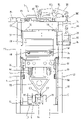
- FIG. 1 represents an exemplary embodiment of a thermoforming apparatus 1 in accordance with the invention in a front view.
- the movable component groups of the thermoforming apparatus 1 are arranged in a stand 2 .
- the stand 2 may, for instance, be constructed in the form of stand panels of steel sheet which are stress-relieved by annealing.
- the crankshaft drive mechanism 6 is in the presently represented variant driven by an electric servomotor 8 . Its drive force is transmitted via a belt 10 and pulleys 12 and 14 , which is more clearly visible particularly in the side view of FIG. 2 .
- the crankshaft drive mechanism 6 is mounted symmetrically on both sides in relatively short lever arms 16 , with the lever arms 16 in turn being linked to a bracket 18 mounted on the cross-member 4 .
- the two-part forming tool 20 of the forming station of the thermoforming apparatus 1 is represented in the closed condition approximately in the center of the drawing.
- a cross-member 24 visible in the upper section of FIG. 1 and FIG. 2 connects the two stand panels 2 above the two-part forming tool 20 and serves as a base for a drive mechanism 26 for adjusting the position of the upper tool table 28 with the upper tool 30 attached thereto.
- the drive mechanism 26 for adjusting the position of the upper tool table 28 may, e.g., have the form of a precision lifting mechanism with backlash compensation.
- a lower tool table 32 supports the lower tool 34 and is arranged between the rotatable guide rails 38 of the rotatable guide rail assembly 40 (cf. FIGS. 3 and 4 ) of the guide means 42 through the intermediary of correspondingly designed linear guides 36 .
- ejector cylinders 44 and the upper connecting rod bearings 46 are attached.
- a chain transport means 48 is shown whereby the plastic sheet 50 is supplied to the two-part forming tool 20 and transported off following forming and trimming out of the shaped bodies that are not shown here any more, with the plastic sheet 50 being tensioned by correspondingly suitable means in the range of the two-part forming tool 20 , preferably bidirectionally.
- the upper tool table 28 is guided in correspondingly designed linear guides 52 between the stand panels 2 .
- the lower tool 34 may, e.g., have a mounting surface of 490 mm ⁇ 1040 mm.
- four rows of eight cavities each for 32 shaped bodies may be realized at a diameter of the shaped bodies of about 75 mm. This amounts to a total die-cutting length of all edges to be severed of 7640 mm, necessitating a total die-cutting force of about 400 kN.
- the upper tool 30 is fastened to the upper tool table 28 , for example with the aid of spacers (not shown).
- Guide rails (not shown) facilitate mounting of the tools.
- a backlash compensation 54 serves for compensating play, e.g., during precision lifting 26 of the upper tool table 28 .
- the linear guides 36 for the lower tool table 32 have a play-free adjustment and ensure accurate guiding of the lower tool 34 .
- the linear guides 52 of the upper tool table 28 include slideways (not shown) which may be adjusted without play.
- the ejector drive means 44 positioned underneath the lower tool table 32 , for the ejectors 56 visible in FIG. 2 in a fragmentary sectional view, include two pneumatic cylinders with stroke-arresting means.
- the connecting rod 58 driven by the crankshaft drive mechanism 6 which may also be referred to as a driving rod for driving the lifting stroke of the lower tool table 32 , has the form of a triangle or of a Y in the presently represented variant.
- the connecting rod 58 is linked to the eccentric shaft portion 62 of the crankshaft drive mechanism 6 through a first connecting rod portion 60 .
- the two upwardly directed arms 64 of the Y-shaped connecting rod 58 in the views of FIGS. 1 and 2 are linked to the connecting rod bearings 46 of the lower tool table 32 .
- These two upper connecting rod bearings 46 here have an arrangement, if possible, where a flexure of the lower tool table 32 as well as its proper weight may be kept as low as possible.
- the Y-shaped connecting rod 58 advantageously has only one bearing at the lower connecting rod portion 60 of the presently represented variant, so that even one crank drive mechanism is sufficient.
- crankshaft drive mechanism 6 is mounted in two locations so as to better resist flexure.
- the respective crank bearings may be split for the purpose of easier mounting.
- the crankshaft drive mechanism 6 is centrally mounted in lever arms 16 forming a kind of double rocker. The latter in turn is mounted on the cross-member 4 by its right side through the intermediary of the bracket 18 . On the left side of this double rocker, the die-cutting drive mechanism 64 attacks.
- the die-cutting drive mechanism 64 consists, e.g., of a hydraulic cylinder and an associated hydraulic system for generating with the aid of the hydraulic cylinder an abrupt cutting stroke that is transmitted via the double rocker 16 , the crankshaft drive mechanism 6 , the connecting rod 58 , and the bearings 46 to the lower tool table 32 and thus to the lower tool 34 .
- the drive mechanism of the crankshaft drive mechanism 6 may—as was already mentioned above—include as the lifting drive mechanism a servomotor 8 which acts on the crankshaft drive mechanism 6 via transmission, toothed belt, ladder chain drive, or the like with little play. Closing and opening of the two-part forming tool 20 then correspond to respective 160-degree rotations at the crank shaft.
- the pivoted levers 38 for rotatably accommodating the lower tool table 32 which were already represented in FIGS. 1 and 2 , include in the presently represented variant, e.g., the pivoted lever lateral guides 66 having the form of cam rollers as represented in FIG. 3 .
- the lateral guide members 66 of the pivoted levers 38 having, e.g., the form of cam rollers, run on hardened rails (not shown) and may be adjusted free from play for accurately guiding the lower tool 34 .
- one driving rod 68 each is provided on either side of the lower tool table 32 .
- a drive mechanism 70 for generating the rotating movement of the lower tool 34 via the rotatable guide rails 38 it is possible to provide a driving rod pivotal drive mechanism 68 acting on both guide rails 38 which may be driven, e.g., by a geared servomotor 72 and a synchronized shaft 74 .
- a pivoted lever stop 76 in accordance with the representation of FIG. 3 is provided. This stop 76 for the pivoted lever 38 may be adjusted for accurately positioning the lower tool 32 .
- the drive mechanism 84 for adjusting the upper tool table 28 which may, e.g., have the form of a precision drive, serves not only for adjusting the die-cutting stroke, for example, but may also be employed for activation or deactivation of the die-cutting stroke.
- Two threaded spindles 78 barely visible in FIGS. 1 and 2 are driven, e.g., through worm gears 80 via a synchronized shaft 82 through the intermediary of a geared motor 84 .
- two backlash compensations 54 exemplarily having the form of pneumatic bellows cylinders are capable of drawing the upper tool table 28 upwardly through the intermediary of drawbars (not shown) so as to compensate for backlash between spindle and nut.
- a pre-stretch unit 86 is provided.
- the presently represented variant of the pre-stretch unit 86 includes, i.a., a pre-stretch means drive mechanism 88 having the form of a servomotor, which is coupled to the pre-stretch means plate 90 and the pre-stretch means 92 arranged thereon via a toothed belt drive not shown in FIG. 2 and a planetary roller threaded drive and the nut thereof through releasable connections.
- This pre-stretch means drive mechanism may also include a highly dynamic servomotor 88 .
- the latter may include a console 94 supporting a hydraulic cylinder 96 as the pre-stretch means drive mechanism.
- the hydraulic cylinder 96 is linearly displaced with the console 94 together with the upper tool table 28 while stationary relative to the latter. The distance between the hydraulic cylinder 96 and the upper tool table 28 thus remains permanently constant.
- the hydraulic cylinder 96 is encapsulated by a housing 98 , so that hydraulic oil cannot spill even in the event of minor leakages.
- a thrust bar 100 is linked to the hydraulic cylinder 96 in accordance with the representation in FIG.
- the rocking lever 102 is pivoted through the intermediary of a bearing mount 104 .
- the bearing mount 104 attacks at the upper tool table 28 via a suitable bracket.
- the pre-stretch means rod 106 is linked which is connected with the pre-stretch means plate 90 and the pre-stretch means 92 attached to the latter.
- the hydraulic cylinder 96 for driving the pre-stretch means 92 may include a servo control containing a programmable control for the stroke of the cylinder 96 .
- the necessary hydraulic unit may be positioned inside the bottom part of the machine.
- the pre-stretch means rod 106 may be connected with the pre-stretch means plate 90 in the upper tool 30 via a compensating coupling.
- the housing 98 for the hydraulic cylinder 96 not only serves for entrapping any leakages, but may also support the servo control and moreover contain sensors or the like in order to report any occurring leakages, and may be provided with means for discharging such leakages. The same also applies to the hydraulic conduits.
- the thermoforming apparatus 1 of the invention may be associated with a stacking means 108 for receiving, stacking and transporting the completed shaped bodies following ejection from the cavities of the lower tool 34 .
- the stacking means 108 may include, e.g., a catcher 110 for transporting off the ejected shaped bodies.
- FIG. 6 shows another variant of the pre-stretch means drive mechanisms 88 already discussed in FIGS. 1 through 5 .
- a crank drive mechanism 140 acts via a thrust/draw rod 100 on a rocking lever 102 in a simplified dash-dotted representation in FIG. 6 in order to visualize two different positions, namely, the one position while performing the work stroke, i.e., lowering the pre-stretch means 92 , and the return stroke, i.e., raising the pre-stretch means 92 positioned by the pre-stretch means plate 90 .
- the rocking lever 102 pivoting about a fulcrum in the bearing mount 104 which in the presently represented variant is adapted to be displaced in a transverse direction as indicated by the arrow 142 —acts on the pre-stretch means rod 106 linked to the pre-stretch means plate 90 .
- the downwardly directed work stroke of the pre-stretch means 92 is here designated by the further arrow 150 , and the respective return stroke by the arrow 152 .
- FIG. 7 again in a schematically simplified manner, represents in a drawing one possible embodiment of a pre-stretch means drive mechanism 88 on the drive side.
- the crank drive mechanism 140 is supported on the housing side through the intermediary of a bearing 154 .
- a transmission 156 and a combined clutch/brake 158 connect the crank drive mechanism 140 to a motor 160 .
- FIG. 8 represents another alternative embodiment of a pre-stretch means drive mechanism 88 in schematically simplified drawing.
- the structure in terms of transmission substantially resembles the one discussed in FIG. 6 .
- a hydraulic cylinder 162 is provided in FIG. 8 , as is also the case, e.g., with the hydraulic pre-stretch cylinder 96 discussed in FIGS. 1 through 5 .
- the shift of the fulcrum is again symbolized by the arrow 142 .
- an electric motor 164 and an actuating spindle 166 are provided in this drawing in accordance with FIG. 8 .
- FIG. 9 schematically represents another variant of a pre-stretch means drive mechanism 88 .
- Generation of force is again effected by a hydraulic pre-stretch cylinder 96 or 162 .
- the latter is connected with the thrust/draw rod 100 in point A.
- the thrust/draw rod 100 in turn is linked to the rocking lever 102 in point B.
- the rocking lever 102 is linked to the pre-stretch means rod 106 in point C.
- the pre-stretch means rod 106 is articulatedly connected with the pre-stretch means plate 90 in point D.
- Linked to the pre-stretch means plate 90 are the pre-stretch means 92 which, in turn, are mounted in the upper tool 30 in a linearly displaceable manner.
- the upper tool 30 is attached to the upper tool table 28 .
- the rocking lever 102 is mounted in bearing 104 so as to rotate about point B 0 .
- the hydraulic cylinders 96 and 162 are arranged before and behind the upper tool 30 , respectively.
- An alternative arrangement of the cylinders 96 and 162 beside the tool 30 is equally possible.
- the pre-stretch means 92 are shown in the home position in FIG. 9 .
- the pre-stretch means 92 are shown in the extended position in the schematic drawing in accordance with FIG. 10 .
- the representation in accordance with FIG. 10 resembles the variant of an exemplary embodiment of a pre-stretch means drive mechanism 88 as shown in FIG. 9 .
- FIG. 11 shows another alternative embodiment of a pre-stretch means drive mechanism 88 . It is similar to the variant shown in FIGS. 9 and 10 , however includes an alternative lever mechanism.
- the linking points B and C include longitudinal holes allowing for axial displacement of these linking points, so that the hydraulic cylinder 96 or 162 may be linked directly to rocking lever 102 in point B, so that it is possible to omit thrust/draw rod 100 .
- the heated plastic sheet 50 is pressed into the mold depressions or cavities of the lower tool 34 with the aid of the pre-stretch means 92 mounted in the upper tool 30 for rectilinear displacement.
- the sheet applies against the walls of the mold depressions or cavities.
- the pre-stretch means 92 are again returned into their home position (cf. FIG. 9 ) in the upper tool 30 (cf. arrows 150 and 152 in FIGS. 6 and 8 ).
- a highly dynamic pre-stretch means drive mechanism 88 is being proposed. For one moving cycle of the pre-stretch means 92 (lowering movement 150 and return movement 153 into the starting position) a period of 300 ms at the most, preferably 250 ms at the most, and in a particularly preferred manner 200 ms at the most is attained. Moreover the pre-stretch means drive mechanism 88 discussed in FIGS. 6 through 11 is capable of generating the forces necessary for pre-stretching the plastic sheet 50 . The sum of the forces acting on the single pre-stretch means 92 may—depending on the embodiment—amount to as much as 50,000 N.
- a pre-stretch means drive mechanism 88 which includes a hydraulic cylinder 96 or 162 for generating the necessary forces.
- the pre-stretch means 92 are fixedly connected with a bridge, or the so-called pre-stretch means plate 90 , respectively, through the intermediary of a pre-stretch means plunger rod 170 .
- the plunger rods 190 move rectilinearly while guided in guide bushes 172 of the upper tool 30 , so that the entire pre-stretch unit 86 may be moved vertically.
- Driving the pre-stretch means 92 is performed, in accordance with the above discussion, with the aid of the hydraulic cylinder 96 or 162 —as represented in FIGS. 1 through 5 —fixedly connected with a console 94 which in turn is supported by the upper tool table 28 .
- the linear movement of the piston rod 174 is initially transmitted to the rocking lever 102 by the coupling or thrust/draw rod 100 including the rotary joints A and B.
- the rocking lever 102 is—in accordance with the foregoing discussion—rotatably supported in point B 0 relative to the upper tool table 28 .
- the coupling or pre-stretch means rod 106 including the rotary joints C and D finally transmits the movement of the rocking lever 102 to the pre-stretch unit 86 .
- the transmission 88 schematically represented in FIGS. 6 through 11 may be varied in many different forms.
- the movement of the rocking lever 102 may be transmitted to the pre-stretch unit 86 by a pin and a guide track.
- the cylinder 96 or 162 may, as an alternative for the fixed connection with the console 94 , merely be linked relative to the console 94 and thus be kept rotatable.
- hydraulic pre-stretch means drive mechanism 88 One more advantage of the hydraulic pre-stretch means drive mechanism 88 are the high forces thereby achievable at very good dynamics. The risk of thermal overload does not exist.
- the present invention thus for the first time advantageously furnishes a thermoforming apparatus for producing shaped bodies of plastic sheet, such as cups, containers, lids, secondary packagings for foodstuffs or the like, comprising a forming station with a two-part forming tool.
- the two-part forming tool comprises an upper tool table adapted to be adjustably fixed and having an upper tool with pre-stretch means movably mounted therein, and a movable lower tool table having a lower tool with cavities.
- the movable lower tool table is guided through the intermediary of guide means and capable of being approached to the upper tool table and moved away from it by drive means.
- the upper tool table for the first time includes associated drive means for adjusting the upper tool table in its position relative to the upper dead center of the lower tool table in correspondence with the respective shaped bodies to be produced. Furthermore the upper tool table for the first time includes associated second drive means for driving the pre-stretch means movably mounted in the upper tool. Furthermore the present invention for the first time proposes an economical method for producing the shaped bodies of plastic sheet.
- a hydraulic drive mechanism is provided for the pre-stretch means, it may advantageously be provided in the form of a so-called linear amplifier servo control, so that both its stroke and velocity profile may be controlled and thus predetermined independently of each other.
- thermoforming apparatus in accordance with the invention it is possible to process plastic sheets of PP, PS, PE, PET, ABS or PVC.
- the plastic sheet supplied to the thermoforming apparatus as a sheet web may have a sheet web width of at least 250 mm to 750 mm, at a sheet web thickness of at least 0.3 mm to 4 mm.
- the available forming area between the upper and lower tools is at least 700 mm ⁇ 450 mm.
- the maximum clamping force is at least 400 kN at a maximum cutting length of at least 8400 mm.
Landscapes
- Engineering & Computer Science (AREA)
- Mechanical Engineering (AREA)
- Blow-Moulding Or Thermoforming Of Plastics Or The Like (AREA)
- Moulds For Moulding Plastics Or The Like (AREA)
- Shaping Of Tube Ends By Bending Or Straightening (AREA)
Applications Claiming Priority (7)
| Application Number | Priority Date | Filing Date | Title |
|---|---|---|---|
| DE10218486.0 | 2002-04-25 | ||
| DE20206601U DE20206601U1 (de) | 2002-04-25 | 2002-04-25 | Thermoformanlage zur Herstellung von Formkörpern aus Kunststoffolie |
| DE20206600U DE20206600U1 (de) | 2002-04-25 | 2002-04-25 | Thermoformanlage zur Herstellung von Formkörpern aus Kunststoffolie |
| DE2002118511 DE10218511B4 (de) | 2002-04-25 | 2002-04-25 | Thermoformanlage zur Herstellung von Formkörpern aus Kunststofffolie, sowie Verfahren zu deren Herstellung |
| DE20206601.0 | 2002-04-25 | ||
| DE2002118486 DE10218486B4 (de) | 2002-04-25 | 2002-04-25 | Thermoformanlage zur Herstellung von Formkörpern aus Kunststoffolie, sowie Verfahren zu deren Herstellung |
| PCT/EP2003/004028 WO2003091001A1 (de) | 2002-04-25 | 2003-04-17 | Thermoformanlage zur herstellung von formkörpern aus kunststoffolie, sowie verfahren zu deren herstellung |
Publications (2)
| Publication Number | Publication Date |
|---|---|
| US20050244534A1 US20050244534A1 (en) | 2005-11-03 |
| US7332121B2 true US7332121B2 (en) | 2008-02-19 |
Family
ID=29273675
Family Applications (2)
| Application Number | Title | Priority Date | Filing Date |
|---|---|---|---|
| US10/512,259 Expired - Fee Related US7560063B2 (en) | 2002-04-25 | 2003-04-17 | Thermoforming installation for producing shaped bodies made of plastic film, and method for producing the same |
| US10/512,258 Expired - Fee Related US7332121B2 (en) | 2002-04-25 | 2003-04-17 | Thermoforming apparatus for producing shaped bodies of plastic sheet, and a method for producing them |
Family Applications Before (1)
| Application Number | Title | Priority Date | Filing Date |
|---|---|---|---|
| US10/512,259 Expired - Fee Related US7560063B2 (en) | 2002-04-25 | 2003-04-17 | Thermoforming installation for producing shaped bodies made of plastic film, and method for producing the same |
Country Status (11)
| Country | Link |
|---|---|
| US (2) | US7560063B2 (un) |
| EP (3) | EP2105278B1 (un) |
| AT (2) | ATE517731T1 (un) |
| AU (2) | AU2003227642A1 (un) |
| DE (1) | DE50313599D1 (un) |
| DK (3) | DK2105278T3 (un) |
| ES (1) | ES2393165T3 (un) |
| PL (2) | PL206839B1 (un) |
| PT (2) | PT1497100E (un) |
| SI (3) | SI1497099T1 (un) |
| WO (2) | WO2003099541A1 (un) |
Cited By (2)
| Publication number | Priority date | Publication date | Assignee | Title |
|---|---|---|---|---|
| US20100183758A1 (en) * | 2009-01-19 | 2010-07-22 | Grolla Peter | Actuator for deep-draw thermoshaping machine |
| US8834977B2 (en) | 2011-10-20 | 2014-09-16 | Scholle Corporation | Coextruded film and bags made therefrom suitable for bag in box containers and method of manufacturing the coextruded film |
Families Citing this family (16)
| Publication number | Priority date | Publication date | Assignee | Title |
|---|---|---|---|---|
| DE102006003852A1 (de) * | 2006-01-26 | 2007-08-02 | Kiefel Ag | Vorrichtung zum Formen, Stanzen und Stapeln von tiefgezogenen Teilen aus thermoplastischem Kunststoff |
| DE102006003851B4 (de) * | 2006-01-26 | 2020-06-04 | Kiefel Gmbh | Vorrichtung zum Formen, Stanzen und Stapeln von tiefgezogenen Teilen aus thermoplastischen Kunststoffen |
| ITMO20060349A1 (it) * | 2006-10-30 | 2008-04-30 | Sarong Spa | Apparato e metodo di centratura stampa |
| ITMI20070763A1 (it) * | 2007-04-16 | 2008-10-17 | T F T S R L | Dispositivo di movimentazione del piano mobile di una pressa, particolarmente per la produzione di articoli in plastica |
| EP2110220A3 (de) * | 2008-04-14 | 2010-08-04 | Fill Gesellschaft m.b.H. | Vorrichtung zur Herstellung von Formteilen, insbesondere von Schaumformteilen |
| DE102008032806A1 (de) * | 2008-07-11 | 2010-01-14 | Gabler Thermoform Gmbh & Co. Kg | Vorrichtung zum Herstellen von Hohlkörpern aus thermoplastisch verformbaren Kunststoff-Folien |
| US20100310696A1 (en) * | 2009-06-05 | 2010-12-09 | Schlepp Brian D | Pre-loading mechanism for a tilting platen in a thermoforming press |
| US20100310703A1 (en) * | 2009-06-05 | 2010-12-09 | Schlepp Brian D | Thermoformer drive and tilt system |
| BRPI0902159E2 (pt) * | 2009-06-18 | 2011-03-09 | Jorge Lakatos | sistema de acionamento de mesa de prensas |
| DE102010009536A1 (de) * | 2010-02-26 | 2011-09-01 | Cfs Germany Gmbh | Verfahren zum Wechsel des Ober- und Unterwerkzeugs einer Verpackungsmaschine |
| DE102010056319B4 (de) * | 2010-12-27 | 2013-09-12 | Multivac Sepp Haggenmüller Gmbh & Co. Kg | Verpackungsmaschine mit einem anhebbaren und absenkbaren Werkzeug |
| ITMI20122022A1 (it) * | 2012-11-28 | 2014-05-29 | Wm Wrapping Machinery Sa | Macchina termo-formatrice con piano mobile basculante |
| CN103470711B (zh) * | 2013-09-25 | 2018-01-05 | 艾同近 | 连体鞋盒成形机移动凸轮机构 |
| PL240263B1 (pl) * | 2018-10-22 | 2022-03-07 | Jezewska Elzbieta Promet Plast Spolka Cywilna Elzbieta Jezewska Andrzej Jezewski | Sposób wytwarzania pojemnika z tworzywa sztucznego, zwłaszcza kubka medycznego |
| CN110419871B (zh) * | 2019-08-16 | 2021-03-26 | 江西金钱豹保险设备集团有限公司 | 一种智能防潮降温密集架 |
| CN115008725B (zh) * | 2022-07-22 | 2024-02-20 | 平阳县力泰机械有限公司 | 塑料容器的成型设备 |
Citations (15)
| Publication number | Priority date | Publication date | Assignee | Title |
|---|---|---|---|---|
| US2282423A (en) | 1939-09-15 | 1942-05-12 | Plax Corp | Process and apparatus for forming articles from organic plastic material |
| DE2146217A1 (de) | 1971-09-16 | 1973-03-22 | Michelfelder Fa Karl | Tiefziehmaschine fuer kunststofffolien |
| US4105736A (en) | 1975-10-09 | 1978-08-08 | O.M.V. S.P.A. | System for the production of finished hollow objects, formed from a strip of plastics material by heat moulding |
| US4140457A (en) * | 1975-09-02 | 1979-02-20 | Sumitomo Bakelite Company Limited | Method for producing transparent plastic molded articles and thermoforming apparatus therefor |
| JPS60115419A (ja) | 1983-11-28 | 1985-06-21 | Fanuc Ltd | 射出成形機におけるクランク式型締機構 |
| US4565513A (en) | 1983-05-28 | 1986-01-21 | Adolf Illig Maschinenbau Gmbh & Co. | Apparatus for shaping and cutting a thin thermoplastic sheet to make articles and for stacking the articles |
| US5002479A (en) * | 1989-05-30 | 1991-03-26 | John Brown Inc. | Apparatus for adjusting the shut height of a mold in a differential pressure forming machine |
| JPH041015A (ja) | 1990-04-18 | 1992-01-06 | Sumitomo Heavy Ind Ltd | 封止用金型の型締装置 |
| DE19716655A1 (de) | 1997-04-21 | 1998-10-22 | Gabler Gmbh Maschbau | Vorrichtung zum Formen, Stanzen und Stapeln von tiefgezogenen Teilen aus thermoplastischem Kunststoff |
| EP0884161A2 (de) | 1997-06-12 | 1998-12-16 | Adolf Illig Maschinenbau GmbH & Co | Form- oder Stanzstation |
| US6135756A (en) | 1997-06-13 | 2000-10-24 | Arends; Albert W. | Differential pressure forming, trimming and stacking apparatus |
| EP1046489A2 (de) | 1999-04-17 | 2000-10-25 | Adolf Illig Maschinenbau GmbH & Co | Antriebseinrichtung für einen Steckhelfer zum mechanischen Verformen einer erwärmten Kunststofffolie oder -platte |
| DE19948768C1 (de) | 1999-10-09 | 2001-03-08 | Illig Maschinenbau Adolf | Vorrichtung zum Formen und Ausstanzen von Behältern aus einer thermoplastischen Kunststoffolie |
| US6200122B1 (en) | 1999-08-03 | 2001-03-13 | Brown Machine, Llc. | Thermoforming apparatus with improved press |
| EP1142691A2 (de) | 2000-04-05 | 2001-10-10 | Adolf Illig Maschinenbau GmbH & Co | Verfahren zum Herstellen eines Behälters aus einer thermoplastische Kunststofffolie und kombiniertes Form-/Stanzwerkzeug zur Durchführung des Verfahrens |
Family Cites Families (4)
| Publication number | Priority date | Publication date | Assignee | Title |
|---|---|---|---|---|
| DE3346628C2 (de) * | 1983-12-23 | 1986-03-27 | Adolf Illig Maschinenbau Gmbh & Co, 7100 Heilbronn | Vorrichtung zum Formen, Stanzen und Stapeln von tiefgezogenen Teilen aus thermoplastischem Kunststoff |
| DE19921668C1 (de) * | 1999-05-11 | 2001-01-04 | Illig Maschinenbau Adolf | Verfahren zum Bewegen eines Schwenktisches in einer Vorrichtung zum Formen und Ausstanzen von Behältern aus einer thermoplastischen Kunststoffolie und Vorrichtung zur Durchführung des Verfahrens |
| DE10100119C1 (de) * | 2001-01-03 | 2002-06-20 | Illig Maschinenbau Adolf | Kombinierte Form-/Stanzstation zum Formen und Ausstanzen von Behältern aus einer Folienbahn aus thermoplastischem Kunststoff |
| DE10157134B4 (de) | 2001-11-21 | 2005-07-07 | Adolf Illig Maschinenbau Gmbh & Co.Kg | Vorrichtung zum Formen und Ausstanzen von Behältern aus einer Folienbahn aus thermoplastischem Kunststoff |
-
2003
- 2003-04-17 DK DK09006715.8T patent/DK2105278T3/da active
- 2003-04-17 SI SI200332015T patent/SI1497099T1/sl unknown
- 2003-04-17 US US10/512,259 patent/US7560063B2/en not_active Expired - Fee Related
- 2003-04-17 EP EP09006715A patent/EP2105278B1/de not_active Expired - Lifetime
- 2003-04-17 SI SI200332059T patent/SI1497100T1/sl unknown
- 2003-04-17 EP EP03725052A patent/EP1497100B1/de not_active Expired - Lifetime
- 2003-04-17 PL PL371246A patent/PL206839B1/pl not_active IP Right Cessation
- 2003-04-17 DE DE50313599T patent/DE50313599D1/de not_active Expired - Lifetime
- 2003-04-17 AU AU2003227642A patent/AU2003227642A1/en not_active Abandoned
- 2003-04-17 AT AT03725052T patent/ATE517731T1/de active
- 2003-04-17 ES ES09006715T patent/ES2393165T3/es not_active Expired - Lifetime
- 2003-04-17 AU AU2003222300A patent/AU2003222300A1/en not_active Abandoned
- 2003-04-17 US US10/512,258 patent/US7332121B2/en not_active Expired - Fee Related
- 2003-04-17 WO PCT/EP2003/004029 patent/WO2003099541A1/de not_active Application Discontinuation
- 2003-04-17 PL PL371250A patent/PL206716B1/pl not_active IP Right Cessation
- 2003-04-17 SI SI200332233T patent/SI2105278T1/sl unknown
- 2003-04-17 DK DK03725052.9T patent/DK1497100T3/da active
- 2003-04-17 EP EP03717309A patent/EP1497099B1/de not_active Expired - Lifetime
- 2003-04-17 DK DK03717309.3T patent/DK1497099T3/da active
- 2003-04-17 PT PT03725052T patent/PT1497100E/pt unknown
- 2003-04-17 PT PT09006715T patent/PT2105278E/pt unknown
- 2003-04-17 AT AT03717309T patent/ATE504416T1/de active
- 2003-04-17 WO PCT/EP2003/004028 patent/WO2003091001A1/de not_active Application Discontinuation
Patent Citations (15)
| Publication number | Priority date | Publication date | Assignee | Title |
|---|---|---|---|---|
| US2282423A (en) | 1939-09-15 | 1942-05-12 | Plax Corp | Process and apparatus for forming articles from organic plastic material |
| DE2146217A1 (de) | 1971-09-16 | 1973-03-22 | Michelfelder Fa Karl | Tiefziehmaschine fuer kunststofffolien |
| US4140457A (en) * | 1975-09-02 | 1979-02-20 | Sumitomo Bakelite Company Limited | Method for producing transparent plastic molded articles and thermoforming apparatus therefor |
| US4105736A (en) | 1975-10-09 | 1978-08-08 | O.M.V. S.P.A. | System for the production of finished hollow objects, formed from a strip of plastics material by heat moulding |
| US4565513A (en) | 1983-05-28 | 1986-01-21 | Adolf Illig Maschinenbau Gmbh & Co. | Apparatus for shaping and cutting a thin thermoplastic sheet to make articles and for stacking the articles |
| JPS60115419A (ja) | 1983-11-28 | 1985-06-21 | Fanuc Ltd | 射出成形機におけるクランク式型締機構 |
| US5002479A (en) * | 1989-05-30 | 1991-03-26 | John Brown Inc. | Apparatus for adjusting the shut height of a mold in a differential pressure forming machine |
| JPH041015A (ja) | 1990-04-18 | 1992-01-06 | Sumitomo Heavy Ind Ltd | 封止用金型の型締装置 |
| DE19716655A1 (de) | 1997-04-21 | 1998-10-22 | Gabler Gmbh Maschbau | Vorrichtung zum Formen, Stanzen und Stapeln von tiefgezogenen Teilen aus thermoplastischem Kunststoff |
| EP0884161A2 (de) | 1997-06-12 | 1998-12-16 | Adolf Illig Maschinenbau GmbH & Co | Form- oder Stanzstation |
| US6135756A (en) | 1997-06-13 | 2000-10-24 | Arends; Albert W. | Differential pressure forming, trimming and stacking apparatus |
| EP1046489A2 (de) | 1999-04-17 | 2000-10-25 | Adolf Illig Maschinenbau GmbH & Co | Antriebseinrichtung für einen Steckhelfer zum mechanischen Verformen einer erwärmten Kunststofffolie oder -platte |
| US6200122B1 (en) | 1999-08-03 | 2001-03-13 | Brown Machine, Llc. | Thermoforming apparatus with improved press |
| DE19948768C1 (de) | 1999-10-09 | 2001-03-08 | Illig Maschinenbau Adolf | Vorrichtung zum Formen und Ausstanzen von Behältern aus einer thermoplastischen Kunststoffolie |
| EP1142691A2 (de) | 2000-04-05 | 2001-10-10 | Adolf Illig Maschinenbau GmbH & Co | Verfahren zum Herstellen eines Behälters aus einer thermoplastische Kunststofffolie und kombiniertes Form-/Stanzwerkzeug zur Durchführung des Verfahrens |
Cited By (3)
| Publication number | Priority date | Publication date | Assignee | Title |
|---|---|---|---|---|
| US20100183758A1 (en) * | 2009-01-19 | 2010-07-22 | Grolla Peter | Actuator for deep-draw thermoshaping machine |
| US8062021B2 (en) * | 2009-01-19 | 2011-11-22 | Gabler Thermoform Gmbh & Co. Kg | Actuator for deep-draw thermoshaping machine |
| US8834977B2 (en) | 2011-10-20 | 2014-09-16 | Scholle Corporation | Coextruded film and bags made therefrom suitable for bag in box containers and method of manufacturing the coextruded film |
Also Published As
| Publication number | Publication date |
|---|---|
| EP1497100A1 (de) | 2005-01-19 |
| SI1497099T1 (sl) | 2011-09-30 |
| PL206839B1 (pl) | 2010-09-30 |
| SI2105278T1 (sl) | 2013-02-28 |
| WO2003099541A1 (de) | 2003-12-04 |
| PT2105278E (pt) | 2012-10-30 |
| ATE504416T1 (de) | 2011-04-15 |
| EP2105278A3 (de) | 2010-10-27 |
| EP1497099A1 (de) | 2005-01-19 |
| EP1497099B1 (de) | 2011-04-06 |
| ES2393165T3 (es) | 2012-12-19 |
| PL206716B1 (pl) | 2010-09-30 |
| ATE517731T1 (de) | 2011-08-15 |
| DE50313599D1 (de) | 2011-05-19 |
| DK1497099T3 (da) | 2011-07-11 |
| US20050230873A1 (en) | 2005-10-20 |
| US20050244534A1 (en) | 2005-11-03 |
| WO2003091001A1 (de) | 2003-11-06 |
| PL371246A1 (en) | 2005-06-13 |
| PT1497100E (pt) | 2011-08-11 |
| DK1497100T3 (da) | 2011-09-12 |
| EP1497100B1 (de) | 2011-07-27 |
| PL371250A1 (en) | 2005-06-13 |
| SI1497100T1 (sl) | 2011-11-30 |
| EP2105278A2 (de) | 2009-09-30 |
| US7560063B2 (en) | 2009-07-14 |
| AU2003222300A1 (en) | 2003-12-12 |
| AU2003227642A1 (en) | 2003-11-10 |
| EP2105278B1 (de) | 2012-10-17 |
| DK2105278T3 (da) | 2012-11-26 |
Similar Documents
| Publication | Publication Date | Title |
|---|---|---|
| US7332121B2 (en) | Thermoforming apparatus for producing shaped bodies of plastic sheet, and a method for producing them | |
| US5205110A (en) | Servo motor operated indexing motion packaging machine and method | |
| US7510389B2 (en) | Thermoshaping machine | |
| EP0171507A2 (en) | Thermoforming equipment for differential pressure forming products in thermoplastic material | |
| CN1082434C (zh) | 将热成形制品从热成形机上撤出并对其进行处理的设备 | |
| US5307610A (en) | Apparatus for the manufacture of a package | |
| US6435067B1 (en) | Apparatus and method for registering articles during a web processing operation | |
| CN106916930B (zh) | 用于制造热成型和加压淬火的钢板产品的热成型线以及其运行方法 | |
| US7559759B2 (en) | Trim press having an article ejector, article ejecting device with linear drive mechanism, and method | |
| US5102327A (en) | Mold clamping system | |
| US5190714A (en) | Mold clamping system | |
| RU2291053C2 (ru) | Термоформовочная установка для изготовления формованных изделий из полимерной пленки, а также способ их изготовления | |
| DE10218486B4 (de) | Thermoformanlage zur Herstellung von Formkörpern aus Kunststoffolie, sowie Verfahren zu deren Herstellung | |
| EP1818158B1 (en) | Machine for moulding plastic containers with linear-rack means for moving the mould-carrying unit | |
| KR102372407B1 (ko) | C-형상 램을 포함하는 트랜스퍼 프레스 | |
| EP2040901B1 (en) | Injection moulding mechanism | |
| CN113458269B (zh) | 精冲机自动取料装置及其取料方法 | |
| DE10218511B4 (de) | Thermoformanlage zur Herstellung von Formkörpern aus Kunststofffolie, sowie Verfahren zu deren Herstellung | |
| US6082255A (en) | Press apparatus with dynamic counterbalance and feed mechanism | |
| UA77770C2 (en) | Thermoforming installation for producing molded bodies consisting of plastic film, and method of their manufacturing | |
| CN115043007B (zh) | 缝纫针超声波焊接包装设备 | |
| JP5158731B1 (ja) | 圧縮成形方法 | |
| WO2004050322A2 (en) | Machine and method for making thermoformed articles by a toggle kinematic chain driven by a single motor | |
| JP4266723B2 (ja) | ブロー成形装置 | |
| JPH10119122A (ja) | 熱可塑性発泡樹脂シートの成形プレス装置 |
Legal Events
| Date | Code | Title | Description |
|---|---|---|---|
| AS | Assignment |
Owner name: KUHNE ANLANGENBAU GMBH, GERMANY Free format text: ASSIGNMENT OF ASSIGNORS INTEREST;ASSIGNORS:SCHLOSSER, HELMUT;ASSELBORN, PETER;REEL/FRAME:016211/0050 Effective date: 20040211 |
|
| REMI | Maintenance fee reminder mailed | ||
| LAPS | Lapse for failure to pay maintenance fees | ||
| STCH | Information on status: patent discontinuation |
Free format text: PATENT EXPIRED DUE TO NONPAYMENT OF MAINTENANCE FEES UNDER 37 CFR 1.362 |
|
| FP | Lapsed due to failure to pay maintenance fee |
Effective date: 20120219 |