US7322668B2 - Inkjet head and methods of fabricating and exchanging the same - Google Patents
Inkjet head and methods of fabricating and exchanging the same Download PDFInfo
- Publication number
- US7322668B2 US7322668B2 US11/004,801 US480104A US7322668B2 US 7322668 B2 US7322668 B2 US 7322668B2 US 480104 A US480104 A US 480104A US 7322668 B2 US7322668 B2 US 7322668B2
- Authority
- US
- United States
- Prior art keywords
- ink
- gel
- fluid channel
- filler
- inkjet head
- Prior art date
- Legal status (The legal status is an assumption and is not a legal conclusion. Google has not performed a legal analysis and makes no representation as to the accuracy of the status listed.)
- Expired - Fee Related, expires
Links
- 238000000034 method Methods 0.000 title claims abstract description 28
- 239000012530 fluid Substances 0.000 claims abstract description 75
- 239000000945 filler Substances 0.000 claims abstract description 46
- 239000007788 liquid Substances 0.000 claims abstract description 46
- 239000000758 substrate Substances 0.000 claims abstract description 36
- 230000007704 transition Effects 0.000 claims abstract description 20
- 239000000499 gel Substances 0.000 claims description 73
- PEDCQBHIVMGVHV-UHFFFAOYSA-N Glycerine Chemical compound OCC(O)CO PEDCQBHIVMGVHV-UHFFFAOYSA-N 0.000 claims description 15
- 239000006260 foam Substances 0.000 claims description 12
- XNGIFLGASWRNHJ-UHFFFAOYSA-N phthalic acid Chemical compound OC(=O)C1=CC=CC=C1C(O)=O XNGIFLGASWRNHJ-UHFFFAOYSA-N 0.000 claims description 10
- 238000010438 heat treatment Methods 0.000 claims description 9
- 239000007791 liquid phase Substances 0.000 claims description 9
- 229920001817 Agar Polymers 0.000 claims description 7
- 239000008272 agar Substances 0.000 claims description 7
- 239000012071 phase Substances 0.000 claims description 7
- 230000008569 process Effects 0.000 claims description 7
- 239000000463 material Substances 0.000 claims description 6
- 102000008186 Collagen Human genes 0.000 claims description 5
- 108010035532 Collagen Proteins 0.000 claims description 5
- 229920001436 collagen Polymers 0.000 claims description 5
- 238000004519 manufacturing process Methods 0.000 claims description 5
- 229920006305 unsaturated polyester Polymers 0.000 claims description 5
- 238000001816 cooling Methods 0.000 claims description 3
- 238000007599 discharging Methods 0.000 claims description 3
- 230000008859 change Effects 0.000 claims description 2
- 238000009434 installation Methods 0.000 claims 6
- 239000007787 solid Substances 0.000 claims 2
- 230000008901 benefit Effects 0.000 description 9
- 238000007639 printing Methods 0.000 description 5
- 238000004891 communication Methods 0.000 description 3
- 230000002776 aggregation Effects 0.000 description 2
- 238000004220 aggregation Methods 0.000 description 2
- 239000003086 colorant Substances 0.000 description 2
- 230000003247 decreasing effect Effects 0.000 description 2
- 239000011148 porous material Substances 0.000 description 2
- 239000000126 substance Substances 0.000 description 2
- 239000000084 colloidal system Substances 0.000 description 1
- 238000009826 distribution Methods 0.000 description 1
- 238000005429 filling process Methods 0.000 description 1
- 238000001914 filtration Methods 0.000 description 1
- 239000000416 hydrocolloid Substances 0.000 description 1
- 238000003780 insertion Methods 0.000 description 1
- 230000037431 insertion Effects 0.000 description 1
- 230000007246 mechanism Effects 0.000 description 1
- 239000002245 particle Substances 0.000 description 1
- 238000005192 partition Methods 0.000 description 1
- 238000005086 pumping Methods 0.000 description 1
- 238000007789 sealing Methods 0.000 description 1
- 239000002904 solvent Substances 0.000 description 1
Images


Classifications
-
- B—PERFORMING OPERATIONS; TRANSPORTING
- B41—PRINTING; LINING MACHINES; TYPEWRITERS; STAMPS
- B41J—TYPEWRITERS; SELECTIVE PRINTING MECHANISMS, i.e. MECHANISMS PRINTING OTHERWISE THAN FROM A FORME; CORRECTION OF TYPOGRAPHICAL ERRORS
- B41J2/00—Typewriters or selective printing mechanisms characterised by the printing or marking process for which they are designed
- B41J2/005—Typewriters or selective printing mechanisms characterised by the printing or marking process for which they are designed characterised by bringing liquid or particles selectively into contact with a printing material
- B41J2/01—Ink jet
- B41J2/135—Nozzles
- B41J2/14—Structure thereof only for on-demand ink jet heads
- B41J2/14016—Structure of bubble jet print heads
- B41J2/14024—Assembling head parts
-
- B—PERFORMING OPERATIONS; TRANSPORTING
- B41—PRINTING; LINING MACHINES; TYPEWRITERS; STAMPS
- B41J—TYPEWRITERS; SELECTIVE PRINTING MECHANISMS, i.e. MECHANISMS PRINTING OTHERWISE THAN FROM A FORME; CORRECTION OF TYPOGRAPHICAL ERRORS
- B41J2/00—Typewriters or selective printing mechanisms characterised by the printing or marking process for which they are designed
- B41J2/005—Typewriters or selective printing mechanisms characterised by the printing or marking process for which they are designed characterised by bringing liquid or particles selectively into contact with a printing material
- B41J2/01—Ink jet
- B41J2/135—Nozzles
- B41J2/16—Production of nozzles
- B41J2/1621—Manufacturing processes
-
- B—PERFORMING OPERATIONS; TRANSPORTING
- B41—PRINTING; LINING MACHINES; TYPEWRITERS; STAMPS
- B41J—TYPEWRITERS; SELECTIVE PRINTING MECHANISMS, i.e. MECHANISMS PRINTING OTHERWISE THAN FROM A FORME; CORRECTION OF TYPOGRAPHICAL ERRORS
- B41J2/00—Typewriters or selective printing mechanisms characterised by the printing or marking process for which they are designed
- B41J2/005—Typewriters or selective printing mechanisms characterised by the printing or marking process for which they are designed characterised by bringing liquid or particles selectively into contact with a printing material
- B41J2/01—Ink jet
- B41J2/21—Ink jet for multi-colour printing
-
- B—PERFORMING OPERATIONS; TRANSPORTING
- B41—PRINTING; LINING MACHINES; TYPEWRITERS; STAMPS
- B41J—TYPEWRITERS; SELECTIVE PRINTING MECHANISMS, i.e. MECHANISMS PRINTING OTHERWISE THAN FROM A FORME; CORRECTION OF TYPOGRAPHICAL ERRORS
- B41J2202/00—Embodiments of or processes related to ink-jet or thermal heads
- B41J2202/01—Embodiments of or processes related to ink-jet heads
- B41J2202/03—Specific materials used
Definitions
- the present general inventive concept relates to inkjet heads and methods of fabricating and replacing the same.
- an inkjet cartridge is a device for printing a predetermined image on a recording medium by ejecting ink droplets through an inkjet head.
- FIG. 1 is a longitudinal cross-sectional view illustrating a configuration of a conventional inkjet cartridge 1 .
- the inkjet cartridge 1 includes a cartridge body 11 , a foam 13 inserted into the cartridge body 11 to retain ink, an ink supply unit 17 for supplying the ink from the foam 13 to a head 30 , a filter 19 for filtering the ink when the ink is ejected from the ink supply unit 17 , and a fluid-communicating hole 21 for facilitating the ink to come out of the foam 13 by providing communication between the cartridge body 11 and exterior air.
- the cartridge body 11 under the condition that the foam 13 having fine pores is pressurized and contained in the cartridge body 11 , the cartridge body 11 is filled with a predetermined amount of ink. In this case, negative pressure is generated and maintained by a capillary phenomenon generated by the fine pores of the foam 13 .
- the head 30 may be classified into a thermal driving type and a piezo-electric driving type depending upon an ejection mechanism of an ink droplet.
- the thermal driving type generates bubbles in the ink by using a heat source and ejects the ink droplets by means of expansion of the bubbles
- the piezo-electric driving type ejects the ink droplets by means of pressure applied to the ink due to deformation of a piezoelectric material used therein.
- FIG. 2 is a cross-sectional view illustrating a head structure of the prior art thermal driving type.
- a head 30 includes a substrate 31 having an ink supply hole 31 a , a partition wall 37 installed on the substrate 31 to define an ink chamber 35 in which the ink is filled, a heat-generating body 39 installed in the ink chamber 35 , and a nozzle plate 43 at which a nozzle hole 43 a , through which the ink droplets are ejected, is formed.
- the ink supply hole 31 a is in fluid communication with the ink supply unit 17 in FIG. 1 .
- the ink 33 filled in the ink chamber 35 is heated to generate bubbles 45 .
- the ink 33 filled in the ink chamber 35 is pressurized and ejected as ink droplets to an exterior through the nozzle hole 43 a .
- the ejection of the ink droplets is completed, and the bubbles are shrunk.
- the ink 33 is drawn back and refilled into the ink chamber. At this time, the shrinkage of the bubbles is caused by cooling of the heat-generating body 39 by switching off the pulse current.
- FIG. 1 Traditional inkjet printers, as shown in FIG. 1 , have employed the inkjet cartridge traversing a width of a recording medium as a printing operation is performed.
- FIG. 3 is a perspective view illustrating a configuration of an inkjet printer 100 to which a conventional line type head is adopted, disclosed in Japanese Patent Laid-open Publication No. 2001-301199, entitled “Inkjet Printer and Head Cartridge thereof.”
- the inkjet printer 100 includes a line head 120 (hereinafter, referred to as “inkjet cartridge”), a paper conveying unit 130 , a paper feeder 140 , a paper tray 150 , and an electric circuit unit 160 , which are contained in a housing 110 .
- the housing 110 has a shape of a rectangular parallelepiped, provided with a paper discharging port 111 for discharging paper P on one side and a tray insertion port 112 for accessing the paper tray 150 on the other side.
- the inkjet cartridge 120 is provided with ink reservoirs of four colors consisting of cyan, magenta, yellow and black.
- FIG. 4 is a longitudinal cross-sectional view of the inkjet cartridge 120 in FIG. 3 .
- a head frame 121 is installed at a lower portion of the inkjet cartridge 120 , being integrally formed with an ink tank 122 (hereinafter, referred to as “cartridge body”).
- the head frame 121 is formed thereon with a slit-type ink supply hole 123 and has a head 124 attached to both sides of the each ink supply hole 123 .
- the inkjet cartridge 1 or 120 as described above, and as shown in FIGS. 1 and 4 , may be generally classified into two types: a disposable type where the head 30 or 124 is integrally formed with the cartridge bodies 11 and 122 , and a head replacable type, while not shown, where the head is configured to be separated from the cartridge body.
- the head 30 or 124 is connected to an ink supply system to fill the ink into a fluid channel of an inner portion thereof by a manufacturer.
- the head is provided into the market without the ink in the fluid channel being in the inner portion of the head.
- the suction apparatus includes a suction cap in contact with an outer surface of the head, and a suction pump connected to the suction cap through a tube. When a pumping force of the suction pump is allowed to provide a suction force to the suction cap, a predetermined quantity of the ink is forcedly discharged through a nozzle hole of a nozzle plate by the suction force.
- the suction apparatus When the suction apparatus is mounted in the printer and a user mounts a newly replaced inkjet cartridge on the printer, the suction apparatus is automatically operated by a maintenance program to introduce the ink stored in the cartridge body into the fluid channel in the head.
- the conventional head exchangeable inkjet cartridge has a problem in that the suction apparatus is additionally required in order to introduce the ink in the fluid channel into the replaced head.
- the conventional cartridge has a disadvantage of increasing loss of the ink as the suction operation is performed. Furthermore, a wide area of the head, like the line head type shown in FIGS. 3 and 4 , increases the loss among of the ink.
- the increase of the head area enhances possibility of generating a sealing leakage from the suction cap.
- the suction operation cannot be smoothly performed, so that the air remaining in the fluid channel in the head deteriorates the printing quality.
- an inkjet head including; a substrate having a liquid supply hole; a nozzle plate formed at an upper surface of the substrate and having a nozzle hole to eject liquid; a fluid channel forming layer disposed between the substrate and the nozzle plate and providing a chamber and a fluid channel to connect the liquid supply hole and the chamber; a heat-generating body disposed at a position of the chamber to generate energy for liquid ejection; and a filler filled in the fluid channel and allowed to cause a phase transition into liquid by a heating operation of the heat-generating body.
- the filler can be made of gel, and the gel can be one selected from a group consisting of phthalic acid, glycerol, unsaturated polyester, collagen and agar.
- the gel can have a sol-gel transition temperature of about 0 to 100° C., and more preferably a sol-gel transition temperature of about 5 to 60° C.
- the gel can have a viscosity of sol of about 10 to 70 centipoises.
- the substrate may further include an auxiliary heat-generating body to heat the substrate to a predetermined temperature.
- a method of fabricating the inkjet head including: providing a substrate having a heat-generating body thereon to generate energy for liquid ejection, a fluid channel forming layer having a chamber to eject the liquid and a fluid channel for communicating fluid between the chamber and a liquid supply hole, and a nozzle plate provided with a nozzle hole to eject the liquid; and filling a filler to prevent air from being introduced into the fluid channel.
- the gel is introduced into the fluid channel in a liquid state at a high temperature, and then in a gelatinized state at a low temperature.
- the gel may be made of one selected from a group consisting of phthalic acid, glycerol, unsaturated polyester, collagen and agar.
- the gel can have a sol-gel transition temperature of about 0 to 100° C., and more preferably a solgel transition temperature of about 5 to 60° C.
- the gel can have a viscosity of sol of about 10 to 70 centipoises.
- the substrate may further include an auxiliary heat-generating body to heat the substrate to a predetermined temperature.
- a method of replacing an inkjet head including: providing the inkjet head fabricated by a method including forming, on a substrate, a heat-generating body to generate energy for liquid ejection, a fluid channel forming layer to form a chamber to eject liquid and a fluid channel to provide a liquid supply path connected to the chamber, and a nozzle plate having a nozzle hole to eject the liquid; and injecting the filler into the fluid channel, the filler preventing air from being introduced into the fluid channel and allowed to cause a phase transition into a liquid state; disposing the inkjet head at the head frame; inserting the head frame to a head mounting groove of the inkjet cartridge to be replaced; and heating the filler to a predetermined temperature to eject the filler toward an exterior through the nozzle hole.
- the operation of heating the filler to the predetermined temperature to change the filler into a liquid phase can be further included.
- preheating the filler may be performed by heating the auxiliary heat-generating body, which is additionally formed on the substrate, or by applying a pulse current, lower than that required to eject the liquid, to the heat-generating body.
- FIG. 1 is a longitudinal cross-sectional view illustrating a configuration of a conventional inkjet cartridge
- FIG. 2 is a cross-sectional view illustrating a structure of a print head in a prior art thermal driving type head
- FIG. 3 is a perspective view illustrating a configuration of an inkjet printer to which a prior art line type head is adopted, which is disclosed in Japanese Patent Laid-open Publication No. 2001-301199;
- FIG. 4 is a longitudinal cross-sectional view of the inkjet cartridge shown in FIG. 3 ;
- FIG. 5 is a view illustrating a configuration of an inkjet cartridge in accordance with an embodiment of the present general inventive concept
- FIG. 6 is a partially enlarged view illustrating a disassembled line head module shown in FIG. 5 ;
- FIG. 7 is a plan view partially taken of a fluid channel-forming layer 223 with a nozzle plate removed from FIG. 6 ;
- FIG. 8 is a cross-sectional view taken along the line I-I′ shown in FIG. 7 ;
- FIG. 9 is an enlarged view partially taken of a head 200 in accordance with the embodiment of FIG. 5 ;
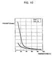
- FIG. 10 is a graph representing viscosity properties depending upon temperature between a material G perform gelatinization as intended by the present general inventive concept and ink I that is generally used in an inkjet printer head;
- FIG. 11 is a view illustrating an inkjet head in accordance with another embodiment of the present general inventive concept.
- FIG. 12 is a partial cross-sectional view taken along the line II-II′ shown in FIG. 5 , illustrating an initial filling process of the ink into the fluid channel of the head through gel ejection.
- FIG. 5 is a view illustrating a configuration of an inkjet cartridge in accordance with an embodiment of the present general inventive concept.
- a line head module 200 which is capable of printing almost simultaneously throughout an entire width of a recording medium, is detachably inserted into an inkjet cartridge 201 .
- the inkjet cartridge 201 is partitioned into spaces to receive the ink of four colors consisting of cyan, magenta, yellow and black, and is provided with a line head module mounting groove 201 a on its bottom surface, to insert the line head module 200 and fix it.
- the line head module 200 has a head frame 210 having a size to be inserted into the line head module mounting groove 201 a , and a plurality of unit heads 220 arranged in the head frame 210 .
- FIG. 6 is a partially enlarged view illustrating the line head module 200 disassembled.
- the head frame 210 is provided with a liquid supply hole 211 (hereinafter, liquid is referred to as “ink”), and a step 212 to mount the head 220 .
- liquid hereinafter, liquid is referred to as “ink”
- the head 220 includes a substrate 221 , a fluid channel forming layer 223 , a nozzle plate 225 and a heat-generating body 227 .
- FIG. 7 is a plan view partially taken from the fluid channel-forming layer 223 with the nozzle plate removed from FIG. 6 ;
- FIG. 8 is a cross-sectional view taken along the line I-I′ shown in FIG. 7 ; and
- FIG. 9 is an enlarged view partially taken of the head 200 in accordance with an embodiment of the present general inventive concept.
- the head 220 shown in FIGS. 7 , 8 and 9 is an example of the line head module type, with a gel being filled in the head before the head 220 is mounted on the inkjet cartridge 201 .
- the substrate 221 has an ink supply hole 221 a corresponding to the ink supply hole 211 of the head frame 210 at its center portion.
- the substrate 221 is provided with a fluid channel forming layer 223 to form a fluid channel 224 on its upper side.
- the fluid channel 224 includes an ink via-hole 223 a in fluid communication with the ink supply hole 221 a , a plurality of chambers 223 b , and a restrictor 223 c to connect the ink via-hole 223 a and the chambers 223 b.
- the chamber 223 b is provided with a heat-generating body 227 to generate heat to provide an ink ejecting force.
- a heat-generating body 227 is illustrated to be formed on the substrate 221 , the heat-generating body 227 can be formed on a nozzle plate 225 described hereinafter.
- the nozzle plate 225 is installed on an upper side of the fluid channel forming layer 223 and has a nozzle hole 225 a to eject the liquid droplets, generated by the heating operation of the heat-generating body 227 , at a position corresponding to the chamber 223 b.
- the filler 230 is filled into the ink supply hole 211 of the head frame 210 , the ink supply hole 221 a of the substrate 221 , and the fluid channel 224 of the fluid channel forming layer 223 , thereby preventing air from being introduced therein.
- the filler 230 may be a gel, having a high viscosity at a low temperature and a low viscosity at a high temperature (hereinafter, the filler 230 is referred to as “gel”).
- the gel designates a phase in which several or tens of sub-units are aggregated, and the aggregation is accelerated to be changed into a network structure when predetermined conditions are satisfied in the state that the sub-units (particles, high molecular substances, and colloids) are being dispersed in a solvent (generally, such a state is referred to as “sol”). In this process, the aggregation of the sub-units is progressed in an unstable state to form a cluster, thereby resulting in gelatinization.
- a bonding force aggregated to each other may generate a chemical bond or a physical bond, or both bonds simultaneously. That is, the gel with a high viscosity in a low temperature is transitioned to sol with a low viscosity in a high temperature. Depending upon a type of gel, the sol-gel transition temperatures are different. In addition, the viscosity of the gel is rapidly varied around the transition temperature.
- FIG. 10 is a graph representing viscosity properties depending upon temperature between a material G that performs gelatinization as intended by the present general inventive concept and an ink I that is generally used in an inkjet printer head.
- the gelatinization of the gel 230 is generated at a specific temperature to rapidly raise the viscosity.
- the gel 230 used in the present general inventive concept is one selected from a group consisting of phthalic acid, glycerol, unsaturated polyester, eatable collagen or agar.
- the agar is typically a hydrocolloid having a solgel transition property around a room temperature.
- the agar has a liquefaction temperature (that is, gel-sol transition) of about 50° C. in raising the temperature and a gelatinized temperature of about 35° C., and generates the phase transition reversibly by a factor of temperature only.
- the gel 230 adopted in the present general inventive concept may use a gel with a sol-gel transition temperature of about 0 to 100° C., and preferably about 5 to 60° C.
- the gel 230 preferably has a viscosity of sol of about 10 to 70 centipoises.
- FIG. 11 is a view illustrating an inkjet head in accordance with another embodiment of the present general inventive concept.
- the same named components as described hereinabove will be represented by the same reference numbers, and so their descriptions will be omitted.
- an auxiliary heat-generating body 250 is additionally installed on the substrate 221 .
- the auxiliary heat-generating body 250 functions to preheat the gel 230 to be transitioned into a liquid phase, thereby more rapidly ejecting the gel 230 through the nozzle hole 225 a .
- the heat-generating body 227 may also preheat the gel 230 to be transitioned into the liquid phase. At this time, the current applied to the heat-generating body 227 should become lower than the pulse current to perform the actual ejection.
- the head 220 as configured above, can be fabricated by the following method.
- a basic structure of the head 220 such as the substrate 221 , the fluid channel forming layer 223 , the nozzle plate 225 and the heat-generating body 227 , can be fabricated by various known methods, and their descriptions will therefore be omitted.
- the gel an essential element of the present general inventive concept, is injected into the fluid channel 224 of the fluid channel forming layer 223 .
- the gel 230 is first heated to a predetermined temperature to be transitioned into the liquid phase, and then injected into the fluid channel.
- the line head module 200 to be replaced, is inserted into the line head module mounting groove 201 a.
- FIG. 12 is a partial cross-sectional view taken along the line II-II′ shown in FIG. 5 , illustrating a process of initially filling the ink into the fluid channel 224 of the head 200 through gel ejection.
- an inkjet cartridge 201 includes a foam 203 to store the ink, an ink supply unit 205 to supply the ink from the foam 203 to the head 200 , and a filter 207 to filter the ink when the ink is ejected from the ink supply unit 205 .
- the heat-generating body 227 When the pulse current is applied to the heat-generating body 227 through current applying means after the line head module 200 is mounted on the inkjet cartridge 201 configured as above, the heat-generating body 227 generates heat.
- the gel 230 filled in the chamber 223 b is heated to become a sol, and is continuously heated to generate bubbles 231 .
- the generated bubbles 231 are continuously expanded to thereby apply pressure to the liquid-phased gel 230 filled in the chamber 223 b to eject the gel outside through the nozzle hole 225 a .
- the bubbles are shrunk, the liquid-phased gel 230 is drawn back and refilled into the chamber 223 b .
- shrinkage of the bubbles is caused by cooling of the heat-generating body 227 due to switching-off of the pulse current.
- the ink stored in the foam 203 is gradually introduced into the chamber 223 b through the ink supply unit 205 via the ink via-hole 223 a and the restrictor 223 c to fully fill the fluid channel 224 .
- the auxiliary heat-generating body 250 is heated, or low current is applied to the heat-generating body 227 . Thereby, the gel is changed into the sol, and then the ejecting operation may be performed.
- the present general inventive concept has an advantage in that it is capable of initially filling the ink into the fluid channel in the head when the head is replaced, without using an individual suction apparatus.
- the present general inventive concept has an advantage in that it is capable of decreasing loss of the ink by making the suction operation unnecessary.
- the present general inventive concept has an advantage in that it is capable of improving printing quality by decreasing a possibility of air existing in the fluid channel in the head.
Landscapes
- Engineering & Computer Science (AREA)
- Manufacturing & Machinery (AREA)
- Particle Formation And Scattering Control In Inkjet Printers (AREA)
- Ink Jet (AREA)
- Coating Apparatus (AREA)
Applications Claiming Priority (2)
| Application Number | Priority Date | Filing Date | Title |
|---|---|---|---|
| KR1020040045156A KR100612320B1 (ko) | 2004-06-17 | 2004-06-17 | 잉크젯 헤드 및 그 제조방법, 그를 이용한 헤드 교체 방법 |
| KR2004-45156 | 2004-06-17 |
Publications (2)
| Publication Number | Publication Date |
|---|---|
| US20050280666A1 US20050280666A1 (en) | 2005-12-22 |
| US7322668B2 true US7322668B2 (en) | 2008-01-29 |
Family
ID=35480117
Family Applications (1)
| Application Number | Title | Priority Date | Filing Date |
|---|---|---|---|
| US11/004,801 Expired - Fee Related US7322668B2 (en) | 2004-06-17 | 2004-12-07 | Inkjet head and methods of fabricating and exchanging the same |
Country Status (3)
| Country | Link |
|---|---|
| US (1) | US7322668B2 (ko) |
| KR (1) | KR100612320B1 (ko) |
| CN (1) | CN100457459C (ko) |
Cited By (1)
| Publication number | Priority date | Publication date | Assignee | Title |
|---|---|---|---|---|
| US20060176347A1 (en) * | 2005-02-05 | 2006-08-10 | Hong Young-Ki | Inkjet printhead assembly and ink supply apparatus for the same |
Families Citing this family (3)
| Publication number | Priority date | Publication date | Assignee | Title |
|---|---|---|---|---|
| US10495507B2 (en) | 2015-04-30 | 2019-12-03 | Hewlett-Packard Development Company, L.P. | Drop ejection based flow sensor calibration |
| CN106476270B (zh) * | 2015-08-21 | 2019-07-19 | 研能科技股份有限公司 | 喷液装置 |
| CN112924489B (zh) * | 2021-02-05 | 2022-04-12 | 西南石油大学 | 一种低温危险液体事故泄漏射流实验装置 |
Citations (16)
| Publication number | Priority date | Publication date | Assignee | Title |
|---|---|---|---|---|
| US4148041A (en) * | 1977-02-04 | 1979-04-03 | Siemens Aktiengesellschaft | Method and apparatus for purging air from jet ink writing systems |
| US5493319A (en) * | 1991-02-12 | 1996-02-20 | Canon Kabushiki Kaisha | Method of restoring ink ejection by heating an jet head before cleaning |
| JPH09169111A (ja) | 1995-12-20 | 1997-06-30 | Brother Ind Ltd | インクジェットプリンタ |
| US5840883A (en) * | 1995-04-05 | 1998-11-24 | Chiba Flour Milling Co., Ltd. | Dextrin ester of fatty acids and use thereof |
| JP2000037888A (ja) | 1998-07-21 | 2000-02-08 | Konica Corp | インクジェットプリンタ |
| US6074037A (en) * | 1996-11-15 | 2000-06-13 | Brother Kogyo Kabushiki Kaisha | Print head capping device |
| JP2001301119A (ja) | 2000-04-25 | 2001-10-30 | Riso Kagaku Corp | 印刷装置 |
| JP2002096462A (ja) | 2000-07-21 | 2002-04-02 | Fuji Photo Film Co Ltd | 記録ヘッド |
| JP2002240308A (ja) | 2001-02-20 | 2002-08-28 | Brother Ind Ltd | 記録ヘッドユニット及びインクジェット記録装置 |
| CN1408552A (zh) | 2001-09-29 | 2003-04-09 | 飞赫科技股份有限公司 | 热泡式喷墨打印头及其喷嘴板的反向显影法 |
| US6637855B2 (en) * | 2000-11-30 | 2003-10-28 | Canon Kabushiki Kaisha | Liquid discharge apparatus and discharge recovery method therefor |
| US6783205B2 (en) * | 2001-01-22 | 2004-08-31 | Canon Kabushiki Kaisha | Ink jet recording apparatus and handling method thereof |
| US6811243B2 (en) * | 2001-10-05 | 2004-11-02 | E. I. Du Pont De Nemours And Company | Priming fluid for ink jet printheads |
| US6871934B2 (en) * | 2002-03-28 | 2005-03-29 | Canon Kabushiki Kaisha | Ink jet print head and ink jet printing apparatus |
| US7188926B2 (en) * | 2002-06-13 | 2007-03-13 | Matsushita Electric Industrial Co., Ltd. | Filler solution for inkjet head, inkjet head, and recording apparatus |
| US7198351B2 (en) * | 2002-09-24 | 2007-04-03 | Brother Kogyo Kabushiki Kaisha | Ink jet recording apparatus |
Family Cites Families (4)
| Publication number | Priority date | Publication date | Assignee | Title |
|---|---|---|---|---|
| JPH0767813B2 (ja) * | 1990-07-02 | 1995-07-26 | 富士通株式会社 | 圧電素子型印字ヘッド |
| JPH0752401A (ja) * | 1993-08-20 | 1995-02-28 | Canon Inc | インクジェット記録ヘッドの保管方法 |
| JPH1134339A (ja) | 1997-07-14 | 1999-02-09 | Canon Inc | 液体噴射記録ヘッド及びその製造方法 |
| JP2001310466A (ja) * | 2000-04-28 | 2001-11-06 | Kyocera Corp | インクジェットヘッド |
-
2004
- 2004-06-17 KR KR1020040045156A patent/KR100612320B1/ko not_active IP Right Cessation
- 2004-12-07 US US11/004,801 patent/US7322668B2/en not_active Expired - Fee Related
-
2005
- 2005-04-21 CN CNB2005100674433A patent/CN100457459C/zh not_active Expired - Fee Related
Patent Citations (16)
| Publication number | Priority date | Publication date | Assignee | Title |
|---|---|---|---|---|
| US4148041A (en) * | 1977-02-04 | 1979-04-03 | Siemens Aktiengesellschaft | Method and apparatus for purging air from jet ink writing systems |
| US5493319A (en) * | 1991-02-12 | 1996-02-20 | Canon Kabushiki Kaisha | Method of restoring ink ejection by heating an jet head before cleaning |
| US5840883A (en) * | 1995-04-05 | 1998-11-24 | Chiba Flour Milling Co., Ltd. | Dextrin ester of fatty acids and use thereof |
| JPH09169111A (ja) | 1995-12-20 | 1997-06-30 | Brother Ind Ltd | インクジェットプリンタ |
| US6074037A (en) * | 1996-11-15 | 2000-06-13 | Brother Kogyo Kabushiki Kaisha | Print head capping device |
| JP2000037888A (ja) | 1998-07-21 | 2000-02-08 | Konica Corp | インクジェットプリンタ |
| JP2001301119A (ja) | 2000-04-25 | 2001-10-30 | Riso Kagaku Corp | 印刷装置 |
| JP2002096462A (ja) | 2000-07-21 | 2002-04-02 | Fuji Photo Film Co Ltd | 記録ヘッド |
| US6637855B2 (en) * | 2000-11-30 | 2003-10-28 | Canon Kabushiki Kaisha | Liquid discharge apparatus and discharge recovery method therefor |
| US6783205B2 (en) * | 2001-01-22 | 2004-08-31 | Canon Kabushiki Kaisha | Ink jet recording apparatus and handling method thereof |
| JP2002240308A (ja) | 2001-02-20 | 2002-08-28 | Brother Ind Ltd | 記録ヘッドユニット及びインクジェット記録装置 |
| CN1408552A (zh) | 2001-09-29 | 2003-04-09 | 飞赫科技股份有限公司 | 热泡式喷墨打印头及其喷嘴板的反向显影法 |
| US6811243B2 (en) * | 2001-10-05 | 2004-11-02 | E. I. Du Pont De Nemours And Company | Priming fluid for ink jet printheads |
| US6871934B2 (en) * | 2002-03-28 | 2005-03-29 | Canon Kabushiki Kaisha | Ink jet print head and ink jet printing apparatus |
| US7188926B2 (en) * | 2002-06-13 | 2007-03-13 | Matsushita Electric Industrial Co., Ltd. | Filler solution for inkjet head, inkjet head, and recording apparatus |
| US7198351B2 (en) * | 2002-09-24 | 2007-04-03 | Brother Kogyo Kabushiki Kaisha | Ink jet recording apparatus |
Non-Patent Citations (1)
| Title |
|---|
| Chinese Office Action dated Mar. 23, 2007 issued in CN 200510067443.3. |
Cited By (2)
| Publication number | Priority date | Publication date | Assignee | Title |
|---|---|---|---|---|
| US20060176347A1 (en) * | 2005-02-05 | 2006-08-10 | Hong Young-Ki | Inkjet printhead assembly and ink supply apparatus for the same |
| US7448736B2 (en) * | 2005-02-05 | 2008-11-11 | Samsung Electronics Co., Ltd. | Inkjet printhead assembly and ink supply apparatus for the same |
Also Published As
| Publication number | Publication date |
|---|---|
| CN100457459C (zh) | 2009-02-04 |
| US20050280666A1 (en) | 2005-12-22 |
| KR100612320B1 (ko) | 2006-08-16 |
| CN1709698A (zh) | 2005-12-21 |
| KR20050119990A (ko) | 2005-12-22 |
Similar Documents
| Publication | Publication Date | Title |
|---|---|---|
| JP4272837B2 (ja) | 圧力調整室およびこれを有するインクジェット記録ヘッド、これを用いたインクジェット記録装置 | |
| JP3715696B2 (ja) | 液体吐出ヘッド、ヘッドカートリッジおよび液体吐出装置 | |
| JP3153584B2 (ja) | プリントヘッドアセンブリ及びプリントヘッド加熱防止方法 | |
| JPH05131642A (ja) | インク容器、これを用いた記録ヘツドユニツトおよびこれを搭載する記録装置 | |
| JPH07164640A (ja) | インクジェット記録装置 | |
| JP2015085677A (ja) | 液体吐出ヘッド | |
| KR100406939B1 (ko) | 잉크젯 프린터 헤드 | |
| KR20010045299A (ko) | 잉크역류 방지용 네크부를 구비한 열압축방식의잉크분사장치 | |
| US6293660B1 (en) | Liquid container for ink jet head | |
| US7322668B2 (en) | Inkjet head and methods of fabricating and exchanging the same | |
| KR20010045298A (ko) | 잉크를 이용한 열압축방식의 유체분사장치 | |
| CA2108304C (en) | Ink jet recording apparatus | |
| JP2005131829A (ja) | 液体吐出性能維持方法及び液体吐出装置 | |
| KR100283755B1 (ko) | 어레이 타입 마이크로 인젝팅 디바이스 | |
| JP3263248B2 (ja) | プリント装置およびプリント方法 | |
| JP2011178041A (ja) | 制御装置及び液体噴射装置 | |
| AU744996B2 (en) | Liquid container for ink jet head | |
| JPH03101964A (ja) | インクジェットヘッド、インクジェットユニット、インクジェットカートリッジ及びインクジェット装置 | |
| JP3255526B2 (ja) | インクタンク、インク記録ヘッドカートリッジおよび装置 | |
| JPH0839800A (ja) | インクジェットプリントヘッドおよびプリント装置ならびにプリント方法 | |
| JP3229465B2 (ja) | インクジェットヘッドおよび記録装置 | |
| JP2791250B2 (ja) | インクカートリッジ | |
| KR100327255B1 (ko) | 잉크젯 프린트헤드 | |
| TWI259147B (en) | Method for preventing air from pressing into a print nozzle of an ink container by an anti-pressure | |
| JPH06183018A (ja) | インク貯蔵タンク、該インク貯蔵タンクを備えたインクジェットヘッドカートリッジおよび該インクジェットヘッドカートリッジを備えたインクジェット記録装置 |
Legal Events
| Date | Code | Title | Description |
|---|---|---|---|
| AS | Assignment |
Owner name: SAMSUNG ELECTRONICS CO., LTD., KOREA, REPUBLIC OF Free format text: ASSIGNMENT OF ASSIGNORS INTEREST;ASSIGNOR:KIM, TAE-KYUN;REEL/FRAME:016123/0931 Effective date: 20041201 |
|
| FEPP | Fee payment procedure |
Free format text: PAYOR NUMBER ASSIGNED (ORIGINAL EVENT CODE: ASPN); ENTITY STATUS OF PATENT OWNER: LARGE ENTITY |
|
| FEPP | Fee payment procedure |
Free format text: PAYOR NUMBER ASSIGNED (ORIGINAL EVENT CODE: ASPN); ENTITY STATUS OF PATENT OWNER: LARGE ENTITY Free format text: PAYER NUMBER DE-ASSIGNED (ORIGINAL EVENT CODE: RMPN); ENTITY STATUS OF PATENT OWNER: LARGE ENTITY |
|
| FPAY | Fee payment |
Year of fee payment: 4 |
|
| REMI | Maintenance fee reminder mailed | ||
| LAPS | Lapse for failure to pay maintenance fees | ||
| STCH | Information on status: patent discontinuation |
Free format text: PATENT EXPIRED DUE TO NONPAYMENT OF MAINTENANCE FEES UNDER 37 CFR 1.362 |
|
| FP | Lapsed due to failure to pay maintenance fee |
Effective date: 20160129 |
|
| AS | Assignment |
Owner name: S-PRINTING SOLUTION CO., LTD., KOREA, REPUBLIC OF Free format text: ASSIGNMENT OF ASSIGNORS INTEREST;ASSIGNOR:SAMSUNG ELECTRONICS CO., LTD;REEL/FRAME:041852/0125 Effective date: 20161104 |