US7320566B2 - Cutting tool including detachable cutter head - Google Patents
Cutting tool including detachable cutter head Download PDFInfo
- Publication number
- US7320566B2 US7320566B2 US11/342,482 US34248206A US7320566B2 US 7320566 B2 US7320566 B2 US 7320566B2 US 34248206 A US34248206 A US 34248206A US 7320566 B2 US7320566 B2 US 7320566B2
- Authority
- US
- United States
- Prior art keywords
- cutter head
- holder
- cutting tool
- protrusion
- pin
- Prior art date
- Legal status (The legal status is an assumption and is not a legal conclusion. Google has not performed a legal analysis and makes no representation as to the accuracy of the status listed.)
- Expired - Fee Related, expires
Links
Images


Classifications
-
- B—PERFORMING OPERATIONS; TRANSPORTING
- B23—MACHINE TOOLS; METAL-WORKING NOT OTHERWISE PROVIDED FOR
- B23B—TURNING; BORING
- B23B31/00—Chucks; Expansion mandrels; Adaptations thereof for remote control
- B23B31/02—Chucks
- B23B31/10—Chucks characterised by the retaining or gripping devices or their immediate operating means
- B23B31/113—Retention by bayonet connection
-
- B—PERFORMING OPERATIONS; TRANSPORTING
- B23—MACHINE TOOLS; METAL-WORKING NOT OTHERWISE PROVIDED FOR
- B23B—TURNING; BORING
- B23B29/00—Holders for non-rotary cutting tools; Boring bars or boring heads; Accessories for tool holders
- B23B29/02—Boring bars
-
- B—PERFORMING OPERATIONS; TRANSPORTING
- B23—MACHINE TOOLS; METAL-WORKING NOT OTHERWISE PROVIDED FOR
- B23B—TURNING; BORING
- B23B51/00—Tools for drilling machines
-
- B—PERFORMING OPERATIONS; TRANSPORTING
- B23—MACHINE TOOLS; METAL-WORKING NOT OTHERWISE PROVIDED FOR
- B23C—MILLING
- B23C5/00—Milling-cutters
- B23C5/02—Milling-cutters characterised by the shape of the cutter
- B23C5/06—Face-milling cutters, i.e. having only or primarily a substantially flat cutting surface
-
- B—PERFORMING OPERATIONS; TRANSPORTING
- B23—MACHINE TOOLS; METAL-WORKING NOT OTHERWISE PROVIDED FOR
- B23C—MILLING
- B23C5/00—Milling-cutters
- B23C5/02—Milling-cutters characterised by the shape of the cutter
- B23C5/10—Shank-type cutters, i.e. with an integral shaft
-
- B—PERFORMING OPERATIONS; TRANSPORTING
- B23—MACHINE TOOLS; METAL-WORKING NOT OTHERWISE PROVIDED FOR
- B23D—PLANING; SLOTTING; SHEARING; BROACHING; SAWING; FILING; SCRAPING; LIKE OPERATIONS FOR WORKING METAL BY REMOVING MATERIAL, NOT OTHERWISE PROVIDED FOR
- B23D77/00—Reaming tools
-
- B—PERFORMING OPERATIONS; TRANSPORTING
- B23—MACHINE TOOLS; METAL-WORKING NOT OTHERWISE PROVIDED FOR
- B23G—THREAD CUTTING; WORKING OF SCREWS, BOLT HEADS, OR NUTS, IN CONJUNCTION THEREWITH
- B23G5/00—Thread-cutting tools; Die-heads
-
- B—PERFORMING OPERATIONS; TRANSPORTING
- B23—MACHINE TOOLS; METAL-WORKING NOT OTHERWISE PROVIDED FOR
- B23G—THREAD CUTTING; WORKING OF SCREWS, BOLT HEADS, OR NUTS, IN CONJUNCTION THEREWITH
- B23G7/00—Forming thread by means of tools similar both in form and in manner of use to thread-cutting tools, but without removing any material
- B23G7/02—Tools for this purpose
-
- B—PERFORMING OPERATIONS; TRANSPORTING
- B23—MACHINE TOOLS; METAL-WORKING NOT OTHERWISE PROVIDED FOR
- B23B—TURNING; BORING
- B23B2222/00—Materials of tools or workpieces composed of metals, alloys or metal matrices
- B23B2222/16—Cermet
-
- B—PERFORMING OPERATIONS; TRANSPORTING
- B23—MACHINE TOOLS; METAL-WORKING NOT OTHERWISE PROVIDED FOR
- B23B—TURNING; BORING
- B23B2222/00—Materials of tools or workpieces composed of metals, alloys or metal matrices
- B23B2222/28—Details of hard metal, i.e. cemented carbide
-
- B—PERFORMING OPERATIONS; TRANSPORTING
- B23—MACHINE TOOLS; METAL-WORKING NOT OTHERWISE PROVIDED FOR
- B23B—TURNING; BORING
- B23B2222/00—Materials of tools or workpieces composed of metals, alloys or metal matrices
- B23B2222/32—Details of high speed steel
-
- B—PERFORMING OPERATIONS; TRANSPORTING
- B23—MACHINE TOOLS; METAL-WORKING NOT OTHERWISE PROVIDED FOR
- B23B—TURNING; BORING
- B23B2251/00—Details of tools for drilling machines
- B23B2251/02—Connections between shanks and removable cutting heads
-
- B—PERFORMING OPERATIONS; TRANSPORTING
- B23—MACHINE TOOLS; METAL-WORKING NOT OTHERWISE PROVIDED FOR
- B23C—MILLING
- B23C2210/00—Details of milling cutters
- B23C2210/03—Cutting heads comprised of different material than the shank irrespective of whether the head is detachable from the shank
-
- B—PERFORMING OPERATIONS; TRANSPORTING
- B23—MACHINE TOOLS; METAL-WORKING NOT OTHERWISE PROVIDED FOR
- B23C—MILLING
- B23C2222/00—Materials of tools or workpieces composed of metals, alloys or metal matrices
- B23C2222/16—Cermet
-
- B—PERFORMING OPERATIONS; TRANSPORTING
- B23—MACHINE TOOLS; METAL-WORKING NOT OTHERWISE PROVIDED FOR
- B23C—MILLING
- B23C2222/00—Materials of tools or workpieces composed of metals, alloys or metal matrices
- B23C2222/28—Details of hard metal, i.e. cemented carbide
-
- B—PERFORMING OPERATIONS; TRANSPORTING
- B23—MACHINE TOOLS; METAL-WORKING NOT OTHERWISE PROVIDED FOR
- B23C—MILLING
- B23C2222/00—Materials of tools or workpieces composed of metals, alloys or metal matrices
- B23C2222/32—Details of high speed steel
-
- Y—GENERAL TAGGING OF NEW TECHNOLOGICAL DEVELOPMENTS; GENERAL TAGGING OF CROSS-SECTIONAL TECHNOLOGIES SPANNING OVER SEVERAL SECTIONS OF THE IPC; TECHNICAL SUBJECTS COVERED BY FORMER USPC CROSS-REFERENCE ART COLLECTIONS [XRACs] AND DIGESTS
- Y10—TECHNICAL SUBJECTS COVERED BY FORMER USPC
- Y10S—TECHNICAL SUBJECTS COVERED BY FORMER USPC CROSS-REFERENCE ART COLLECTIONS [XRACs] AND DIGESTS
- Y10S408/00—Cutting by use of rotating axially moving tool
- Y10S408/713—Tool having detachable cutting edge
-
- Y—GENERAL TAGGING OF NEW TECHNOLOGICAL DEVELOPMENTS; GENERAL TAGGING OF CROSS-SECTIONAL TECHNOLOGIES SPANNING OVER SEVERAL SECTIONS OF THE IPC; TECHNICAL SUBJECTS COVERED BY FORMER USPC CROSS-REFERENCE ART COLLECTIONS [XRACs] AND DIGESTS
- Y10—TECHNICAL SUBJECTS COVERED BY FORMER USPC
- Y10T—TECHNICAL SUBJECTS COVERED BY FORMER US CLASSIFICATION
- Y10T408/00—Cutting by use of rotating axially moving tool
- Y10T408/89—Tool or Tool with support
- Y10T408/907—Tool or Tool with support including detailed shank
-
- Y—GENERAL TAGGING OF NEW TECHNOLOGICAL DEVELOPMENTS; GENERAL TAGGING OF CROSS-SECTIONAL TECHNOLOGIES SPANNING OVER SEVERAL SECTIONS OF THE IPC; TECHNICAL SUBJECTS COVERED BY FORMER USPC CROSS-REFERENCE ART COLLECTIONS [XRACs] AND DIGESTS
- Y10—TECHNICAL SUBJECTS COVERED BY FORMER USPC
- Y10T—TECHNICAL SUBJECTS COVERED BY FORMER US CLASSIFICATION
- Y10T408/00—Cutting by use of rotating axially moving tool
- Y10T408/89—Tool or Tool with support
- Y10T408/909—Having peripherally spaced cutting edges
- Y10T408/9098—Having peripherally spaced cutting edges with means to retain Tool to support
Definitions
- the present invention relates in general to a cutting tool, and more particularly to such a cutting tool including a cutter head and a holder that are detachably attached to each other.
- a cutting tool including a cutter head as the main body and a holder to which the cutter head is detachably attached.
- the cutter head is formed of cemented carbide while the holder is formed of other material, so that the increase in the product cost of the entirety of the cutting tool can be restrained.
- the cutter head is attached to the holder as described below.
- JP-H07-171702A discloses a cutting tool in which a cutting insert as the cutter head is fixed to the holder. Specifically described, the cutting insert is fitted at its supported portion in a recess that is formed in a distal end portion of the holder, and a screw fastener is provided to pass through a through-hole formed through the supported portion of the cutting insert and be tightly screwed into an internally threaded hole formed in a bottom of the recess of the distal end portion of the holder. That is, the cutting insert can be firmly fixed to the distal end portion of the holder owing to thread engagement established by the screw fastener. In this arrangement in which the cutting insert is detachably attached to the holder only by the thread engagement, the cutting insert can be easily replaced with a new one, for example, when the cutting insert is worn out.
- JP-2002-103130A discloses a cutting tool in which the cutter head is attached to the holder by thread engagement.
- the cutter head has a protrusion formed in its axial end portion, while the holder has a recess formed in its axial end portion.
- the protrusion of the cutter head has an external thread formed in its outer surface, and the recess has an internal thread formed in its inner surface, so that the cutter head is tightly screwed into the holder. That is, the cutter head can be firmly fixed at its protrusion in the recess of the holder owing to the thread engagement.
- the cutter head can be easily changed to a new one, as needed, without changing the holder.
- JP-2001-505136A discloses a cutting tool in which the cutter head and a shank as the holder are attached to each other through a retainer interposed therebetween.
- the cutter head and the retainer have respective hook-shaped engaging portions, so that the cutter head is held in engagement at its engaging portion with the engaging portion of the retainer that is fitted in a hole of the shank.
- the cutter head is firmly fixed relative to the shank. In this arrangement, too, the cutter head can be changed to a new one, as needed, without changing the shank.
- JP-2000-176723A discloses a cutting tool in which the cutter head is attached to a shank as the holder, by means of shrinkage fitting. Specifically described, the cutter head has an axial protrusion while the shank has a recess or hole, such that the axial protrusion of the cutter head can be fitted into the hole of the shank, with the shank being heated.
- the cutter head is firmly fixed to the shank, since the diameter of the hole of the shank is reduced when the temperature of the shank is eventually returned to an ordinary temperature causing the shank to shrink. In this arrangement, the cutter head can be replaced with a new one, as needed, by heating the shank.
- JP-2000-176723A since the shank has to be heated each time the cutter head is attached to or removed from the shank, the cutting tool requires a heating device used to heat the shank, leading to the consequent increase in installation cost.
- the present invention was made in view of the background prior art discussed above. It is therefore an object of the present invention to provide a cutting tool which includes a cutter head and a holder that are detachably attached to each other, and which has an arrangement enabling the cutter head to be firmly fixed to the holder and also leading to reduction in cost required for manufacturing the cutting tool. This object may be achieved according to any one of first through eighth aspects of the invention which are described below.
- the first aspect of this invention provides a cutting tool that is to be rotated relative to a workpiece, for performing a cutting operation, the cutting tool including: a cutter head; and a holder holding the cutter head, wherein one of the cutter head and the holder has a recess formed in an axial end portion thereof and defined by a circumferential wall thereof, wherein the other of the cutter head and the holder has a protrusion formed in an axial end portion thereof, such that the cutter head and the holder are detachably attached to each other, with the protrusion being introduced in the recess by an axial distance, wherein the one of the cutter head and the holder has a pair of coaxial holes in the form of first and second pin receiver holes which are formed in the circumferential wall and which are coaxial with each other, wherein the other of the cutter head and the holder has an engaging surface which is recessed from an outer circumferential surface of the protrusion and which is held in engagement with a pin that is received in the first and second pin receiver holes, and
- the one of the cutter head and the holder is provided by the holder, while the other of the cutter head and the holder is provided by the cutter head.
- each of the first and second pin receiver holes has a front portion and a rear portion that is located on a rear side of the front portion as viewed in a rotating direction in which the cutting tool is to be rotated in the cutting operation, wherein the rear portion is more distant than the front portion, from the other of the cutter head and the holder as viewed in an axial direction of the cutting tool.
- the first pin receiver hole is located on a rear side of the second pin receiver hole as viewed in a rotating direction in which the cutting tool is to be rotated in the cutting operation, wherein the first pin receiver hole is more distant than the second pin receiver hole, from the other of the cutter head and the holder as viewed in an axial direction of the cutting tool.
- the protrusion has a tapered outer surface that is inclined with respect to an axis of the protrusion, wherein the recess has a tapered inner surface whose taper angle corresponds to that of the tapered outer surface, so that the protrusion and the recess are fitted at the respective tapered outer and inner surfaces.
- the first and second pin receiver holes as the pair of coaxial holes are positioned relative to the circumferential wall, such that the pin received in the first and second pin receiver holes has an axially intermediate portion which is located between the first and second pin receiver holes and which is at least partially embedded in the circumferential wall.
- the protrusion in the cutting tool defined in any one of the first through sixth aspects of the invention, includes an arc-shaped flange portion which projects outwardly in a radial direction of the protrusion, wherein the engaging surface is provided by the arc-shaped flange portion, and has a radially outer end radially distant from an axis of the protrusion by a distance that is substantially half of an inside diameter of the recess.
- the one of the cutter head and the holder has, in addition to the pair of coaxial holes, at least one pair of coaxial hole, such that the plurality of pairs of coaxial holes are equally spaced apart from each other in a circumferential direction of the one of the cutter head and the holder.
- each of the first and second pin receiver holes is inclined, with respect to the plane perpendicular to the axis of the above-described one of the cutter head and the holder, in such a direction that increases the axial distance by which the protrusion is introduced in the recess, owing to a cutting resistance generated in the cutting operation, namely, in such a direction that forces the protrusion to be further introduced into the recess.
- This arrangement is effective to enable the cutter head and the holder to be firmly fixed to each other, with a sufficiently large strength with which the engaging surface is held in engagement with the pin.
- cutting resistance used in the present specification is interpreted to principally mean, unless otherwise specified, a component of the cutting resistance or force exerted by the workpiece (that is being cut by the cutting tool), which component acts on the cutting tool in a direction opposite to the rotating direction of the cutting tool relative to the workpiece.
- the cutter head and the holder are detachably attached to each other, the cutter head can be changed to a new one without changing the holder, for example, where the cutter head is worn out. By thus eliminating necessity of changing an entirety of the cutting tool, it is possible to reduce a tooling cost.
- the cutter head and the holder can be made of respective different materials, only the cutter head can be made of cemented carbide. It is therefore possible to reduce a material cost and a machining cost, as compared with a solid-type cemented carbide tool in which the cutting tool is formed in its entirety with cemented carbide.
- the pin received or fitted in the first and second pin receiving holes is subjected to a load during the cutting operation, and is replaceable with a new one when being damaged.
- This arrangement eliminates a necessity of replacing an entirety of the cutter head or the holder with a new one, leading to reduction in the material cost.
- the above-described one of the cutter head and the holder requires, as arrangement for attaching it to the above-described other of the cutter head and the holder, only the first and second pin receiver holes and the pin received or fitted in the pin receiver holes.
- the above-described one can be manufactured at a reduced cost.
- the cutter head and the holder can be held in contact with each other over a sufficiently large contact area, so as to be further firmly fixed to each other. Further, the taper fitting arrangement facilitates establishment of a coaxial relationship between the cutter head and the holder.
- the first and second pin receiver holes are positioned relative to the circumferential wall of the above-described one of the cutter head and the holder, such that the axially intermediate portion of the pin is at least partially embedded in the circumferential wall, namely, such that at least a portion of an outer circumferential surface of the pin is embedded in the circumferential wall.
- the engaging surface (held in engagement with the pin) is provided by the arc-shaped flange portion projecting outwardly in the radial direction, and the radially outer end of the engaging surface is distant from the axis by the distance that is substantially half of the inside diameter of the recess.
- FIG. 1 is an exploded view of a cutting tool constructed according to an embodiment of the invention
- FIG. 2A is a view of a cutter head of the cutting tool of FIG. 1 , as seen in a direction indicted by arrow 2 A in FIG. 1 ;
- FIG. 2B is a view of the cutter head, as seen in a direction indicated by arrow 2 B in FIG. 2A ;
- FIG. 3A is a cross sectional view of the cutter head, taken along line 3 A- 3 A in FIG. 2A ;
- FIG. 3B is a cross sectional view of the cutter head, taken along line 3 B- 3 B in FIG. 2A ;
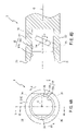
- FIG. 4A is a view of a cutter head holder of the cutting tool of FIG. 1 , as seen in a direction indicted by arrow 4 A in FIG. 1 ;
- FIG. 4B is a cross sectional view of the cutter head holder, taken along line 4 B- 4 B in FIG. 4A ;
- FIG. 5 is a cross sectional view of the cutter head holder taken along line 5 - 5 in FIG. 4A , together with the cutter head attached to the cutter head holder.
- FIG. 1 is an exploded view of the cutting tool 1 including a cutter head 2 and a cutter head holder 3 .
- one of axially opposite end portions of the cutter head holder 3 (a left end portion of the cutter head holder 3 as seen in FIG. 1 ) is shown in its cross section, and an axially intermediate portion of the cutter head holder 3 is not illustrated.
- the cutting tool 1 is attached to a spindle of a machine tool (such as a milling or drilling machine with or without a numerical control system), through a suitable tool holder (not shown) that is attached to the spindle, so that a rotary motion of the spindle is transmitted to the cutting tool 1 via the tool holder, whereby a cutting operation is performed by the cutting tool 1 .
- a machine tool such as a milling or drilling machine with or without a numerical control system
- the cutter head 2 and the cutter head holder 3 are detachably attached to each other, so that the two elements 2 , 3 can be formed of respective different materials.
- the holder 3 may be formed of other material such as high-speed tool steel, thereby making possible to reduce a material cost and a machining cost.
- the cutter head 2 can be changed to a new one without changing the holder 3 , for example, where the cutter head 2 is worn.
- the cutter head 2 includes a main portion in the form of a cutting blade portion 23 that is caused to cut a workpiece in the cutting operation, and an attached portion in the form of an axial protrusion 22 that is formed in an axially proximal end portion of the cutter head 2 .
- the protrusion 22 axially protrudes from a rear end surface 21 of the cutting blade portion 23 (from a right end surface of the blade portion 23 as seen in FIG. 1 ), which surface is perpendicular to an axis of the cutter head 2 .
- the cutting blade portion 23 has: at least one flute formed in its outer circumferential surface and extending from its axially distal end toward its axially proximal end; at least one cutting edge each defined by an edge of a corresponding one of the at least one chip evacuation flute; and at least one flank surface each located on a rear side of a corresponding one of the at least one cutting edge as viewed in a rotating direction of the cutting tool 1 , although the flute, cutting edge and flank surface are not illustrated in the accompanying drawings in which the cutting blade portion 23 is schematically presented. It is noted that, while the cutter head 2 is provided by a drill, the cutter head 2 may be provided by other type of cutter such as end mill, face mill, reamer, boring bar, thread-milling cutter and thread-forming tap.
- the protrusion 22 of the cutter head 2 is fittable into an axial hole or recess 32 that is formed in an axially distal end portion (front end portion) of the cutter head holder 3 .
- the protrusion 22 has a tapered outer surface 22 a that is axially contiguous to the rear end surface 21 , a straight or non-tapered outer surface 22 b that is axially contiguous to the tapered outer surface 22 a , and an engaging surface 22 c that extends from the non-tapered outer surface 22 b outwardly in a radial direction of the protrusion 22 (in a vertical direction as seen in FIG. 1 ).
- the tapered outer surface 22 a is provided by a tapered portion of the protrusion 22 having an outside diameter gradually reduced as viewed in a direction toward a rear end portion of the protrusion 22 (as viewed in a rightward direction as seen in FIG. 1 ).
- the non-tapered outer surface 22 b is provided by a non-tapered portion of the protrusion 22 having an outside diameter that is smaller than the outside diameter of the portion providing the tapered outer surface 22 a.
- the tapered outer surface 22 a has a taper angle (taper ratio) corresponding to that of a tapered inner surface 32 b of the recess 32 of the cutter head holder 3 . It is noted that the taper angle of the tapered outer and inner surfaces 22 a , 32 b is not smaller than 1/20 and is not larger than 1 ⁇ 5.
- the non-tapered portion of the protrusion 22 is axially contiguous to the tapered portion of the protrusion 22 , and the outside diameter of the non-tapered portion is smaller than an inside diameter L 1 of a non-tapered portion of the recess 32 of the holder 3 .
- the protrusion 22 includes a pair of arc-shaped flange portions each projecting outwardly in its radial direction (in the vertical direction as seen in FIG. 1 ).
- the engaging surface 22 c is provided by one of axially opposite end surfaces of each of the arc-shaped flange portions which faces toward the cutting blade portion 23 (i.e., a left one of the axially opposite end surfaces of each arc-shaped flange portion as seen in FIG. 1 ). That is, the engaging surface 22 c is recessed from an outer circumferential surface of the protrusion 22 .
- the engaging surface 22 c has a radially outer end that is radially distant from an axis of the protrusion 22 by a distance R 1 . This distance R 1 (i.e., a radius R 1 of the arc-shaped flange portion) is about half of the inside diameter L 1 of the non-tapered portion of the recess 32 .
- the cutter head holder 3 has an axially distal end surface 31 , and an outer circumferential wall 33 located in its axially distal end portion.
- the above-described recess 32 is formed in the axially distal end surface 31 so as to extend by a predetermined axial distance, and is defined or surrounded by the outer circumferential wall 33 .
- the holder 3 has two pairs of coaxial holes each provided by first and second pin receiver holes 35 , 36 that are formed in the outer circumferential wall 33 .
- Two pins 34 are provided to be press-fitted in the respective two pairs of coaxial holes (see FIGS. 4A and 4B ).
- the holder 3 may be formed of other material such as cermet, CBN (cubic boron nitrides) sintered body, powder high-speed steel (sintered high-speed tool steel) and alloy tool steel.
- the holder 3 is preferably formed of a material which is softer than a material forming the cutter head 2 .
- the holder 3 is preferably formed of high-speed tool steel.
- the holder 3 is preferably formed of cermet. Owing to such a material selection, the holder 3 is given a higher degree of deformability than the cutter head 2 .
- the holder 3 is deformable upon fitting of the protrusion 22 into the recess 32 , thereby eliminating necessity of machining the holder 3 with an extremely high precision, and leading to the consequent reduction in manufacturing cost.
- the recess 32 of the holder 3 serves as an attached portion at which the holder 3 is attached to the cutter head 2 , and has the above-described tapered inner surface 32 b and a straight or non-tapered surface 32 a that is substantially parallel to an axis of the holder 3 (i.e., an axis O of the cutting tool 1 ).
- the tapered inner surface 32 b which is axially contiguous to the non-tapered surface 32 a , is provided by a tapered portion of the recess 32 having an inside diameter gradually increased as viewed in a direction toward an opening of the recess 32 (as viewed in a leftward direction as seen in FIG. 1 ).
- An axial depth L 3 of the recess 32 (i.e., an axial distance L 3 between the opening and bottom of the recess 32 ) is larger than an axial distance L 2 between the axially proximal and distal ends of the protrusion 22 .
- the inside diameter L 1 of the non-tapered portion of the recess 32 providing the non-tapered surface 32 a is about twice as large as the above-described distance R 1 by which the radially outer end of the engaging surface 22 c is radially distant from the axis of the protrusion 22 .
- the taper angle (taper ratio) of the tapered inner surface 32 b corresponds to that of the tapered outer surface 22 a , and is not smaller than 1/20 and is not larger than 1 ⁇ 5.
- the outer circumferential wall 33 defining a periphery of the recess 32 has the two pairs of coaxial holes each provided by the first and second pin receiver holes 35 , 36 .
- Each of the pins 34 is provided by a generally cylindrical member (straight pin) having an outside diameter that is substantially equal to an inside diameter of the coaxial holes (first and second receiver holes 35 , 36 ), and is press-fitted in a corresponding one of the two pairs of coaxial holes.
- Each of the pins 34 has an axially intermediate portion which is located between the first and second pin receiver holes 35 , 36 as the corresponding pair of coaxial holes and which includes a part projecting inwardly from an inner circumferential surface of the outer circumferential wall 33 (see FIG. 4A ), so that the inwardly projecting part of the axially intermediate portion of the pin 34 is held in engagement with the engaging surface 22 c of the protrusion 22 .
- the pins 34 are formed of high-speed tool steel in the present embodiment, they may be formed of other material such as cemented carbide. Where the pins 34 are formed of high-speed tool steel, the pins 34 exhibit a higher degree of deformability than where they are formed of cemented carbide, so that the pins 34 can be more easily press-fitted into the first and second pin receiver holes 35 , 36 , thereby facilitating an operation to attach the cutter head 2 to the holder 3 .
- the pins 34 are formed of cemented carbide, on the other hand, the pins 34 exhibit a higher degree of hardness than where they are formed of high-speed tool steel, so that the pins 34 are prevented from being damaged due to their engagement with the respective engaging surfaces 22 c , thereby leading to a prolonged tool life of the cutting tool 1 in its entirety.
- the pins 34 are formed of a suitable one of various materials that is selected depending upon conditions of the cutting operation, particularly, a degree of hardness of the workpiece that is to be machined in the cutting operation.
- the pins 34 are preferably formed of cemented carbide, for providing the pins 34 with a high durability even against a high cutting resistance generated in the cutting operation.
- the protrusion 22 has, in its rear end portion, a part-cylindrical portion having a pair of substantially arcuate surfaces and a pair of flat surfaces substantially that are substantially parallel to each other, as shown in FIG. 2A .
- the pair of arcuate surfaces are diametrically opposed to each other, while the pair of flat surfaces are diametrically opposed to each other, so that the arcuate surfaces and the flat surfaces are alternately arranged as viewed in a circumferential direction of the protrusion 22 .
- a distance between the pair of flat surfaces is substantially equal to the outside diameter of the non-tapered portion of the protrusion 22 that provides the non-tapered outer surface 22 b (see FIG. 3B ).
- Each of the pair of arcuate surfaces is provided by a corresponding one of the above-described pair of arc-shaped flange portions providing the engaging surface 22 c .
- the engaging surface 22 c is contiguous to the non-tapered outer surface 22 b , and is located in each of positions that are diametrically opposed to each other.
- Each of the two diametrically opposed engaging surfaces 22 c is inclined with respect to a plane perpendicular to the axis O by an angle ⁇ 1 (see FIG. 2B ).
- the cutter head 2 is provided by a drill head that is to be rotated in a clockwise direction (as seen in the direction indicated by arrow 2 A in FIG. 1 ) as a predetermined rotating direction.
- the flute and leading edge formed in the cutting blade portion 23 of the cutter head 2 are provided by right-hand flute and leading edge, although not illustrated in the accompanying drawings.
- Each of the two diametrically opposed engaging surfaces 22 c has a front portion (i.e., a right portion as seen in FIG. 2B ) and a rear portion (i.e., a left portion as seen in FIG. 2B ) that is located on a rear side of the front portion as viewed in the above-described rotating direction, such that the rear portion is more distant than the front portion, from the cutting blade portion 23 as viewed in the axial direction.
- This arrangement of the inclination of each of the engaging surfaces 22 c with respect to the above-described plane is effective to cause the tapered outer and inner surfaces 22 a , 32 b of the respective protrusion 22 and recess 32 to be forced against each other by a cutting resistance generated in the cutting operation, namely, to cause the protrusion 22 to be forced by the cutting resistance to be further introduced into the recess 32 , thereby enabling the cutter head 2 and the holder 3 to be further firmly fixed to each other, with the tapered outer and inner surfaces 22 a , 32 b being held in fitting engagement with a sufficiently large strength as well as with each of the engaging surfaces 22 c and a corresponding one of the pins 34 being held in engagement with a sufficiently large strength.
- each of the engaging surfaces 22 c is inclined with respect to the above-described plane such that the rear portion of each engaging surface 22 c is more distant than the front portion of each engaging surface 22 c , from the cutting blade portion 23 as viewed in the axial direction.
- this arrangement is effective to enable the cutter head 2 and the holder 3 to be further firmly fixed to each other, with the tapered outer and inner surfaces 22 a , 32 b being held in fitting engagement with a sufficiently large strength.
- each engaging surface 22 c is provided by the right and left portions of each engaging surface 22 c , respectively, as seen in FIG. 2B in the case of the drill head with right-hand flute
- the front and rear portions of each engaging surface 22 c would be provided by the left and right portions of each engaging surface 22 c , respectively, as seen in a figure corresponding to FIG. 2B in the case of the drill head with left-hand flute.
- the above-described angle 01 of the inclination of each engaging surface 22 c with respect to the plane perpendicular to the axis O is preferably not smaller than 5° and not larger than 45°. If the inclination angle ⁇ 1 is smaller than 5°, there might be a risk that the cutting resistance would cause the cutter head 2 to be rotated relative to the holder 3 . If the inclination angle ⁇ 1 is larger than 45°, on the other hand, a component of a force exerted by the pin 34 onto the engaging surface 22 c , which component acts in the axial direction, might be too small to sufficiently force the protrusion 22 of the cutter head 2 to be further introduced into the recess 32 of the holder 3 .
- the inclination angle ⁇ 1 being set to a value not smaller than 5° and not larger than 45°, it is possible to assure firm attachment of the cutter head 2 to the holder 3 while reliably preventing a rotation of the cutter head 2 relative to the holder 3 .
- Each of the first and second pin receiving holes 35 , 36 is provided by a substantially circular-shaped hole having an inside diameter substantially equal to the outside diameter of the pin 34 .
- the first pin receiver hole 35 is located on a rear side of the second receiver pin hole 36 as viewed in the rotating direction (indicated by arrows R in FIG. 4A ).
- the first pin receiver holes 35 of the respective two pairs of coaxial holes are positioned to be symmetrical with each other with respect to the axis O, as shown in FIG. 4A .
- the second pin receiver holes 36 of the respective two pairs of coaxial holes are positioned to be symmetrical with each other with respect to the axis O.
- each of the two pins 34 is press-fitted in a corresponding one of the pairs of coaxial holes (first and second pin receiver holes 35 , 36 ).
- the axially intermediate portion of each pin 34 located between the first and second pin receiver holes 35 , 36 includes the part projecting inwardly from the inner circumferential surface of the outer circumferential wall 33 (see FIG. 4A ), so that the inwardly projecting part of the axially intermediate portion of the pin 34 is held in engagement with the engaging surface 22 c of the protrusion 22 .
- Each pin 34 received in the first and second pin receiving holes 35 , 36 is subjected to a load in the cutting operation, and is replaceable with a new one when being damaged. This arrangement eliminates a necessity of replacing an entirety of the holder 3 with a new one, leading to reduction in the material cost.
- the first and second pin receiver holes 35 , 36 of each of the pairs of coaxial holes are positioned relative to the outer circumferential wall 33 , such that a connecting hole connecting and coaxial to the first and second pin receiver holes 35 , 36 is partially defined by the outer circumferential wall 33 , namely, such that the axially intermediate portion of the pin 34 (located in the connecting hole between the first and second pin receiver holes 35 , 36 ) is at least partially embedded in the outer circumferential wall 33 .
- This arrangement enables the pin 34 to have a required degree of strength, thereby restraining the pin 34 from being damaged due to a cutting resistance acting on the cutting tool 1 , leading to prolongation in life of the pin 34 , and minimizing risk of removal of the cutter head 2 from the holder 3 .
- the second pin receiver hole 36 is located to be closer than the first pin receiver hole 35 , to the axially distal end of the holder 3 (i.e., left end of the holder 3 as seen in FIG. 4B ) as viewed in the axial direction, as shown in FIG. 4B .
- the pin 34 fitted in the first and second receiver hole 34 is inclined such that a front portion of the pin 34 is closer than a rear portion of the pin 34 (located on a rear side of the front portion of the pin 34 ), to the axially distal end of the holder 3 as viewed in the axial direction.
- This arrangement of the inclination of the pin 34 is effective to cause the protrusion 22 to be forced by the cutting resistance to be further introduced into the recess 32 , thereby enabling the cutter head 2 and the holder 3 to be further firmly fixed to each other, with the tapered outer and inner surfaces 22 a , 32 b being held in fitting engagement with a sufficiently large strength, as well as with the pin 34 and the engaging surface 22 c being held in engagement with a sufficiently large strength.
- the second pin receiver hole 36 is located to be closer than the first pin receiver hole 35 (located on the rear side of the second receiver hole 36 as viewed in the rotating direction), to the axially distal end of the holder 3 as viewed in the axial direction.
- this arrangement is effective to enable the cutter head 2 and the holder 3 to be further firmly fixed to each other, with the tapered outer and inner surfaces 22 a , 32 b being held in fitting engagement with a sufficiently large strength.
- An angle ⁇ 2 of the inclination of the pin 34 (the first and second pin receiver holes 35 , 36 ) with respect to the plane perpendicular to the axis O is preferably substantially equal to the above-described inclination angle ⁇ 1 (see FIG. 2B ).
- This preferable arrangement is effective to maximize an area over which the pin 34 and the engaging surface 22 c are held in engagement with each other, thereby facilitating the cutter head 2 to be firmly fixed to the holder 3 .
- the number of pairs of coaxial holes (first and second pin receiver holes 35 , 36 ) is two so that the two pins 34 are received in the respective two pairs of coaxial holes.
- the number of pair or pairs of coaxial holes may be one, three or more than three. Where the number of pairs of coaxial holes is two or more, the plurality of pairs of coaxial holes are equally spaced apart from each other in the circumferential direction.
- FIG. 5 there will be described the attachment of the cutter head 2 and the cutter head holder 3 to each other. It is noted that, in FIG. 5 , the holder 3 is not shown in its entirety but is shown only in its axially distal end portion.
- the protrusion 22 of the cutter head 2 is fitted in the recess 32 of the holder 3 , with the tapered outer surface 22 a of the cutter head 2 is held in close contact with the tapered inner surface 32 b of the holder 3 .
- the cutter head 2 and the recess 32 can be held in mutual contact over a larger area, than in an arrangement in which the tapered outer and inner surfaces 22 a , 32 b are replaced with non-tapered surfaces substantially parallel to the axis O. That is, the taper fitting enables to the cutter head 2 and the holder 3 to be further firmly fixed to each other.
- the taper angle (taper ratio) of the tapered outer and inner surfaces 22 a , 32 b is not smaller than 1/20 and is not larger than 1 ⁇ 5. If the taper angle is smaller than 1/20, a component of a force exerted by each one of the tapered outer and inner surfaces 22 a , 32 b onto the other of the surfaces 22 a , 32 b , which component acts in the axial direction, is made small, making it possible to reduce a risk of removal of the protrusion 22 from the recess 32 .
- the extremely small taper angle requires an increase in the axial distance L 2 between the axially proximal and distal ends of the protrusion 22 , leading to increase in the material cost.
- the taper angle is larger than 1 ⁇ 5, on the other hand, the required axial distance L 2 of the protrusion 22 can be made small, leading to reduction in the material cost. However, the extremely large taper angle could increase a risk of removal of the protrusion 22 from the recess 32 .
- the axial distance L 3 between the opening and bottom of the recess 32 is larger than the axial distance L 2 between the axially proximal and distal ends of the protrusion 22 , as described above. This arrangement assures a spacing gap between the surfaces 21 , 31 and a spacing gap between the distal end of the protrusion 22 and the bottom of the recess 32 .
- the surfaces 21 , 31 are not brought into contact with each other, and the distal end of the protrusion 22 and the bottom of the recess 32 are not brought into contact with each other, thereby eliminating a risk of separation of the tapered outer and inner surfaces 22 a , 32 b from each other. Since the risk of the separation of the tapered outer and inner surfaces 22 a , 32 b is thus eliminated, it is possible to maintain the firm fixation of the cutter head 2 to the cutter head holder 3 .
- the radius R 1 of the arc-shaped flange portion providing each engaging surface 22 c is adapted to be about half of the inside diameter L 1 of the non-tapered portion of the recess 32 , as described above.
- This arrangement permits the arc-shaped flange portion to be held in contact at its radially outer end surface with the non-tapered inner surface 32 a (i.e., with the non-tapered portion of the recess 32 ), enabling the engaging surface 22 c to be engaged over its sufficiently large area with the pin 34 , and accordingly making it possible to further firmly attach the cutter head 2 and the holder 3 to each other.
- the cost required for the components can be reduced by eliminating provision of an additional member between the cutter head 2 and the holder 3 , which additional member has been required in a conventional cutting tool as disclosed in the above-mentioned JP-2001-505136A.
- the present cutting tool 1 does not require a heating device, which has been required in a conventional cutting tool as disclosed in the above-mentioned JP-2000-176723A, for heating the holder (shank) each time the cutter head is attached to or removed from the holder.
- a heating device which has been required in a conventional cutting tool as disclosed in the above-mentioned JP-2000-176723A, for heating the holder (shank) each time the cutter head is attached to or removed from the holder.
- the elimination of necessity of the heating device leads to reduction in the installation cost.
- each of the pins 34 is radially spaced apart from the non-tapered outer surface 22 b of the protrusion 22 , as shown in FIG. 5 .
- each of the pins 34 may have an outside diameter that is determined such that the pin 34 is held in contact with the non-tapered outer surface 22 b .
- each pin 34 is held in contact at its two surfaces with the respective engaging surface 22 c and non-tapered outer surface 22 b , thereby making is possible to further firmly attach the cutter head 2 to the holder 3 .
- each pin 34 is provided by the straight pin in the above-described embodiment, it may be provided by a tapered pin. Where each pin 34 is provided by the taper pin, the pin 34 can be further easily press-fitted and removed in and from the first and second pin receiver holes 35 , 36 , leading to an improvement in efficiency of the operation.
- each pin 34 and the first and second pin receiver holes 35 , 36 may be fixed by thread engagement, for example, by forming an external thread in the outer circumferential surface of the pin 34 while forming an internal thread in the inner circumferential surfaces of each of the holes 35 , 36 .
- This arrangement facilitates the attachment of the pin 34 into the holes 35 , 36 , leading to an improvement in efficiency of the operation.
- an internally threaded hole may be formed in an axial end surface of each pin 34 , so that the pin 34 can be easily removed from the holes 35 , 36 , by using, for example, an extractor tool in the form of an externally threaded member, which is to be screwed into the internally threaded hole of the pin 34 and then pulled together with the pin 34 .
- each pin 34 has a substantially circular shape in its cross section in the above-described embodiment, it may have a substantially elliptic shape or polygonal shape in its cross section.
- each engaging surface 22 c and each pair of coaxial holes are both inclined with respect to the plane perpendicular to the axis O.
- this arrangement may be modified such that only one of each engaging surface 22 c and each pair of coaxial holes is inclined while the other is not inclined. This modified arrangement leads to reduction in the manufacturing cost.
- the two pairs of coaxial holes are the same in that the coaxial holes are inclined such that the rear portion of each of the coaxial holes is more distant than the front portion of each of the coaxial holes (that is located on a front side of the rear portion as viewed in the clockwise direction as the predetermined rotating direction), from the cutter head 2 as viewed in the axial direction.
- the two pairs of coaxial holes may be different from each other such that the rear portion is more distant than the front portion from the cutter head 2 in one of the two pairs of coaxial holes while the rear portion is closer than the front portion to the cutter head 2 in the other of the two pairs of coaxial holes.
- This modified arrangement enables the cutter head 2 to be firmly attached to the holder 3 , irrespective of whether the cutting tool 1 is rotated in the clockwise direction or counterclockwise direction. That is, where the cutter head 2 is designed to be rotated in the clockwise direction in the cutting operation, the protrusion 22 of the cutter head 2 is forced by the cutting resistance to be further introduced into the recess 32 of the holder 3 , as a result of the engagement of a corresponding one of the engaging surfaces 22 with the a corresponding one of the pins 34 received in the above-described one of the two pairs of coaxial holes.
- the cutter head holder 3 with this modified arrangement can serve as a holder that is common to cutter heads such as drills having respective flutes that are twisted in different directions.
Applications Claiming Priority (2)
| Application Number | Priority Date | Filing Date | Title |
|---|---|---|---|
| JP2005-226742 | 2005-08-04 | ||
| JP2005226742A JP2007038362A (ja) | 2005-08-04 | 2005-08-04 | 切削工具 |
Publications (2)
| Publication Number | Publication Date |
|---|---|
| US20070031203A1 US20070031203A1 (en) | 2007-02-08 |
| US7320566B2 true US7320566B2 (en) | 2008-01-22 |
Family
ID=37681213
Family Applications (1)
| Application Number | Title | Priority Date | Filing Date |
|---|---|---|---|
| US11/342,482 Expired - Fee Related US7320566B2 (en) | 2005-08-04 | 2006-01-30 | Cutting tool including detachable cutter head |
Country Status (3)
| Country | Link |
|---|---|
| US (1) | US7320566B2 (de) |
| JP (1) | JP2007038362A (de) |
| DE (1) | DE102006014602A1 (de) |
Cited By (1)
| Publication number | Priority date | Publication date | Assignee | Title |
|---|---|---|---|---|
| US20110068545A1 (en) * | 2009-09-23 | 2011-03-24 | Esa Eppinger Gmbh | Interface between a receptacle body and an insert designed, in particular, as a tool holder of a workpiece holder |
Families Citing this family (11)
| Publication number | Priority date | Publication date | Assignee | Title |
|---|---|---|---|---|
| SE531746C2 (sv) * | 2007-07-03 | 2009-07-28 | Seco Tools Ab | I flera delar utformad verktygsenhet och skärverktyg |
| DE102009028020B4 (de) * | 2009-07-27 | 2011-07-28 | Hilti Aktiengesellschaft | Bohrer und Herstellungsverfahren |
| AT13021U1 (de) * | 2009-12-07 | 2013-04-15 | Johne & Co Praez Swerkzeuge Gmbh | Fräswerkzeug und fräskopf |
| DE102009060678B4 (de) * | 2009-12-28 | 2015-06-25 | Wto Werkzeug-Einrichtungen Gmbh | Werkzeugträger mit einer Spannzangenaufnahme und Werkzeugeinsatz zur Verwendung in einem Werkzeugträger |
| SE534648C2 (sv) * | 2010-03-26 | 2011-11-08 | Sandvik Intellectual Property | Roterbart verktyg för spånavskiljande bearbetning samt löstopp och grundkropp härför |
| DE102011116974A1 (de) * | 2011-10-26 | 2013-05-02 | Vollmer Werke Maschinenfabrik Gmbh | Vorrichtung und Verfahren zum Herstellen einer Führungsfase an einem Werkstück, insbesondere an einem schneidenden Werkzeug |
| CN102658389A (zh) * | 2012-05-04 | 2012-09-12 | 中国航天科技集团公司烽火机械厂 | 一种侧壁内锥孔的成型装置 |
| DE102013213123C5 (de) | 2013-07-04 | 2022-08-11 | Schwegler Werkzeugfabrik Gmbh & Co. Kg | Wechselkopfsystem für die Metallbearbeitung |
| DE102018100476A1 (de) * | 2018-01-10 | 2019-07-11 | Gühring KG | Vorrichtung zum spannen eines schaftwerkzeugs in einer werkzeugaufnahme |
| JP7357892B2 (ja) * | 2018-12-27 | 2023-10-10 | 三星ダイヤモンド工業株式会社 | ホルダジョイント、ホルダユニット、およびスクライブ装置 |
| TWI679080B (zh) * | 2019-02-27 | 2019-12-11 | 張新添 | 刀把結構 |
Citations (16)
| Publication number | Priority date | Publication date | Assignee | Title |
|---|---|---|---|---|
| US748890A (en) * | 1904-01-05 | Metal-boring tool | ||
| US1413280A (en) * | 1921-04-28 | 1922-04-18 | Eclipse Interchangeable Counte | Locking device for boring or other tools |
| US2158120A (en) * | 1936-02-19 | 1939-05-16 | Charles A Hirschberg | Detachable drill bit |
| US3304816A (en) * | 1965-04-07 | 1967-02-21 | Louis C Galorneau | Detachable drill tip and coupling means |
| JPH0197512A (ja) * | 1987-10-06 | 1989-04-17 | Hiroyuki Nakayama | 穿孔工具 |
| SU1696174A1 (ru) * | 1989-08-02 | 1991-12-07 | Магнитогорский металлургический комбинат им.В.И.Ленина | Однокромочное сверло дл глубокого сверлени |
| JPH07171702A (ja) | 1993-08-09 | 1995-07-11 | Iscar Ltd | 金属切削用工具 |
| US5971673A (en) * | 1996-09-13 | 1999-10-26 | Seco Tools Ab | Two-piece rotary metal-cutting tool and method for interconnecting the pieces |
| JP2000176723A (ja) | 1998-12-09 | 2000-06-27 | Mitsubishi Materials Corp | 着脱式切削工具 |
| JP2001505136A (ja) | 1996-12-03 | 2001-04-17 | セコ ツールズ アクティエボラーグ(プブル) | 切粉除去用工具 |
| US6276879B1 (en) * | 1998-08-13 | 2001-08-21 | Iscar Ltd. | Cutting head for mounting on a tool holder in a self-clamping manner |
| JP2002103130A (ja) | 2000-09-27 | 2002-04-09 | Kyocera Corp | ねじ連結式シャンクを備えた切削用インサート |
| US6582164B1 (en) * | 2002-02-25 | 2003-06-24 | Kennametal Inc. | Roller twist drill |
| JP2005118940A (ja) * | 2003-10-17 | 2005-05-12 | Yunitakku Kk | 深穴切削具 |
| US20060127194A1 (en) * | 2002-08-17 | 2006-06-15 | Hartmetall-Werkzeugfabrik Paul Horm Gmbh | Machining tool for chip removal |
| US7070367B2 (en) * | 1999-08-03 | 2006-07-04 | Kennametal Inc. | Twist drill for drilling having a replaceable drill tip, and a replaceable drill tip for use in a twist drill |
-
2005
- 2005-08-04 JP JP2005226742A patent/JP2007038362A/ja active Pending
-
2006
- 2006-01-30 US US11/342,482 patent/US7320566B2/en not_active Expired - Fee Related
- 2006-03-29 DE DE102006014602A patent/DE102006014602A1/de not_active Withdrawn
Patent Citations (16)
| Publication number | Priority date | Publication date | Assignee | Title |
|---|---|---|---|---|
| US748890A (en) * | 1904-01-05 | Metal-boring tool | ||
| US1413280A (en) * | 1921-04-28 | 1922-04-18 | Eclipse Interchangeable Counte | Locking device for boring or other tools |
| US2158120A (en) * | 1936-02-19 | 1939-05-16 | Charles A Hirschberg | Detachable drill bit |
| US3304816A (en) * | 1965-04-07 | 1967-02-21 | Louis C Galorneau | Detachable drill tip and coupling means |
| JPH0197512A (ja) * | 1987-10-06 | 1989-04-17 | Hiroyuki Nakayama | 穿孔工具 |
| SU1696174A1 (ru) * | 1989-08-02 | 1991-12-07 | Магнитогорский металлургический комбинат им.В.И.Ленина | Однокромочное сверло дл глубокого сверлени |
| JPH07171702A (ja) | 1993-08-09 | 1995-07-11 | Iscar Ltd | 金属切削用工具 |
| US5971673A (en) * | 1996-09-13 | 1999-10-26 | Seco Tools Ab | Two-piece rotary metal-cutting tool and method for interconnecting the pieces |
| JP2001505136A (ja) | 1996-12-03 | 2001-04-17 | セコ ツールズ アクティエボラーグ(プブル) | 切粉除去用工具 |
| US6276879B1 (en) * | 1998-08-13 | 2001-08-21 | Iscar Ltd. | Cutting head for mounting on a tool holder in a self-clamping manner |
| JP2000176723A (ja) | 1998-12-09 | 2000-06-27 | Mitsubishi Materials Corp | 着脱式切削工具 |
| US7070367B2 (en) * | 1999-08-03 | 2006-07-04 | Kennametal Inc. | Twist drill for drilling having a replaceable drill tip, and a replaceable drill tip for use in a twist drill |
| JP2002103130A (ja) | 2000-09-27 | 2002-04-09 | Kyocera Corp | ねじ連結式シャンクを備えた切削用インサート |
| US6582164B1 (en) * | 2002-02-25 | 2003-06-24 | Kennametal Inc. | Roller twist drill |
| US20060127194A1 (en) * | 2002-08-17 | 2006-06-15 | Hartmetall-Werkzeugfabrik Paul Horm Gmbh | Machining tool for chip removal |
| JP2005118940A (ja) * | 2003-10-17 | 2005-05-12 | Yunitakku Kk | 深穴切削具 |
Cited By (2)
| Publication number | Priority date | Publication date | Assignee | Title |
|---|---|---|---|---|
| US20110068545A1 (en) * | 2009-09-23 | 2011-03-24 | Esa Eppinger Gmbh | Interface between a receptacle body and an insert designed, in particular, as a tool holder of a workpiece holder |
| US8920081B2 (en) * | 2009-09-23 | 2014-12-30 | Esa Eppinger Gmbh | Interface between a receptacle body and an insert designed, in particular, as a tool holder of a workpiece holder |
Also Published As
| Publication number | Publication date |
|---|---|
| US20070031203A1 (en) | 2007-02-08 |
| JP2007038362A (ja) | 2007-02-15 |
| DE102006014602A1 (de) | 2007-02-15 |
Similar Documents
| Publication | Publication Date | Title |
|---|---|---|
| US7320566B2 (en) | Cutting tool including detachable cutter head | |
| US8403604B2 (en) | Rotatable multi-operation tool for chip removing machining, and a basic body therefor | |
| EP1868779B1 (de) | Zirkularfingerfräser | |
| US7625161B1 (en) | Rotary cutting tool assembly and cutting insert and tool shank therefor | |
| EP1864733B1 (de) | Bohrer zum anbringen/entfernen eines einsatzes | |
| US8690500B2 (en) | Tool interface | |
| EP1296791B1 (de) | Drehendes werkzeug mit einem ersetzbaren schneideinsatz an einem ende | |
| EP1152858B1 (de) | Werkzeug und schneidkopf für spanabhebende bearbeitung | |
| US6595729B2 (en) | Drill with countersinker for chip removing machining | |
| US20060039767A1 (en) | Carbide drill capable of drilling hole with reduced degree of work hardening | |
| EP2181787B1 (de) | Fingerfräser | |
| US20080152438A1 (en) | Ballnose end mill | |
| US6213691B1 (en) | Circular drill cutter with indexable inserts and pertaining tip seats | |
| JP2006281433A (ja) | インサート及び切削工具 | |
| JP2010094748A (ja) | 切削工具 | |
| EP1611983B1 (de) | Hochgeschwindigkeitsbohrer | |
| US20080101878A1 (en) | Tool for cutting machining | |
| US20150298224A1 (en) | Rotating tool and tool head | |
| CA1135539A (en) | Drill with replaceable inserts | |
| JP5287426B2 (ja) | 切削工具 | |
| CN114080288A (zh) | 头更换式切削工具、切削头及工具主体 | |
| US20170203465A1 (en) | Router bit | |
| US11826835B2 (en) | Drilling tool | |
| JP2007069306A (ja) | 切削工具及びインサート | |
| JP2008080469A (ja) | スローアウェイ式回転工具及びこれに装着されるチップ |
Legal Events
| Date | Code | Title | Description |
|---|---|---|---|
| AS | Assignment |
Owner name: OSG CORPORATION, JAPAN Free format text: ASSIGNMENT OF ASSIGNORS INTEREST;ASSIGNORS:OSAWA, JIRO;WATANABE, KATSUTOSHI;NAGAI, TOMOTSU;REEL/FRAME:017532/0667 Effective date: 20060118 |
|
| FPAY | Fee payment |
Year of fee payment: 4 |
|
| REMI | Maintenance fee reminder mailed | ||
| LAPS | Lapse for failure to pay maintenance fees | ||
| STCH | Information on status: patent discontinuation |
Free format text: PATENT EXPIRED DUE TO NONPAYMENT OF MAINTENANCE FEES UNDER 37 CFR 1.362 |
|
| FP | Lapsed due to failure to pay maintenance fee |
Effective date: 20160122 |