US7170381B2 - Method and apparatus for transferring energy in a power converter circuit - Google Patents
Method and apparatus for transferring energy in a power converter circuit Download PDFInfo
- Publication number
- US7170381B2 US7170381B2 US10/617,245 US61724503A US7170381B2 US 7170381 B2 US7170381 B2 US 7170381B2 US 61724503 A US61724503 A US 61724503A US 7170381 B2 US7170381 B2 US 7170381B2
- Authority
- US
- United States
- Prior art keywords
- winding
- magnetic element
- energy transfer
- single magnetic
- transfer element
- Prior art date
- Legal status (The legal status is an assumption and is not a legal conclusion. Google has not performed a legal analysis and makes no representation as to the accuracy of the status listed.)
- Expired - Fee Related, expires
Links
- 238000000034 method Methods 0.000 title description 18
- 238000004804 winding Methods 0.000 claims abstract description 126
- 230000008878 coupling Effects 0.000 claims abstract description 9
- 238000010168 coupling process Methods 0.000 claims abstract description 9
- 238000005859 coupling reaction Methods 0.000 claims abstract description 9
- 239000011810 insulating material Substances 0.000 claims description 13
- 239000000853 adhesive Substances 0.000 claims description 2
- 230000001070 adhesive effect Effects 0.000 claims description 2
- 239000012777 electrically insulating material Substances 0.000 claims 1
- 239000011248 coating agent Substances 0.000 description 20
- 238000000576 coating method Methods 0.000 description 20
- 238000010276 construction Methods 0.000 description 11
- 238000004519 manufacturing process Methods 0.000 description 10
- 230000004907 flux Effects 0.000 description 9
- 230000001105 regulatory effect Effects 0.000 description 9
- 239000000463 material Substances 0.000 description 8
- 230000008901 benefit Effects 0.000 description 5
- 238000002955 isolation Methods 0.000 description 5
- 230000035699 permeability Effects 0.000 description 5
- 238000006243 chemical reaction Methods 0.000 description 4
- 230000006870 function Effects 0.000 description 4
- 239000000203 mixture Substances 0.000 description 4
- 230000008859 change Effects 0.000 description 3
- 238000010586 diagram Methods 0.000 description 3
- 239000012212 insulator Substances 0.000 description 3
- 230000007246 mechanism Effects 0.000 description 3
- 239000004020 conductor Substances 0.000 description 2
- 238000005538 encapsulation Methods 0.000 description 2
- 238000009413 insulation Methods 0.000 description 2
- 239000007788 liquid Substances 0.000 description 2
- 230000004048 modification Effects 0.000 description 2
- 238000012986 modification Methods 0.000 description 2
- 230000009467 reduction Effects 0.000 description 2
- RYGMFSIKBFXOCR-UHFFFAOYSA-N Copper Chemical compound [Cu] RYGMFSIKBFXOCR-UHFFFAOYSA-N 0.000 description 1
- 239000004677 Nylon Substances 0.000 description 1
- 239000004642 Polyimide Substances 0.000 description 1
- 238000005299 abrasion Methods 0.000 description 1
- 230000004888 barrier function Effects 0.000 description 1
- 229920006037 cross link polymer Polymers 0.000 description 1
- 210000003298 dental enamel Anatomy 0.000 description 1
- 238000007598 dipping method Methods 0.000 description 1
- -1 enamel Substances 0.000 description 1
- 238000004146 energy storage Methods 0.000 description 1
- 239000010419 fine particle Substances 0.000 description 1
- 239000011888 foil Substances 0.000 description 1
- 238000010438 heat treatment Methods 0.000 description 1
- 239000000696 magnetic material Substances 0.000 description 1
- 239000000615 nonconductor Substances 0.000 description 1
- 229920001778 nylon Polymers 0.000 description 1
- 238000010422 painting Methods 0.000 description 1
- 229920001721 polyimide Polymers 0.000 description 1
- 239000004814 polyurethane Substances 0.000 description 1
- 229920002635 polyurethane Polymers 0.000 description 1
- 230000008569 process Effects 0.000 description 1
- 230000004044 response Effects 0.000 description 1
- 239000007787 solid Substances 0.000 description 1
- 239000000126 substance Substances 0.000 description 1
Images


Classifications
-
- H—ELECTRICITY
- H01—ELECTRIC ELEMENTS
- H01F—MAGNETS; INDUCTANCES; TRANSFORMERS; SELECTION OF MATERIALS FOR THEIR MAGNETIC PROPERTIES
- H01F27/00—Details of transformers or inductances, in general
- H01F27/28—Coils; Windings; Conductive connections
- H01F27/30—Fastening or clamping coils, windings, or parts thereof together; Fastening or mounting coils or windings on core, casing, or other support
- H01F27/306—Fastening or mounting coils or windings on core, casing or other support
-
- H—ELECTRICITY
- H01—ELECTRIC ELEMENTS
- H01F—MAGNETS; INDUCTANCES; TRANSFORMERS; SELECTION OF MATERIALS FOR THEIR MAGNETIC PROPERTIES
- H01F27/00—Details of transformers or inductances, in general
- H01F27/02—Casings
- H01F27/022—Encapsulation
-
- H—ELECTRICITY
- H01—ELECTRIC ELEMENTS
- H01F—MAGNETS; INDUCTANCES; TRANSFORMERS; SELECTION OF MATERIALS FOR THEIR MAGNETIC PROPERTIES
- H01F27/00—Details of transformers or inductances, in general
- H01F27/28—Coils; Windings; Conductive connections
- H01F27/32—Insulating of coils, windings, or parts thereof
- H01F27/324—Insulation between coil and core, between different winding sections, around the coil; Other insulation structures
Definitions
- the present invention relates generally to magnetic devices, and more specifically, the present invention relates to components that transfer energy in power converters. It involves a method of construction that reduces the cost of inductors and transformers that have more than one winding.
- DC direct current
- AC alternating
- FIG. 1 shows an example of a common construction for an energy transfer element.
- the energy transfer element includes a magnetic element 100 , a primary winding 101 that forms a primary port P 1 , and a secondary winding 102 that forms a secondary port S 1 .
- the two-dimensional drawing in FIG. 1 shows that the structure of the magnetic element 100 is a toroid.
- the important characteristic of the toroidal structure is that the magnetic element defines a closed structure with a hole such that the magnetic element completely surrounds every turn of every winding.
- this closed construction one end of each of the windings 101 and 102 must be threaded or pass through the hole defined by the inner diameter 103 of the circular structure. This restriction complicates the manufacturing process. Manufacturing becomes increasingly difficult and more costly as the inner diameter 103 gets smaller.
- the curvature of the circular hole in magnetic element 100 is an additional complication to the application of windings.
- FIG. 2 is a modification to the toroidal structure of the magnetic element 100 in FIG. 1 .
- the structure of the magnetic element 200 in FIG. 2 is a closed construction like magnetic element 100 .
- the major difference between magnetic element 200 and magnetic element 100 is that the hole in magnetic element 200 is formed from sections that are defined by straight lines, whereas the geometry about the hole of magnetic element 100 is curved.
- the closed rectangular structure of magnetic element 200 has the same fundamental problems with manufacturability and high cost as the closed circular structure of magnetic element 100 .
- One end of windings 201 and 202 must be threaded or pass through the inner rectangular area 203 .
- FIG. 3 The problem of manufacturability is generally addressed by the technique illustrated in FIG. 3 .
- the closed structure of the magnet element 200 of FIG. 2 has been separated into the two pieces 300 and 301 having open structures in FIG. 3 .
- two tubes 302 and 303 of a rigid nonmagnetic material that is also an electrical insulator are introduced to hold the windings 304 and 305 .
- a bobbin is a rigid structure of an electrically insulating nonmagnetic material that holds windings for a magnetic element, to provide mechanical support and to maintain the relative positions of the windings when the magnetic element is absent.
- One familiar with bobbins for magnetic elements will know that bobbins typically contain conductive pins that terminate the ends of the windings, but are not necessary to realize the main advantages of the technique illustrated in FIG. 3 .
- an energy transfer element includes a magnetic element having an external surface with at least a first winding and a second winding wound around the external surface of the magnetic element without a bobbin.
- energy to be received from a power converter circuit input is to be transferred from the first winding to the second winding through a magnetic coupling provided by the magnetic element to a power converter circuit output.
- FIG. 1 shows a typical construction of an energy transfer element that uses a magnetic element with a closed structure and two windings. The windings occupy sections of the magnetic element that are curved.
- FIG. 2 shows a construction of an energy transfer element that uses a magnetic element with a closed structure and two windings.
- the windings occupy sections of the magnetic element that are defined by straight lines.
- FIG. 3 shows a construction of an energy transfer element that is an assembly of two magnetic elements and two bobbins that contain windings.
- FIG. 4 is a general block diagram that shows the functional elements of a switched mode power converter, illustrating the role of the energy transfer element.
- FIG. 5 shows a pseudo cross-sectional view of one embodiment of an energy transfer element with two windings according to the teachings of the present invention.
- FIG. 6 shows a pseudo cross-sectional view of an embodiment of an energy transfer element with two windings separated by an insulating coating according to the teachings of the present invention.
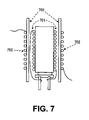
- FIG. 7 shows a pseudo cross-sectional view of an embodiment of an energy transfer element with two windings separated by an insulating sleeve according to the teachings of the present invention.
- FIG. 8 shows a pseudo cross-sectional view of an embodiment of an energy transfer element with two windings that are separated and covered by insulating sleeves according to the teachings of the present invention.
- FIG. 9 shows a pseudo cross-sectional view of an embodiment of an energy transfer element that is coated with a material having a magnetic permeability substantially greater than free space, covering two windings that are separated and covered by insulating sleeves, according to the teachings of the present invention.
- FIG. 10 is one embodiment of an electrical circuit diagram of a power converter circuit that employs an embodiment of the simple energy transfer element according to the teachings of the present invention.
- a method for constructing novel yet simple embodiments of energy transfer elements with two or more windings for transferring energy in power converters in accordance with the teachings of the present invention will now be described.
- the simple construction achieves low cost of manufacture through the use of a magnetic element with an open structure and the absence of a bobbin.
- the simple energy transfer elements reduce the cost of power converters and power supplies that deliver low output power, which will therefore reduce the manufacturing cost for low power electronic equipment in accordance with the teachings of the present invention. These reductions in cost are especially significant in circuits that use few components, where the cost of the energy transfer element contributes substantially to the total cost of the product.
- a first winding of ordinary magnet wire is wound on a magnetic element without a bobbin.
- a second winding of triple insulated wire is then wound directly over the first winding.
- the triple insulated wire allows the construction to meet the electrical isolation requirements of safety agencies.
- a first winding of ordinary magnet wire is wound on a magnetic element without a bobbin.
- the first winding is covered or encapsulated with an insulating coating.
- a second winding of ordinary magnet wire is wound directly over the encapsulation or insulating coating of the first winding.
- the encapsulation or the insulating coating allows the construction to meet the electrical isolation requirements of safety agencies, sparing the added expense of triple insulated wire.
- a first winding of ordinary magnet wire is wound on a magnetic element without a bobbin.
- a sleeve of insulating material is placed over the first winding.
- a second winding of ordinary magnet wire is wound directly on the sleeve that covers the first winding.
- a first winding of ordinary magnet wire is wound on a magnetic element without a bobbin.
- a sleeve of insulating material is placed over the first winding.
- the sleeve of insulating material has the property that it shrinks when heated.
- Application of appropriate heating causes the insulating sleeve to conform to the contours of the first winding and the surface of the magnetic element.
- a second winding of ordinary magnet wire is wound directly on the sleeve that covers the first winding.
- An additional sleeve of insulation is optionally applied to protect the second winding or to take a third winding. The technique can be extended to accommodate any number of sleeves and windings.
- Power converters for high power typically do not use magnetic elements with open structures.
- the open structures allow magnetic flux from the windings to couple to circuits in ways that are usually unpredictable and undesirable.
- power converters for high power typically use magnetic elements with closed magnetic structures.
- the closed structures substantially confine the magnetic flux to reduce the likelihood of undesirable coupling of magnetic flux from the windings. Undesirable coupling of magnetic flux from open magnetic structures is less likely in low power converters.
- a coating of material that has a magnetic permeability greater than free space is applied to the final winding or insulating sleeve.
- the coating is applied to a sufficient area and with a proper thickness to redirect and confine the magnetic flux from the windings. Redirection and confinement of the magnetic flux from the windings reduces the undesirable coupling of magnetic flux from the windings to circuits.
- FIG. 4 shows generally the functional elements included in for example a switched mode power converter, illustrating the role of various embodiments of energy transfer elements in accordance with the teachings of the present invention.
- Two separate and distinct functions are inherent in an electronic power supply.
- One is the function of power conversion, performed by a power converter.
- the other is the function of regulation, performed by a control mechanism acting on the power converter.
- the typical electronic power converter uses a connection of switches, energy storage elements and energy transfer elements to change the magnitude of one voltage or current to a different magnitude of voltage or current.
- a control mechanism senses the voltage or current to be regulated, compares the magnitude of the sensed voltage or current to the desired magnitude, and then adjusts the operation of the power converter in a way to reduce the error between the sensed voltage or current and the desired magnitude.
- an unregulated source 400 is coupled to a primary switched circuit 401 that contains one or more electrical components and switches.
- a switch is any component that can change its state of conduction between a first state that allows the conduction of electrical current and a second state that blocks conduction of electrical current.
- Switches can be mechanical components or electrical components. The switches may operate actively under external control or they can operate passively in response to the voltages that appear across them or the currents that pass through them.
- Primary switched circuit 401 is coupled to the electrical port P 1 of energy transfer element 402 .
- An electrical port is a pair of electrical conductors where energy may be supplied or withdrawn.
- An energy transfer element is a device with at least two electrical ports that allows energy to pass from one port to another port.
- energy transfer elements in power converters are magnetic devices that include a magnetic element with two or more windings.
- a magnetic element is any structure that has a magnetic permeability substantially greater than free space.
- a winding is an electrical conductor that couples magnetic flux.
- the energy transfer element 402 receives energy at its primary port P 1 from primary switched circuit 401 .
- the energy received at primary port P 1 is transferred to one or more secondary ports 403 .
- Secondary ports are shown in general as S 1 through S N in FIG. 4 .
- the secondary ports 403 deliver energy to one or more secondary switched circuits 404 .
- Each secondary port delivers energy to a secondary switched circuit that contains one or more electrical components and switches.
- the secondary switched circuits in FIG. 4 are designated SC 1 through SC N .
- the secondary switched circuits 404 are coupled to one or more loads 405 . Each secondary switched circuit is coupled to a load.
- the relationship between the voltage at the loads 405 and the voltage at the source 400 is determined by the design of the primary switched circuit 401 , the energy transfer element 402 and the secondary switched circuits 404 .
- a circuit or other mechanism is employed to adjust the operation of the switched circuits to maintain a desired voltage or current at one or more of the loads.
- the adjustments may be made to either the primary switched circuit 401 , the secondary switched circuits 404 , or to both 401 and 404 .
- the operation of the switched circuits may employ a variety of techniques. For instance, various embodiments include the switching to occur at a fixed frequency or at a variable frequency.
- the duty cycle of the switching waveforms may be varied using pulse width modulation.
- the frequency of the switching may be varied using a variety of techniques using for example a self-oscillating mode of operation or cycle skipping control. It is appreciated that other suitable types of techniques may be employed to adjust the operation of the switched circuits in power supplies in accordance with the teachings of the present invention.
- FIG. 5 illustrates one embodiment of an energy transfer element including a magnetic element 500 in a first cross section that represents an open rod structure that has a substantially cylindrical geometry.
- a second cross section perpendicular to the plane of the paper and perpendicular to the long sides 507 to reveal the features in the third dimension would show, in one embodiment, a substantially circular geometry for the magnetic element 500 .
- the external surface of one embodiment of magnetic element 500 is a substantially curved surface.
- a second cross section of magnetic element 500 perpendicular to the plane of the paper and perpendicular to the long sides 507 may be substantially polygonal such that an external surface of one embodiment of magnetic element 500 is substantially planar.
- the long sides 507 of the magnetic element 500 could be sections of planes with flat surfaces rather than curved surfaces.
- magnetic element 500 has an open structure with a section that can easily accept turns of wire that comprises a first winding 501 directly on its surface without a bobbin in accordance with the teachings of the present invention. The absence of a bobbin reduces the manufacturing cost in accordance with the teachings of the present invention.
- One embodiment of the present invention allows the turns of wire to be wound directly around an external surface of magnetic element 500 without the use of a bobbin.
- magnetic element 500 may include a coating to protect the external surface and to reduce abrasion of windings.
- a coating on the external surface of the magnetic element is an integral part of magnetic element 500 ; therefore, the surface of the coating shall have the same meaning as the surface of the magnetic element 500 in this disclosure.
- winding 501 is an ordinary magnet wire.
- magnet wire is typically a composition of one or more substances such as enamel, polyimide, nylon, polyurethane or similar insulating materials.
- the ends of the winding 501 are coupled to conductive pins 503 and 504 .
- an insulator 505 holds the conductive pins 503 and 504 .
- insulator 505 is attached to the magnetic element 500 by means of an adhesive 506 .
- the pins 503 and 504 are electrical terminals for the first winding 501 .
- Pins 503 and 504 also provide mechanical mounting for the energy transfer device when they are inserted into a circuit board.
- pins 503 and 504 can be held by means other than the single insulator 505 , and pins 503 and 504 can be attached at different places on magnetic element 500 .
- the energy transfer element does not include pins 503 and 504 and this embodiment may be employed in applications where it is desired to couple to the ends of the first winding 501 by a different means.
- a second winding 502 is applied directly over first winding 501 .
- the ends of second winding 502 are not coupled to pins. The absence of additional pins reduces the manufacturing cost.
- energy to be received from a power converter circuit input is to be transferred from the first winding 501 to the second winding 502 through a magnetic coupling provided between first and second windings 501 and 502 by the magnetic element 500 to a power converter circuit output.
- One embodiment of the present invention allows the turns of wire making up windings 501 and 502 to be wound directly around the external sufface of the magnetic element without having to thread the wire through an opening defined by the magnetic element 500 .
- a third winding 508 may also be wound around magnetic element 500 such that there is a magnetic coupling provided between first and third windings 501 and 508 by the magnetic element 500 .
- energy is transferred from the first winding 501 to the third winding 508 through the magnetic coupling provided between first and third windings 501 and 508 by the magnetic element 500 in accordance with the teachings of the present invention.
- two or more windings are wound around an external surface of magnetic element 500 without a bobbin in an energy transfer element in accordance with the teachings of the present invention.
- additional windings consisting of one or more turns can be used to provide additional power conversion circuit outputs or as shield windings to improve electromagnetic interference performance of the power conversion circuit in accordance with the teachings of the present invention. It is appreciated that the additional windings can be constructed of ordinary magnet wire or a conductive foil or tape or other suitable equivalents.
- the wire of winding 502 has three layers of insulation or triple insulated such that the requirements of safety agencies are met.
- triple insulated wire requires no additional insulating barrier to isolate a circuit coupled to a first winding from a circuit coupled to the triple insulated wire.
- the addition of an insulating material to separate the first winding from the second winding is employed, which allows the use of ordinary magnet wire for both first and second windings.
- the cost of ordinary magnet wire is generally substantially less than the cost of triple insulated wire. The total manufacturing cost can be reduced when there is a lower cost alternative to the use of triple insulated wire.
- FIG. 6 shows an embodiment of the present invention that includes a coating of insulating material 600 that separates the first winding 601 from the second winding 602 .
- the insulating material 600 is of sufficient dimension and dielectric strength to satisfy the requirements of safety agencies for electrical isolation between a first winding and a second winding.
- the first winding 601 and the second winding 602 are ordinary magnet wire.
- FIG. 7 shows one embodiment of the present invention that has a sleeve 700 of insulating material between a first winding 701 and a second winding 702 .
- the dielectric strength of the insulating material is sufficiently high and the length of the sleeve extends sufficiently past the winding 702 to meet the requirements of safety agencies for electrical isolation between a first winding and a second winding.
- the use of a sleeve 700 of insulating material is an alternative to the coating of insulating material 600 in the embodiment illustrated in FIG. 6 .
- the sleeve 700 of insulating material is a flexible tube of a crosslinked polymer that shrinks when it is heated to a temperature, known as the shrink temperature, which depends on the particular material.
- This product has the common name of heat shrink tubing.
- the heat shrink tubing undergoes a permanent reduction in size after it reaches the shrink temperature.
- the sleeve 700 after shrinking holds the first winding tightly to the magnetic element and forms a suitable surface to accept the turns of a second winding.
- FIG. 8 shows one embodiment of the present invention that uses a first sleeve that could be made of heat shrink tubing 800 to separate a first winding 801 from a second winding 802 .
- a second sleeve of heat shrink tubing 803 covers the second winding 802 .
- the dielectric strength of heat shrink tubing 800 is sufficiently high and the length of the heat shrink tubing 800 extends sufficiently past the winding 801 to meet the requirements of safety agencies for electrical isolation between a first winding 801 and a second winding 802 .
- FIG. 9 shows one embodiment of the present invention that has an exterior coating 900 of a material having magnetic permeability substantially greater than free space.
- the exterior coating 900 can be comprised of fine particles of magnetic material mixed with a nonmagnetic liquid such that the mixture is substantially homogeneous.
- the mixture is applied to the exterior of the energy transfer element by painting, dipping, or other suitable means according to various embodiments of the present invention.
- the mixture changes state from liquid to solid through a curing process that is completed after the exterior coating 900 is applied.
- the thickness of the exterior coating 900 and the extent that it covers the exterior surface are determined by the parameters of the manufacturing process.
- the thickness of the exterior coating 900 and the area that it covers are selected based on the effective permeability of the coating material to achieve the desired redirection and confinement of the magnetic flux from the windings.
- the thickness of the exterior coating 900 and the area that it covers can be selected to adjust the inductance of the windings.
- FIG. 10 is an electrical schematic diagram that shows generally one embodiment a power converter 1009 that is also a regulated power supply including an energy transfer element in accordance with the teachings of the present invention.
- a primary switched circuit 1000 couples an input voltage 1001 by means of the integrated circuit 1002 to a first port 1003 of the energy transfer element 1004 .
- input voltage 1001 is a DC voltage that has been provided with suitable rectification circuitry (not shown) from an AC input voltage using known techniques.
- Energy is transferred from the first port 1003 that is also a first winding of an energy transfer element in accordance with the teachings of the present invention to a second port 1005 of the energy transfer element.
- the second port 1005 is also a second winding of the present invention.
- the second port 1005 is coupled to the secondary switched circuit 1006 .
- secondary switched circuit 1006 produces a voltage 1007 that is to be coupled to an appropriate load.
- the integrated circuit 1002 includes a power supply regulator, which contains a power switch with the necessary control circuits to couple the input voltage 1001 with appropriate timing and duration to the first port 1003 in order to regulate the voltage 1007 .
- the voltage 1007 to be regulated is available to the integrated circuit 1002 at the first port 1003 of the energy transfer element 1004 .
- the electrical components in the primary switched circuit 1000 provide information from the first port 1003 to integrated circuit 1002 .
- the integrated circuit 1002 has an internal switch.
- integrated circuit 1002 uses the information from the components in the primary switched circuit 1000 to adjust the switching of the internal switch to achieve the desired regulation of the voltage 1007 and or the current flowing in switched circuit 1006 .
- the integrated circuit 1002 may use one of several control techniques in order to perform the function of adjusting the switching of the internal switch including fixed frequency PWM control, variable frequency control, variable frequency self oscillating control and cycle skipping control.
- control technique used by the integrated circuit 1002 is sometimes used to describe the operation of the overall power conversion circuit 1009 .
- input voltage 1001 is a DC input voltage.
Landscapes
- Engineering & Computer Science (AREA)
- Power Engineering (AREA)
- Dc-Dc Converters (AREA)
- Coils Of Transformers For General Uses (AREA)
- Insulating Of Coils (AREA)
- Power Conversion In General (AREA)
Priority Applications (7)
| Application Number | Priority Date | Filing Date | Title |
|---|---|---|---|
| US10/617,245 US7170381B2 (en) | 2003-07-09 | 2003-07-09 | Method and apparatus for transferring energy in a power converter circuit |
| EP04254055A EP1496526A3 (en) | 2003-07-09 | 2004-07-07 | Method and apparatus for transferring energy in a power converter circuit |
| JP2004202829A JP2005033209A (ja) | 2003-07-09 | 2004-07-09 | 電力変換器回路においてエネルギーを変換する方法と装置 |
| US11/070,434 US7170383B2 (en) | 2003-07-09 | 2005-03-01 | Method and apparatus for transferring energy in a power converter circuit |
| US11/201,031 US7205877B2 (en) | 2003-07-09 | 2005-08-10 | Method and apparatus for transferring energy in a power converter circuit |
| US11/716,110 US7482905B2 (en) | 2003-07-09 | 2007-03-08 | Method and apparatus for transferring energy in a power converter circuit |
| US12/349,414 US7924132B2 (en) | 2003-07-09 | 2009-01-06 | Method and apparatus for transferring energy in a power converter circuit |
Applications Claiming Priority (1)
| Application Number | Priority Date | Filing Date | Title |
|---|---|---|---|
| US10/617,245 US7170381B2 (en) | 2003-07-09 | 2003-07-09 | Method and apparatus for transferring energy in a power converter circuit |
Related Child Applications (2)
| Application Number | Title | Priority Date | Filing Date |
|---|---|---|---|
| US11/070,434 Division US7170383B2 (en) | 2003-07-09 | 2005-03-01 | Method and apparatus for transferring energy in a power converter circuit |
| US11/201,031 Division US7205877B2 (en) | 2003-07-09 | 2005-08-10 | Method and apparatus for transferring energy in a power converter circuit |
Publications (2)
| Publication Number | Publication Date |
|---|---|
| US20050007090A1 US20050007090A1 (en) | 2005-01-13 |
| US7170381B2 true US7170381B2 (en) | 2007-01-30 |
Family
ID=33452695
Family Applications (5)
| Application Number | Title | Priority Date | Filing Date |
|---|---|---|---|
| US10/617,245 Expired - Fee Related US7170381B2 (en) | 2003-07-09 | 2003-07-09 | Method and apparatus for transferring energy in a power converter circuit |
| US11/070,434 Expired - Fee Related US7170383B2 (en) | 2003-07-09 | 2005-03-01 | Method and apparatus for transferring energy in a power converter circuit |
| US11/201,031 Expired - Fee Related US7205877B2 (en) | 2003-07-09 | 2005-08-10 | Method and apparatus for transferring energy in a power converter circuit |
| US11/716,110 Expired - Fee Related US7482905B2 (en) | 2003-07-09 | 2007-03-08 | Method and apparatus for transferring energy in a power converter circuit |
| US12/349,414 Expired - Fee Related US7924132B2 (en) | 2003-07-09 | 2009-01-06 | Method and apparatus for transferring energy in a power converter circuit |
Family Applications After (4)
| Application Number | Title | Priority Date | Filing Date |
|---|---|---|---|
| US11/070,434 Expired - Fee Related US7170383B2 (en) | 2003-07-09 | 2005-03-01 | Method and apparatus for transferring energy in a power converter circuit |
| US11/201,031 Expired - Fee Related US7205877B2 (en) | 2003-07-09 | 2005-08-10 | Method and apparatus for transferring energy in a power converter circuit |
| US11/716,110 Expired - Fee Related US7482905B2 (en) | 2003-07-09 | 2007-03-08 | Method and apparatus for transferring energy in a power converter circuit |
| US12/349,414 Expired - Fee Related US7924132B2 (en) | 2003-07-09 | 2009-01-06 | Method and apparatus for transferring energy in a power converter circuit |
Country Status (3)
| Country | Link |
|---|---|
| US (5) | US7170381B2 (enExample) |
| EP (1) | EP1496526A3 (enExample) |
| JP (1) | JP2005033209A (enExample) |
Cited By (3)
| Publication number | Priority date | Publication date | Assignee | Title |
|---|---|---|---|---|
| US20100327212A1 (en) * | 2009-06-29 | 2010-12-30 | E. I. Du Pont De Nemours And Company | Propanediol soil resist compositions |
| US8570768B2 (en) | 2011-04-15 | 2013-10-29 | Power Integrations, Inc. | Low-cost transformer assembly |
| US12027295B2 (en) | 2018-05-31 | 2024-07-02 | Power Integrations, Inc. | Housing for ferrite beads and other pass-through electrical filter components |
Families Citing this family (11)
| Publication number | Priority date | Publication date | Assignee | Title |
|---|---|---|---|---|
| US7425834B2 (en) * | 2005-08-26 | 2008-09-16 | Power Integrations, Inc. | Method and apparatus to select a parameter/mode based on a time measurement |
| US8125802B2 (en) * | 2007-03-26 | 2012-02-28 | On-Bright Electronic (Shanghai) Co., Ltd. | Systems and methods for reducing EMI in switch mode converter systems |
| US7898376B2 (en) * | 2008-05-20 | 2011-03-01 | Sercomm Corporation | Transformer apparatus with shielding architecture and shielding method thereof |
| US8116106B2 (en) | 2008-09-19 | 2012-02-14 | Power Integrations, Inc. | Method and apparatus to select a parameter/mode based on a measurement during an initialization period |
| US8154371B2 (en) * | 2008-11-06 | 2012-04-10 | Power Integrations, Inc. | Method and apparatus for adjusting displacement current in an energy transfer element |
| CN103068708B (zh) * | 2010-08-17 | 2016-02-10 | 通力股份公司 | 电力供应设备以及电梯系统 |
| US8614615B2 (en) | 2010-12-01 | 2013-12-24 | Power Integrations, Inc. | Energy transfer assembly with tuned leakage inductance and common mode noise compensation |
| US9429595B2 (en) * | 2011-09-09 | 2016-08-30 | Aclara Meters Llc | Sensor devices and methods for use in sensing current through a conductor |
| JP2018094986A (ja) * | 2016-12-09 | 2018-06-21 | 株式会社デンソー | 電子制御装置 |
| JP2018170361A (ja) * | 2017-03-29 | 2018-11-01 | Tdk株式会社 | コイル部品 |
| FR3088497B1 (fr) | 2018-11-13 | 2021-05-07 | Renault Sas | Systeme de transfert d'une puissance electrique sans contact et procede associe |
Citations (9)
| Publication number | Priority date | Publication date | Assignee | Title |
|---|---|---|---|---|
| US5124681A (en) * | 1991-04-26 | 1992-06-23 | Delta Electronics, Inc. | Winding construction for a transformer |
| US5506764A (en) | 1994-01-31 | 1996-04-09 | Astec International, Ltd. | Electrical power converter with step-gapped transformer |
| US5719547A (en) * | 1994-08-12 | 1998-02-17 | Murata Manufacturing Co., Ltd. | Transformer with bifilar winding |
| US5737203A (en) | 1994-10-03 | 1998-04-07 | Delco Electronics Corp. | Controlled-K resonating transformer |
| US5760669A (en) * | 1994-12-02 | 1998-06-02 | Dale Electronics, Inc. | Low profile inductor/transformer component |
| US6535095B2 (en) | 2000-04-18 | 2003-03-18 | Taiyo Yuden Co., Ltd. | Wound type common mode choke coil |
| US6611187B2 (en) | 2000-10-25 | 2003-08-26 | Nec Tokin Corporation | Magnetic core, coil assembly and power supply circuit using the same |
| US20040164834A1 (en) * | 2001-07-03 | 2004-08-26 | Tolle Tobias Georg | Transformer |
| US7012414B1 (en) | 2004-08-19 | 2006-03-14 | Coldwatt, Inc. | Vertically packaged switched-mode power converter |
Family Cites Families (9)
| Publication number | Priority date | Publication date | Assignee | Title |
|---|---|---|---|---|
| US6611A (en) * | 1849-07-31 | Improvement in plows | ||
| DE1968695U (de) * | 1962-12-24 | 1967-09-21 | Siemens Ag | Hochfrequenztransformator fuer zuendgeraete von xenon- und quecksilberdampf-hochdruckentladungsgefaessen. |
| JPH02208908A (ja) | 1989-02-08 | 1990-08-20 | Murata Mfg Co Ltd | インダクタンス素子及びその製造方法 |
| DE9211148U1 (de) * | 1992-08-20 | 1993-02-25 | Zink, Manfred, 77723 Gengenbach | Hochfrequenz-Leistungstransformator |
| DE19803856A1 (de) * | 1998-01-31 | 1999-08-05 | Hella Kg Hueck & Co | Zündtransformator |
| JPH11340046A (ja) | 1998-05-22 | 1999-12-10 | Toko Inc | 複合インダクタンス素子 |
| US6392523B1 (en) * | 1999-01-25 | 2002-05-21 | Taiyo Yuden Co., Ltd. | Surface-mounting-type coil component |
| JP4039779B2 (ja) * | 1999-01-28 | 2008-01-30 | 太陽誘電株式会社 | チップ状電子部品の製造方法 |
| JP3659207B2 (ja) * | 2001-09-28 | 2005-06-15 | 松下電器産業株式会社 | インダクタンス素子 |
-
2003
- 2003-07-09 US US10/617,245 patent/US7170381B2/en not_active Expired - Fee Related
-
2004
- 2004-07-07 EP EP04254055A patent/EP1496526A3/en not_active Withdrawn
- 2004-07-09 JP JP2004202829A patent/JP2005033209A/ja active Pending
-
2005
- 2005-03-01 US US11/070,434 patent/US7170383B2/en not_active Expired - Fee Related
- 2005-08-10 US US11/201,031 patent/US7205877B2/en not_active Expired - Fee Related
-
2007
- 2007-03-08 US US11/716,110 patent/US7482905B2/en not_active Expired - Fee Related
-
2009
- 2009-01-06 US US12/349,414 patent/US7924132B2/en not_active Expired - Fee Related
Patent Citations (9)
| Publication number | Priority date | Publication date | Assignee | Title |
|---|---|---|---|---|
| US5124681A (en) * | 1991-04-26 | 1992-06-23 | Delta Electronics, Inc. | Winding construction for a transformer |
| US5506764A (en) | 1994-01-31 | 1996-04-09 | Astec International, Ltd. | Electrical power converter with step-gapped transformer |
| US5719547A (en) * | 1994-08-12 | 1998-02-17 | Murata Manufacturing Co., Ltd. | Transformer with bifilar winding |
| US5737203A (en) | 1994-10-03 | 1998-04-07 | Delco Electronics Corp. | Controlled-K resonating transformer |
| US5760669A (en) * | 1994-12-02 | 1998-06-02 | Dale Electronics, Inc. | Low profile inductor/transformer component |
| US6535095B2 (en) | 2000-04-18 | 2003-03-18 | Taiyo Yuden Co., Ltd. | Wound type common mode choke coil |
| US6611187B2 (en) | 2000-10-25 | 2003-08-26 | Nec Tokin Corporation | Magnetic core, coil assembly and power supply circuit using the same |
| US20040164834A1 (en) * | 2001-07-03 | 2004-08-26 | Tolle Tobias Georg | Transformer |
| US7012414B1 (en) | 2004-08-19 | 2006-03-14 | Coldwatt, Inc. | Vertically packaged switched-mode power converter |
Non-Patent Citations (6)
| Title |
|---|
| "Core Banding Data", Cut Cores Design Manual and Catalog (MCC-200), www.mag-inc.com/pdf/MCC-200.pdf, p. 5, Magnetics. |
| "Ferrites and Accessories", Data Book 1999, p. 565, Siemens Matsushita Components GmbH & Co. KG. |
| Close, Charles M., "The Analysis of Linear Circuits", Rensselaer Polytechnic Institute, 1966, p. 335, Figures 7.1-2 (a) and (c), Harcourt, Brace & World, Inc. |
| Col. McLyman, Wm. T., "Magnetic Core Selection for Transformers and Inductors", Jet Propulsion Laboratory, California Institute of Technology, 1997, p. 309 and 403, Figures 135 and 139, Marcel Dekker, Inc. |
| Erickson, Robert W. et al., "Fundamentals of Power Electronics", University of Colorado, 2001, p. 501, Figure 13.13, Kluwer Academic Publishers. |
| Watson, J.K., "Applications of Magnetism", University of Florida, 1980, Figure 6.40 (a), p. 277, John Wiley & Sons. |
Cited By (4)
| Publication number | Priority date | Publication date | Assignee | Title |
|---|---|---|---|---|
| US20100327212A1 (en) * | 2009-06-29 | 2010-12-30 | E. I. Du Pont De Nemours And Company | Propanediol soil resist compositions |
| US8570768B2 (en) | 2011-04-15 | 2013-10-29 | Power Integrations, Inc. | Low-cost transformer assembly |
| US9148959B2 (en) | 2011-04-15 | 2015-09-29 | Power Integrations, Inc. | Method of supplying power on a circuit board assembly |
| US12027295B2 (en) | 2018-05-31 | 2024-07-02 | Power Integrations, Inc. | Housing for ferrite beads and other pass-through electrical filter components |
Also Published As
| Publication number | Publication date |
|---|---|
| EP1496526A2 (en) | 2005-01-12 |
| US20050007090A1 (en) | 2005-01-13 |
| US20090153285A1 (en) | 2009-06-18 |
| US20060028782A1 (en) | 2006-02-09 |
| US20050146831A1 (en) | 2005-07-07 |
| US7482905B2 (en) | 2009-01-27 |
| US7170383B2 (en) | 2007-01-30 |
| US20080218146A1 (en) | 2008-09-11 |
| US7924132B2 (en) | 2011-04-12 |
| EP1496526A3 (en) | 2010-02-24 |
| US7205877B2 (en) | 2007-04-17 |
| JP2005033209A (ja) | 2005-02-03 |
Similar Documents
| Publication | Publication Date | Title |
|---|---|---|
| US7924132B2 (en) | Method and apparatus for transferring energy in a power converter circuit | |
| US7889043B2 (en) | Assembly structure of transformer, system circuit board and auxiliary circuit board | |
| US9148959B2 (en) | Method of supplying power on a circuit board assembly | |
| US6867678B2 (en) | Transformer structure | |
| US20190312516A1 (en) | Multiple parallel-connected resonant converter, inductor-integrated magnetic element and transformer-integrated magnetic element | |
| JP5813320B2 (ja) | 高電圧用途のための高周波変圧器 | |
| US20170117091A1 (en) | Power converter transformer with reduced leakage inductance | |
| US7218199B1 (en) | Structure of transformer | |
| EP1019923A2 (en) | Induction controlled voltage regulator | |
| WO2010095955A1 (en) | High voltage transformer | |
| US7023317B1 (en) | Cellular transformers | |
| US20160111201A1 (en) | Transformer | |
| TW446971B (en) | A switchable flux control for high power static electromagnetic devices | |
| US6278355B1 (en) | Transformer winding | |
| US4937546A (en) | Ring-core transformer | |
| EP3572846B1 (en) | High power transformer and transmitter for geophysical measurements | |
| US9136054B1 (en) | Reduced leakage inductance transformer and winding methods | |
| KR101218450B1 (ko) | 동축권선 변압기를 이용한 전력 추정 장치 | |
| FI82341B (fi) | Hoegspaenningstransformator foer en videoaotergivningsanordning. | |
| WO1989010621A1 (en) | Matrix transformer having high dielectric isolation | |
| EP3893256A1 (en) | Semi-planar transformer | |
| Quilici | Embedded magnetic power transformer | |
| US20230291106A1 (en) | Antenna device | |
| KR100522348B1 (ko) | 평면 인덕터 | |
| CN120165560A (zh) | 使用平面能量传递元件的集成电源 |
Legal Events
| Date | Code | Title | Description |
|---|---|---|---|
| AS | Assignment |
Owner name: POWER INTEGRATIONS, INC., CALIFORNIA Free format text: ASSIGNMENT OF ASSIGNORS INTEREST;ASSIGNORS:POLIVKA, WILLIAM M.;MATTHEWS, DAVID MICHAEL HUGH;REEL/FRAME:014276/0968 Effective date: 20030708 |
|
| FPAY | Fee payment |
Year of fee payment: 4 |
|
| REMI | Maintenance fee reminder mailed | ||
| LAPS | Lapse for failure to pay maintenance fees | ||
| STCH | Information on status: patent discontinuation |
Free format text: PATENT EXPIRED DUE TO NONPAYMENT OF MAINTENANCE FEES UNDER 37 CFR 1.362 |
|
| FP | Expired due to failure to pay maintenance fee |
Effective date: 20150130 |