US7131663B1 - Inflator for inflatable vehicle occupant protection device - Google Patents
Inflator for inflatable vehicle occupant protection device Download PDFInfo
- Publication number
- US7131663B1 US7131663B1 US09/371,776 US37177699A US7131663B1 US 7131663 B1 US7131663 B1 US 7131663B1 US 37177699 A US37177699 A US 37177699A US 7131663 B1 US7131663 B1 US 7131663B1
- Authority
- US
- United States
- Prior art keywords
- inflation fluid
- closure member
- container
- chamber
- rupturable closure
- Prior art date
- Legal status (The legal status is an assumption and is not a legal conclusion. Google has not performed a legal analysis and makes no representation as to the accuracy of the status listed.)
- Expired - Lifetime
Links
Images

Classifications
-
- B—PERFORMING OPERATIONS; TRANSPORTING
- B60—VEHICLES IN GENERAL
- B60R—VEHICLES, VEHICLE FITTINGS, OR VEHICLE PARTS, NOT OTHERWISE PROVIDED FOR
- B60R21/00—Arrangements or fittings on vehicles for protecting or preventing injuries to occupants or pedestrians in case of accidents or other traffic risks
- B60R21/02—Occupant safety arrangements or fittings, e.g. crash pads
- B60R21/16—Inflatable occupant restraints or confinements designed to inflate upon impact or impending impact, e.g. air bags
- B60R21/26—Inflatable occupant restraints or confinements designed to inflate upon impact or impending impact, e.g. air bags characterised by the inflation fluid source or means to control inflation fluid flow
- B60R21/268—Inflatable occupant restraints or confinements designed to inflate upon impact or impending impact, e.g. air bags characterised by the inflation fluid source or means to control inflation fluid flow using instantaneous release of stored pressurised gas
-
- B—PERFORMING OPERATIONS; TRANSPORTING
- B60—VEHICLES IN GENERAL
- B60R—VEHICLES, VEHICLE FITTINGS, OR VEHICLE PARTS, NOT OTHERWISE PROVIDED FOR
- B60R21/00—Arrangements or fittings on vehicles for protecting or preventing injuries to occupants or pedestrians in case of accidents or other traffic risks
- B60R2021/0002—Type of accident
- B60R2021/0018—Roll-over
-
- B—PERFORMING OPERATIONS; TRANSPORTING
- B60—VEHICLES IN GENERAL
- B60R—VEHICLES, VEHICLE FITTINGS, OR VEHICLE PARTS, NOT OTHERWISE PROVIDED FOR
- B60R21/00—Arrangements or fittings on vehicles for protecting or preventing injuries to occupants or pedestrians in case of accidents or other traffic risks
- B60R21/02—Occupant safety arrangements or fittings, e.g. crash pads
- B60R21/16—Inflatable occupant restraints or confinements designed to inflate upon impact or impending impact, e.g. air bags
- B60R21/26—Inflatable occupant restraints or confinements designed to inflate upon impact or impending impact, e.g. air bags characterised by the inflation fluid source or means to control inflation fluid flow
- B60R2021/26058—Inflatable occupant restraints or confinements designed to inflate upon impact or impending impact, e.g. air bags characterised by the inflation fluid source or means to control inflation fluid flow using a combination of inflators
-
- B—PERFORMING OPERATIONS; TRANSPORTING
- B60—VEHICLES IN GENERAL
- B60R—VEHICLES, VEHICLE FITTINGS, OR VEHICLE PARTS, NOT OTHERWISE PROVIDED FOR
- B60R21/00—Arrangements or fittings on vehicles for protecting or preventing injuries to occupants or pedestrians in case of accidents or other traffic risks
- B60R21/02—Occupant safety arrangements or fittings, e.g. crash pads
- B60R21/16—Inflatable occupant restraints or confinements designed to inflate upon impact or impending impact, e.g. air bags
- B60R21/26—Inflatable occupant restraints or confinements designed to inflate upon impact or impending impact, e.g. air bags characterised by the inflation fluid source or means to control inflation fluid flow
- B60R2021/26094—Inflatable occupant restraints or confinements designed to inflate upon impact or impending impact, e.g. air bags characterised by the inflation fluid source or means to control inflation fluid flow characterised by fluid flow controlling valves
-
- B—PERFORMING OPERATIONS; TRANSPORTING
- B60—VEHICLES IN GENERAL
- B60R—VEHICLES, VEHICLE FITTINGS, OR VEHICLE PARTS, NOT OTHERWISE PROVIDED FOR
- B60R21/00—Arrangements or fittings on vehicles for protecting or preventing injuries to occupants or pedestrians in case of accidents or other traffic risks
- B60R21/02—Occupant safety arrangements or fittings, e.g. crash pads
- B60R21/16—Inflatable occupant restraints or confinements designed to inflate upon impact or impending impact, e.g. air bags
- B60R21/26—Inflatable occupant restraints or confinements designed to inflate upon impact or impending impact, e.g. air bags characterised by the inflation fluid source or means to control inflation fluid flow
- B60R21/268—Inflatable occupant restraints or confinements designed to inflate upon impact or impending impact, e.g. air bags characterised by the inflation fluid source or means to control inflation fluid flow using instantaneous release of stored pressurised gas
- B60R2021/2685—Inflatable occupant restraints or confinements designed to inflate upon impact or impending impact, e.g. air bags characterised by the inflation fluid source or means to control inflation fluid flow using instantaneous release of stored pressurised gas comprising a plurality of pressure chambers
-
- B—PERFORMING OPERATIONS; TRANSPORTING
- B60—VEHICLES IN GENERAL
- B60R—VEHICLES, VEHICLE FITTINGS, OR VEHICLE PARTS, NOT OTHERWISE PROVIDED FOR
- B60R21/00—Arrangements or fittings on vehicles for protecting or preventing injuries to occupants or pedestrians in case of accidents or other traffic risks
- B60R21/02—Occupant safety arrangements or fittings, e.g. crash pads
- B60R21/16—Inflatable occupant restraints or confinements designed to inflate upon impact or impending impact, e.g. air bags
- B60R21/23—Inflatable members
- B60R21/231—Inflatable members characterised by their shape, construction or spatial configuration
- B60R21/232—Curtain-type airbags deploying mainly in a vertical direction from their top edge
-
- Y—GENERAL TAGGING OF NEW TECHNOLOGICAL DEVELOPMENTS; GENERAL TAGGING OF CROSS-SECTIONAL TECHNOLOGIES SPANNING OVER SEVERAL SECTIONS OF THE IPC; TECHNICAL SUBJECTS COVERED BY FORMER USPC CROSS-REFERENCE ART COLLECTIONS [XRACs] AND DIGESTS
- Y10—TECHNICAL SUBJECTS COVERED BY FORMER USPC
- Y10T—TECHNICAL SUBJECTS COVERED BY FORMER US CLASSIFICATION
- Y10T137/00—Fluid handling
- Y10T137/1624—Destructible or deformable element controlled
- Y10T137/1632—Destructible element
- Y10T137/1692—Rupture disc
- Y10T137/1714—Direct pressure causes disc to burst
- Y10T137/1729—Dome shape
- Y10T137/1737—Reverse buckling
Definitions
- the present invention relates to an inflator which provides inflation fluid to inflate an inflatable vehicle occupant protection device and, more specifically, to an inflator in which a rupturable closure member is supported.
- An inflatable vehicle occupant protection device such as a side curtain or an air bag, is inflated upon the occurrence of a vehicle condition requiring inflation of the side curtain or air bag.
- an inflator is actuated to provide inflation fluid which inflates the side curtain or air bag into the vehicle occupant compartment.
- the inflator includes a container defining an inflation fluid pressure chamber with an outlet passage.
- a rupturable closure member is fixed to the container to block flow of inflation fluid through the outlet passage.
- the inflator further includes an electrically actuatable initiator which, when actuated, causes the closure member to rupture so that inflation fluid in the pressure chamber can flow from the inflator.
- the present invention is an inflator for providing inflation fluid to inflate an inflatable vehicle occupant protection device.
- the inflator includes a container storing inflation fluid under pressure.
- the container has an outlet passage through which inflation fluid flows from the container.
- a rupturable closure member fixed to the container blocks flow of inflation fluid through the outlet passage.
- a support for the rupturable closure member defines a chamber adjacent the rupturable closure member.
- the rupturable closure member has a first portion deformed into the chamber by the pressure of the inflation fluid and a second ring-shaped portion encircling the first portion.
- An initiator ruptures the closure member by shearing the first portion from the second portion when actuated.
- FIG. 1 is a schematic illustration of a vehicle safety apparatus embodying the present invention
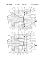
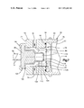
- FIG. 2 is an enlarged sectional view of an inflator of the safety apparatus of FIG. 1 ;
- FIG. 3 is an enlarged view of a portion of the inflator of FIG. 2 ;
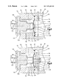
- FIG. 4 is a view similar to FIG. 3 showing a rupturable closure member prior to inflation fluid entering a container which is closed by the closure member;
- FIG. 5 is a view similar to FIG. 3 showing the closure member after an initiator of the inflator has been actuated;
- FIG. 6 is a view similar to FIG. 5 showing a portion of the closure member sheared away.
- FIG. 7 is a view similar to FIG. 6 showing the closure member during flow of inflation fluid from the container.
- the present invention relates to a vehicle occupant safety apparatus.
- the present invention relates to an inflatable vehicle occupant protection device, such as a side curtain assembly, for helping to protect a vehicle occupant in the event of a side impact to a vehicle.
- FIG. 1 illustrates schematically a vehicle safety apparatus 10 for helping to protect an occupant of a vehicle 12 .
- the safety apparatus 10 includes an inflatable vehicle occupant protection device in the form of a side curtain 14 .
- the side curtain 14 is mounted adjacent the side structure 16 of the vehicle 12 .
- a fill tube 20 extends into the side curtain 14 .
- An actuatable inflator 22 when actuated, directs fluid into the fill tube 20 which, in turn, directs fluid into the inflatable side curtain 14 to inflate the side curtain.
- the side curtain 14 is inflated from a deflated and stowed condition (not shown) to an inflated condition, as illustrated in FIG. 1 . In its inflated condition, the side curtain 14 is positioned between the side structure of the vehicle and a vehicle occupant.
- the side curtain 14 is made of a material having a low permeability so that the side curtain remains inflated for a long period of time, such as seven seconds or longer.
- the vehicle 12 includes a sensor 24 , known in the art, for sensing a side impact to the vehicle and/or a vehicle rollover, to actuate the inflator 22 .
- the sensor 24 may include vehicle electric circuitry for actuating the inflator 22 in response to sensing a side impact to the vehicle and/or a vehicle rollover.
- the sensor 24 provides an electric signal over lead wires 26 to the inflator 22 , when the inflator is to be actuated.
- the inflator 22 ( FIG. 2 ) comprises a source of inflation fluid for the side curtain 14 .
- the inflator 22 includes a container 30 having a generally elongate configuration including a main body portion 32 and an end cap 34 .
- the end cap 34 is affixed to an open end 33 of the main body portion 32 by friction welding.
- the end cap 34 could, however, be connected to the main body portion 32 in any manner known in the art, such as using laser welds, brazing or screw threads.
- the main body portion 32 of the container 30 has a tubular, cylindrical configuration including an axially extending cylindrical side wall 40 .
- the side wall 40 has a cylindrical inner surface 42 centered on a longitudinal central axis 44 of the inflator 22 .
- a second end portion 46 of the main body portion 32 is closed by a domed end wall 48 .
- the side wall 40 and the end wall 48 define a chamber 50 in the container 30 .
- the chamber 50 contains pressurized inflation fluid.
- the inflation fluid stored in the chamber 50 preferably consists essentially of helium at a storage pressure within the range of about 4,000 psi to about 7,000 psi.
- the inflation fluid may, however, have any other composition and storage pressure suitable for inflating the side curtain 14 .
- the end cap 34 ( FIGS. 2 and 3 ) of the container 30 has a generally cylindrical configuration including an axially extending cylindrical side wall 70 and an end surface 72 .
- An annular array of inflation fluid outlet passages 76 are formed in the side wall 70 of the end cap 34 .
- the flow area, number and/or configuration of the outlet passages 76 may be selected to restrict or otherwise control the flow of inflation fluid into the side curtain 14 through the fill tube 20 , which is connected in a known manner to the end cap 34 , as illustrated schematically in FIG. 1 .
- the end cap 34 includes a surface 78 ( FIG. 2 ) which extends generally parallel to the end surface 72 .
- a passage 80 extends axially through the end cap 34 and intersects the surface 78 .
- the passage 80 conducts inflation fluid from the chamber 50 to the outlet passages 76 .
- the passage 80 is centered on the axis 44 .
- a rupturable closure member 92 ( FIGS. 2 and 3 ), such as a rupture disk, is affixed to the surface 78 by a laser weld 94 .
- the rupture disk 92 could, however, be connected to the surface 78 in any manner well known in the art, such as by brazing, projection welding or electron beam welding.
- the rupture disk 92 is centered on the axis 44 and blocks the flow of inflation fluid through the passage 80 and to the passages 76 .
- An initiator 98 centered on the axis 44 is housed in a hollow support 100 which supports the closure member 92 .
- Lead wires 26 extend from connector pins 101 of the initiator 98 to receive the electrical signal from the sensor 24 .
- the support 100 is centered on the axis 44 .
- the support 100 ( FIGS. 2 and 3 ) has a flange 102 which engages the end surface 72 of the end cap 34 .
- the flange 102 extends radially outward of the support 100 and also engages a radially extending base 104 of the initiator 98 .
- An annular rim portion 106 extends from the end surface 72 .
- the rim portion 106 initially projects axially away from the end surface 72 and is subsequently crimped around the base 104 of the initiator 98 to hold the initiator and the support 100 in place in the end cap 34 .
- the initiator 98 and the support 100 may be welded to the end cap 34 to retain the initiator and the support in the end cap.
- the support 100 projects inwardly along the axis 44 into abutment with the closure member 92 .
- the support 100 is thus mounted in a load bearing relationship with the closure member 92 .
- the closure member 92 is subjected to the storage pressure of the inflation fluid in the chamber 50 . Therefore, the closure member 92 transmits a fluid storage pressure force axially outward against the support 100 .
- the support 100 transmits the storage pressure force to the end surface 72 of the end cap 34 where the initiator 98 adjoins the crimped rim 106 of the end surface 72 .
- the support 100 defines a chamber 110 .
- An end portion 112 of the support 100 has a circular rim 114 engaging the closure member 92 .
- the rim 114 defines an opening 116 into the chamber 110 .
- the closure member 92 has a central dome-shaped portion 122 extending into the chamber 110 .
- a portion 124 of the closure member 92 encircles the dome-shaped portion 122 .
- the portion 124 of the closure member 92 extends from the circular rim 114 of the support 100 to the surface 78 of the end cap 34 .
- a portion 126 of the closure member 92 encircles the portion 124 and is welded to the surface 78 .
- the closure member 92 When the chamber 50 is not filled with inflation fluid, as shown in FIG. 4 , the closure member 92 is a flat disk. The closure member 92 is spaced from the rim 114 of the support 100 . During the subsequent loading of the closure member 92 by the pressure of the inflation fluid, the closure member is stressed and undergoes plastic deformation into the chamber 110 . The closure member 92 deforms from the flat disk shown in FIG. 4 into the shape shown in FIG. 3 . A work hardening of the closure member 92 occurs during the plastic deformation.
- the initiator 98 Upon receiving of an electric signal from the sensor 24 , the initiator 98 is actuated in a known manner to produce a shock wave and combustion gas.
- the large movement of the dome 122 shears the dome out of the closure member 92 , as shown in FIG. 6 .
- the portion 124 of the closure member 92 continues to block the passage 80 .
- the pressure generated by the inflation fluid is supported only by the strength of the portion 124 when the dome 122 is removed.
- the pressure of the inflation fluid causes the portion 124 of the closure member 92 to rip and petal away from the support 100 to the position shown in FIG. 7 , providing a flow of the inflation fluid through the passage 80 and to the outlet passages 76 and thereafter to the side curtain 14 .
- the inflator 22 is shown being used with a side curtain 14 , the inflator could be used in any known inflatable vehicle occupant protection device such as air bags, inflatable seat belts, inflatable knee bolsters, inflatable air bags to operate knee bolsters, and inflatable head liners.
- any known inflatable vehicle occupant protection device such as air bags, inflatable seat belts, inflatable knee bolsters, inflatable air bags to operate knee bolsters, and inflatable head liners.
Landscapes
- Physics & Mathematics (AREA)
- Fluid Mechanics (AREA)
- Engineering & Computer Science (AREA)
- Mechanical Engineering (AREA)
- Air Bags (AREA)
Priority Applications (12)
| Application Number | Priority Date | Filing Date | Title |
|---|---|---|---|
| US09/371,776 US7131663B1 (en) | 1999-08-10 | 1999-08-10 | Inflator for inflatable vehicle occupant protection device |
| DE20023934U DE20023934U1 (de) | 1999-08-10 | 2000-06-07 | Aufblasvorrichtung |
| DE20010176U DE20010176U1 (de) | 1999-08-10 | 2000-06-07 | Aufblasvorrichtung |
| EP00112245A EP1075988B1 (de) | 1999-08-10 | 2000-06-07 | Gasgenerator mit aufreissbarem Verschlusselement |
| DE60041012T DE60041012D1 (de) | 1999-08-10 | 2000-06-07 | Seitenairbag-Vorrichtung |
| DE60036902T DE60036902T2 (de) | 1999-08-10 | 2000-06-07 | Gasgenerator mit aufreissbarem Verschlusselement |
| US09/589,341 US6412811B1 (en) | 1999-02-26 | 2000-06-07 | Inflator |
| EP05019891A EP1602536B1 (de) | 1999-08-10 | 2000-06-07 | Seitenairbag-Vorrichtung |
| JP2000173388A JP3488183B2 (ja) | 1999-08-10 | 2000-06-09 | 膨張流体提供装置 |
| DE2000138676 DE10038676B4 (de) | 1999-08-10 | 2000-08-08 | Aufblasvorrichtung |
| US10/273,971 US6908106B2 (en) | 1999-08-10 | 2002-10-18 | Inflator |
| US11/057,487 US7121582B2 (en) | 1999-08-10 | 2005-02-14 | Inflator |
Applications Claiming Priority (1)
| Application Number | Priority Date | Filing Date | Title |
|---|---|---|---|
| US09/371,776 US7131663B1 (en) | 1999-08-10 | 1999-08-10 | Inflator for inflatable vehicle occupant protection device |
Related Child Applications (3)
| Application Number | Title | Priority Date | Filing Date |
|---|---|---|---|
| US09/259,362 Continuation-In-Part US6227562B1 (en) | 1999-02-26 | 1999-02-26 | Stored gas inflator assembly |
| US10/273,971 Division US6908106B2 (en) | 1999-08-10 | 2002-10-18 | Inflator |
| US11/057,487 Continuation US7121582B2 (en) | 1999-08-10 | 2005-02-14 | Inflator |
Publications (1)
| Publication Number | Publication Date |
|---|---|
| US7131663B1 true US7131663B1 (en) | 2006-11-07 |
Family
ID=23465361
Family Applications (3)
| Application Number | Title | Priority Date | Filing Date |
|---|---|---|---|
| US09/371,776 Expired - Lifetime US7131663B1 (en) | 1999-02-26 | 1999-08-10 | Inflator for inflatable vehicle occupant protection device |
| US10/273,971 Expired - Lifetime US6908106B2 (en) | 1999-08-10 | 2002-10-18 | Inflator |
| US11/057,487 Expired - Lifetime US7121582B2 (en) | 1999-08-10 | 2005-02-14 | Inflator |
Family Applications After (2)
| Application Number | Title | Priority Date | Filing Date |
|---|---|---|---|
| US10/273,971 Expired - Lifetime US6908106B2 (en) | 1999-08-10 | 2002-10-18 | Inflator |
| US11/057,487 Expired - Lifetime US7121582B2 (en) | 1999-08-10 | 2005-02-14 | Inflator |
Country Status (4)
| Country | Link |
|---|---|
| US (3) | US7131663B1 (de) |
| EP (2) | EP1075988B1 (de) |
| JP (1) | JP3488183B2 (de) |
| DE (4) | DE60036902T2 (de) |
Cited By (6)
| Publication number | Priority date | Publication date | Assignee | Title |
|---|---|---|---|---|
| US20060103123A1 (en) * | 2004-11-12 | 2006-05-18 | Trw Vehicle Safety Systems Inc. | Inflator with shock wave focusing structure |
| US20080156223A1 (en) * | 2006-12-29 | 2008-07-03 | Patterson Donald B | Hybrid gas generator |
| US20090020990A1 (en) * | 2007-07-22 | 2009-01-22 | Key Safety Systems, Inc. | Venting device for an airbag inflator |
| US20100071581A1 (en) * | 2008-09-25 | 2010-03-25 | Toyoda Gosei Co., Ltd., | Gas generator |
| US20100127486A1 (en) * | 2008-11-25 | 2010-05-27 | Toyoda Gosei Co., Ltd. | Inflator |
| US9908501B2 (en) | 2014-01-28 | 2018-03-06 | Robert Bosch Gmbh | Device for controlling a volumetric flow rate of a medium stored under pressure in order to activate an impact protection device, and device for activating an impact protection device |
Families Citing this family (21)
| Publication number | Priority date | Publication date | Assignee | Title |
|---|---|---|---|---|
| EP1346885B1 (de) | 2000-12-27 | 2008-11-12 | Daicel Chemical Industries, Ltd. | Aufblasvorrichtung |
| DE20114664U1 (de) | 2001-09-05 | 2002-01-17 | TRW Airbag Systems GmbH & Co. KG, 84544 Aschau | Hybrid-Gasgenerator |
| US7032925B2 (en) | 2001-12-14 | 2006-04-25 | Daicel Chemical Industries, Ltd. | Rupturable plate for inflator |
| JP2003182506A (ja) * | 2001-12-14 | 2003-07-03 | Daicel Chem Ind Ltd | インフレータ用破裂板 |
| US6726243B2 (en) * | 2002-05-31 | 2004-04-27 | Autoliv Asp, Inc. | Tuning the performance of compressed gas-containing inflators |
| US7044501B2 (en) | 2002-06-17 | 2006-05-16 | Daicel Chemical Industries, Ltd. | Inflator |
| JP3996806B2 (ja) * | 2002-06-17 | 2007-10-24 | ダイセル化学工業株式会社 | インフレータ |
| US20040009107A1 (en) * | 2002-07-12 | 2004-01-15 | Universal Propulsion Company, Inc. | Aircraft evacuation slide inflator using a catalytically decomposed gas |
| US7175198B2 (en) | 2002-08-20 | 2007-02-13 | Daicel Chemical Industries, Ltd. | Inflator |
| JP2004074947A (ja) * | 2002-08-20 | 2004-03-11 | Daicel Chem Ind Ltd | インフレータ |
| ES1052998Y (es) * | 2002-10-03 | 2003-06-16 | Talleres Mecanicos Mafra S L | Dispositivo de seguridad mediante disco de rotura con presion de tarado multiple. |
| DE10318888B3 (de) * | 2003-04-17 | 2004-10-28 | Takata-Petri (Ulm) Gmbh | Gasgenerator für ein Insassenschutzsystem eines Fahrzeugs |
| US7226078B2 (en) * | 2004-08-27 | 2007-06-05 | Autoliv Asp, Inc. | Inflator projectile |
| US7597354B2 (en) * | 2004-10-28 | 2009-10-06 | Automotive Systems Laboratory, Inc. | Pressurized gas release mechanism |
| DE102007010066A1 (de) * | 2007-02-28 | 2008-09-18 | Autoliv Development Ab | Aufblasvorrichtung |
| US7878535B2 (en) * | 2008-04-29 | 2011-02-01 | Arc Automotive, Inc. | Airbag inflator with adaptive valve |
| US8205631B2 (en) * | 2008-11-19 | 2012-06-26 | Autoliv Asp, Inc. | Active material actuated vent valve |
| FR2983807B1 (fr) * | 2011-12-13 | 2014-04-25 | Autoliv Dev | Generateur de gaz |
| GB201707283D0 (en) * | 2014-11-09 | 2017-06-21 | Hip Hope Tech Ltd | Air bag mechanism |
| JP6467232B2 (ja) | 2015-01-27 | 2019-02-06 | 株式会社ダイセル | ガス発生器用の閉塞部材の支持構造とそれを使用したガス発生器 |
| JP6880505B2 (ja) * | 2017-07-14 | 2021-06-02 | 株式会社ダイセル | 放出装置、及びガス発生器 |
Citations (39)
| Publication number | Priority date | Publication date | Assignee | Title |
|---|---|---|---|---|
| US3648898A (en) * | 1971-01-06 | 1972-03-14 | Gen Motors Corp | Sensor and trigger mechanism |
| US3680886A (en) | 1969-12-16 | 1972-08-01 | Ara Inc | Safety cushion air system |
| US3724870A (en) | 1970-02-18 | 1973-04-03 | Asahi Chemical Ind | Gas-producing device for an inflatable body-protecting bag on a high-speed vehicle |
| US3773351A (en) | 1971-08-02 | 1973-11-20 | Timmerman H | Gas generator |
| JPS4891611A (de) | 1972-02-07 | 1973-11-28 | ||
| US3884497A (en) | 1973-10-30 | 1975-05-20 | Allied Chem | Inflation differential control for multiple bag restraint system |
| US5031932A (en) | 1990-04-05 | 1991-07-16 | Frantom Richard L | Single pyrotechnic hybrid inflator |
| US5242194A (en) * | 1992-10-23 | 1993-09-07 | Trw Vehicle Safety Systems Inc. | Air bag inflator |
| US5263740A (en) | 1991-12-17 | 1993-11-23 | Trw Inc. | Hybrid air bag inflator |
| US5351989A (en) * | 1992-11-30 | 1994-10-04 | Trw Vehicle Safety Systems Inc. | Inflator assembly |
| US5468015A (en) * | 1994-06-21 | 1995-11-21 | Trw Vehicle Safety Systems Inc. | Apparatus for inflating an inflatable vehicle occupant restraint |
| US5536040A (en) | 1995-04-24 | 1996-07-16 | Trw Inc. | Inflator for side impact air bag |
| US5564740A (en) * | 1995-03-09 | 1996-10-15 | Trw Inc. | Air bag inflator |
| US5573271A (en) | 1994-11-18 | 1996-11-12 | Trw Inc. | Side impact air bag inflator |
| US5593180A (en) | 1995-04-24 | 1997-01-14 | Trw Inc. | Dual chamber inflator for side impact air bag |
| US5603525A (en) | 1995-06-22 | 1997-02-18 | Trw Inc. | Air bag inflator initiator housing with stored fluid pressure relief |
| US5618057A (en) | 1995-09-15 | 1997-04-08 | Morton International, Inc. | Continuously variable controlled orifice inflator |
| US5678856A (en) * | 1995-06-28 | 1997-10-21 | Trw Inc. | Exploding foil initiator for air bag inflator |
| GB2314300A (en) | 1996-06-20 | 1997-12-24 | Autoliv Dev | Airbag having tubular conduit folded back on itself for delivery of inflation gas. |
| US5709406A (en) | 1996-02-28 | 1998-01-20 | Morton International, Inc. | Hybrid inflator with projectile gas release |
| GB2316475A (en) | 1996-08-14 | 1998-02-25 | Autoliv Dev | A gas generator arrangement for an airbag and a method of inflating an airbag |
| JPH10157551A (ja) | 1996-11-26 | 1998-06-16 | Toyo Tire & Rubber Co Ltd | 側部用エアバッグ装置 |
| US5794973A (en) | 1996-12-04 | 1998-08-18 | Trw Vehicle Safety Systems Inc. | Dual stage air bag inflator |
| US5863066A (en) | 1997-03-13 | 1999-01-26 | Trw Vehicle Safety Systems Inc. | Multiple stage air bag inflator |
| US5907120A (en) | 1996-06-17 | 1999-05-25 | Hi Shear Technology Corporation | Inflator for vehicle air bags |
| US5967550A (en) | 1997-10-07 | 1999-10-19 | Trw Inc. | Staged pyrotechnic air bag inflator |
| US5984348A (en) | 1997-06-13 | 1999-11-16 | Breed Automotive Technology, Inc. | Device for protecting against a side impact in a motor vehicle |
| US6010153A (en) * | 1997-02-21 | 2000-01-04 | Breed Automotive Technology, Inc. | Hybrid inflator for airbags |
| US6010152A (en) | 1998-03-31 | 2000-01-04 | Trw Inc. | Air bag inflator |
| US6029995A (en) | 1998-04-09 | 2000-02-29 | Trw Vehicle Safety Systems Inc. | Vehicle occupant protection apparatus |
| US6056316A (en) * | 1996-10-03 | 2000-05-02 | Toyo Tire & Rubber Co., Ltd. | Side air bag |
| US6062599A (en) | 1998-05-12 | 2000-05-16 | Trw Vehicle Safety Systems Inc. | Air bag inflator |
| US6073961A (en) | 1998-02-20 | 2000-06-13 | Breed Automotive Technology, Inc. | Inflatable side airbag curtain module |
| US6142508A (en) * | 1996-06-03 | 2000-11-07 | Universal Propulsion Company, Inc. | Side impact air bag system |
| US6145876A (en) * | 1998-10-23 | 2000-11-14 | Oea, Inc. | Vehicle inflator with stored gas for supplementing inflation |
| US6206420B1 (en) | 1995-10-31 | 2001-03-27 | Autoliv Development Ab | Device for introducing pressurized gas into a vehicle safety device |
| US6217065B1 (en) * | 1999-08-10 | 2001-04-17 | Trw Inc. | Inflator |
| US6227562B1 (en) | 1999-02-26 | 2001-05-08 | Trw Inc. | Stored gas inflator assembly |
| US6231078B1 (en) * | 1998-04-08 | 2001-05-15 | Takata Corporation | Air bag inflator |
Family Cites Families (7)
| Publication number | Priority date | Publication date | Assignee | Title |
|---|---|---|---|---|
| US3804435A (en) * | 1971-09-15 | 1974-04-16 | Caterpillar Tractor Co | Vehicle roll-over safety apparatus |
| US3724879A (en) * | 1971-11-22 | 1973-04-03 | C Snyder | Tubing coupling |
| US5632505A (en) * | 1995-06-29 | 1997-05-27 | Trw Vehicle Safety Systems Inc. | Pressure vessel with rupturable closure wall |
| US5826904A (en) * | 1996-06-10 | 1998-10-27 | Morton International, Inc. | Directional compressed gas inflator |
| JPH1071922A (ja) * | 1996-06-26 | 1998-03-17 | Nissan Motor Co Ltd | ガス発生器 |
| US6412811B1 (en) * | 1999-02-26 | 2002-07-02 | Trw Inc. | Inflator |
| US6176249B1 (en) * | 1999-08-10 | 2001-01-23 | Trw Inc. | Inflator |
-
1999
- 1999-08-10 US US09/371,776 patent/US7131663B1/en not_active Expired - Lifetime
-
2000
- 2000-06-07 EP EP00112245A patent/EP1075988B1/de not_active Expired - Lifetime
- 2000-06-07 DE DE60036902T patent/DE60036902T2/de not_active Expired - Lifetime
- 2000-06-07 EP EP05019891A patent/EP1602536B1/de not_active Expired - Lifetime
- 2000-06-07 DE DE20023934U patent/DE20023934U1/de not_active Expired - Lifetime
- 2000-06-07 DE DE60041012T patent/DE60041012D1/de not_active Expired - Lifetime
- 2000-06-07 DE DE20010176U patent/DE20010176U1/de not_active Expired - Lifetime
- 2000-06-09 JP JP2000173388A patent/JP3488183B2/ja not_active Expired - Fee Related
-
2002
- 2002-10-18 US US10/273,971 patent/US6908106B2/en not_active Expired - Lifetime
-
2005
- 2005-02-14 US US11/057,487 patent/US7121582B2/en not_active Expired - Lifetime
Patent Citations (41)
| Publication number | Priority date | Publication date | Assignee | Title |
|---|---|---|---|---|
| US3680886A (en) | 1969-12-16 | 1972-08-01 | Ara Inc | Safety cushion air system |
| US3724870A (en) | 1970-02-18 | 1973-04-03 | Asahi Chemical Ind | Gas-producing device for an inflatable body-protecting bag on a high-speed vehicle |
| US3648898A (en) * | 1971-01-06 | 1972-03-14 | Gen Motors Corp | Sensor and trigger mechanism |
| US3773351A (en) | 1971-08-02 | 1973-11-20 | Timmerman H | Gas generator |
| JPS4891611A (de) | 1972-02-07 | 1973-11-28 | ||
| US3806153A (en) | 1972-02-07 | 1974-04-23 | Olin Corp | Safety bag inflation for vehicles |
| US3884497A (en) | 1973-10-30 | 1975-05-20 | Allied Chem | Inflation differential control for multiple bag restraint system |
| US5031932A (en) | 1990-04-05 | 1991-07-16 | Frantom Richard L | Single pyrotechnic hybrid inflator |
| WO1991015381A1 (en) | 1990-04-05 | 1991-10-17 | Bendix Atlantic Inflator Company | Gas bag inflator |
| US5263740A (en) | 1991-12-17 | 1993-11-23 | Trw Inc. | Hybrid air bag inflator |
| US5242194A (en) * | 1992-10-23 | 1993-09-07 | Trw Vehicle Safety Systems Inc. | Air bag inflator |
| US5351989A (en) * | 1992-11-30 | 1994-10-04 | Trw Vehicle Safety Systems Inc. | Inflator assembly |
| US5468015A (en) * | 1994-06-21 | 1995-11-21 | Trw Vehicle Safety Systems Inc. | Apparatus for inflating an inflatable vehicle occupant restraint |
| US5573271A (en) | 1994-11-18 | 1996-11-12 | Trw Inc. | Side impact air bag inflator |
| US5564740A (en) * | 1995-03-09 | 1996-10-15 | Trw Inc. | Air bag inflator |
| US5536040A (en) | 1995-04-24 | 1996-07-16 | Trw Inc. | Inflator for side impact air bag |
| US5593180A (en) | 1995-04-24 | 1997-01-14 | Trw Inc. | Dual chamber inflator for side impact air bag |
| US5603525A (en) | 1995-06-22 | 1997-02-18 | Trw Inc. | Air bag inflator initiator housing with stored fluid pressure relief |
| US5678856A (en) * | 1995-06-28 | 1997-10-21 | Trw Inc. | Exploding foil initiator for air bag inflator |
| US5618057A (en) | 1995-09-15 | 1997-04-08 | Morton International, Inc. | Continuously variable controlled orifice inflator |
| US6206420B1 (en) | 1995-10-31 | 2001-03-27 | Autoliv Development Ab | Device for introducing pressurized gas into a vehicle safety device |
| US5709406A (en) | 1996-02-28 | 1998-01-20 | Morton International, Inc. | Hybrid inflator with projectile gas release |
| US6142508A (en) * | 1996-06-03 | 2000-11-07 | Universal Propulsion Company, Inc. | Side impact air bag system |
| US5907120A (en) | 1996-06-17 | 1999-05-25 | Hi Shear Technology Corporation | Inflator for vehicle air bags |
| GB2314300A (en) | 1996-06-20 | 1997-12-24 | Autoliv Dev | Airbag having tubular conduit folded back on itself for delivery of inflation gas. |
| GB2316475A (en) | 1996-08-14 | 1998-02-25 | Autoliv Dev | A gas generator arrangement for an airbag and a method of inflating an airbag |
| US6056316A (en) * | 1996-10-03 | 2000-05-02 | Toyo Tire & Rubber Co., Ltd. | Side air bag |
| JPH10157551A (ja) | 1996-11-26 | 1998-06-16 | Toyo Tire & Rubber Co Ltd | 側部用エアバッグ装置 |
| US5794973A (en) | 1996-12-04 | 1998-08-18 | Trw Vehicle Safety Systems Inc. | Dual stage air bag inflator |
| US6010153A (en) * | 1997-02-21 | 2000-01-04 | Breed Automotive Technology, Inc. | Hybrid inflator for airbags |
| US5863066A (en) | 1997-03-13 | 1999-01-26 | Trw Vehicle Safety Systems Inc. | Multiple stage air bag inflator |
| US5984348A (en) | 1997-06-13 | 1999-11-16 | Breed Automotive Technology, Inc. | Device for protecting against a side impact in a motor vehicle |
| US5967550A (en) | 1997-10-07 | 1999-10-19 | Trw Inc. | Staged pyrotechnic air bag inflator |
| US6073961A (en) | 1998-02-20 | 2000-06-13 | Breed Automotive Technology, Inc. | Inflatable side airbag curtain module |
| US6010152A (en) | 1998-03-31 | 2000-01-04 | Trw Inc. | Air bag inflator |
| US6231078B1 (en) * | 1998-04-08 | 2001-05-15 | Takata Corporation | Air bag inflator |
| US6029995A (en) | 1998-04-09 | 2000-02-29 | Trw Vehicle Safety Systems Inc. | Vehicle occupant protection apparatus |
| US6062599A (en) | 1998-05-12 | 2000-05-16 | Trw Vehicle Safety Systems Inc. | Air bag inflator |
| US6145876A (en) * | 1998-10-23 | 2000-11-14 | Oea, Inc. | Vehicle inflator with stored gas for supplementing inflation |
| US6227562B1 (en) | 1999-02-26 | 2001-05-08 | Trw Inc. | Stored gas inflator assembly |
| US6217065B1 (en) * | 1999-08-10 | 2001-04-17 | Trw Inc. | Inflator |
Cited By (9)
| Publication number | Priority date | Publication date | Assignee | Title |
|---|---|---|---|---|
| US20060103123A1 (en) * | 2004-11-12 | 2006-05-18 | Trw Vehicle Safety Systems Inc. | Inflator with shock wave focusing structure |
| US20080156223A1 (en) * | 2006-12-29 | 2008-07-03 | Patterson Donald B | Hybrid gas generator |
| US7739957B2 (en) | 2006-12-29 | 2010-06-22 | Tk Holdings, Inc. | Hybrid gas generator |
| US20090020990A1 (en) * | 2007-07-22 | 2009-01-22 | Key Safety Systems, Inc. | Venting device for an airbag inflator |
| US7658406B2 (en) | 2007-07-22 | 2010-02-09 | Key Safety Systems, Inc. | Venting device for an airbag inflator |
| US20100071581A1 (en) * | 2008-09-25 | 2010-03-25 | Toyoda Gosei Co., Ltd., | Gas generator |
| US8136452B2 (en) | 2008-09-25 | 2012-03-20 | Toyoda Gosei Co., Ltd. | Gas generator |
| US20100127486A1 (en) * | 2008-11-25 | 2010-05-27 | Toyoda Gosei Co., Ltd. | Inflator |
| US9908501B2 (en) | 2014-01-28 | 2018-03-06 | Robert Bosch Gmbh | Device for controlling a volumetric flow rate of a medium stored under pressure in order to activate an impact protection device, and device for activating an impact protection device |
Also Published As
| Publication number | Publication date |
|---|---|
| EP1075988B1 (de) | 2007-10-31 |
| DE60036902T2 (de) | 2008-08-07 |
| US7121582B2 (en) | 2006-10-17 |
| DE20010176U1 (de) | 2000-11-23 |
| US20030030260A1 (en) | 2003-02-13 |
| DE60036902D1 (de) | 2007-12-13 |
| EP1075988A3 (de) | 2003-11-05 |
| US20050146121A1 (en) | 2005-07-07 |
| DE60041012D1 (de) | 2009-01-15 |
| US6908106B2 (en) | 2005-06-21 |
| JP2001071857A (ja) | 2001-03-21 |
| EP1602536B1 (de) | 2008-12-03 |
| EP1075988A2 (de) | 2001-02-14 |
| JP3488183B2 (ja) | 2004-01-19 |
| EP1602536A3 (de) | 2006-05-24 |
| EP1602536A2 (de) | 2005-12-07 |
| DE20023934U1 (de) | 2008-02-07 |
Similar Documents
| Publication | Publication Date | Title |
|---|---|---|
| US7121582B2 (en) | Inflator | |
| US6412811B1 (en) | Inflator | |
| KR100541141B1 (ko) | 팽창기 | |
| EP0639483B1 (de) | Aufblaseinrichtung | |
| JP3181870B2 (ja) | エアバッグ用ハイブリッドインフレーター | |
| US6295935B1 (en) | Initiator for air bag inflator | |
| US5615912A (en) | Inflator for air bag | |
| EP0712766B1 (de) | Aufbauvorrichtung für Seitenaufprall-Luftsack | |
| US6830264B2 (en) | Air bag inflator with initiator retainer | |
| US6217065B1 (en) | Inflator | |
| US5564740A (en) | Air bag inflator | |
| US5590905A (en) | Air bag inflator | |
| US6176249B1 (en) | Inflator | |
| JP3977812B2 (ja) | 冷ガスインフレータの開き装置 | |
| US20050040633A1 (en) | Stored gas inflator with fill valve assembly | |
| US7093852B2 (en) | Inflator | |
| JP4763648B2 (ja) | 膨張器 | |
| US5662352A (en) | Swaged annular support for air bag inflator closure and method | |
| JP3971750B2 (ja) | 車両乗員保護補助装置用膨張器 | |
| JP3895324B2 (ja) | 車両乗員保護補助装置用膨張器 |
Legal Events
| Date | Code | Title | Description |
|---|---|---|---|
| AS | Assignment |
Owner name: TRW INC., OHIO Free format text: ASSIGNMENT OF ASSIGNORS INTEREST;ASSIGNORS:AL-AMIN, AHMAD K.;SWANN, TIMOTHY A.;VAN WYNSBERGHE, ROY D.;AND OTHERS;REEL/FRAME:010171/0796;SIGNING DATES FROM 19990422 TO 19990518 Owner name: TRW VEHICLE SAFETY SYSTEMS INC., OHIO Free format text: ASSIGNMENT OF ASSIGNORS INTEREST;ASSIGNOR:CAMPBELL, DOUGLAS P.;REEL/FRAME:010171/0768 Effective date: 19990525 |
|
| AS | Assignment |
Owner name: JPMORGAN CHASE BANK, NEW YORK Free format text: THE US GUARANTEE AND COLLATERAL AGREEMENT;ASSIGNOR:TRW AUTOMOTIVE U.S. LLC;REEL/FRAME:014022/0720 Effective date: 20030228 |
|
| STCF | Information on status: patent grant |
Free format text: PATENTED CASE |
|
| FPAY | Fee payment |
Year of fee payment: 4 |
|
| AS | Assignment |
Owner name: JPMORGAN CHASE BANK, N.A., AS COLLATERAL AGENT, NE Free format text: SECURITY AGREEMENT;ASSIGNORS:TRW VEHICLE SAFETY SYSTEMS INC.;TRW AUTOMOTIVE U.S. LLC;KELSEY-HAYES COMPANY;REEL/FRAME:029529/0534 Effective date: 20120928 |
|
| AS | Assignment |
Owner name: TRW VEHICLE SAFETY SYSTEMS INC., MICHIGAN Free format text: RELEASE OF SECURITY INTEREST;ASSIGNOR:JPMORGAN CHASE BANK, N.A.;REEL/FRAME:031645/0697 Effective date: 20131028 Owner name: TRW INTELLECTUAL PROPERTY CORP., MICHIGAN Free format text: RELEASE OF SECURITY INTEREST;ASSIGNOR:JPMORGAN CHASE BANK, N.A.;REEL/FRAME:031645/0697 Effective date: 20131028 Owner name: KELSEY-HAYES COMPANY, MICHIGAN Free format text: RELEASE OF SECURITY INTEREST;ASSIGNOR:JPMORGAN CHASE BANK, N.A.;REEL/FRAME:031645/0697 Effective date: 20131028 Owner name: TRW AUTOMOTIVE U.S. LLC, MICHIGAN Free format text: RELEASE OF SECURITY INTEREST;ASSIGNOR:JPMORGAN CHASE BANK, N.A.;REEL/FRAME:031645/0697 Effective date: 20131028 |
|
| FPAY | Fee payment |
Year of fee payment: 8 |
|
| MAFP | Maintenance fee payment |
Free format text: PAYMENT OF MAINTENANCE FEE, 12TH YEAR, LARGE ENTITY (ORIGINAL EVENT CODE: M1553) Year of fee payment: 12 |