US7064457B2 - Recognition device intended to order the unlocking of a vehicle door and/or to authorize the starting of a vehicle - Google Patents
Recognition device intended to order the unlocking of a vehicle door and/or to authorize the starting of a vehicle Download PDFInfo
- Publication number
- US7064457B2 US7064457B2 US10/471,357 US47135703A US7064457B2 US 7064457 B2 US7064457 B2 US 7064457B2 US 47135703 A US47135703 A US 47135703A US 7064457 B2 US7064457 B2 US 7064457B2
- Authority
- US
- United States
- Prior art keywords
- frequency
- signal
- vehicle
- identification device
- receiver
- Prior art date
- Legal status (The legal status is an assumption and is not a legal conclusion. Google has not performed a legal analysis and makes no representation as to the accuracy of the status listed.)
- Expired - Fee Related, expires
Links
Images


Classifications
-
- B—PERFORMING OPERATIONS; TRANSPORTING
- B60—VEHICLES IN GENERAL
- B60R—VEHICLES, VEHICLE FITTINGS, OR VEHICLE PARTS, NOT OTHERWISE PROVIDED FOR
- B60R25/00—Fittings or systems for preventing or indicating unauthorised use or theft of vehicles
- B60R25/20—Means to switch the anti-theft system on or off
- B60R25/24—Means to switch the anti-theft system on or off using electronic identifiers containing a code not memorised by the user
- B60R25/245—Means to switch the anti-theft system on or off using electronic identifiers containing a code not memorised by the user where the antenna reception area plays a role
-
- H—ELECTRICITY
- H04—ELECTRIC COMMUNICATION TECHNIQUE
- H04B—TRANSMISSION
- H04B7/00—Radio transmission systems, i.e. using radiation field
- H04B7/02—Diversity systems; Multi-antenna system, i.e. transmission or reception using multiple antennas
- H04B7/12—Frequency diversity
Definitions
- the present invention relates to a recognition device intended for controlling the unlocking of openable panels of a vehicle and/or for authorizing the starting of a vehicle.
- Radiofrequency identification devices comprise a portable transmitter that transmits a coded carrier wave to a receiver.
- a receiver that receives this coded wave and compares the latter with a coded preset and which, when the two items of information coincide, produces a signal for locking and unlocking openable panels of the vehicle.
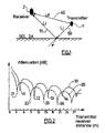
- FIG. 1 illustrates the problem related to the existence of these shadow zones.
- the transmitter 1 transmits an identification signal to the vehicle. Part of the signal transmitted travels the distance Ld indicated by the arrow 40 and reaches the receiver 2 directly. Another part of the signal transmitted indicated by the arrows 50 and 51 reaches the receiver after reflection off obstacles for example the ground 2 A which surround the vehicle. The signal thus reflected is phase shifted with respect to the signal received directly by the receiver 2 . On account of this phase shift, there are localized areas in which the direct incident wave superposed on the reflected wave is not recognized by the receiver 2 . As a consequence, the recognition device does not operate in these localized zones often referred to as “shadow zones”.
- FIG. 1 represents a simplified diagram of the operation of an identification device.
- this diagram is considered the path of a wave 40 which reaches the receiver directly and the path of a wave 50 , 51 which is reflected off the ground 2 A.
- a part of the wave 40 received directly by the receiver 2 has the form:
- a d ⁇ A 2 ⁇ e J2 ⁇ ⁇ ⁇ ⁇ ⁇ L d ⁇ 0 ⁇ A e ⁇
- Ld represents the distance traveled by the transmitted wave between the transmitter 1 and the receiver 2
- ⁇ o is the wavelength of the transmitted wave
- a 2 is dependent on the wavelength and on the distance traveled by the wave.
- This wave 50 , 51 has the form:
- a r ⁇ A 3 ⁇ e J ⁇ [ 2 ⁇ ⁇ ⁇ ( L j + L r ) ⁇ 0 - ⁇ ] ⁇ A e ⁇
- L j represents the distance traveled by the transmitted wave between the transmitter 1 and the ground 2 A
- L r the distance traveled by the transmitted wave between the ground 2 A and the receiver 2
- ⁇ o is the wavelength of the transmitted wave
- a 3 is a function of the wavelength and of the distances traveled by the wave.
- the total wave which arrives at the receiver therefore has the form:
- a t ⁇ [ A 2 ⁇ e J2 ⁇ ⁇ ⁇ ⁇ ⁇ L d ⁇ 0 + A 3 ⁇ e J ⁇ [ 2 ⁇ ⁇ ⁇ ( L j + L r ) ⁇ 0 - ⁇ ] ] ⁇ A e ⁇ .
- This wave varies as a function of the distance between the user and his vehicle and as a function of the frequency of the carrier wave transmitted.
- An aim of the present invention is to provide a reliable identification device despite the phase shift engendered by the reflection of the waves against obstacles.
- the subject of the invention is an identification device intended for controlling the unlocking of openable panels of a vehicle and/or for authorizing the starting of a vehicle comprising a first transmitter which, on command, is able to send a first user identification signal on a carrier of a first given frequency ( ⁇ 1 ) to a receiver, characterized in that it comprises a second transmitter able to transmit at least one second user identification signal on a carrier of a second frequency ( ⁇ 2 ) different from the first frequency in such a way that this second signal can serve as identifying signal in the shadow zones of nonrecognition of the first signal.
- FIG. 1 already described in the preamble represents a simplified diagram of the operation of an identification device known in the art
- FIG. 2 represents for two different frequencies of the carrier a chart of the attenuation of the waves received by the receiver as a function of the distance between the transmitter and the receiver,
- FIG. 3 represents a diagram of “shadow zones” around a vehicle as a function of the wavelength of the carrier signal for two different frequencies of the carrier,
- FIG. 4 represents a first embodiment of a transmitter according to the invention
- FIG. 5 represents a second embodiment of a transmitter according to the invention.
- FIG. 2 is a chart of the attenuation of the waves received by the receiver 2 as a function of the distance between the transmitter 1 and the receiver 2 .
- the curves 10 and 20 represented in this chart are theoretical curves which consider only the superposition of a direct incident wave 40 and of a wave that has been reflected 51 by the ground 2 A (see FIG. 1 ).
- the receiver 2 receives a superposed multitude of waves reflected by various obstacles such as the person who is carrying the receiver, the bodywork of the vehicle, the walls of a building situated nearby, etc.
- the waves reflected by such obstacles have a weaker influence and are therefore neglected in what follows.
- the curve 10 represents the attenuation received by the receiver when the wave transmitted has a given frequency ( ⁇ 1 ).
- the curve 10 of the attenuation of the wave which has a frequency ( ⁇ 1 ) exhibits minima 11 , 12 , 13 at distances of around 4.5, 10.5 and 16 meters.
- a receiver 2 having for example a sensitivity of ⁇ 62 decibel milliwatts (dBm) cannot detect the sending of an identification signal when the user is 9.5 meters or 16 meters away, that is to say at a distance corresponding to the minimum 11 or 12 .
- the identification device will therefore exhibit shadow zones of nonrecognition of the user for these distances.
- the curve 20 of FIG. 2 also represents the attenuation of a wave transmitted at a frequency ( ⁇ 2 ) different from the first frequency ( ⁇ 1 ). In the present example, this is twice the frequency ( ⁇ 1 ). It may be noted that the attenuation curve 20 exhibits minima 21 , 22 , 23 at distances of 3.5, 8.5 and 14 meters and the Applicant has found that the distances for which the wave attenuation phenomenon is observed are different according to the frequency used. The position of the shadow zones of nonrecognition of a user is therefore dependent on the frequency used.
- the Applicant has had the idea of transmitting the identification signal at two different carrier frequencies.
- the shadow zones being linked to the frequency, they therefore appear at different places, doing so as a function of the frequency considered.
- the other frequency is preferably chosen in such a way as to exhibit a field maximum at this same distance.
- the radio range around the vehicle is not altered. As far as the user is concerned, everything occurs as if there were no shadow zones.
- the first frequency ( ⁇ 1 ) is substantially equal to 400 MHz.
- the second frequency is equal to 800 MHz.
- the second frequency ( ⁇ 2 ) is equal to a harmonic of the first frequency ( ⁇ 1 ) and in particular an even harmonic.
- FIG. 3 diagrammatically shows the shadow zones around the vehicle.
- the hatched zones 41 represent the shadow zones of nonrecognition of the signal sent at the frequency ( ⁇ 1 ).
- the surrounded zones 42 represent the shadow zones of nonrecognition of the signal sent at the frequency ( ⁇ 2 ).
- the geographical position of these waves is dependent on the frequency used.
- the first frequency ( ⁇ 1 ) is different from the frequency ( ⁇ 2 )
- these zones do not overlap.
- the receiver recognizes at least one of the two identification signals transmitted.
- the identification device according to the present invention is more reliable.
- the identification device comprises two independent transmitters 30 , 31 cooperating with associated receivers arranged in the vehicle.
- the first transmitter 30 and its associated receiver operate at the frequency ( ⁇ 1 ).
- the second transmitter 31 and its associated receiver operate at the frequency of ( ⁇ 2 ).
- these transmitters 30 , 31 may transmit an identification signal one after the other offset or simultaneously. It is also possible to provide for the second signal to be sent only if the user presses the control button of the transmitter a second time.
- the first and the second transmitter 30 , 31 are formed by a single transmission unit comprising means for toggling from the first to the second frequency and vice versa.
- FIG. 5 represents an exemplary embodiment of a transmitter 1 according to the second embodiment.
- This transmitter consists of a synthesizer 39 linked to an amplifier 33 and an antenna 32 .
- the synthesizer comprises a phase locked loop 36 (PLL) linked to a frequency divider 38 .
- the phase locked loop as well as the frequency divider are both controlled by a microcontroller 37 .
- the use of a synthesizer makes it possible to toggle relatively quickly from a first frequency ( ⁇ 1 ) to a second frequency ( ⁇ 2 ).
- the identification device according to the present invention can also be used in so-called “hands free” devices without operating a remote control box.
Landscapes
- Engineering & Computer Science (AREA)
- Mechanical Engineering (AREA)
- Computer Networks & Wireless Communication (AREA)
- Signal Processing (AREA)
- Lock And Its Accessories (AREA)
Applications Claiming Priority (3)
| Application Number | Priority Date | Filing Date | Title |
|---|---|---|---|
| FR0103484A FR2821961B1 (fr) | 2001-03-12 | 2001-03-12 | Dispositif de reconnaissance destine a commander le deverrouillage d'ouvrants d'un vehicule et/ou autoriser le demarrage d'un vehicule |
| FR01/03484 | 2001-03-12 | ||
| PCT/EP2002/002654 WO2002072987A1 (fr) | 2001-03-12 | 2002-03-11 | Dispositif de reconnaissance pour commander le deverrouillage/demarrage d'un vehicule |
Publications (2)
| Publication Number | Publication Date |
|---|---|
| US20040075341A1 US20040075341A1 (en) | 2004-04-22 |
| US7064457B2 true US7064457B2 (en) | 2006-06-20 |
Family
ID=8861126
Family Applications (1)
| Application Number | Title | Priority Date | Filing Date |
|---|---|---|---|
| US10/471,357 Expired - Fee Related US7064457B2 (en) | 2001-03-12 | 2002-03-11 | Recognition device intended to order the unlocking of a vehicle door and/or to authorize the starting of a vehicle |
Country Status (5)
| Country | Link |
|---|---|
| US (1) | US7064457B2 (fr) |
| EP (1) | EP1387919A1 (fr) |
| JP (1) | JP2004524461A (fr) |
| FR (1) | FR2821961B1 (fr) |
| WO (1) | WO2002072987A1 (fr) |
Cited By (1)
| Publication number | Priority date | Publication date | Assignee | Title |
|---|---|---|---|---|
| DE102009043056A1 (de) * | 2009-09-28 | 2011-03-31 | Marquardt Gmbh | Schließsystem, insbesondere für ein Kraftfahrzeug |
Families Citing this family (4)
| Publication number | Priority date | Publication date | Assignee | Title |
|---|---|---|---|---|
| FR2938991B1 (fr) * | 2008-11-21 | 2012-04-13 | Valeo Securite Habitacle | Systeme de communication pour vehicule automobile. |
| US10008109B2 (en) | 2011-12-09 | 2018-06-26 | Gentex Corporation | System and method for training a programmable transceiver |
| GB2600438A (en) * | 2020-10-29 | 2022-05-04 | Continental Automotive Gmbh | An access device, system and method using cognitive radio |
| FR3132479B1 (fr) * | 2022-02-04 | 2023-12-22 | Continental Automotive Gmbh | Procede d’activation d’une fonction vehicule et dispositif d’activation associe |
Citations (7)
| Publication number | Priority date | Publication date | Assignee | Title |
|---|---|---|---|---|
| GB2119141A (en) | 1982-04-21 | 1983-11-09 | Mastiff Security Syst Ltd | Transmitter token |
| FR2746235A1 (fr) | 1996-03-14 | 1997-09-19 | Siemens Ag | Systeme antivol pour vehicule automobile |
| US5684337A (en) * | 1996-03-08 | 1997-11-04 | Trw Inc. | Keyless vehicle entry receiver having a diagnostic mode of operation wherein a code comparison is not performed |
| DE19732157A1 (de) | 1996-07-26 | 1998-01-29 | Prince Corp | Mehrfachfrequenzsender |
| US5804888A (en) * | 1994-08-26 | 1998-09-08 | Siemens Aktiengesellschaft | Anti-theft system for a motor vehicle |
| US5905431A (en) * | 1993-05-28 | 1999-05-18 | Mueller; Rand W. | Vehicle security system |
| US20040046451A1 (en) * | 2002-08-29 | 2004-03-11 | Kabushiki Kaisha Tokai Rika Denki Seisakusho | Lock control apparatus for use in vehicle |
Family Cites Families (1)
| Publication number | Priority date | Publication date | Assignee | Title |
|---|---|---|---|---|
| JPH09144404A (ja) * | 1995-11-21 | 1997-06-03 | Tokai Rika Co Ltd | 車両用送受信システム、受信機及び送受信システム |
-
2001
- 2001-03-12 FR FR0103484A patent/FR2821961B1/fr not_active Expired - Fee Related
-
2002
- 2002-03-11 EP EP02727395A patent/EP1387919A1/fr not_active Withdrawn
- 2002-03-11 WO PCT/EP2002/002654 patent/WO2002072987A1/fr not_active Application Discontinuation
- 2002-03-11 US US10/471,357 patent/US7064457B2/en not_active Expired - Fee Related
- 2002-03-11 JP JP2002572222A patent/JP2004524461A/ja active Pending
Patent Citations (7)
| Publication number | Priority date | Publication date | Assignee | Title |
|---|---|---|---|---|
| GB2119141A (en) | 1982-04-21 | 1983-11-09 | Mastiff Security Syst Ltd | Transmitter token |
| US5905431A (en) * | 1993-05-28 | 1999-05-18 | Mueller; Rand W. | Vehicle security system |
| US5804888A (en) * | 1994-08-26 | 1998-09-08 | Siemens Aktiengesellschaft | Anti-theft system for a motor vehicle |
| US5684337A (en) * | 1996-03-08 | 1997-11-04 | Trw Inc. | Keyless vehicle entry receiver having a diagnostic mode of operation wherein a code comparison is not performed |
| FR2746235A1 (fr) | 1996-03-14 | 1997-09-19 | Siemens Ag | Systeme antivol pour vehicule automobile |
| DE19732157A1 (de) | 1996-07-26 | 1998-01-29 | Prince Corp | Mehrfachfrequenzsender |
| US20040046451A1 (en) * | 2002-08-29 | 2004-03-11 | Kabushiki Kaisha Tokai Rika Denki Seisakusho | Lock control apparatus for use in vehicle |
Non-Patent Citations (1)
| Title |
|---|
| Patent Abstracts of Japan; publication No. 9-144,404, published on Jun. 3, 1997 (1 page). |
Cited By (1)
| Publication number | Priority date | Publication date | Assignee | Title |
|---|---|---|---|---|
| DE102009043056A1 (de) * | 2009-09-28 | 2011-03-31 | Marquardt Gmbh | Schließsystem, insbesondere für ein Kraftfahrzeug |
Also Published As
| Publication number | Publication date |
|---|---|
| JP2004524461A (ja) | 2004-08-12 |
| FR2821961A1 (fr) | 2002-09-13 |
| US20040075341A1 (en) | 2004-04-22 |
| EP1387919A1 (fr) | 2004-02-11 |
| WO2002072987A1 (fr) | 2002-09-19 |
| FR2821961B1 (fr) | 2007-06-08 |
Similar Documents
| Publication | Publication Date | Title |
|---|---|---|
| US6693581B2 (en) | Device for transmitting data in a motor vehicle | |
| US7986960B2 (en) | Self-aligning vehicular transmitter system | |
| US7155172B2 (en) | RFID receiver apparatus and method | |
| US6049301A (en) | Surveillance apparatus and method for the detection of radio receivers | |
| JP3935432B2 (ja) | オブジェクトへのアクセス又はオブジェクトとりわけ自動車の利用のための権限を証明するための識別システム | |
| US6265988B1 (en) | Apparatus and method for remote convenience message transmission and control utilizing frequency diversity | |
| US6384710B1 (en) | Apparatus and method for remote convenience message reception and control utilizing frequency diversity | |
| KR20020091112A (ko) | 트랜스폰더 및 트랜스폰더 시스템 | |
| US6483425B1 (en) | System for enhancing the security of a bi-directional data transmission system controlling access to an enclosed space, notably a vehicle | |
| US7064457B2 (en) | Recognition device intended to order the unlocking of a vehicle door and/or to authorize the starting of a vehicle | |
| US11926285B2 (en) | Remote communication system | |
| JPH05301561A (ja) | 無線式エンジン始動装置 | |
| GB1605207A (en) | Systems to assist in the location of remote radio transmitters | |
| US6842493B2 (en) | Procedure for increasing the manipulation security for a bi-directional contactless data transmission | |
| JP2006510001A (ja) | 2つの送−受信所の間の距離を求める方法 | |
| JPH09144404A (ja) | 車両用送受信システム、受信機及び送受信システム | |
| US6904101B1 (en) | Tuneless narrow-band super-regenerative receiver | |
| US6445336B2 (en) | Radar device and on-vehicle radar device | |
| US20030085620A1 (en) | Antitheft system, method for operating an antitheft system and components of an antitheft system | |
| US20060097891A1 (en) | Apparatus for sensing tire information, reducing distortion of amplitude-modulated wave | |
| KR20000072891A (ko) | 리모콘신호 송수신장치 | |
| JPH052790B2 (fr) | ||
| KR100479724B1 (ko) | 장파 잡음 회피 회로를 포함하는 무선 도어 잠금 장치 | |
| KR200324586Y1 (ko) | 장파 잡음 회피 회로를 포함하는 무선 도어 잠금 장치 | |
| CN101567706A (zh) | 应答器和应答器系统 |
Legal Events
| Date | Code | Title | Description |
|---|---|---|---|
| AS | Assignment |
Owner name: VALEO ELECTRONIQUE, FRANCE Free format text: ASSIGNMENT OF ASSIGNORS INTEREST;ASSIGNOR:BELINGUIER, THIERRY;REEL/FRAME:014811/0256 Effective date: 20030811 |
|
| REMI | Maintenance fee reminder mailed | ||
| LAPS | Lapse for failure to pay maintenance fees | ||
| STCH | Information on status: patent discontinuation |
Free format text: PATENT EXPIRED DUE TO NONPAYMENT OF MAINTENANCE FEES UNDER 37 CFR 1.362 |
|
| FP | Lapsed due to failure to pay maintenance fee |
Effective date: 20180620 |