US7022185B2 - Apparatus for treating a web of paper or paperboard - Google Patents
Apparatus for treating a web of paper or paperboard Download PDFInfo
- Publication number
- US7022185B2 US7022185B2 US10/472,106 US47210603A US7022185B2 US 7022185 B2 US7022185 B2 US 7022185B2 US 47210603 A US47210603 A US 47210603A US 7022185 B2 US7022185 B2 US 7022185B2
- Authority
- US
- United States
- Prior art keywords
- web
- chamber
- application
- suction
- application chamber
- Prior art date
- Legal status (The legal status is an assumption and is not a legal conclusion. Google has not performed a legal analysis and makes no representation as to the accuracy of the status listed.)
- Expired - Fee Related
Links
Images


Classifications
-
- B—PERFORMING OPERATIONS; TRANSPORTING
- B05—SPRAYING OR ATOMISING IN GENERAL; APPLYING FLUENT MATERIALS TO SURFACES, IN GENERAL
- B05B—SPRAYING APPARATUS; ATOMISING APPARATUS; NOZZLES
- B05B13/00—Machines or plants for applying liquids or other fluent materials to surfaces of objects or other work by spraying, not covered by groups B05B1/00 - B05B11/00
- B05B13/02—Means for supporting work; Arrangement or mounting of spray heads; Adaptation or arrangement of means for feeding work
- B05B13/0207—Means for supporting work; Arrangement or mounting of spray heads; Adaptation or arrangement of means for feeding work the work being an elongated body, e.g. wire or pipe
-
- B—PERFORMING OPERATIONS; TRANSPORTING
- B05—SPRAYING OR ATOMISING IN GENERAL; APPLYING FLUENT MATERIALS TO SURFACES, IN GENERAL
- B05B—SPRAYING APPARATUS; ATOMISING APPARATUS; NOZZLES
- B05B12/00—Arrangements for controlling delivery; Arrangements for controlling the spray area
- B05B12/16—Arrangements for controlling delivery; Arrangements for controlling the spray area for controlling the spray area
- B05B12/18—Arrangements for controlling delivery; Arrangements for controlling the spray area for controlling the spray area using fluids, e.g. gas streams
-
- B—PERFORMING OPERATIONS; TRANSPORTING
- B05—SPRAYING OR ATOMISING IN GENERAL; APPLYING FLUENT MATERIALS TO SURFACES, IN GENERAL
- B05B—SPRAYING APPARATUS; ATOMISING APPARATUS; NOZZLES
- B05B14/00—Arrangements for collecting, re-using or eliminating excess spraying material
- B05B14/30—Arrangements for collecting, re-using or eliminating excess spraying material comprising enclosures close to, or in contact with, the object to be sprayed and surrounding or confining the discharged spray or jet but not the object to be sprayed
-
- B—PERFORMING OPERATIONS; TRANSPORTING
- B05—SPRAYING OR ATOMISING IN GENERAL; APPLYING FLUENT MATERIALS TO SURFACES, IN GENERAL
- B05B—SPRAYING APPARATUS; ATOMISING APPARATUS; NOZZLES
- B05B15/00—Details of spraying plant or spraying apparatus not otherwise provided for; Accessories
- B05B15/50—Arrangements for cleaning; Arrangements for preventing deposits, drying-out or blockage; Arrangements for detecting improper discharge caused by the presence of foreign matter
- B05B15/55—Arrangements for cleaning; Arrangements for preventing deposits, drying-out or blockage; Arrangements for detecting improper discharge caused by the presence of foreign matter using cleaning fluids
- B05B15/555—Arrangements for cleaning; Arrangements for preventing deposits, drying-out or blockage; Arrangements for detecting improper discharge caused by the presence of foreign matter using cleaning fluids discharged by cleaning nozzles
-
- D—TEXTILES; PAPER
- D21—PAPER-MAKING; PRODUCTION OF CELLULOSE
- D21H—PULP COMPOSITIONS; PREPARATION THEREOF NOT COVERED BY SUBCLASSES D21C OR D21D; IMPREGNATING OR COATING OF PAPER; TREATMENT OF FINISHED PAPER NOT COVERED BY CLASS B31 OR SUBCLASS D21G; PAPER NOT OTHERWISE PROVIDED FOR
- D21H23/00—Processes or apparatus for adding material to the pulp or to the paper
- D21H23/02—Processes or apparatus for adding material to the pulp or to the paper characterised by the manner in which substances are added
- D21H23/22—Addition to the formed paper
- D21H23/50—Spraying or projecting
-
- D—TEXTILES; PAPER
- D21—PAPER-MAKING; PRODUCTION OF CELLULOSE
- D21H—PULP COMPOSITIONS; PREPARATION THEREOF NOT COVERED BY SUBCLASSES D21C OR D21D; IMPREGNATING OR COATING OF PAPER; TREATMENT OF FINISHED PAPER NOT COVERED BY CLASS B31 OR SUBCLASS D21G; PAPER NOT OTHERWISE PROVIDED FOR
- D21H23/00—Processes or apparatus for adding material to the pulp or to the paper
- D21H23/78—Controlling or regulating not limited to any particular process or apparatus
-
- D—TEXTILES; PAPER
- D21—PAPER-MAKING; PRODUCTION OF CELLULOSE
- D21H—PULP COMPOSITIONS; PREPARATION THEREOF NOT COVERED BY SUBCLASSES D21C OR D21D; IMPREGNATING OR COATING OF PAPER; TREATMENT OF FINISHED PAPER NOT COVERED BY CLASS B31 OR SUBCLASS D21G; PAPER NOT OTHERWISE PROVIDED FOR
- D21H25/00—After-treatment of paper not provided for in groups D21H17/00 - D21H23/00
- D21H25/08—Rearranging applied substances, e.g. metering, smoothing; Removing excess material
- D21H25/16—Rearranging applied substances, e.g. metering, smoothing; Removing excess material with a blast of vapour or gas, e.g. air knife
-
- Y—GENERAL TAGGING OF NEW TECHNOLOGICAL DEVELOPMENTS; GENERAL TAGGING OF CROSS-SECTIONAL TECHNOLOGIES SPANNING OVER SEVERAL SECTIONS OF THE IPC; TECHNICAL SUBJECTS COVERED BY FORMER USPC CROSS-REFERENCE ART COLLECTIONS [XRACs] AND DIGESTS
- Y02—TECHNOLOGIES OR APPLICATIONS FOR MITIGATION OR ADAPTATION AGAINST CLIMATE CHANGE
- Y02P—CLIMATE CHANGE MITIGATION TECHNOLOGIES IN THE PRODUCTION OR PROCESSING OF GOODS
- Y02P70/00—Climate change mitigation technologies in the production process for final industrial or consumer products
- Y02P70/10—Greenhouse gas [GHG] capture, material saving, heat recovery or other energy efficient measures, e.g. motor control, characterised by manufacturing processes, e.g. for rolling metal or metal working
Definitions
- the invention relates to an apparatus for applying a web treatment substance to the surface of a moving web of paper or paperboard by means of spray nozzles.
- One promising application method is the spray-coating technique, wherein the coating furnish or other web treatment material is applied to the surface of a paper or paperboard web by means of high-pressure spray nozzles.
- the web treatment material is pressurized to a high pressure and then sprayed from a small-orifice spray nozzle at a high velocity onto the web.
- a benefit of the method is that it imposes minimal stress on the web resulting in a good runnability behavior of the spray-coating apparatuses.
- this kind of application excels over conventional blade and film-transfer techniques by being more gentle and less stressing to the web thus facilitating a production efficiency increase of about 5% as compared with blade application.
- this allows the web to be produced from a stock of weaker strength, which is a particular benefit in making paper from recycle fiber.
- Contacting application methods such as blade coating or film-transfer coating always need between the web surface and the excess-coating-doctoring element a gap that determines the thickness of the applied coat. Due to this and other factors, the final coat weight is affected by quality variations in the base sheet, among other things by its profile deviations and surface roughness.
- a spray-coater applies to the web under all circumstances a coating layer of constant weight entirely unaffected by base sheet quality variations.
- spray-coating can be performed to a base sheet whose moisture content is higher and, hence, whose strength is lower than what has been acceptable earlier.
- the coating mixture, surface size or other web treatment substance is applied in the spray-coating technique to the web surface in the form of a droplet shower that flies in a free space the travel from the nozzle tip to the web being treated, a practicable implementation of the system is complicated by the tendency of the coating mist to escape to the surrounding atmosphere. Therefore, the spray nozzles must be enclosed by a hood. In the hood the coating mixture mist condenses on all surfaces wherefrom it must be recovered so that large drops of the condensate are stopped from reaching the web surface. Furthermore, the condensed coating mixture must be prevented from access to the coating spray.
- assemblies for collecting aerosol mists are known from, e.g., the art of spray-painting arrangements. Since these assemblies are designed, however, for handling unit articles, they permit paint application to be carried out in an entirely closed space or, alternatively, the materials to be treated are so durable and travel at such a slow speed that the space of active treatment of articles can be readily isolated from the surrounding space.
- These painting or, more broadly, surface treatment systems are used for surface treatment of sheet metal, for instance.
- the web speeds today used in papermaking machines are so high that the air boundary layer traveling along with the web has grown to be an extremely powerful factor of disturbance.
- the trend is to run as thin base webs as possible made from low-strength fiber in order to cut down the product price. This results in a conflicting situation, wherein the flow of the air boundary layer at the critical areas of the web surface needs to be prevented by effective means but, however, the moving web itself cannot take a robust mechanical contact, for instance.
- the goal of the invention is achieved by way of dividing the coater apparatus into at least two chambers which are separated from the surrounding environment so that one of the chambers is adapted to face the surface of the moving web being treated while the other chamber is located on the opposite side of the web, whereby the pressures in these chambers are adjusted so that the pressure in the chamber closest to the web surface being treated is lower than the ambient pressure and the pressure in the chamber located behind the application chamber as seen from the direction of the web is lower than the pressure in the application chamber.
- the coating mist formed in the interior of the application chamber, as well as the excess flowable web treatment substance are removed from the application chamber via one and the same path.
- the invention offers significant benefits.
- the invention makes it possible to control the flow of a fluid web treatment substance, the mist generated therefrom and air flows in an application chamber so that there is no risk of the deterioration of the coated or otherwise treated web surface or of the coating mist escaping to the surrounding environment. All the material components existing in the different phases of state in the application chamber are collected away via one and the same path thus making the handling of the different material components effective.
- the mist of web treatment substance is separated from the air removed by suction from the application chamber and is recirculated, together with the curtain flow of the substance collected from the walls of the chamber, back to the circulation of the web treatment substance.
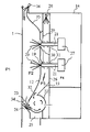
- FIG. 1 shows a coater arrangement utilizing a spray-coater assembly according to the invention
- FIG. 2 shows a first embodiment of the invention
- FIG. 3 shows a second embodiment of the invention
- FIG. 4 shows the assembly of FIG. 3 in its inverted operating position
- FIG. 5 shows the assembly of FIG. 3 and a first embodiment of a washing system adapted to cooperate therewith;
- FIG. 6 shows the assembly of FIG. 3 and a second embodiment of a washing system adapted to cooperate therewith;
- FIG. 7 shows the assembly of FIG. 3 and a third embodiment of a washing system adapted to cooperate therewith.
- FIG. 1 therein is shown a coater arrangement suited for utilizing an assembly according to the invention for applying a web treatment substance to the surface of a moving web.
- the invention may be readily adapted to a plurality of treatment systems, whereby the present exemplary embodiment only serves to elucidate a typical application environment of the invention.
- a spray-coater is arranged to operate in conjunction with a dryer cylinder group, wherein a web 1 passes over cylinders 2 so that the side of the web facing a dryer cylinder 2 changes in an alternating fashion.
- the arrangement shown in FIG. 1 may be considered to illustrate a portion of a dryer cylinder group or even the entire group.
- the assembly can be implemented by locating the applicator units at any point of the cylinder group assembly. Obviously, the number of cylinders needed herein is dependent on the required drying capacity.
- the web 1 is passed onto the first cylinder 2 , and a spray-coater unit 7 is adapted to operate in conjunction with the next cylinder 9 .
- the coater unit 7 comprises a hood 5 with spray nozzles 6 located therein.
- Application takes place by feeding a web treatment substance at a high pressure, e.g., about 80 to 180 bar, into spray nozzles 6 , whereby the treatment agent at exit from a nozzle of a small diameter of about 0.25 to 0.4 mm attains a velocity of about 100 m/s, is atomized into droplets and spreads as a fan-shaped spray of a given opening angle determined by the design of the spray nozzle.
- the fine-atomized coating mist hits the surface of the passing web.
- the nozzles may be placed over the cross-machine width of the web at 50 to 70 mm distance between each other into a single linear array or plural arrays, and the distance of the nozzles from the web is typically 10 to 100 mm.
- an ion-blast unit 3 comprising a plurality of pointed electrodes 8 .
- a high-voltage field can be applied between the electrodes 8 and the cylinder 9 , whereby the stream of ionized gas molecules leaving the electrode tips also ionizes the coating mist 4 possibly trying to escape from the hood 5 and then, with the help of the electric field, directs the mist to adhere to the surface of the web 1 .
- This device serving to capture the stray coating mist may be constructed integral with the coater unit or, alternatively, be a separate device.
- the mist control device is located as close as possible to the coater unit 7 .
- a coating mist control method and device based on the ion-blast technique is described in the applicant's European patent application EP 1 040 225.
- the web 1 passes to the next cylinder 10 , whereby the outside of the web not facing the cylinder is reversed.
- This cylinder incorporates similar coater and coating mist control means as those described above for treating the other side of the web.
- the web 1 passes over two dryer cylinders to the next application phase, wherein application takes place in the same fashion as in the first application phase.
- This embodiment is characterized in that a noncontacting dryer is not used for drying the coated side of the web after application, which means that the weight and quality of the applied coat must be selected such that the coating will dry and set sufficiently before the treated side of the web meets the dryer cylinder. Accordingly, this configuration is best suited for applying lightweight coats.
- a coater according to the invention is shown operating about a web 1 .
- the assembly is located in the interior of a hood 11 that isolates the components of the assembly from the surroundings.
- the open side of the hood 11 faces the moving web 1 .
- the web 1 is arranged to run vertically. This orientation of web run is the easiest way to prevent the condensation of coating mist into drops in the free interior space of the hood and to collect the stray mist in the application chamber, together with the web treatment substance condensed from the mist onto the interior walls of the application chamber, so that none of the treatment substance in either fluid or large-drop condensate can reach the web.
- the hood 11 delineates three mutually communicating chambers P 2 , P 3 and P 4 .
- the area on the opposite side of the web 1 relative to the coater apparatus is marked as space P 1 that denotes the surroundings of the coater apparatus. The roles of these spaces will be discussed in more detail later in the text.
- Chamber P 2 is principally delineated by the web 1 and a flow guide baffle 12 . Later in the text this space is called the application chamber.
- the top edge of the flow guide baffle 12 is provided with a pressurized-air duct 13 , whose external wall 14 facing the web 1 is inclined so as to reach close to the web 1 .
- a plurality of air jets are ejected from the pressurized-air duct 13 .
- An air jet slot 18 is adapted to the portion of the duct closest to the web, whereby the air jet ejected therefrom is impinged directly on the web 1 . This air jet is arranged to support the web 1 or to prevent the entry of air traveling along with the web into the application chamber P 2 .
- the ventilation air of the application chamber is provided by another air jet directed from nozzles 17 downward obliquely into the interior of the application chamber P 2 and by another air jet directed parallel with the travel of the web 1 from nozzles 16 adapted to operate in the vicinity of the upper end of the flow guide baffle 12 .
- the function of these air jets is to border the spray mist volume saturated by the sprays of the web treatment substance to stay below the linear array of spray nozzles so that the mist cannot escape via the gap remaining between the web 1 and the coater apparatus and that accumulation of the web treatment substance on structures above the linear array of spray nozzles is prevented.
- a further function of the air jets and, in particular, of the jets directed from nozzles 6 is to prevent detrimental turbulence that otherwise would be invoked in the interior of the application chamber P 2 by the linear movement of the web.
- the pressurized-air duct 13 receives supplementary air via openings 15 , whereby the inflow of the supplementary air also reduces the amount of air entering along with the web.
- the top edge of the flow guide baffle 12 is located immediately below the pressurized-air duct and nozzles 16 .
- on the flow guide baffle are made two horizontal rows of openings to provide through holes 19 for spray nozzles 21 .
- the flow guide baffle 12 is bent backward behind the tip of nozzles 21 just above the nozzles 21 , while the lower edge of the through hole below the nozzles 21 is aligned flush with the principal plane of the flow guide baffle 12 .
- the bent portion of the baffle extends 5 to 10 mm behind the principal plane of the flow guide baffle.
- the flow guide baffle 12 is bent toward the web 1 so that the baffle ends at an inlet opening 23 of a suction channel 22 .
- the suction channel 22 and the suction opening 23 extend over the entire cross-machine width of the coater apparatus.
- a gas knife 24 At the lower edge of the suction opening 23 is adapted to operate a gas knife 24 in which a flow of air is provided from a pressurized-air chamber 25 located therebelow.
- the coater apparatus comprises two superposed nozzle array beams 27 , each having a linear nozzle array mounted thereon.
- a suction chamber P 3 Between the flow guide baffle 12 and the partition 26 is formed a suction chamber P 3 , wherein the pressure is kept below that of application chamber P 2 and spray nozzle beam chamber P 4 .
- the upper portion of the suction chamber P 3 is provided with one or more nozzles 28 for spraying a substance that removes accumulations possibly deposited in the suction chamber P 3 and a suction duct 22 located in the lower portion thereof.
- This flushing substance may be, e.g., water, a suitable chemical or the web treatment substance, surface size or a mixture thereof.
- the choice of a suitable flushing substance is primarily dictated by the type of web treatment substance used in the process. For instance, when calcium carbonate-based coating finishes are used, the accumulations on the structures of the assembly are advantageously removed by means of a diluted acid, such as citric acid for instance.
- the acid disintegrates calcium carbonate into calcium and carbon dioxide.
- the suction chamber P 3 also includes means 29 , 30 for cooling those surfaces that are situated above the level of the spray nozzle arrays penetrating the flow guide baffle 12 . Cooling may be implemented with the help of channels filled with a cooling liquid.
- the coater apparatus forms in a close vicinity of web 1 a spray-coating zone delineated by the flow guide baffle 12 , the moving web 1 and, on the ingoing side of the web, by the air jets ejected from the nozzles 18 and, on the outgoing side, by a gas jet knife 24 .
- the web 1 is subjected within the above-defined spraying zone to a spray-coating step applied from nozzles 21 that eject an atomized spray of a web treatment substance which may be, e.g., a coating furnish, surface size or other treatment substance such as a polymeric coating or even simply water used for wetting the web.
- a plurality of spray nozzles 21 are located to operate over the cross-machine width of the web and their spray patterns on the web may be discrete or partially overlapping. While the embodiment of FIG. 2 is drawn to have two linear arrays of nozzles operating in succession, it is obvious that the number of nozzle arrays may be varied as considered appropriate. The benefit of using two or more nozzle arrays is that they can be used alternatively when so required due to washing or servicing, for instance.
- the top region of the spray-coating zone is delineated by an air jet released from the pressurized-air duct via nozzles 18 so as to simultaneously support the web. From the same duct is also ejected air via nozzles 16 , 17 in order to ventilate the spray-coating zone.
- the function of the air jets is to border the spray mist space filled by the sprays 20 of the web treatment substance to stay below the linear array of spray nozzles so that accumulation of the web treatment substance on structures above the upper linear array of spray nozzles is prevented.
- a further particular function of the air jets ejected from nozzles 16 is to prevent detrimental turbulence that otherwise would be invoked in the interior of the application chamber by the linear movement of web 1 . If the substance being applied is allowed to condense, it can readily form dripping accumulations that, when falling into the spray of the web treatment substance, land on the web 1 thus causing defects in the applied coating.
- the portions of the flow guide baffle 12 situated above the linear nozzle arrays are cooled down to a temperature below the dew point of the atmosphere prevailing in the application chamber.
- a film of the web treatment substance that flows downward along the surface of the flow guide baffle.
- the flowing film of fluid treatment substance traps the stray mist thus preventing the web treatment substance from drying or solidifying on the surface of the baffle.
- the top edges of the through holes 19 of nozzles 21 are bent inward toward suction chamber P 3 .
- the flow guide baffle 12 As the web treatment substance condensate flows downward along the surface of the flow guide baffle 12 , the flow follows to the curved edge of the opening thus forcing the flow to proceed behind the tip of nozzle 21 protruding via the nozzle through hole 19 , whereby the fluid condensate of the web treatment substance cannot fall into the spray of the web treatment substance.
- the pressure in the suction chamber P 3 is maintained below that of application chamber P 2 thus inducing a flow at the nozzle through holes 19 from application chamber P 2 to suction chamber P 3 .
- the flow rate at this point must be sufficiently high to prevent the ejector effect of web treatment substance spray 20 from sucking the dripping condensate back into the application chamber and its application spray so as to allow it fall in detrimental drops onto the web 1 .
- a sufficiently high flow rate can be secured by applying a reasonably high differential pressure between the chambers and securing a sufficiently high discharge flow rate of air from the suction chamber.
- the suction flow via the nozzle through holes directs both the condensate formed on the tip of the nozzle as well as the condensate flowing downward from above to be collected into suction chamber P 3 .
- the pressure of suction chamber P 3 is maintained lower than that of the spray nozzle beam chamber P 4 , stray mist of web treatment substance is prevented from entering the spray nozzle beam chamber P 4 and the interior parts of the coater.
- Suction duct 22 is used for applying a vacuum to suction chamber P 3 and for collecting away the fluid phase of the web treatment substance and the mist thereof entrained with the air sucked into the duct.
- the pressure in the suction duct must be kept so low in regard to the ambient pressure that the flows entering the duct 22 of a circular cross section are really vigorous.
- the vacuum system of the coater apparatus comprises a suction fan connected to the suction duct 22 so that the duct is evacuated from air by means of a suction fan.
- the duct 22 is adapted to communicate via opening 32 with suction chamber P 3 , also this chamber is kept under a vacuum. Since the suction duct 22 is further adapted to communicate with application chamber P 2 via a suction inlet opening 23 , also the application chamber can be kept under a vacuum by means of the suction duct 22 .
- the lower portion of flow guide baffle 12 is bent toward the moving web 1 thus locating the suction inlet opening 23 in a close vicinity of the web.
- the suction inlet opening 23 is shaped so that it directs the inlet flow tangentially with the interior wall of the suction duct 22 having a circular cross section.
- another inlet channel 32 entering into the suction chamber P 3 is adapted substantially tangentially thereto, whereby its one side is formed by the rear wall of the flow guide baffle 12 .
- the other wall of the inlet channel is formed by a flow channel wall 33 .
- the flow channel wall together with the rear wall of the flow guide baffle 12 give the inlet channel a tapering cross section.
- a highly characterizing feature of the present invention is the division of the coater apparatus construction into at least two, advantageously three chambers P 2 , P 3 and P 4 that are isolated from the ambient pressure of the surrounding space P 1 .
- the pressure of application chamber P 2 must be kept lower than the pressure of the surrounding space P 1 and higher than pressure of suction chamber P 3 in order to prevent the web treatment substance from escaping to the surroundings and thereby to collect stray mist and condensed fluids accumulated in the application chamber.
- the pressure in the spray nozzle beam chamber P 4 is kept above that of the suction chamber P 3 to prevent stray mist of the web treatment substance from entering into the interior space the coater apparatus.
- paper web 1 tends to catch the mist of web treatment substance together with air along with its travel. This aerosol may not be allowed to escape from application chamber P 2 .
- the outgoing side of web 1 is sealed by a gas-jet knife 24 which is located at the outgoing end of the coater and is adapted to communicate with the pressurized-air chamber 25 .
- the gas generally air; blown out from the slit nozzle of the gas jet knife 24 effectively prevents the aerosol mist from escaping to the surroundings.
- a blower or compressor may be used for establishing the required pressure in the pressurized-air chamber 25 so that the pressure level therein is typically 100 to 6000 Pa above the ambient pressure.
- To above the gas jet knife 24 is placed a flow guide 34 that divides into two channels the suction inlet opening 23 of suction inlet 22 as far as its reaches into the application chamber P 2 .
- the function of the flow guide 34 is to prevent the downward falling web treatment substance drops and mist from reaching the gas jet knife, particularly along with the flow passing via the gap between gas jet knife 24 and flow guide 34 . If accumulation of liquid material on the top surface of the gas jet knife 24 should occur, the rapid air flow discharged from the narrow slit of the gas jet knife, which typically is 0.1 to 2 mm wide, would splash the liquid as detrimental drops onto the web 1 .
- the flow guide 34 is cooled down to a temperature below the dew point in this space so that no residues of the web treatment substance can remain drying on the surfaces of the flow guide.
- cooling is implemented, e.g., by making the flow guide 34 hollow and then providing a cooling liquid channel therein.
- the air jets at the upper portion of the application zone have been made unnecessary by a suitable contouring of the flow guide baffle 35 .
- the flow guide baffle 35 is located close to the web at the ingoing end of the web 1 and is then contoured to bend away from web 1 so as to form the application chamber.
- the air boundary layer traveling along with the entering web causes a strong air flow in the gap between web 1 and flow guide baffle 35 . This vigorous air flow prevents the mist of web treatment substance from escaping to the surroundings from the application chamber via the ingoing side of the web 1 .
- the backward-bent shape of the flow guide baffle 35 allows the cross section of the entering air flow to increase rapidly, whereby the pressure and flow velocity of the air flow fall. Resultingly, the turbulence of the entering air dies off and the flow cannot reach at full power the sprays 20 of the web treatment substance.
- a nozzle or nozzles 36 for blowing moist air or steam into entry gap of the web in order to moisten the air entering the application chamber and to improve condensation on the cooled surfaces of the chamber.
- the cooled area 29 above the uppermost linear nozzle array is shown extending only slightly above the nozzle array in the same fashion as in the embodiment of FIG. 2 .
- the cooled area may be extended further, even up to the ingoing-side edge of the flow guide baffle 35 .
- the assembly described above is similar to that shown in FIG. 2 .
- FIG. 4 is shown an embodiment suited for treating a web running vertically upwards.
- the suction duct 22 is located at the upper part of the assembly, but otherwise the basic construction and function of the coater apparatus are identical to those described in the foregoing.
- the web ingoing side of the coater apparatus must be provided with a second suction duct 37 for collecting liquid accumulations and drippings.
- the suction duct at the outgoing side of the assembly opens only toward the application chamber P 2 , whereby the duct serves for collecting stray mist alone.
- the vacuum of suction chamber P 3 is applied via the ingoing-side of suction duct 37 .
- FIG. 5 is shown a washing arrangement for cleaning the nozzles.
- the spray nozzle beam chamber P 4 is provided for each one of the linear nozzle arrays with separate washing chambers 38 into which the ends of the nozzles 21 can be inserted.
- the washing chambers 38 incorporate washing nozzles 39 for spraying a washing liquid against the end of the nozzle 21 and a drainage line 40 for removal of spent washing liquid.
- Either one of the nozzle array beams 27 has its own washing chamber 38 wherein the entire nozzle array is washed in a single step.
- the washing nozzle 39 may be arranged to move in parallel with the nozzle array and treat one nozzle at a time or, alternatively, a separate washing nozzle may be provided for each one of the web treatment substance nozzles of the array.
- the through holes 19 of the flow guide baffle 12 and the openings 31 of the partition are equipped with blind flaps 41 , 42 that prevent any flow through the openings when the nozzle array beam 27 and the spray nozzles 21 are taken into their washing position.
- FIG. 6 is implemented using a dual-sided nozzle array beam 43 , wherein the spray nozzles 21 for spraying the web treatment substance are aligned in opposite directions.
- the arrangement makes it possible to run the apparatus in a continuous fashion even during washing.
- FIG. 7 uses a four-beam system 44 of spray nozzles.
- the nozzle beam assembly shown therein comprises four nozzle arrays of which one is always in the application position, two in the washing position and one in the service position, wherein repair operations such as nozzle replacement, for instance, can be carried out.
- This embodiment allows fast change-over of nozzle arrays into a different position and eliminates interruptions due to washing or service operations performed on a nozzle array.
- the construction also permits the use of different sizes of nozzles in the different nozzle arrays thus facilitating rapid change-over of paper grade in production.
- the web 1 is adapted to run vertically upward or downward.
- the coater apparatus can be adapted in any position provided that the web is at all times arranged to run above the coater, either vertically or in any slanted position.
- the web In systems used for simultaneous two-sided application, the web must be arranged to run in a vertical direction.
- the condensate of the web treatment substance is prevented from landing on the web.
- the number of nozzle arrays and nozzle array beams may be varied from those of the exemplary embodiments.
- a single nozzle beam assembly may comprise, e.g., three linear nozzle arrays and the number of linear nozzle arrays in a coater apparatus can be made as large as permitted by the available space.
- the nozzles are advantageously manipulated as contiguous linear array assemblies, whereby their transfer between the washing, servicing and operative positions and handling in these positions is most uncomplicated. Obviously, individual handling of nozzles could be contemplated, but this alternative readily complicates the construction of the apparatus.
- a falling film is formed on the flow guide baffle from the condensing mist. If certain web treatment substances or given operating conditions do not generate a sufficient amount of mist for forming a condensate, the falling film can be established by means of nozzles or a narrow slit adapted to operate at the upper edge of the flow guide baffle. Obviously, the falling film may be generated from some other substance than the web treatment substance currently being used.
- the air flow vortex is easiest to induce in a duct of circular cross section and, furthermore, this kind of duct has no corners where dry web treatment substance could accumulate.
- the upper lip of the gas jet knife that seals the application chamber at the outgoing side of the web can be shaped to reach toward the web, finally bending parallel with the web, whereby the air flow induced by the gas jet knife follows the curved shape up to the tip of the gas jet knife thus keeping the gas jet knife free from soiling.
Applications Claiming Priority (5)
| Application Number | Priority Date | Filing Date | Title |
|---|---|---|---|
| FI20010504 | 2001-03-13 | ||
| FI20010504A FI115314B (fi) | 2001-03-13 | 2001-03-13 | Sovitelma paperin tai kartongin käsittelemiseksi |
| PCT/FI2002/000203 WO2002072953A1 (en) | 2001-03-13 | 2002-03-13 | Assembly for treating a web of paper or paperboard |
| FI20020562A FI111912B (fi) | 2001-03-13 | 2002-03-22 | Menetelmät spraypäällystysaseman ohjaamiseksi |
| DE10330801A DE10330801A1 (de) | 2001-03-13 | 2003-07-08 | Verfahren zum Steuern einer Strahlbeschichtungs-Anlage |
Publications (2)
| Publication Number | Publication Date |
|---|---|
| US20040074440A1 US20040074440A1 (en) | 2004-04-22 |
| US7022185B2 true US7022185B2 (en) | 2006-04-04 |
Family
ID=57286938
Family Applications (1)
| Application Number | Title | Priority Date | Filing Date |
|---|---|---|---|
| US10/472,106 Expired - Fee Related US7022185B2 (en) | 2001-03-13 | 2002-03-13 | Apparatus for treating a web of paper or paperboard |
Country Status (8)
| Country | Link |
|---|---|
| US (1) | US7022185B2 (fi) |
| EP (1) | EP1383961B1 (fi) |
| JP (2) | JP3946642B2 (fi) |
| CN (1) | CN1263925C (fi) |
| CA (1) | CA2440300A1 (fi) |
| DE (2) | DE60223666T2 (fi) |
| FI (2) | FI115314B (fi) |
| WO (1) | WO2002072953A1 (fi) |
Cited By (6)
| Publication number | Priority date | Publication date | Assignee | Title |
|---|---|---|---|---|
| US20070051141A1 (en) * | 2005-09-03 | 2007-03-08 | Fleissner Gmbh | Suction apparatus for a fabric-treatment water-jet beam |
| US20080011439A1 (en) * | 2006-06-30 | 2008-01-17 | Fleissner Gmbh | Suction apparatus for textile-treatment water-jet beam |
| US20110078883A1 (en) * | 2006-12-04 | 2011-04-07 | Fleissner Gmbh | Suction chamber for a water bar used for applying jets to fabrics |
| US20120111516A1 (en) * | 2010-04-29 | 2012-05-10 | Metso Paper, Inc. | Method and Apparatus for Treating a Fibrous Web |
| US20120138249A1 (en) * | 2010-12-02 | 2012-06-07 | Patrick Sundholm | Method for improving paper and board's resistance to the penetration of liquids |
| DE102014100651A1 (de) * | 2014-01-21 | 2015-07-23 | Paperchine Gmbh | Luftdichtungsvorrichtung für einen Sprühapparat in einer Papierherstellungsmaschine |
Families Citing this family (28)
| Publication number | Priority date | Publication date | Assignee | Title |
|---|---|---|---|---|
| ATE463620T1 (de) * | 2001-05-23 | 2010-04-15 | Voith Patent Gmbh | Auftragsvorrichtung |
| FI6176U1 (fi) | 2003-10-28 | 2004-03-25 | Metso Paper Inc | Spraypäällystysyksikkö |
| SE526978C2 (sv) | 2004-04-20 | 2005-11-29 | Metso Paper Karlstad Ab | Skyddsanordning för sprayutrustning och sätt att skydda denna och dess omgivning |
| US20080029234A1 (en) * | 2004-07-30 | 2008-02-07 | Metso Automation Oy | Method Of Moistening Paper Web And Paper Web Moistening Device |
| FI123458B (fi) * | 2006-08-24 | 2013-05-15 | Stora Enso Oyj | Menetelmä paperi- tai kartonkituotteen päällystämiseksi ja näin saatu tuote |
| JP4754454B2 (ja) * | 2006-10-10 | 2011-08-24 | 東洋ガラス株式会社 | ガラスびん口部天面のコーティング方法 |
| FI124251B (fi) * | 2007-05-14 | 2014-05-15 | Valmet Technologies Inc | Menetelmä ja sovitelma kuituradan käsittelemiseksi |
| EP2230005A1 (de) * | 2009-03-19 | 2010-09-22 | Sika Technology AG | Betriebssichere Beschichtungsvorrichtung für pulverförmiges Material |
| JP5241748B2 (ja) * | 2010-02-02 | 2013-07-17 | 信栄製紙株式会社 | ウエブへ薬剤を噴霧する噴霧装置、ウエブへ薬剤を噴霧する噴霧方法 |
| FI20105915A0 (fi) | 2010-08-31 | 2010-08-31 | Metso Paper Inc | Menetelmä ja laitteisto kuiturainan käsittelemiseksi |
| DE102011002671A1 (de) * | 2011-01-13 | 2012-07-19 | Metso Paper, Inc. | Leimmittelzuführsystem zum Zuführen von Leimmittel zu einer Papier- oder Kartonbahn |
| EP2647760B1 (en) | 2012-04-02 | 2017-12-27 | Valmet Technologies, Inc. | Device for treating a fiber web |
| ITTO20120981A1 (it) * | 2012-11-13 | 2014-05-14 | Itt Italia Srl | Metodo ed impianto per la verniciatura a polvere di elementi elettricamente non conduttivi, in particolare pastiglie freno |
| EP2735648A1 (en) * | 2012-11-22 | 2014-05-28 | Valmet Technologies, Inc. | Device for treating a fiber web |
| EP2784217A1 (en) | 2013-03-27 | 2014-10-01 | Valmet Technologies, Inc. | Arrangement in a fiber web production line and method in a fiber web production line |
| US20140319241A1 (en) * | 2013-04-30 | 2014-10-30 | Armstrong World Industries, Inc. | System and method for humidifying a system for applying a coating to a workpiece |
| EP2808087B1 (en) | 2013-05-28 | 2019-02-27 | Valmet Technologies, Inc. | Device for treating a fibre web |
| EP2860312B1 (en) | 2013-10-08 | 2019-05-22 | Valmet Technologies, Inc. | Arrangement of a fiber web production line and method of a fiber web production line |
| EP2868802A1 (en) | 2013-10-31 | 2015-05-06 | Valmet Technologies, Inc. | Arrangement of a fiber web production line and method of a fiber web production line |
| EP2985385A1 (en) * | 2014-08-11 | 2016-02-17 | Xavier Blanch Andreu | Spraying device for spraying a liquid product onto paper sheet |
| CN104928959B (zh) * | 2015-03-23 | 2017-01-25 | 济南大学 | 一种无转子的空气涡旋制浆设备 |
| DE102017107213A1 (de) * | 2017-04-04 | 2018-10-04 | Andritz Küsters Gmbh | Verfahren und Vorrichtung zur Aufbringung eines Stoffs auf eine sich bewegende Bahn |
| CN110997158A (zh) * | 2017-08-02 | 2020-04-10 | 福伊特专利有限公司 | 用于对料幅进行涂层的方法 |
| US11185879B2 (en) * | 2018-02-08 | 2021-11-30 | Nordson Corporation | Systems and methods for calibrating flow and for coating a substrate |
| CN112902356B (zh) * | 2021-01-22 | 2022-07-19 | 中成空间(深圳)智能技术有限公司 | 一种气膜建筑的降尘装置 |
| CN113134444A (zh) * | 2021-04-26 | 2021-07-20 | 河北四伟化学工业有限公司 | 一种用于饮用供水主管道生产用内壁喷涂装置 |
| KR102581973B1 (ko) * | 2021-10-29 | 2023-09-25 | 주식회사 한국시엠알 | 개방형 대기실용 냉각 장치 |
| CN114176444B (zh) * | 2021-12-10 | 2023-04-11 | 维达纸业(浙江)有限公司 | 一种卫卷纸的生产工艺及其生产设备 |
Citations (6)
| Publication number | Priority date | Publication date | Assignee | Title |
|---|---|---|---|---|
| US4944960A (en) | 1988-09-23 | 1990-07-31 | Sundholm Patrick J | Method and apparatus for coating paper and the like |
| WO1992012803A1 (en) | 1991-01-24 | 1992-08-06 | Weyerhaeuser Company | Method for directing an elongated flow of coating materials toward a substrate |
| EP0690171A2 (en) | 1994-07-01 | 1996-01-03 | Valmet Paper Machinery Inc. | Spray-coating method and spray coater |
| WO1999015731A1 (en) | 1997-09-24 | 1999-04-01 | Valmet Corporation | Method and assembly for controlling mist and dust in the manufacture and finishing of paper and board |
| US6063449A (en) | 1995-10-05 | 2000-05-16 | Valmet Corporation | Method and apparatus for coating a moving paper or cardboard web |
| US6309463B1 (en) * | 1998-01-13 | 2001-10-30 | Voith Sulzer Papiertechnik Patent Gmbh | Device for direct or indirect application of liquid or viscous coating medium onto a moving material web |
Family Cites Families (2)
| Publication number | Priority date | Publication date | Assignee | Title |
|---|---|---|---|---|
| JPS5325275B2 (fi) * | 1972-06-06 | 1978-07-26 | ||
| JPS5473904A (en) * | 1977-11-21 | 1979-06-13 | Daishowa Eng Kk | Automatic refiner control |
-
2001
- 2001-03-13 FI FI20010504A patent/FI115314B/fi not_active IP Right Cessation
-
2002
- 2002-03-13 CN CNB028098536A patent/CN1263925C/zh not_active Expired - Fee Related
- 2002-03-13 EP EP02704783A patent/EP1383961B1/en not_active Expired - Lifetime
- 2002-03-13 JP JP2002572194A patent/JP3946642B2/ja not_active Expired - Fee Related
- 2002-03-13 US US10/472,106 patent/US7022185B2/en not_active Expired - Fee Related
- 2002-03-13 WO PCT/FI2002/000203 patent/WO2002072953A1/en active IP Right Grant
- 2002-03-13 DE DE60223666T patent/DE60223666T2/de not_active Expired - Lifetime
- 2002-03-13 CA CA002440300A patent/CA2440300A1/en not_active Abandoned
- 2002-03-22 FI FI20020562A patent/FI111912B/fi not_active IP Right Cessation
-
2003
- 2003-03-20 JP JP2003078722A patent/JP4592255B2/ja not_active Expired - Fee Related
- 2003-07-08 DE DE10330801A patent/DE10330801A1/de not_active Withdrawn
Patent Citations (7)
| Publication number | Priority date | Publication date | Assignee | Title |
|---|---|---|---|---|
| US4944960A (en) | 1988-09-23 | 1990-07-31 | Sundholm Patrick J | Method and apparatus for coating paper and the like |
| WO1992012803A1 (en) | 1991-01-24 | 1992-08-06 | Weyerhaeuser Company | Method for directing an elongated flow of coating materials toward a substrate |
| EP0690171A2 (en) | 1994-07-01 | 1996-01-03 | Valmet Paper Machinery Inc. | Spray-coating method and spray coater |
| US6063449A (en) | 1995-10-05 | 2000-05-16 | Valmet Corporation | Method and apparatus for coating a moving paper or cardboard web |
| US6106902A (en) | 1995-10-05 | 2000-08-22 | Valmet Corporation | Method and apparatus for coating a moving paper or cardboard web |
| WO1999015731A1 (en) | 1997-09-24 | 1999-04-01 | Valmet Corporation | Method and assembly for controlling mist and dust in the manufacture and finishing of paper and board |
| US6309463B1 (en) * | 1998-01-13 | 2001-10-30 | Voith Sulzer Papiertechnik Patent Gmbh | Device for direct or indirect application of liquid or viscous coating medium onto a moving material web |
Cited By (10)
| Publication number | Priority date | Publication date | Assignee | Title |
|---|---|---|---|---|
| US20070051141A1 (en) * | 2005-09-03 | 2007-03-08 | Fleissner Gmbh | Suction apparatus for a fabric-treatment water-jet beam |
| US7694539B2 (en) * | 2005-09-03 | 2010-04-13 | Fleissner Gmbh | Suction apparatus for a fabric-treatment water-jet beam |
| US20080011439A1 (en) * | 2006-06-30 | 2008-01-17 | Fleissner Gmbh | Suction apparatus for textile-treatment water-jet beam |
| US20110078883A1 (en) * | 2006-12-04 | 2011-04-07 | Fleissner Gmbh | Suction chamber for a water bar used for applying jets to fabrics |
| US8418330B2 (en) * | 2006-12-04 | 2013-04-16 | Fleissner Gmbh | Suction chamber for a water bar used for applying jets to fabrics |
| US20120111516A1 (en) * | 2010-04-29 | 2012-05-10 | Metso Paper, Inc. | Method and Apparatus for Treating a Fibrous Web |
| US8425721B2 (en) * | 2010-04-29 | 2013-04-23 | Metso Paper, Inc. | Method and apparatus for treating a fibrous web |
| US20120138249A1 (en) * | 2010-12-02 | 2012-06-07 | Patrick Sundholm | Method for improving paper and board's resistance to the penetration of liquids |
| DE102014100651A1 (de) * | 2014-01-21 | 2015-07-23 | Paperchine Gmbh | Luftdichtungsvorrichtung für einen Sprühapparat in einer Papierherstellungsmaschine |
| DE102014100651B4 (de) * | 2014-01-21 | 2015-08-13 | Paperchine Gmbh | Luftdichtungsvorrichtung für einen Sprühapparat in einer Papierherstellungsmaschine |
Also Published As
| Publication number | Publication date |
|---|---|
| US20040074440A1 (en) | 2004-04-22 |
| WO2002072953A1 (en) | 2002-09-19 |
| JP3946642B2 (ja) | 2007-07-18 |
| JP4592255B2 (ja) | 2010-12-01 |
| FI115314B (fi) | 2005-04-15 |
| CN1263925C (zh) | 2006-07-12 |
| EP1383961A1 (en) | 2004-01-28 |
| JP2003299994A (ja) | 2003-10-21 |
| DE10330801A1 (de) | 2005-02-03 |
| EP1383961B1 (en) | 2007-11-21 |
| CA2440300A1 (en) | 2002-09-19 |
| FI20010504A0 (fi) | 2001-03-13 |
| FI20020562A0 (fi) | 2002-03-22 |
| DE60223666D1 (de) | 2008-01-03 |
| FI20010504A (fi) | 2002-09-14 |
| CN1509362A (zh) | 2004-06-30 |
| FI111912B (fi) | 2003-10-15 |
| JP2004523354A (ja) | 2004-08-05 |
| DE60223666T2 (de) | 2008-03-13 |
Similar Documents
| Publication | Publication Date | Title |
|---|---|---|
| US7022185B2 (en) | Apparatus for treating a web of paper or paperboard | |
| EP0856085B1 (en) | Method and apparatus for coating a moving paper or cardboard web | |
| US6743478B1 (en) | Curtain coater and method for curtain coating | |
| US6627261B1 (en) | Spray-coating method and spray-coater | |
| US20110081483A1 (en) | Method of Spray Coating | |
| JP2004058031A (ja) | 液体吹付付与装置、それを使用した液体の吹き付け付与方法、及び薬液 | |
| EP3219849A1 (en) | Device for treating fiber webs | |
| EP0690171B1 (en) | Spray-coating method and spray coater | |
| US20080011439A1 (en) | Suction apparatus for textile-treatment water-jet beam | |
| US7303634B2 (en) | Method and apparatus for feeding a treating agent onto a moving surface |
Legal Events
| Date | Code | Title | Description |
|---|---|---|---|
| AS | Assignment |
Owner name: METSO PAPER, INC., FINLAND Free format text: ASSIGNMENT OF ASSIGNORS INTEREST;ASSIGNORS:NISSINEN, VILHO;LEIMU, JUHA;RANTANEN, RAUNO;REEL/FRAME:014858/0209 Effective date: 20031007 |
|
| FEPP | Fee payment procedure |
Free format text: PAYOR NUMBER ASSIGNED (ORIGINAL EVENT CODE: ASPN); ENTITY STATUS OF PATENT OWNER: LARGE ENTITY |
|
| FPAY | Fee payment |
Year of fee payment: 4 |
|
| REMI | Maintenance fee reminder mailed | ||
| AS | Assignment |
Owner name: VALMET TECHNOLOGIES, INC., FINLAND Free format text: CHANGE OF NAME;ASSIGNOR:METSO PAPER, INC.;REEL/FRAME:032551/0426 Effective date: 20131212 |
|
| LAPS | Lapse for failure to pay maintenance fees | ||
| STCH | Information on status: patent discontinuation |
Free format text: PATENT EXPIRED DUE TO NONPAYMENT OF MAINTENANCE FEES UNDER 37 CFR 1.362 |
|
| FP | Lapsed due to failure to pay maintenance fee |
Effective date: 20140404 |