EP2735648A1 - Device for treating a fiber web - Google Patents
Device for treating a fiber web Download PDFInfo
- Publication number
- EP2735648A1 EP2735648A1 EP12193721.3A EP12193721A EP2735648A1 EP 2735648 A1 EP2735648 A1 EP 2735648A1 EP 12193721 A EP12193721 A EP 12193721A EP 2735648 A1 EP2735648 A1 EP 2735648A1
- Authority
- EP
- European Patent Office
- Prior art keywords
- treatment
- fiber web
- web
- zone
- treatment zone
- Prior art date
- Legal status (The legal status is an assumption and is not a legal conclusion. Google has not performed a legal analysis and makes no representation as to the accuracy of the status listed.)
- Withdrawn
Links
Images


Classifications
-
- D—TEXTILES; PAPER
- D21—PAPER-MAKING; PRODUCTION OF CELLULOSE
- D21H—PULP COMPOSITIONS; PREPARATION THEREOF NOT COVERED BY SUBCLASSES D21C OR D21D; IMPREGNATING OR COATING OF PAPER; TREATMENT OF FINISHED PAPER NOT COVERED BY CLASS B31 OR SUBCLASS D21G; PAPER NOT OTHERWISE PROVIDED FOR
- D21H23/00—Processes or apparatus for adding material to the pulp or to the paper
- D21H23/02—Processes or apparatus for adding material to the pulp or to the paper characterised by the manner in which substances are added
- D21H23/22—Addition to the formed paper
- D21H23/50—Spraying or projecting
-
- D—TEXTILES; PAPER
- D21—PAPER-MAKING; PRODUCTION OF CELLULOSE
- D21H—PULP COMPOSITIONS; PREPARATION THEREOF NOT COVERED BY SUBCLASSES D21C OR D21D; IMPREGNATING OR COATING OF PAPER; TREATMENT OF FINISHED PAPER NOT COVERED BY CLASS B31 OR SUBCLASS D21G; PAPER NOT OTHERWISE PROVIDED FOR
- D21H23/00—Processes or apparatus for adding material to the pulp or to the paper
- D21H23/02—Processes or apparatus for adding material to the pulp or to the paper characterised by the manner in which substances are added
- D21H23/22—Addition to the formed paper
- D21H23/52—Addition to the formed paper by contacting paper with a device carrying the material
- D21H23/56—Rolls
-
- D—TEXTILES; PAPER
- D21—PAPER-MAKING; PRODUCTION OF CELLULOSE
- D21H—PULP COMPOSITIONS; PREPARATION THEREOF NOT COVERED BY SUBCLASSES D21C OR D21D; IMPREGNATING OR COATING OF PAPER; TREATMENT OF FINISHED PAPER NOT COVERED BY CLASS B31 OR SUBCLASS D21G; PAPER NOT OTHERWISE PROVIDED FOR
- D21H19/00—Coated paper; Coating material
- D21H19/80—Paper comprising more than one coating
- D21H19/84—Paper comprising more than one coating on both sides of the substrate
Definitions
- the invention relates to a device for treating a fiber web.
- a device for applying treatment substance on at least one surface of the fiber web which device for applying treatment substance on the at least one surface of the fiber web may apply the treatment substance directly onto the at least one surface of the web or the treatment substance may be applied onto the at least one surface of the web via a roll onto surface of which the device is provided to apply the treatment substance.
- the invention relates to a device according to the preamble of claim 1.
- a typical production and treatment line comprises a head box, a wire section and a press section as well as a subsequent drying section and a reel-up.
- the production and treatment line can further comprise other devices and sections for finishing the fiber web, for example, a sizer, a calender, a coating section.
- the production and treatment line also comprises at least one winder for forming customer rolls as well as a roll packaging apparatus.
- fiber webs are meant for example paper and board webs.
- sizing is used to alter the properties of a fiber web by adding sizing agents, for example glue chemicals.
- sizing agents for example glue chemicals.
- surface sizing the sizing agent is added onto the surface of the fiber web directly or via a roll at the dry end of the fiber web machine.
- Internal sizing is done at the wet end of the fiber web machine by using different kinds of chemical treatments in order to influence the penetration of a liquid, for example of water into the fiber web.
- the sizing of paper and board web typically utilize a separate sizer.
- different kinds of sizing technology are employed in prior art arrangements, for example pond sizing technology or film-transfer technology or spray sizing technology.
- Coated fiber web grades and coating are becoming more and more popular and thus the coating processed and equipment have increasing demands imposed thereon.
- coating especially in pigment coating the surface of a fiber web is formed with a layer of coating paste (coating agent) at a coating station followed by drying.
- the formation of a coating paste can be divided in supplying the coating paste onto the web surface directly or via a roll, which is called the application of the coating paste, as well as in the adjustment of final amount of coating paste.
- the coating of paper and board web typically utilize a coating device - a coater.
- a coating device - a coater.
- different kinds of coating technology are employed in prior art arrangements, for example curtain technology or blade coating technology or rod coating technology or air brush coating technology or spray coating technology.
- FI patent application 20075348 ( DE 102008021541 ) is disclosed a process for treatment of a fiber web in which treatment medium is applied on a surface of the web by guiding the web through an inlet slot in an application zone in which a spraying nozzle is located.
- the treatment medium is applied on the web by the nozzle and then the web is guided through a nip formed between two passing surfaces.
- air and fog of the treatment medium is removed from the application zone through a discharge channel in which an organ is arranged for creating in the application zone a lower pressure level than the ambient pressure.
- a device which comprises at least one treatment zone and an inlet opening for a fiber web.
- the inlet opening comprises converging surface which in relation to the running track of the web converges in the direction of the web to assure an air flow flowing with the web to pack in pressure zone formed between the web and the converging surface and the converging surface is also provided for preventing the flow of air or mist of the treatment medium out through the inlet slot.
- an inlet opening / inlet slot of the application chamber / spraying chamber / treatment zone has typically been relatively narrow.
- the opening must not be too wide since it would make it possible for too much air to flow in the treatment zone but the opening must be wide enough for providing enough space between the web and the edge surface of the opening. In case there is too little space the web would contact the edge of the opening and scrape against the surface and cause fluttering of the web.
- the scraping of the web against the surface of the edge causes wear of the surface and of the web, and also dusting.
- the dust and dirt caused by the scraping may cause problems in the treatment zone and make the running time of the arrangement for a long period almost impossible.
- the scraping and the fluttering of the web may also cause web breaks.
- treatment zone is usually in lower pressure than the ambient pressure for preventing the air and mist of the treatment medium from flowing out through the inlet opening.
- inlet opening is made bigger more air / mist must be removed from the treatment zone by suction which increases energy consumption significantly. It may also cause quality or running problems due to insufficient suction capacity for example due to mist forming into droplets that drop on the web or due to accumulations of treatment medium causing web breaks.
- the running speeds of fiber web machines tend to increase and simultaneously the web width of the fiber webs to be produced tend to widen also more capacity is needed of the means creating the lower pressure in the treatment zone, for example of blowers. This means significantly more energy consumption and more costs since more efficient means are needed or their number must be increased in order to create the sufficient suction effect in the treatment zone.
- the spraying means are located inside a hood that also prevents the treatment mist comprising mist droplets of moisture and treatment substance to spread outside the treatment zone of the spraying arrangement.
- preventing means typically are used suction nozzles located at the outlet side of the hood i.e. at the side from which the fiber web to be treated is guided out from the treatment zone.
- the suction nozzles remove air and mist via a suction channel to mist separator and further out from the suction device.
- the air flow provided by the passing fiber web usually prevents at least partially the spreading of the mist from the treatment zone.
- mist separator is typically expensive and rather complicated equipment and also the space needed for the channels and the device in itself might cause space problems in some cases.
- An object of the invention is provide a device in which above disadvantages of the prior art arrangements are eliminated or at least minimized.
- Another object of the invention is to provide a device in which less suction air is needed and thus the energy consumption is lower.
- a further non-necessary object of the invention is to eliminate or at least minimize the disadvantages of prior art relating to the stability of the fiber web run in a treatment zone, especially in a spraying zone where surface treatment agent such as sizing agent or coating agent is applied, especially sprayed, onto the passing fiber web.
- a further non-necessary object of the invention is to eliminate or at least minimize the disadvantages of prior art relating to mist removal from the treatment zone.
- the device according to the invention is mainly characterized by the features of the characterizing part of claim 1.
- a device for applying treatment substance on at least one surface of the fiber web which treatment device for applying treatment substance on the at least one surface of the fiber web may apply the treatment substance directly onto the at least one surface of the web or the treatment substance may be applied onto the at least one surface of the web via a roll onto surface of which the treatment device is provided to apply the treatment substance, which device comprises a treatment zone, such as a spraying zone, in which the treatment substance is applied.
- the device comprises means for providing gas flows at least at one of the inlet or the outlet opening of the treatment zone.
- the device for treating a fiber web in particular a device for applying treatment substance on at least one surface of the fiber web directly or via a roll, which device comprises a treatment zone, such as a spraying zone, to which zone the fiber web is driven through an inlet opening limited by at least one wall.
- the device comprises means for providing gas flows that influence the run of the passing fiber web for stabilizing the run of the fiber web in the treatment zone.
- the means influencing the run of the passing fiber web comprise that at least one wall of the inlet opening of the device is uneven in height in width direction of the inlet opening such that wall openings are provided for replacement air entering the treatement zone or the means providing gas flows influencing the run of the passing fiber web comprise nozzle means for pressurizing the treatment zone to a higher pressure than the ambient pressure.
- the inlet opening of the treatment zone which is formed by at least one wall limiting the inlet opening, is provided with at least one uneven, advantageously non-linear, for example wavelike wall form.
- the form of the wall thus alters in the width direction of the inlet opening.
- the inlet opening provides air to the treatment zone but the uneven forming of at least one edge prevents the web to contact the wall.
- the lower pressure begins to effect between the wall and the web instead of as in prior art arrangements pulling the web to contact the wall the lower pressure draws air through the open parts created by the unevenness of the wall in the opening into the treatment zone and thus prevents the web to contact the wall.
- the device for treating a fiber web in particular a device for applying treatment substance for treating a passing fiber web on at least one surface of the fiber web, comprises a treatment zone, such as a spraying zone, in which zone a lower pressure than the ambient pressure is provided and to which zone the fiber web is driven through an inlet opening limited by at least one wall.
- the at least one wall of the inlet opening of the device is uneven in height in width direction of the inlet opening such that wall openings are provided for replacement air entering the treatement zone.
- the at least one wall has a continuous wavelike pattern.
- the at least one wall comprises towards web protruding parts that are spaced apart such that wall openings are provided in between the protruding parts.
- the device according to the first embodiment comprises correspondingly formed walls of the inlet opening on both sides of the fiber web.
- the opening height is altered such that the difference between the narrowest part and the highest part is 10 - 90 %, advantageously 30 - 70 % of the height of the highest part.
- narrow and high refer to the height of the opening, not to the width of the opening in the width direction of the web.
- narrow is meant opening having height of 30 - 70 mm, advantageously 45 - 55 mm, measured from the web to the closest part of the wall limiting the inlet opening.
- the air amount is 100 - 1200 m 3 /h/m, advantageously 500 - 100m 3 /h/m of width of the web for one side of the web.
- the under pressure in the treatment zone is on average 10 - 50 Pa compared to the ambient pressure.
- the device for treating a fiber web in particular a device for applying treatment substance for treating a passing fiber web on at least one surface of the fiber web, comprises a treatment zone, such as a spraying zone, in which zone the fiber web is driven through an inlet opening limited by at least one wall.
- the device comprises at least one nozzle means for pressurizing the treatment zone to a higher pressure than the ambient pressure.
- the over pressure in the treatment zone is on average 10 - 300 Pa compared to the ambient pressure.
- the nozzle means for pressurizing the treatment zone comprises at least one slit nozzle located at the inlet opening providing gas flow, preferably air flow at least partially towards the passing fiber web.
- the means for pressurizing the treatment zone comprise two slit nozzles at one side of the passing fiber web providing gas flows at least partially towards the passing fiber web and one slit nozzle is located at the inlet opening and the other nozzle is located at an outlet opening of the treatment zone or before a treatment nip to which the treatment zone ends.
- the gas flows of the two slit nozzles may be directed at least partially opposite to each other and inclined in relation to the passing fiber web such that the flows of the two nozzles create an over pressurized area in between for supporting and stabilizing the web.
- the over pressurized area can also be created by flows that are not directed opposite to each other.
- the device according to the second embodiment comprises corresponding means on both sides of the fiber web.
- the gas flows provide simultaneously sealing means for preventing the treatments substance mist to spread from the treatment zone.
- the slit nozzle is a float nozzle.
- the device is provided with at least one removal channel for removing the treatment substance mist from the treatment zone.
- the device according to the advantageous aspect of invention is utilizable both in cases where the fiber web is guided through a nip after the treatment zone and in cases where the fiber web is guided from the treatment zone through an outlet opening.
- the outlet opening is provided with sealing means, preferably based on sealing by gas flows.
- a device for applying treatment substance on at least one surface of the fiber web which device for applying treatment substance on the at least one surface of the fiber web may apply the treatment substance directly onto the at least one surface of the web or the treatment substance may be applied onto the at least one surface of the web via a roll onto surface of which the device is provided to apply the treatment substance, which device comprises a treatment zone, such as a spraying zone, in which the treatment substance is applied.
- the treatment zone is located inside a hood and the means for providing gas flows are located at the inlet and the outlet opening of the treatment zone i.e. nozzles providing gas flows are located at the inlet and at the outlet edge of the hood.
- the mist flow is directed towards the surface of the fiber web or the roll.
- the amount and direction of the gas flow from the nozzles the mist adherence to the surface of the web or the roll is controlled.
- an adjustable slit is provided between the nozzle and the treatment zone by which gap part of the needed gas flow is provided. This enhances the gas flow and provides for increased adherence of the mist onto the surface of the fiber web or the roll without increasing the amount of suction needed for removing the mist uncontrollably.
- first and second are not meant any preference of the embodiments but only to indicate the two advantageous aspects of the invention.
- inlet opening is referred by reference sign 15 and the wall is referred by reference sign 10.
- the web is referred by reference sign W and its running direction is marked by arrow S.
- the web W enters the treatment zone through the inlet opening 15 formed between the web W and the wall 10 of the beam, for example spray-beam.
- gas flows are indicated by arrows F1; F2.
- the figures 1 - 5D are examples in which only one side of the fiber web W is treated but they are as well utilizable in connection with arrangements in which both sides of the fiber web are treated.
- both sides of the fiber web are treated but correspondingly this arrangement is utilizable when only one side of the web is treated.
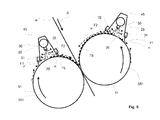
- figure 7 is shown a one-sided example with a nip and in figure 8 is shown a two-sided example where the application of the treatment substance is provided via rolls.
- figure 1 is shown the situation when the web W is far enough from the wall 10.
- the treatment zone 20 is lower pressure caused by the suction of air and mist of the treatment medium.
- the lower pressure draws a great amount of air into the treatment zone 20 through the inlet opening 15 between the wall 10 and the web W.
- FIGS 5A - 5D are some advantageous examples of the form of the wall 10 the inlet opening 15 ( figs. 1 - 4 ) such that the wall 10 is uneven in height and thus its distance from the web W ( figs. 1 - 4 ) varies such that in width direction the height of the inlet opening 15 alters at least partly at wall openings 11.
- the form of the wall 10 is provided with continuous wavelike pattern, the higher part of the wave being closer to the web W and the opening for replacement air is created by the lower part of the wave, as indicated in the figures by wall openings 11.
- the form of the wall 10 to be uneven has been constructed by attaching wires or corresponding protruding parts 12 on the wall 10 spaced apart at a distance from each other and forming the openings for replacement air and thus creating wall openings 11.
- the uneven form of the wall 10 such that wall openings 11 are provided can be constructed by many various forms and patterns; it can be of continuous or discontinuous pattern, different types of wavelike forms can be designed, It can be constructed by forming the wall 10, it can be created by using separate parts attached to the wall etc.
- the fiber web W is passed through the inlet opening 15 between the walls 10 into the treatment zone 20 in which a treatment devices 30 are located for applying a treatment agent onto the passing fiber web by spraying means 25 onto the both sides of the web.
- slit nozzles 31 for example float nozzles, are arranged to provide gas flows F1, preferably air flows, at least partially towards the passing fiber web W, advantageously inclined in relation to the running direction S of the fiber web W, as shown in the figure.
- the main components of the gas flows are indicated in the figure by arrows F1.
- the spraying means 25 are located in the treatment zone and the treatment zone 20 further comprises removal channels 43 for removing the treatment substance mist from the treatment zone 20 from both sides of the web W.
- slit nozzles 32 are arranged to provide gas flows F2, preferably air flows, at least partially towards the passing fiber web W, advantageously inclined in relation to the running direction S of the fiber web W, as shown in the figure.
- the main components of the gas flows are indicated in the figure by arrows F2.
- the gas flows F1, F2 in connection with the inlet opening 15 and the outlet opening 35 provide sealing means for preventing the treatment substance mist to spread from the treatment zone 20.
- the gas flows F1, F2 directed at least partially opposite to each other create an over pressurized area in between for supporting and stabilizing the web W.
- treatment substance is applied by spraying means 25 of a treatment device 30, for example a spraying device 30.
- the treatment device 30 is located in the area of the closing between the web W and the roll 51.
- the treatment device 30 has nozzles or corresponding means such that gas flows F1; F2 are provided, one gas flow F1 at the inlet opening 15 and another between the treatment device 30 and the roll 51.
- the gas flows F1, F2 create an over pressurized area at the treatment zone 20.
- the rotation direction of the roll 51 is indicated by arrow S51 and the treatment device 30 also comprises a doctor 57.
- treatment devices 30 for applying treatment substance on the both surfaces of the in direction S passing fiber web W are located inside a hood 45.
- the treatment devices 30 apply the treatment substance TS by spraying means 25 onto the surfaces of an in directions S51 rotating rolls 51 and in the nip formed between the rolls 51 the treatment substance TS is applied onto the both surfaces of the fiber web.
- the treatment device 20 comprises a treatment zone 20, such as a spraying zone 20, in which the treatment substance is applied by spraying means 25.
- the treatment zone 20 is located inside the hood 45 and the means 31, 32 for providing gas flows F1, F2 are located at the inlet 15 and the outlet 35 opening of the treatment zone 20 i.e.
- nozzles providing gas flows F1, F2 are located at the inlet and at the outlet edge of the hood 45.
- gas flows F1 at the inlet edge the air flows created by the moving surface the rotating rolls 51 is prevented and which air flow would otherwise create harmful turbulent flows and the flow the treatment substance mist flow is directed towards the surface of the roll 51.
- dashed line arrows air and mist flows are indicated.
Abstract
Description
- The invention relates to a device for treating a fiber web. Especially the invention relates to a device for applying treatment substance on at least one surface of the fiber web, which device for applying treatment substance on the at least one surface of the fiber web may apply the treatment substance directly onto the at least one surface of the web or the treatment substance may be applied onto the at least one surface of the web via a roll onto surface of which the device is provided to apply the treatment substance. In particular the invention relates to a device according to the preamble of claim 1.
- As known from the prior art in fiber web producing processes typically comprise an assembly formed by a number of apparatuses arranged consecutively in the process line. A typical production and treatment line comprises a head box, a wire section and a press section as well as a subsequent drying section and a reel-up. The production and treatment line can further comprise other devices and sections for finishing the fiber web, for example, a sizer, a calender, a coating section. The production and treatment line also comprises at least one winder for forming customer rolls as well as a roll packaging apparatus. In this description and the following claims by fiber webs are meant for example paper and board webs.
- In production of fiber webs, for example of paper or board webs, sizing is used to alter the properties of a fiber web by adding sizing agents, for example glue chemicals. In surface sizing the sizing agent is added onto the surface of the fiber web directly or via a roll at the dry end of the fiber web machine. Internal sizing is done at the wet end of the fiber web machine by using different kinds of chemical treatments in order to influence the penetration of a liquid, for example of water into the fiber web. By sizing the strength properties of the fiber web are increased and also the dusting of the fiber web is decreased.
- The sizing of paper and board web typically utilize a separate sizer. In connection with the sizer different kinds of sizing technology are employed in prior art arrangements, for example pond sizing technology or film-transfer technology or spray sizing technology.
- Coated fiber web grades and coating are becoming more and more popular and thus the coating processed and equipment have increasing demands imposed thereon. In coating, especially in pigment coating the surface of a fiber web is formed with a layer of coating paste (coating agent) at a coating station followed by drying. The formation of a coating paste can be divided in supplying the coating paste onto the web surface directly or via a roll, which is called the application of the coating paste, as well as in the adjustment of final amount of coating paste.
- The coating of paper and board web typically utilize a coating device - a coater. In connection with the coater different kinds of coating technology are employed in prior art arrangements, for example curtain technology or blade coating technology or rod coating technology or air brush coating technology or spray coating technology.
- In
FI patent application 20075348 DE 102008021541 ) is disclosed a process for treatment of a fiber web in which treatment medium is applied on a surface of the web by guiding the web through an inlet slot in an application zone in which a spraying nozzle is located. The treatment medium is applied on the web by the nozzle and then the web is guided through a nip formed between two passing surfaces. In the process air and fog of the treatment medium is removed from the application zone through a discharge channel in which an organ is arranged for creating in the application zone a lower pressure level than the ambient pressure. - In
FI patent application 20096039 DE 10210040291 ) a device is disclosed a spraying arrangement which comprises at least one treatment zone and an inlet opening for a fiber web. The inlet opening comprises converging surface which in relation to the running track of the web converges in the direction of the web to insist an air flow flowing with the web to pack in pressure zone formed between the web and the converging surface and the converging surface is also provided for preventing the flow of air or mist of the treatment medium out through the inlet slot. - In prior art arrangements an inlet opening / inlet slot of the application chamber / spraying chamber / treatment zone has typically been relatively narrow. In practice the opening must not be too wide since it would make it possible for too much air to flow in the treatment zone but the opening must be wide enough for providing enough space between the web and the edge surface of the opening. In case there is too little space the web would contact the edge of the opening and scrape against the surface and cause fluttering of the web.
- The scraping of the web against the surface of the edge causes wear of the surface and of the web, and also dusting. The dust and dirt caused by the scraping may cause problems in the treatment zone and make the running time of the arrangement for a long period almost impossible. The scraping and the fluttering of the web may also cause web breaks.
- In prior art arrangements treatment zone is usually in lower pressure than the ambient pressure for preventing the air and mist of the treatment medium from flowing out through the inlet opening. In case the inlet opening is made bigger more air / mist must be removed from the treatment zone by suction which increases energy consumption significantly. It may also cause quality or running problems due to insufficient suction capacity for example due to mist forming into droplets that drop on the web or due to accumulations of treatment medium causing web breaks. As in the present days the running speeds of fiber web machines tend to increase and simultaneously the web width of the fiber webs to be produced tend to widen also more capacity is needed of the means creating the lower pressure in the treatment zone, for example of blowers. This means significantly more energy consumption and more costs since more efficient means are needed or their number must be increased in order to create the sufficient suction effect in the treatment zone.
- It is known from prior art that spraying arrangement is located on one or on both sides of the fiber web. In the arrangements that comprise spraying on both sides of the web one problem is that the lower pressure than the ambient pressure prevails on both sides of the fiber web which further increases the runnability problems of the fiber web especially instability of the web easily increases and in case the arrangement is of the nip-less type i.e. the treatment zone is not followed by a nip, the case is even more problematic and especially if both sides of the web is provided with the spraying arrangement. These factors thus also lead to increased need of suction capacity.
- Generally speaking one of the main weaknesses in known prior art arrangements is the problem of instability of the fiber web which leads to the need of increased suction air in order to reach the stability of the fiber web run.
- It is also known from prior art that often in spraying arrangements the spraying means are located inside a hood that also prevents the treatment mist comprising mist droplets of moisture and treatment substance to spread outside the treatment zone of the spraying arrangement. As preventing means typically are used suction nozzles located at the outlet side of the hood i.e. at the side from which the fiber web to be treated is guided out from the treatment zone. The suction nozzles remove air and mist via a suction channel to mist separator and further out from the suction device. At the inlet side the air flow provided by the passing fiber web usually prevents at least partially the spreading of the mist from the treatment zone. As preventing means it is also know to locate the edges of the hood as close as the fiber web as possible but by this full control of mist is not achieved. The suction device needed from removing and separating the mist needs a large amount of air for creating a fast enough flow to remove the mist all the way to the separator in order to keep the suction device clean. The mist separator is typically expensive and rather complicated equipment and also the space needed for the channels and the device in itself might cause space problems in some cases.
- An object of the invention is provide a device in which above disadvantages of the prior art arrangements are eliminated or at least minimized.
- Another object of the invention is to provide a device in which less suction air is needed and thus the energy consumption is lower.
- A further non-necessary object of the invention is to eliminate or at least minimize the disadvantages of prior art relating to the stability of the fiber web run in a treatment zone, especially in a spraying zone where surface treatment agent such as sizing agent or coating agent is applied, especially sprayed, onto the passing fiber web.
- A further non-necessary object of the invention is to eliminate or at least minimize the disadvantages of prior art relating to mist removal from the treatment zone.
- In order to achieve the above objects the device according to the invention is mainly characterized by the features of the characterizing part of claim 1.
- According to the invention a device for applying treatment substance on at least one surface of the fiber web, which treatment device for applying treatment substance on the at least one surface of the fiber web may apply the treatment substance directly onto the at least one surface of the web or the treatment substance may be applied onto the at least one surface of the web via a roll onto surface of which the treatment device is provided to apply the treatment substance, which device comprises a treatment zone, such as a spraying zone, in which the treatment substance is applied. The device comprises means for providing gas flows at least at one of the inlet or the outlet opening of the treatment zone.
- According to an advantageous aspect of the invention the device for treating a fiber web, in particular a device for applying treatment substance on at least one surface of the fiber web directly or via a roll, which device comprises a treatment zone, such as a spraying zone, to which zone the fiber web is driven through an inlet opening limited by at least one wall. The device comprises means for providing gas flows that influence the run of the passing fiber web for stabilizing the run of the fiber web in the treatment zone. The means influencing the run of the passing fiber web comprise that at least one wall of the inlet opening of the device is uneven in height in width direction of the inlet opening such that wall openings are provided for replacement air entering the treatement zone or the means providing gas flows influencing the run of the passing fiber web comprise nozzle means for pressurizing the treatment zone to a higher pressure than the ambient pressure.
- According to first embodiment of the invention the inlet opening of the treatment zone, which is formed by at least one wall limiting the inlet opening, is provided with at least one uneven, advantageously non-linear, for example wavelike wall form. The form of the wall thus alters in the width direction of the inlet opening. By this the inlet opening provides air to the treatment zone but the uneven forming of at least one edge prevents the web to contact the wall. In case the web is driven close to the wall in the treatment zone the lower pressure begins to effect between the wall and the web instead of as in prior art arrangements pulling the web to contact the wall the lower pressure draws air through the open parts created by the unevenness of the wall in the opening into the treatment zone and thus prevents the web to contact the wall.
- By the inventive uneven form of the wall of the inlet opening in this first embodiment of the invention the contact of the web is prevented and thus it is possible to provide narrower inlet opening than in case of even form of wall is used. The narrower inlet opening in turn makes it possible to use smaller suction air amounts and due to this significant energy savings are achieved.
- According to the first embodiment of the advantageous aspect of the invention the device for treating a fiber web, in particular a device for applying treatment substance for treating a passing fiber web on at least one surface of the fiber web, comprises a treatment zone, such as a spraying zone, in which zone a lower pressure than the ambient pressure is provided and to which zone the fiber web is driven through an inlet opening limited by at least one wall. The at least one wall of the inlet opening of the device is uneven in height in width direction of the inlet opening such that wall openings are provided for replacement air entering the treatement zone. According to an advantageous feature the at least one wall has a continuous wavelike pattern. According to another advantageous feature the at least one wall comprises towards web protruding parts that are spaced apart such that wall openings are provided in between the protruding parts. According to advantageous aspect the device according to the first embodiment comprises correspondingly formed walls of the inlet opening on both sides of the fiber web.
- According to an advantageous feature of the invention the opening height is altered such that the difference between the narrowest part and the highest part is 10 - 90 %, advantageously 30 - 70 % of the height of the highest part.
- It should be note that terms narrow and high refer to the height of the opening, not to the width of the opening in the width direction of the web. By narrow is meant opening having height of 30 - 70 mm, advantageously 45 - 55 mm, measured from the web to the closest part of the wall limiting the inlet opening. The air amount is 100 - 1200 m3/h/m, advantageously 500 - 100m3/h/m of width of the web for one side of the web. Advantageously the under pressure in the treatment zone is on average 10 - 50 Pa compared to the ambient pressure.
- Even though the invention is here described mainly in reference to spray sizing and spray coating the inventive idea is utilizable also in other inlet type openings in which the web is led through a narrow opening to a treatment zone.
- According to the second embodiment of the advantageous aspect of the invention the device for treating a fiber web, in particular a device for applying treatment substance for treating a passing fiber web on at least one surface of the fiber web, comprises a treatment zone, such as a spraying zone, in which zone the fiber web is driven through an inlet opening limited by at least one wall. The device comprises at least one nozzle means for pressurizing the treatment zone to a higher pressure than the ambient pressure. Advantageously the over pressure in the treatment zone is on average 10 - 300 Pa compared to the ambient pressure. According to an advantageous feature of the invention the nozzle means for pressurizing the treatment zone comprises at least one slit nozzle located at the inlet opening providing gas flow, preferably air flow at least partially towards the passing fiber web. Preferably the means for pressurizing the treatment zone comprise two slit nozzles at one side of the passing fiber web providing gas flows at least partially towards the passing fiber web and one slit nozzle is located at the inlet opening and the other nozzle is located at an outlet opening of the treatment zone or before a treatment nip to which the treatment zone ends. The gas flows of the two slit nozzles may be directed at least partially opposite to each other and inclined in relation to the passing fiber web such that the flows of the two nozzles create an over pressurized area in between for supporting and stabilizing the web. The over pressurized area can also be created by flows that are not directed opposite to each other. According to advantageous aspect the device according to the second embodiment comprises corresponding means on both sides of the fiber web. According to an advantageous feature the gas flows provide simultaneously sealing means for preventing the treatments substance mist to spread from the treatment zone. According to an advantageous feature the slit nozzle is a float nozzle.
- According to an advantageous feature the device is provided with at least one removal channel for removing the treatment substance mist from the treatment zone.
- The device according to the advantageous aspect of invention is utilizable both in cases where the fiber web is guided through a nip after the treatment zone and in cases where the fiber web is guided from the treatment zone through an outlet opening. In case the invention is utilized in connection with a treatment zone with an outlet opening i.e. nip-less treatment advantageously the outlet opening is provided with sealing means, preferably based on sealing by gas flows.
- According to a third embodiment of another advantageous aspect of the invention a device for applying treatment substance on at least one surface of the fiber web, which device for applying treatment substance on the at least one surface of the fiber web may apply the treatment substance directly onto the at least one surface of the web or the treatment substance may be applied onto the at least one surface of the web via a roll onto surface of which the device is provided to apply the treatment substance, which device comprises a treatment zone, such as a spraying zone, in which the treatment substance is applied. In this embodiment the treatment zone is located inside a hood and the means for providing gas flows are located at the inlet and the outlet opening of the treatment zone i.e. nozzles providing gas flows are located at the inlet and at the outlet edge of the hood. By the gas flow at the inlet edge the air flow created by the moving surface of the passing fiber web or the rotating roll is prevented, which air flow would otherwise create harmful turbulent flows and increase the pressure in the treatment zone inside the hood. According to an advantageous feature by utilizing the ejector effect and the direction of the flow the mist flow is directed towards the surface of the fiber web or the roll. According to an advantageous feature by the amount and direction of the gas flow from the nozzles the mist adherence to the surface of the web or the roll is controlled. According to a further advantageous feature an adjustable slit is provided between the nozzle and the treatment zone by which gap part of the needed gas flow is provided. This enhances the gas flow and provides for increased adherence of the mist onto the surface of the fiber web or the roll without increasing the amount of suction needed for removing the mist uncontrollably.
- The above embodiments and advantageous features of the invention can be combined in various way to provide further advantages of the invention in spraying arrangements for treating a fiber web. In the above description by the terms first and second are not meant any preference of the embodiments but only to indicate the two advantageous aspects of the invention.
- In the following the invention is described in more detail with reference to the accompanying drawing in which
-
Figures 1 - 4 show schematically the behavior of gas flows and web in an inlet opening. -
Figures 5A - 5D show schematically some advantageous examples of the form of the inlet opening. -
Figure 6 shows schematically one advantageous example of the device. -
Figure 7 shows schematically one further advantageous example of the device. -
Figure 8 shows schematically yet one further advantageous example of the device. - In the figures and the following description by same reference signs are ind i-cated corresponding parts or subassemblies unless otherwise mentioned. In
figures 1 - 6 the inlet opening is referred byreference sign 15 and the wall is referred byreference sign 10. The web is referred by reference sign W and its running direction is marked by arrow S. In thefigures 1 - 4 by smaller arrows are referred to gas flows in the inlet opening 15 area of thetreatment zone 20, forexample spraying zone 20. The web W enters the treatment zone through the inlet opening 15 formed between the web W and thewall 10 of the beam, for example spray-beam. In thefigure 6 the gas flows are indicated by arrows F1; F2. Thefigures 1 - 5D are examples in which only one side of the fiber web W is treated but they are as well utilizable in connection with arrangements in which both sides of the fiber web are treated. In the example offigure 6 both sides of the fiber web are treated but correspondingly this arrangement is utilizable when only one side of the web is treated. Infigure 7 is shown a one-sided example with a nip and infigure 8 is shown a two-sided example where the application of the treatment substance is provided via rolls. - In
figure 1 is shown the situation when the web W is far enough from thewall 10. In thetreatment zone 20 is lower pressure caused by the suction of air and mist of the treatment medium. The lower pressure draws a great amount of air into thetreatment zone 20 through the inlet opening 15 between thewall 10 and the web W. - In
figure 2 the web W is close to thewall 10. The low pressure in thetreatment zone 20 increases significantly as the web W moves closer to thewall 10 since the air amount transmitted into thetreatment zone 20 with the web W decreases. - In
figure 3 the web W contacts thewall 10 and in theopening gap 21 between the wall and the web W greater low pressure creates and no replacement air is received outside thetreatment zone 20 and thus the web W stays in contact with thewall 10. - In
figure 4 the situation is as infigure 3 but thewall 10 is made uneven in height and thus its distance from the web W (figs. 1 - 4 ) varies such that in width direction the height of the inlet opening alters at least partly which is indicated by dashedwall openings 11 thus when the web W contacts thewall 10 still air is received to thetreatment zone 20 via openings between the web W and the wider parts of the inlet opening 15 i.e. between thewall openings 11 and the web W thus the force pulling the web W to contact with thewall 10 does not increase very much and the web W loosens from the contact with thewall 10. - In
figures 5A - 5D are some advantageous examples of the form of thewall 10 the inlet opening 15 (figs. 1 - 4 ) such that thewall 10 is uneven in height and thus its distance from the web W (figs. 1 - 4 ) varies such that in width direction the height of theinlet opening 15 alters at least partly atwall openings 11. - In the examples of
figures 5A, 5B and 5D the form of thewall 10 is provided with continuous wavelike pattern, the higher part of the wave being closer to the web W and the opening for replacement air is created by the lower part of the wave, as indicated in the figures bywall openings 11. - In the example of
figure 5C the form of thewall 10 to be uneven has been constructed by attaching wires or corresponding protrudingparts 12 on thewall 10 spaced apart at a distance from each other and forming the openings for replacement air and thus creatingwall openings 11. - The uneven form of the
wall 10 such thatwall openings 11 are provided can be constructed by many various forms and patterns; it can be of continuous or discontinuous pattern, different types of wavelike forms can be designed, It can be constructed by forming thewall 10, it can be created by using separate parts attached to the wall etc. - In the example of
figure 6 the fiber web W is passed through the inlet opening 15 between thewalls 10 into thetreatment zone 20 in which atreatment devices 30 are located for applying a treatment agent onto the passing fiber web by sprayingmeans 25 onto the both sides of the web. In connection with thewalls 10 of the inlet opening 15 on both sides of the web W slitnozzles 31, for example float nozzles, are arranged to provide gas flows F1, preferably air flows, at least partially towards the passing fiber web W, advantageously inclined in relation to the running direction S of the fiber web W, as shown in the figure. The main components of the gas flows are indicated in the figure by arrows F1. The spraying means 25 are located in the treatment zone and thetreatment zone 20 further comprisesremoval channels 43 for removing the treatment substance mist from thetreatment zone 20 from both sides of the web W. At the outlet opening 35 at the end of thetreatment zone 20slit nozzles 32, for example float nozzles, are arranged to provide gas flows F2, preferably air flows, at least partially towards the passing fiber web W, advantageously inclined in relation to the running direction S of the fiber web W, as shown in the figure. The main components of the gas flows are indicated in the figure by arrows F2. The gas flows F1, F2 in connection with theinlet opening 15 and theoutlet opening 35 provide sealing means for preventing the treatment substance mist to spread from thetreatment zone 20. The gas flows F1, F2 directed at least partially opposite to each other create an over pressurized area in between for supporting and stabilizing the web W. - In arrangements where the outlet from the treatment zone is arranged as a treating nip also mechanical sealing can be used to prevent the treatment substance mist to spread from the treatment zone.
- In the example of
figure 7 onto the in direction S passing fiber web W treatment substance is applied by sprayingmeans 25 of atreatment device 30, for example aspraying device 30. Thetreatment device 30 is located in the area of the closing between the web W and theroll 51. Thetreatment device 30 has nozzles or corresponding means such that gas flows F1; F2 are provided, one gas flow F1 at theinlet opening 15 and another between thetreatment device 30 and theroll 51. The gas flows F1, F2 create an over pressurized area at thetreatment zone 20. The rotation direction of theroll 51 is indicated by arrow S51 and thetreatment device 30 also comprises adoctor 57. - In the example of
figure 8 invention treatment devices 30 for applying treatment substance on the both surfaces of the in direction S passing fiber web W are located inside ahood 45. Thetreatment devices 30 apply the treatment substance TS by sprayingmeans 25 onto the surfaces of an in directionsS51 rotating rolls 51 and in the nip formed between therolls 51 the treatment substance TS is applied onto the both surfaces of the fiber web. Thetreatment device 20 comprises atreatment zone 20, such as a sprayingzone 20, in which the treatment substance is applied by sprayingmeans 25. Thetreatment zone 20 is located inside thehood 45 and themeans inlet 15 and theoutlet 35 opening of thetreatment zone 20 i.e. nozzles providing gas flows F1, F2 are located at the inlet and at the outlet edge of thehood 45. By the gas flows F1 at the inlet edge the air flows created by the moving surface the rotating rolls 51 is prevented and which air flow would otherwise create harmful turbulent flows and the flow the treatment substance mist flow is directed towards the surface of theroll 51. In thefigure 8 by dashed line arrows air and mist flows are indicated. - Above the invention has been described by referring to some advantageous examples only. Many modifications and variations are possible within the inventive idea.
-
- 10
- wall
- 11
- wall opening
- 12
- protruding part
- 15
- inlet opening
- 20
- treatment zone
- 21
- opening gap
- 25
- spraying means
- 30
- treatment device
- 31, 32
- slit nozzle
- 35
- outlet opening
- 43
- removal channel
- 45
- hood
- 51
- roll
- 57
- doctor
- F1; F2
- gas flows
- S
- running direction of the web
- S51
- rotation direction of the roll
- TS
- treatment substance
- W
- web
Claims (15)
- Device for applying treatment substance on at least one surface of the fiber web at a treatment zone (20), which treatment device (30) for applying treatment substance on the at least one surface of the fiber web (W) is provided to apply the treatment substance (TS) directly onto the at least one surface of the fiber web (W) or the treatment substance is provided to be applied by the treatment device (30) onto the at least one surface of the fiber web (W) via a rotating roll (51) onto surface of which the treatment device (51) is provided to apply the treatment substance (TS), characterized in, that the treatment device (30) comprises means (11; 31, 32) for providing gas flows (F1, F2) at least at one of the inlet or the outlet opening (15; 35) of the treatment zone (20).
- Device according to claim 1for applying treatment substance for treating a passing fiber web on at least one surface of the fiber web, which device comprises a treatment zone (20), such as a spraying zone, to which zone (20) the fiber web (W) is driven through an inlet opening (15) limited by at least one wall (10), characterized in, that the device comprises means (11; 31) at least at the inlet opening (15) for providing gas flows that influence the run of the passing fiber web (W) for stabilizing the run of the fiber web (W).
- Device according to claim 2, in which the treatment zone (20) with a lower pressure than the ambient pressure is provided, characterized in, that the means providing gas flows influencing the run of the passing fiber web (W) comprise that at least one wall (10) of the inlet opening (15) of the device is uneven in height in width direction of the inlet opening (15) such that wall openings (11) are provided for replacement air entering the treatement zone (20).
- Device according to claim 2 or 3, characterized in, that the at least one wall (10) limiting the inlet opening has a continuous wavelike pattern.
- Device according to claim 2 or 3, characterized in, that the at least one wall (10) limiting the inlet opening comprises towards the web protruding parts (12) that are spaced apart such that wall openings (11) are provided in between the protruding parts (12).
- Device according to any of claims 2 or 3, characterized in, that the opening height of the inlet opening (15) is altered such that the difference between the narrowest part and the highest part is 10 - 90 %, advantageously 30 - 70 % of the height of the highest part.
- Device according to claim 2 or 3, characterized in, that the inlet opening (15) is formed between two walls (10) and at least one of the walls (10) is uneven in height.
- Device according to claim 2, characterized in, that the means providing gas flows influencing the run of the passing fiber web comprise at least one nozzle means (31) providing gas flows (F1) for pressurizing the treatment zone (20) to a higher pressure than the ambient pressure.
- Device according to claim 2 or 8, characterized in, that the nozzle means for pressurizing the treatment zone (20) to a higher pressure than the ambient pressure comprises at least one slit nozzle (31) located at the inlet opening (15) providing gas flow (F1), preferably air flow at least partially towards the passing fiber web (W).
- Device according to claim 2 or 8, characterized in, that the over pressure in the treatment zone (20) is on average 10 - 300 Pa compared to the ambient pressure.
- Device according to claim 2 or 8, characterized in, that the nozzle means for pressurizing the treatment zone comprise two slit nozzles (31, 32) at one side of the passing fiber web (W) providing gas flows (F1, F2) at least partially towards the passing fiber web (W) and that one of the slit nozzles (31) is located at the inlet opening (15) and the other one of the slit nozzles (32) is located at an outlet opening (32) of the treatment zone (20) or before a treatment nip to which the treatment zone (20) ends.
- Device according to claim 11, characterized in, that the gas flows (F1, F2) of the two slit nozzles (31, 32) are directed at least partially opposite to each other and inclined in relation to the passing fiber web (W) such that the flows of the two nozzles create an over pressurized area in between for supporting and stabilizing the web.
- Device according to claim 1 for applying treatment substance (TS) on the at least one surface of the fiber web (W) directly onto the at least one surface of the fiber web (W) or onto the at least one surface of the fiber web (W) via a rotating roll (51) onto surface of which the treatment device (30) is provided to apply the treatment substance (TS), which device comprises a treatment zone (20), such as a spraying zone, in which the treatment substance (TS) is applied and which treatment zone (20) is located inside a hood (45) characterized in, that the means (31, 32) for providing gas flows (F1,F2) are located at the inlet and the outlet opening (10, 35) of the treatment zone (20).
- Device according to claim 13, characterized in, that the means (31, 32) for providing the gas flows (F1, F2) are nozzles (31, 32) located at the inlet and at the outlet edge of the hood (45) and that by the ejector effect and the direction of the gas flows (F1, F2) treatment substance mist flow is directed towards the surface of the fiber web (W) or of the roll (51).
- Device according to any of the previous claims, characterized in, that the device comprises corresponding means on both sides of the passing fiber web.
Priority Applications (3)
| Application Number | Priority Date | Filing Date | Title |
|---|---|---|---|
| EP14183544.7A EP2811069B1 (en) | 2012-11-22 | 2012-11-22 | Device for treating a fiber web |
| EP12193721.3A EP2735648A1 (en) | 2012-11-22 | 2012-11-22 | Device for treating a fiber web |
| CN201310574251.6A CN103835187B (en) | 2012-11-22 | 2013-11-15 | For processing the equipment of fiber web |
Applications Claiming Priority (1)
| Application Number | Priority Date | Filing Date | Title |
|---|---|---|---|
| EP12193721.3A EP2735648A1 (en) | 2012-11-22 | 2012-11-22 | Device for treating a fiber web |
Related Child Applications (1)
| Application Number | Title | Priority Date | Filing Date |
|---|---|---|---|
| EP14183544.7A Division EP2811069B1 (en) | 2012-11-22 | 2012-11-22 | Device for treating a fiber web |
Publications (1)
| Publication Number | Publication Date |
|---|---|
| EP2735648A1 true EP2735648A1 (en) | 2014-05-28 |
Family
ID=47227645
Family Applications (2)
| Application Number | Title | Priority Date | Filing Date |
|---|---|---|---|
| EP12193721.3A Withdrawn EP2735648A1 (en) | 2012-11-22 | 2012-11-22 | Device for treating a fiber web |
| EP14183544.7A Active EP2811069B1 (en) | 2012-11-22 | 2012-11-22 | Device for treating a fiber web |
Family Applications After (1)
| Application Number | Title | Priority Date | Filing Date |
|---|---|---|---|
| EP14183544.7A Active EP2811069B1 (en) | 2012-11-22 | 2012-11-22 | Device for treating a fiber web |
Country Status (2)
| Country | Link |
|---|---|
| EP (2) | EP2735648A1 (en) |
| CN (1) | CN103835187B (en) |
Cited By (3)
| Publication number | Priority date | Publication date | Assignee | Title |
|---|---|---|---|---|
| DE102014100651A1 (en) * | 2014-01-21 | 2015-07-23 | Paperchine Gmbh | Air sealing device for a spraying apparatus in a papermaking machine |
| EP2985385A1 (en) * | 2014-08-11 | 2016-02-17 | Xavier Blanch Andreu | Spraying device for spraying a liquid product onto paper sheet |
| WO2022008129A1 (en) * | 2020-07-08 | 2022-01-13 | Voith Patent Gmbh | Coating system and coating method |
Families Citing this family (5)
| Publication number | Priority date | Publication date | Assignee | Title |
|---|---|---|---|---|
| EP3219849A1 (en) | 2016-03-15 | 2017-09-20 | Valmet Technologies Oy | Device for treating fiber webs |
| CN106676966B (en) * | 2016-07-26 | 2017-10-31 | 联盛纸业(龙海)有限公司 | A kind of paper sizing dyeing production and device |
| DE102018124521A1 (en) * | 2018-10-04 | 2020-04-09 | Brückner Maschinenbau GmbH & Co. KG | Treatment plant for a flexible material web that can be passed through a treatment furnace, in particular plastic film |
| EP3842591A1 (en) | 2019-12-23 | 2021-06-30 | Andritz Küsters GmbH | Device for applying an applied medium |
| JP7194719B2 (en) * | 2020-10-28 | 2022-12-22 | 本田技研工業株式会社 | Material layer forming device |
Citations (10)
| Publication number | Priority date | Publication date | Assignee | Title |
|---|---|---|---|---|
| WO1995008026A1 (en) * | 1993-09-14 | 1995-03-23 | J. M. Voith Gmbh | Process and device for coating a travelling material web |
| WO1997013036A1 (en) * | 1995-10-05 | 1997-04-10 | Valmet Corporation | Method and apparatus for coating a moving paper or cardboard web |
| US5849321A (en) * | 1994-07-01 | 1998-12-15 | Valmet Corporation | Method and apparatus for spray-coating a paper or board web |
| WO2000042254A1 (en) * | 1999-01-18 | 2000-07-20 | Metso Paper, Inc. | Spray-coating method and spray-coater |
| WO2002072953A1 (en) * | 2001-03-13 | 2002-09-19 | Metso Paper, Inc. | Assembly for treating a web of paper or paperboard |
| EP1541242A1 (en) * | 2002-07-31 | 2005-06-15 | Maintech Co., Ltd. | Liquid spray unit, method for spraying liquid using it, and chemical |
| WO2005103380A1 (en) * | 2004-04-20 | 2005-11-03 | Metso Paper Karlstad Ab | Protecting device for spraying equipment and method of protecting it and its surroundings |
| DE102008021541A1 (en) | 2007-05-14 | 2008-11-20 | Metso Paper, Inc. | Procedure for the treatment of paper- or cardboard web or a corresponding fiber web, comprises applying a treatment medium on a surface of the web by guiding the web through an inlet slot in an application chamber |
| DE102010040291A1 (en) | 2009-10-09 | 2011-04-14 | Metso Paper, Inc. | Device, useful for supporting a fibrous web for surface sizing and treating, comprises an inlet opening for web with a converging surface, which converges in direction of web to insist leading air flow from web through converging surface |
| DE202011107823U1 (en) * | 2010-08-31 | 2011-11-25 | Metso Paper, Inc. | Plant for processing a fiber web |
Family Cites Families (7)
| Publication number | Priority date | Publication date | Assignee | Title |
|---|---|---|---|---|
| FI97247C (en) | 1994-07-01 | 1998-07-21 | Valmet Paper Machinery Inc | Spray coating method and apparatus |
| DE20023956U1 (en) | 2000-11-22 | 2007-12-06 | Voith Patent Gmbh | Curtain coater |
| DE10339262A1 (en) | 2003-08-26 | 2005-03-17 | Voith Paper Patent Gmbh | Web guiding means |
| DE10358754B4 (en) | 2003-12-12 | 2011-07-14 | M-Real Oyj | Rail conveyor |
| DE102004018768A1 (en) | 2004-04-17 | 2005-11-03 | Voith Paper Patent Gmbh | Guide system for paper strip comprises rollers with porous surface guiding strip in Z-shaped path, rollers being mounted at fixed distance from curtain-coating units which coat each side of strip, rollers being mounted on each coated side |
| DE102006036450A1 (en) | 2006-08-04 | 2008-02-07 | Voith Patent Gmbh | applicator |
| DE102010041713A1 (en) | 2010-09-30 | 2012-04-05 | Voith Patent Gmbh | Device for direct or indirect application of liquid to pasty application medium and method for operating such a device |
-
2012
- 2012-11-22 EP EP12193721.3A patent/EP2735648A1/en not_active Withdrawn
- 2012-11-22 EP EP14183544.7A patent/EP2811069B1/en active Active
-
2013
- 2013-11-15 CN CN201310574251.6A patent/CN103835187B/en active Active
Patent Citations (11)
| Publication number | Priority date | Publication date | Assignee | Title |
|---|---|---|---|---|
| WO1995008026A1 (en) * | 1993-09-14 | 1995-03-23 | J. M. Voith Gmbh | Process and device for coating a travelling material web |
| US5849321A (en) * | 1994-07-01 | 1998-12-15 | Valmet Corporation | Method and apparatus for spray-coating a paper or board web |
| WO1997013036A1 (en) * | 1995-10-05 | 1997-04-10 | Valmet Corporation | Method and apparatus for coating a moving paper or cardboard web |
| US6063449A (en) * | 1995-10-05 | 2000-05-16 | Valmet Corporation | Method and apparatus for coating a moving paper or cardboard web |
| WO2000042254A1 (en) * | 1999-01-18 | 2000-07-20 | Metso Paper, Inc. | Spray-coating method and spray-coater |
| WO2002072953A1 (en) * | 2001-03-13 | 2002-09-19 | Metso Paper, Inc. | Assembly for treating a web of paper or paperboard |
| EP1541242A1 (en) * | 2002-07-31 | 2005-06-15 | Maintech Co., Ltd. | Liquid spray unit, method for spraying liquid using it, and chemical |
| WO2005103380A1 (en) * | 2004-04-20 | 2005-11-03 | Metso Paper Karlstad Ab | Protecting device for spraying equipment and method of protecting it and its surroundings |
| DE102008021541A1 (en) | 2007-05-14 | 2008-11-20 | Metso Paper, Inc. | Procedure for the treatment of paper- or cardboard web or a corresponding fiber web, comprises applying a treatment medium on a surface of the web by guiding the web through an inlet slot in an application chamber |
| DE102010040291A1 (en) | 2009-10-09 | 2011-04-14 | Metso Paper, Inc. | Device, useful for supporting a fibrous web for surface sizing and treating, comprises an inlet opening for web with a converging surface, which converges in direction of web to insist leading air flow from web through converging surface |
| DE202011107823U1 (en) * | 2010-08-31 | 2011-11-25 | Metso Paper, Inc. | Plant for processing a fiber web |
Cited By (5)
| Publication number | Priority date | Publication date | Assignee | Title |
|---|---|---|---|---|
| DE102014100651A1 (en) * | 2014-01-21 | 2015-07-23 | Paperchine Gmbh | Air sealing device for a spraying apparatus in a papermaking machine |
| DE102014100651B4 (en) * | 2014-01-21 | 2015-08-13 | Paperchine Gmbh | Air sealing device for a spraying apparatus in a papermaking machine |
| EP2985385A1 (en) * | 2014-08-11 | 2016-02-17 | Xavier Blanch Andreu | Spraying device for spraying a liquid product onto paper sheet |
| EP2985386A1 (en) * | 2014-08-11 | 2016-02-17 | Blanch Andreu, Xavier | Spraying device for spraying a liquid product onto a paper web |
| WO2022008129A1 (en) * | 2020-07-08 | 2022-01-13 | Voith Patent Gmbh | Coating system and coating method |
Also Published As
| Publication number | Publication date |
|---|---|
| EP2811069A1 (en) | 2014-12-10 |
| EP2811069B1 (en) | 2018-08-29 |
| CN103835187B (en) | 2017-03-01 |
| CN103835187A (en) | 2014-06-04 |
Similar Documents
| Publication | Publication Date | Title |
|---|---|---|
| EP2811069B1 (en) | Device for treating a fiber web | |
| FI108061B (en) | Method for coating a paper or cardboard web | |
| EP0682571B1 (en) | Method and apparatus for coating paper or the like | |
| US8425721B2 (en) | Method and apparatus for treating a fibrous web | |
| US7022185B2 (en) | Apparatus for treating a web of paper or paperboard | |
| CA1298079C (en) | Coating apparatus and method | |
| JP2005511902A (en) | Method and apparatus for applying material to a web | |
| FI97817C (en) | Method and arrangement for coating a moving track | |
| FI113883B (en) | Methods and devices for processing a web of material and for controlling the behavior of the web of material | |
| EP3219849A1 (en) | Device for treating fiber webs | |
| US6855373B2 (en) | Method and device relating to coating a running web | |
| US7326301B2 (en) | Application device | |
| US6491791B1 (en) | Apparatus and method for treating roll surfaces and/or fabrics | |
| US5720816A (en) | Reverse feed film applicator | |
| EP2868802A1 (en) | Arrangement of a fiber web production line and method of a fiber web production line | |
| FI111562B (en) | A method and apparatus for applying a treating agent to a moving surface | |
| EP2894254B1 (en) | Coating device for applying coating color onto a fiber web and method for coating of a fiber web | |
| EP2860312A1 (en) | Arrangement of a fiber web production line and method of a fiber web production line | |
| US7399381B2 (en) | Machine for producing and treating a sheet of material | |
| FI99034B (en) | Method and arrangement in the wire gauze sections of a papermaking machine | |
| JPH0522066U (en) | Coating equipment | |
| EP1403428A1 (en) | Device for applying a fluid or pasty material onto a moving fibrous web |
Legal Events
| Date | Code | Title | Description |
|---|---|---|---|
| PUAI | Public reference made under article 153(3) epc to a published international application that has entered the european phase |
Free format text: ORIGINAL CODE: 0009012 |
|
| 17P | Request for examination filed |
Effective date: 20121122 |
|
| AK | Designated contracting states |
Kind code of ref document: A1 Designated state(s): AL AT BE BG CH CY CZ DE DK EE ES FI FR GB GR HR HU IE IS IT LI LT LU LV MC MK MT NL NO PL PT RO RS SE SI SK SM TR |
|
| AX | Request for extension of the european patent |
Extension state: BA ME |
|
| R17P | Request for examination filed (corrected) |
Effective date: 20140826 |
|
| RBV | Designated contracting states (corrected) |
Designated state(s): AL AT BE BG CH CY CZ DE DK EE ES FI FR GB GR HR HU IE IS IT LI LT LU LV MC MK MT NL NO PL PT RO RS SE SI SK SM TR |
|
| 17Q | First examination report despatched |
Effective date: 20180202 |
|
| STAA | Information on the status of an ep patent application or granted ep patent |
Free format text: STATUS: THE APPLICATION IS DEEMED TO BE WITHDRAWN |
|
| 18D | Application deemed to be withdrawn |
Effective date: 20180613 |