EP2860312B1 - Arrangement of a fiber web production line and method of a fiber web production line - Google Patents
Arrangement of a fiber web production line and method of a fiber web production line Download PDFInfo
- Publication number
- EP2860312B1 EP2860312B1 EP13187694.8A EP13187694A EP2860312B1 EP 2860312 B1 EP2860312 B1 EP 2860312B1 EP 13187694 A EP13187694 A EP 13187694A EP 2860312 B1 EP2860312 B1 EP 2860312B1
- Authority
- EP
- European Patent Office
- Prior art keywords
- nozzles
- fiber web
- nozzle row
- treatment substance
- substance
- Prior art date
- Legal status (The legal status is an assumption and is not a legal conclusion. Google has not performed a legal analysis and makes no representation as to the accuracy of the status listed.)
- Active
Links
Images


Classifications
-
- D—TEXTILES; PAPER
- D21—PAPER-MAKING; PRODUCTION OF CELLULOSE
- D21H—PULP COMPOSITIONS; PREPARATION THEREOF NOT COVERED BY SUBCLASSES D21C OR D21D; IMPREGNATING OR COATING OF PAPER; TREATMENT OF FINISHED PAPER NOT COVERED BY CLASS B31 OR SUBCLASS D21G; PAPER NOT OTHERWISE PROVIDED FOR
- D21H23/00—Processes or apparatus for adding material to the pulp or to the paper
- D21H23/02—Processes or apparatus for adding material to the pulp or to the paper characterised by the manner in which substances are added
- D21H23/22—Addition to the formed paper
- D21H23/50—Spraying or projecting
-
- B—PERFORMING OPERATIONS; TRANSPORTING
- B05—SPRAYING OR ATOMISING IN GENERAL; APPLYING FLUENT MATERIALS TO SURFACES, IN GENERAL
- B05B—SPRAYING APPARATUS; ATOMISING APPARATUS; NOZZLES
- B05B12/00—Arrangements for controlling delivery; Arrangements for controlling the spray area
- B05B12/14—Arrangements for controlling delivery; Arrangements for controlling the spray area for supplying a selected one of a plurality of liquids or other fluent materials or several in selected proportions to a spray apparatus, e.g. to a single spray outlet
-
- B—PERFORMING OPERATIONS; TRANSPORTING
- B05—SPRAYING OR ATOMISING IN GENERAL; APPLYING FLUENT MATERIALS TO SURFACES, IN GENERAL
- B05B—SPRAYING APPARATUS; ATOMISING APPARATUS; NOZZLES
- B05B13/00—Machines or plants for applying liquids or other fluent materials to surfaces of objects or other work by spraying, not covered by groups B05B1/00 - B05B11/00
- B05B13/02—Means for supporting work; Arrangement or mounting of spray heads; Adaptation or arrangement of means for feeding work
- B05B13/0207—Means for supporting work; Arrangement or mounting of spray heads; Adaptation or arrangement of means for feeding work the work being an elongated body, e.g. wire or pipe
Definitions
- the invention relates to an arrangement of a fiber web production line and to a method in a fiber web production line. Especially the invention relates to an arrangement and to a method of a coating or sizing section of a fiber web production line, in which section the coating or sizing medium is applied on the fiber web by spray means. More especially the invention relates to an arrangement according to the preamble part of claim 1 and to a method according to the preamble part of claim 6.
- a typical production and treatment line comprises a head box, a wire section and a press section as well as a subsequent drying section and a reel-up.
- the production and treatment line can further comprise other devices and sections for finishing the fiber web, for example, a sizer, a calender, a coating section.
- the production and treatment line typically also comprises a reel-up and at least one winder for winding customer rolls as well as at least one roll packaging apparatus.
- sizing is used to alter the properties of a fiber web by adding sizing agents (sizing medium), for example glue chemicals.
- Sizing can be divided to internal sizing and surface sizing.
- internal sizing the sizing agent is added to pulp in the wet end of the fiber web machine before forming.
- surface sizing the sizing agent is added onto the surface of the fiber web at the dry end of the fiber web machine.
- a coating in production of fiber webs, for example of paper or board webs, in coating, especially the surface of a fiber web is formed with a layer of coating color (coating medium) at a coating station followed by drying.
- the formation of a coating in direct coating applications can be divided in supplying the coating color onto the web surface, which is called the application of the coating color, as well as in the adjustment of final amount of coating color.
- the adjustment of the color amount is controlled already when supplying the color and therefore an additional adjustment is not needed.
- the coating or the sizing of a fiber web typically utilizes a coating device - a coater - or a sizing device - a sizer, which together with for example drying devices following the coater/sizer form the coating / sizing section of a fiber web production line.
- a coating device - a coater - or a sizing device - a sizer which together with for example drying devices following the coater/sizer form the coating / sizing section of a fiber web production line.
- different kinds of application technology for application of the coating or the sizing medium on the fiber web are employed in prior art arrangements, for example curtain technology or blade application technology or rod application technology or air brush application technology or spray application technology.
- the present invention relates to spray application technology.
- WO publication 2006/058961 A1 is disclosed a method and arrangement for processing a paper or board web or similar fiber web.
- a processing mixture is applied on the surface of the web with spray nozzles.
- WO publication 02/072953 is disclosed an assembly for treating a moving web of paper of board with web treatment substance which assembly comprises an application chamber located in at close vicinity of the moving web and facing the web and at least one linear nozzle array incorporating at least one nozzle for spraying the web treatment substance on the web.
- Fl utility model registration 9401 is disclosed a device for treating a fiber web, which comprises an application device, in particular a spraying device, for applying treatment substance on a moving fiber web.
- US 2003/120303 discloses a distribution pipe structure from steel industry, in which the pipes are located within each other and the innermost pipe is for glue and in the two outer pipes there is water for controlling the temperature of the glue and for cleaning the nozzles.
- US 2118212 discloses a process and apparatus for coating paper in which several rows of nozzles are used.
- the coating and sizing units can be located in different positions in the fiber web production line, for example at a wire section, or at a press section, or at a drying section comprising drying cylinders. However, the typical location is after the pre-dryer section, when the web moisture is typically between 2-12 %.
- the nozzles or nozzle units of a spray coating or sizing unit are as known from prior art attached to a distributor pipe that extends in cross direction over the width of the fiber web and that delivers the treatment substance to the nozzles.
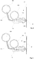
- FIG 1 is shown side projection one schematical example of prior art arrangement of spraying device for applying treatment substance on a moving fiber web W.
- the spraying device according to prior art comprises a distributor pipe 10 extending in cross direction over the width of the fiber web W.
- the distributor pipe 10 comprises several at a distance in the cross direction spaced apart from each other located nozzles 20 in one row, which nozzles 20 creating one nozzle row 21 are typically supported by a support element 15 extending in the cross direction.
- the treatment substance is supplied via channels 11 from the distributor pipe 10.
- Typical flow amount window for a nozzle in pressure range 3-12 bar is set point ⁇ 30 %.
- Typical sizing amount as dry for woodfree copy and special papers is 0.5-1.5 g/m 2 and for different board grades 1-3 g/m 2 .
- the prior art arrangement is also problematic in cases in which different substance components are used simultaneously to form the treatment substance since the substances, for example hydrophobic chemicals and color agents may react with each other or with impurities of return-flow and thus plugging may occur for example in the nozzles.
- An object of the invention is to create an arrangement in a fiber web production line and a method in a fiber web production line in which the disadvantages of known arrangements and methods relating to changes in application amounts of the treatment substance are eliminated or at least minimized.
- An object of the invention is to provide an arrangement of a fiber web production line and a method of a fiber web production line in which problems with treatment substance component reacting with each other creating plugging problems are eliminated or at least minimized.
- Further objects of the invention is to provide an arrangement of a fiber web production line and a method of a fiber web production line in which new possibilities of amount adjusting of the treatment substance and of substance component selection are available.
- the arrangement of a coating or sizing section of a fiber web production line in which section a treatment substance, in particular a coating or sizing medium, is applied onto the fiber web by spraying, which arrangement comprises nozzles located in one nozzle row extending in cross-direction i.e. in width direction of the fiber web for spraying the treatment substance onto the fiber web and at least two distributor pipes connected to the nozzles for supplying treatment substance to the nozzles in the one nozzle row and the at least two distributor pipes are each connected to alternate nozzles of the one nozzle row.
- the nozzles in the one nozzle row do not necessarily need to be on straight line and center lines of the nozzles, in particular for different distribution pipes, can be offset +/- 20 mm in the nozzle row, advantageously +/- 10 mm.
- the offset depends on distribution of the nozzles and on desired coverage of the treatment substance on the fiber web.
- the arrangement comprises two distributor pipes each connected to alternate nozzles of the one nozzle row.
- the arrangement comprises control means to selectively supply treatment substance from the distributor pipes, for example from only one distributor pipe.
- the control means are for example arranged as valves before inlet of each distributor pipe.
- the treatment substance is supplied by one machine circulation via one inlet channel and just before the inlets to the distributor pipes the inlet channel is divided to channels with valves leading to each of the inlets to the distributor pipes.
- Each distributor pipe may also have a machine circulation of its own, for example in cases where the treatment substances are not to be mixed at this stage, and thus each distribution pipe has own inlet channel, pump and optional valve. In this arrangement the inlet is controlled by the pump or by the optional valve.
- the dimensions of the distributor pipes can be same or different.
- Wet treatment substance amounts applied by nozzles of the distributor pipers vary from 5 g/m 2 to 50 g/m 2 and the speed of the fiber web depending on the production line varies from 300 m/min to 2000 m/min and the width of the fiber web from 3 m to 10 m, thus the total inlet amount of treatment substance amount to each distribution pipe varies from 10 kg/min to 1100 kg/min.
- Desired flow rate at inlet to distribution pipe varies form 2 m/s to 10 m/s and thus needed inside diameter of one distributor pipe, if only one distributor pipe is used, is from 10 mm to 80 mm and thus according to an advantageous feature the inside diameter of each distributor pipe is from 8 mm to 56 mm taking in account that the diameters of the distributor pipes can be different from each other in the arrangement according to the invention.
- the feed into each distributor pipe can be from the same or different ends of the distributor pipes.
- the outlet from each distributor pipe can be from the same or different ends of the distributor pipes. In cases where the feed to the distributor pipes is at different ends and the outlet correspondingly at different ends of the distributor pipes an inclined profile of the spayed substance amount of one distributor pipe caused by pressure loss between the ends of the distributor pipe can easily be corrected.
- outlet flow from one distributor pipe can be led to another distributor pipe and the fresh treatment substance flow to the one distributor pipe.
- the method of a coating or sizing section of a fiber web production line in which method a treatment substance, in particular a coating or sizing medium, is applied onto the fiber web by spraying by nozzles located in one nozzle row extending in cross-direction i.e. in width direction of the fiber web for spraying the treatment substance onto the fiber web, characterized in that in the method the treatment substance is supplied to the nozzles by at least two distributor pipes and in the method the treatment substance is supplied by the at least two distributor pipes, which are each connected to alternate nozzles of the one nozzle row, alternatingly to the nozzles of the one nozzle row.
- the treatment substance is supplied by two distributor pipes alternatingly to the nozzles of the one nozzle row.
- different treatment substances or components of the treatment substance can be supplied via different distributor pipes.
- substances that when reacting with each other before nozzles would cause plugging can be used by supplying one component by one distributor pipe and one component by another distributor pipe.
- the different substances or components of the substance can be for example a combination: color substance -hydrophobic substance, one color substance - another color substance, substances with different viscosity and solids content, water - chemical substance etc.
- the amount of treatment substance can be controlled without any need for changing the nozzles. Also in case the undesired plugging occurs in one distributor pipe the other one can be used.
- FIG 1 is shown side projection one schematical example of prior art arrangement of spraying device for applying treatment substance on a moving fiber web W.
- the spraying device according to prior art comprises a distributor pipe 10 extending in cross direction over the width of the fiber web W.
- the distributor pipe 10 comprises several at a distance in the cross direction spaced apart from each other located nozzles 20 in one row, which nozzles 20 creating one nozzle row 21 are typically supported by a support element 15 extending in the cross direction.
- the treatment substance is supplied from the distributor pipe 10 via channels 11.
- FIG. 2 - 3 is shown side projection one advantageous example of an arrangement of a spraying device for applying treatment substance on a moving fiber web W according to the invention.
- the spraying device comprises two distributor pipes 10A, 10B extending in cross direction over the width of the fiber web W.
- the spraying device further comprises several at a distance in the cross direction spaced apart from each other located nozzles 20A, 20B in one nozzle row 21, which nozzles 20A, 20B creating the one nozzle row 21 are supported by a support element 15 extending in the cross direction.
- the two distributor pipes 10A, 10B are alternatingly connected to the nozzles 20A, 20B for supplying treatment substance to the nozzles 20A, 20B in the one nozzle row.
- Each distributor pipe 10A, 10B are connected to alternate nozzles 20A, 20B of the one nozzle row 21.
- the treatment substance is led to nozzles 20A via channels 11A.
- Each nozzle 20A having its own channel 11A.
- the treatment substance is led to nozzles 20B via channels 11AB.
- Each nozzle 20aB having its own channel 11B.
- each distributor pipe 10A, 10B is in this example arranged from the same end of the distributor pipes 10A, 10B.
- the outlet 13A, 13B as indicated by arrows, from each distributor pipe 10A, 10B from the same of the distributor pipes 10A, 10B
- the feed 12A, 12B and correspondingly the outlet 13A, 13B of the distributor pipes 10A, 10B can also be at different ends of the distributor pipes 10A, 10B as shown by dashed arrows.
- From distributor pipes 10A, 10B via channels 11A, 11B correspondingly the treatment substance is supplied correspondingly to the alternate nozzles 20A, 20B to be sprayed onto the passing fiber web.
- FIGS 5A - 5B is very schematically, not in scale, shown examples of one nozzle row 21.
- the nozzle row comprises nozzles 20A, 20B located in the one nozzle row.
- the nozzles can be located offset O +/- 20 mm, advantageously +/- 10 mm.
- the offset O depends on distribution of the nozzles 20A, 20B i.e. the cross-directional distance between the nozzles and on desired coverage of the treatment substance on the fiber web.
- the coverage of the treatment substance spray of one nozzle is typically 300 mm on the fiber web and when the distance between two nozzles next to each other is advantageously 50 mm (i.e.
- the center lines of adjacent nozzles 20A, 20B can be located from 0 to 10 mm from the center line of adjacent nozzle 20B, 20A.
- the nozzles 20A, 20B in particular for different distribution pipes 10A, 10B, can thus be offset O +/- 10 mm in the nozzle row 21, when the distribution is 50 mm, and offset O +/- 20 mm, when the distribution is 100 mm, as shown in figures 5A and 5C .
- center lines of all nozzles 20A, 20B are in the one nozzle row 21 on same straight line.
Description
- The invention relates to an arrangement of a fiber web production line and to a method in a fiber web production line. Especially the invention relates to an arrangement and to a method of a coating or sizing section of a fiber web production line, in which section the coating or sizing medium is applied on the fiber web by spray means. More especially the invention relates to an arrangement according to the preamble part of claim 1 and to a method according to the preamble part of claim 6.
- As known from the prior art in fiber web producing processes typically comprise an assembly formed by a number of apparatuses arranged consecutively in the process line. A typical production and treatment line comprises a head box, a wire section and a press section as well as a subsequent drying section and a reel-up. The production and treatment line can further comprise other devices and sections for finishing the fiber web, for example, a sizer, a calender, a coating section. The production and treatment line typically also comprises a reel-up and at least one winder for winding customer rolls as well as at least one roll packaging apparatus. In this description and the following claims by fiber webs are meant for example paper and board webs.
- In production of fiber webs, for example of paper or board webs, sizing is used to alter the properties of a fiber web by adding sizing agents (sizing medium), for example glue chemicals. Sizing can be divided to internal sizing and surface sizing. In internal sizing the sizing agent is added to pulp in the wet end of the fiber web machine before forming. In surface sizing the sizing agent is added onto the surface of the fiber web at the dry end of the fiber web machine.
- In production of fiber webs, for example of paper or board webs, in coating, especially the surface of a fiber web is formed with a layer of coating color (coating medium) at a coating station followed by drying. The formation of a coating in direct coating applications can be divided in supplying the coating color onto the web surface, which is called the application of the coating color, as well as in the adjustment of final amount of coating color. In indirect coating applications the adjustment of the color amount is controlled already when supplying the color and therefore an additional adjustment is not needed.
- The coating or the sizing of a fiber web typically utilizes a coating device - a coater - or a sizing device - a sizer, which together with for example drying devices following the coater/sizer form the coating / sizing section of a fiber web production line. In connection with the coaters and sizers different kinds of application technology for application of the coating or the sizing medium on the fiber web are employed in prior art arrangements, for example curtain technology or blade application technology or rod application technology or air brush application technology or spray application technology. The present invention relates to spray application technology.
- In
WO publication 2006/058961 A1 is disclosed a method and arrangement for processing a paper or board web or similar fiber web. In this prior art method a processing mixture is applied on the surface of the web with spray nozzles. InWO publication 02/072953 - In
US 2005/098291 is disclosed an apparatus for paper making and paper surface enhancement, in which nozzles are located in several rows in cross-direction i.e. in width direction of the paper web. -
US 2003/120303 discloses a distribution pipe structure from steel industry, in which the pipes are located within each other and the innermost pipe is for glue and in the two outer pipes there is water for controlling the temperature of the glue and for cleaning the nozzles. - In
US 2007/029411 is disclosed an air atomizing nozzle system for medical industry in which substance is distributed to all nozzles by one pipe. -
US 2118212 discloses a process and apparatus for coating paper in which several rows of nozzles are used. - The coating and sizing units can be located in different positions in the fiber web production line, for example at a wire section, or at a press section, or at a drying section comprising drying cylinders. However, the typical location is after the pre-dryer section, when the web moisture is typically between 2-12 %. The nozzles or nozzle units of a spray coating or sizing unit are as known from prior art attached to a distributor pipe that extends in cross direction over the width of the fiber web and that delivers the treatment substance to the nozzles. In
figure 1 is shown side projection one schematical example of prior art arrangement of spraying device for applying treatment substance on a moving fiber web W. The spraying device according to prior art comprises a distributor pipe 10 extending in cross direction over the width of the fiber web W. The distributor pipe 10 comprises several at a distance in the cross direction spaced apart from each other locatednozzles 20 in one row, which nozzles 20 creating onenozzle row 21 are typically supported by asupport element 15 extending in the cross direction. Into allnozzles 20 of thenozzle row 21 the treatment substance is supplied viachannels 11 from the distributor pipe 10. In this prior art arrangement large changes in application amounts of the treatment substance to be sprayed onto the fiber web W via the nozzles have not been possible without changing the nozzles or without using several successive nozzle rows in the running direction of the web. Typical flow amount window for a nozzle in pressure range 3-12 bar is set point ± 30 %. Typical sizing amount as dry for woodfree copy and special papers is 0.5-1.5 g/m2 and for different board grades 1-3 g/m2. The prior art arrangement is also problematic in cases in which different substance components are used simultaneously to form the treatment substance since the substances, for example hydrophobic chemicals and color agents may react with each other or with impurities of return-flow and thus plugging may occur for example in the nozzles. - An object of the invention is to create an arrangement in a fiber web production line and a method in a fiber web production line in which the disadvantages of known arrangements and methods relating to changes in application amounts of the treatment substance are eliminated or at least minimized.
- An object of the invention is to provide an arrangement of a fiber web production line and a method of a fiber web production line in which problems with treatment substance component reacting with each other creating plugging problems are eliminated or at least minimized.
- Further objects of the invention is to provide an arrangement of a fiber web production line and a method of a fiber web production line in which new possibilities of amount adjusting of the treatment substance and of substance component selection are available.
- In order to achieve the above objects the arrangement according to the invention is mainly characterized by the features of claim 1 and the method according to the invention is mainly characterized by the features of claim 6.
- According to an advantageous aspect of the invention the arrangement of a coating or sizing section of a fiber web production line, in which section a treatment substance, in particular a coating or sizing medium, is applied onto the fiber web by spraying, which arrangement comprises nozzles located in one nozzle row extending in cross-direction i.e. in width direction of the fiber web for spraying the treatment substance onto the fiber web and at least two distributor pipes connected to the nozzles for supplying treatment substance to the nozzles in the one nozzle row and the at least two distributor pipes are each connected to alternate nozzles of the one nozzle row.
- The nozzles in the one nozzle row do not necessarily need to be on straight line and center lines of the nozzles, in particular for different distribution pipes, can be offset +/- 20 mm in the nozzle row, advantageously +/- 10 mm. The offset depends on distribution of the nozzles and on desired coverage of the treatment substance on the fiber web.
- Advantageously the arrangement comprises two distributor pipes each connected to alternate nozzles of the one nozzle row.
- Advantageously the arrangement comprises control means to selectively supply treatment substance from the distributor pipes, for example from only one distributor pipe. The control means are for example arranged as valves before inlet of each distributor pipe. The treatment substance is supplied by one machine circulation via one inlet channel and just before the inlets to the distributor pipes the inlet channel is divided to channels with valves leading to each of the inlets to the distributor pipes. Each distributor pipe may also have a machine circulation of its own, for example in cases where the treatment substances are not to be mixed at this stage, and thus each distribution pipe has own inlet channel, pump and optional valve. In this arrangement the inlet is controlled by the pump or by the optional valve.
- The dimensions of the distributor pipes can be same or different. Wet treatment substance amounts applied by nozzles of the distributor pipers vary from 5 g/m2 to 50 g/m2 and the speed of the fiber web depending on the production line varies from 300 m/min to 2000 m/min and the width of the fiber web from 3 m to 10 m, thus the total inlet amount of treatment substance amount to each distribution pipe varies from 10 kg/min to 1100 kg/min. Desired flow rate at inlet to distribution pipe varies form 2 m/s to 10 m/s and thus needed inside diameter of one distributor pipe, if only one distributor pipe is used, is from 10 mm to 80 mm and thus according to an advantageous feature the inside diameter of each distributor pipe is from 8 mm to 56 mm taking in account that the diameters of the distributor pipes can be different from each other in the arrangement according to the invention.
- The feed into each distributor pipe can be from the same or different ends of the distributor pipes. The outlet from each distributor pipe can be from the same or different ends of the distributor pipes. In cases where the feed to the distributor pipes is at different ends and the outlet correspondingly at different ends of the distributor pipes an inclined profile of the spayed substance amount of one distributor pipe caused by pressure loss between the ends of the distributor pipe can easily be corrected.
- According to one advantageous feature the outlet flow from one distributor pipe can be led to another distributor pipe and the fresh treatment substance flow to the one distributor pipe.
- According to the invention the method of a coating or sizing section of a fiber web production line, in which method a treatment substance, in particular a coating or sizing medium, is applied onto the fiber web by spraying by nozzles located in one nozzle row extending in cross-direction i.e. in width direction of the fiber web for spraying the treatment substance onto the fiber web, characterized in that in the method the treatment substance is supplied to the nozzles by at least two distributor pipes and in the method the treatment substance is supplied by the at least two distributor pipes, which are each connected to alternate nozzles of the one nozzle row, alternatingly to the nozzles of the one nozzle row.
- Advantageously in the method the treatment substance is supplied by two distributor pipes alternatingly to the nozzles of the one nozzle row.
- According to an advantageous feature of the invention different treatment substances or components of the treatment substance can be supplied via different distributor pipes. By this it is possible to use substances that when reacting with each other before nozzles would cause plugging. Furthermore two-component substances can be used by supplying one component by one distributor pipe and one component by another distributor pipe. The different substances or components of the substance can be for example a combination: color substance -hydrophobic substance, one color substance - another color substance, substances with different viscosity and solids content, water - chemical substance etc.
- By the invention the amount of treatment substance can be controlled without any need for changing the nozzles. Also in case the undesired plugging occurs in one distributor pipe the other one can be used.
- In the following the invention is explained in more detail with reference to the accompanying drawing in which
-
Figure 1 shows as side projection one schematical example of prior art. -
Figures 2 - 3 show as side projection schematically one advantageous example of the invention. -
Figure 4 shows as a longitudinal view in the width direction of a fiber web schematically one advantageous example of the invention. -
Figures 5A - 5B show very schematically examples of one nozzle row. - In the figures the corresponding elements, parts and part components of the arrangement are denoted by same reference signs in the figures unless otherwise mentioned.
- In
figure 1 is shown side projection one schematical example of prior art arrangement of spraying device for applying treatment substance on a moving fiber web W. The spraying device according to prior art comprises a distributor pipe 10 extending in cross direction over the width of the fiber web W. The distributor pipe 10 comprises several at a distance in the cross direction spaced apart from each other locatednozzles 20 in one row, which nozzles 20 creating onenozzle row 21 are typically supported by asupport element 15 extending in the cross direction. Into allnozzles 20 of thenozzle row 21 the treatment substance is supplied from the distributor pipe 10 viachannels 11. - In
figures 2 - 3 is shown side projection one advantageous example of an arrangement of a spraying device for applying treatment substance on a moving fiber web W according to the invention. The spraying device comprises twodistributor pipes nozzles nozzle row 21, which nozzles 20A, 20B creating the onenozzle row 21 are supported by asupport element 15 extending in the cross direction. The twodistributor pipes nozzles nozzles distributor pipe alternate nozzles nozzle row 21. As shown infigure 2 fromdistributor pipe 10A the treatment substance is led tonozzles 20A viachannels 11A. Eachnozzle 20A having itsown channel 11A. As shown infigure 3 fromdistributor pipe 10B the treatment substance is led tonozzles 20B via channels 11AB. Each nozzle 20aB having itsown channel 11B. - As shown in
figure 4 , where feeds and outlets are indicated by arrows, thefeed distributor pipe distributor pipes outlet distributor pipe distributor pipes feed outlet distributor pipes distributor pipes distributor pipes channels alternate nozzles - In
figures 5A - 5B is very schematically, not in scale, shown examples of onenozzle row 21. The nozzle row comprisesnozzles nozzles adjacent nozzles adjacent nozzles adjacent nozzle nozzles different distribution pipes nozzle row 21, when the distribution is 50 mm, and offset O +/- 20 mm, when the distribution is 100 mm, as shown infigures 5A and5C . In the example offigure 5B center lines of allnozzles nozzle row 21 on same straight line. -
- 10, 10A, 10B distribution pipe
- 11, 11A, 11B channel from distribution pipe to nozzle
- 12A, 12B inlet to distribution pipe
- 13A, 13B outlet from distribution pipe
- 15 support element
- 20, 20A, 20B nozzle
- 21 nozzle row
- W web
- O offset
Claims (10)
- Arrangement in of a coating or sizing section of a fiber web production line, in which section a treatment substance, in particular a coating or sizing medium, is applied onto the fiber web by spraying, which arrangement comprises nozzles (20A, 20B) located in one nozzle row (21) extending in cross-direction i.e. in width direction of the fiber web for spraying the treatment substance onto the fiber web, characterized in that the arrangement comprises at least two distributor pipes (10A, 10B) connected to the nozzles (20A, 20B) for supplying treatment substance to the nozzles (20A, 20B) in the one nozzle row (21) and that in the arrangement the at least two distributor pipes (10A, 10B) are each connected to alternate nozzles (20A, 20B) of the one nozzle row (21).
- Arrangement according to claim 1, characterized in that the center lines of the nozzles (20A, 20B), in particular for different distribution pipes (10A, 10B), are offset (O) +/- 20 mm, advantageously +/- 10 mm in the one nozzle row (21).
- Arrangement according to any of claims 1 or 2, characterized in that the arrangement comprises two distributor pipes (10A, 10B) each connected to alternate nozzles (20A, 20B) of the one nozzle row (21).
- Arrangement according to any of claims 1 - 3, characterized in that the arrangement comprises control means to selectively supply treatment substance from the distributor pipes (10A, 10B).
- Arrangement according to any of claims 1 - 4, characterized in that inside diameter of each distributor pipe (10A; 10B) is from 8 mm to 56 mm.
- Method for a coating or sizing section of a fiber web production line, in which method a treatment substance, in particular a coating or sizing medium, is applied onto the fiber web by spraying by nozzles (20A, 20B) located in one nozzle row (21) extending in cross-direction i.e. in width direction of the fiber web for spraying the treatment substance onto the fiber web, characterized in that in the method the treatment substance is supplied to the nozzles (20A, 20B) in the one nozzle row by at least two distributor pipes (10A, 10B), and that in the method the treatment substance is supplied by the at least two distributor pipes (10A, 10B), which are each connected to alternate nozzles (20A, 20B) of the one nozzle row (21), alternatingly to the nozzles (20A, 20B) of the one nozzle row (21).
- Method according to claim 6, characterized in that in the method the treatment substance is supplied by two distributor pipes (10A, 10B) alternatingly to the nozzles (20A, 20B) of the one nozzle row (21).
- Method according to claim 6, characterized in that in the method different treatment substances or components of the treatment substance are be supplied via different distributor pipes (10A, 10B).
- Method according to claim 8, characterized in that in the method different substances or components of the substance are selected from the combinations: color substance -hydrophobic substance, one color substance - another color substance, substances with different viscosity and solids content.
- Method according to claim 6, characterized in that in the method different amount of the treatment substance is supplied by different distributor pipes (10A, 10B).
Priority Applications (2)
| Application Number | Priority Date | Filing Date | Title |
|---|---|---|---|
| EP13187694.8A EP2860312B1 (en) | 2013-10-08 | 2013-10-08 | Arrangement of a fiber web production line and method of a fiber web production line |
| CN201420546976.4U CN204238070U (en) | 2013-10-08 | 2014-09-23 | The layout of fibrous-web manufacturing line |
Applications Claiming Priority (1)
| Application Number | Priority Date | Filing Date | Title |
|---|---|---|---|
| EP13187694.8A EP2860312B1 (en) | 2013-10-08 | 2013-10-08 | Arrangement of a fiber web production line and method of a fiber web production line |
Publications (2)
| Publication Number | Publication Date |
|---|---|
| EP2860312A1 EP2860312A1 (en) | 2015-04-15 |
| EP2860312B1 true EP2860312B1 (en) | 2019-05-22 |
Family
ID=49301389
Family Applications (1)
| Application Number | Title | Priority Date | Filing Date |
|---|---|---|---|
| EP13187694.8A Active EP2860312B1 (en) | 2013-10-08 | 2013-10-08 | Arrangement of a fiber web production line and method of a fiber web production line |
Country Status (2)
| Country | Link |
|---|---|
| EP (1) | EP2860312B1 (en) |
| CN (1) | CN204238070U (en) |
Families Citing this family (2)
| Publication number | Priority date | Publication date | Assignee | Title |
|---|---|---|---|---|
| JP6553320B1 (en) * | 2017-12-28 | 2019-07-31 | コアレックス信栄株式会社 | Deodorant paper manufacturing method |
| EP3910103A1 (en) * | 2020-05-15 | 2021-11-17 | Valmet Technologies Oy | Method and system for applying a substance layer onto a moving fiber web by foam application |
Family Cites Families (10)
| Publication number | Priority date | Publication date | Assignee | Title |
|---|---|---|---|---|
| US2118212A (en) * | 1933-04-24 | 1938-05-24 | James D Maclaurin | Process and apparatus for coating paper |
| FI108061B (en) * | 1995-10-05 | 2001-11-15 | Metso Paper Inc | Method for coating a paper or cardboard web |
| US6755913B1 (en) * | 1999-02-15 | 2004-06-29 | Nordson Corporation | Multi-color change device with conductive coating material for electrostatic coating |
| FI115314B (en) | 2001-03-13 | 2005-04-15 | Metso Paper Inc | Arrangement for handling paper or cardboard |
| US20030129303A1 (en) * | 2002-01-08 | 2003-07-10 | Borwig Michael C. | Apparatus and method for applying glue |
| FI115408B (en) * | 2002-01-31 | 2005-04-29 | Ciba Sc Holding Ag | Method for Coating Paper or Cardboard, Use of the Method and Coating Paste |
| US7217342B2 (en) * | 2002-11-25 | 2007-05-15 | Kangas Martti Y O | Apparatus for paper making and paper surface enhancement |
| US7837131B2 (en) * | 2003-03-27 | 2010-11-23 | Spraying Systems Co. | Modular automatic spray gun manifold |
| FI121084B (en) | 2004-12-01 | 2010-06-30 | Metso Paper Inc | Method and arrangement for treating a fiber web |
| JP5787700B2 (en) * | 2011-09-30 | 2015-09-30 | ユニ・チャーム株式会社 | Nonwoven manufacturing method |
-
2013
- 2013-10-08 EP EP13187694.8A patent/EP2860312B1/en active Active
-
2014
- 2014-09-23 CN CN201420546976.4U patent/CN204238070U/en active Active
Non-Patent Citations (1)
| Title |
|---|
| None * |
Also Published As
| Publication number | Publication date |
|---|---|
| EP2860312A1 (en) | 2015-04-15 |
| CN204238070U (en) | 2015-04-01 |
Similar Documents
| Publication | Publication Date | Title |
|---|---|---|
| EP1123665B1 (en) | Cigarette paper | |
| JP4500046B2 (en) | Method and apparatus for applying material to a web | |
| US8425721B2 (en) | Method and apparatus for treating a fibrous web | |
| FI96894C (en) | Method and apparatus for coating paper or the like | |
| EP2811069B1 (en) | Device for treating a fiber web | |
| AU2002326975A1 (en) | Method and apparatus for applying a material to a web | |
| CN113089369B (en) | Device for applying a treatment substance | |
| EP3096887A2 (en) | Nozzle assembly with self-cleaning face | |
| EP2860312B1 (en) | Arrangement of a fiber web production line and method of a fiber web production line | |
| EP2868802A1 (en) | Arrangement of a fiber web production line and method of a fiber web production line | |
| FI126292B (en) | DEVICE FOR PROCESSING FIBERS | |
| US8152968B2 (en) | Machine for the production of a fibrous web | |
| AT519414B1 (en) | METHOD AND SYSTEM FOR THE APPLICATION OF A SUBSTANCE LAYER ON A MOVING FIBERWAY THROUGH THE FOAM PROCESSING | |
| EP2808087B1 (en) | Device for treating a fibre web | |
| DE102009009862B4 (en) | Method and installation for applying a suspension to a material web | |
| US20030024672A1 (en) | Method and arrangement for processing a wide paper or board web | |
| US20170370644A1 (en) | Nozzle of a Device for Contact - Free Treatment of a Running Fiber Web | |
| EP2894254B1 (en) | Coating device for applying coating color onto a fiber web and method for coating of a fiber web | |
| FI12411U1 (en) | Device for manufacturing a surface sizing agent for a fibre web | |
| EP2647761A1 (en) | Method for influencing the hydrophobic properties of a fiber web in connection with production of the fiber web and production process for fiber webs and device for application of hydrophobic glue chemical to the fiber web | |
| US20030113455A1 (en) | Apparatus and method for controlling the curling or paper or paperboard | |
| WO2012095553A2 (en) | Spray apparatus and spray method for fiber web | |
| EP4245916A1 (en) | Method of treating a fiber web and a treatment system for treatment of a fiber web | |
| FI128140B (en) | System for changing a nozzle pipe of an application device of a fiber web production line | |
| US6406751B1 (en) | Apparatus and a process for preventing stalagmite formation in the paper coating operation |
Legal Events
| Date | Code | Title | Description |
|---|---|---|---|
| PUAI | Public reference made under article 153(3) epc to a published international application that has entered the european phase |
Free format text: ORIGINAL CODE: 0009012 |
|
| 17P | Request for examination filed |
Effective date: 20131008 |
|
| AK | Designated contracting states |
Kind code of ref document: A1 Designated state(s): AL AT BE BG CH CY CZ DE DK EE ES FI FR GB GR HR HU IE IS IT LI LT LU LV MC MK MT NL NO PL PT RO RS SE SI SK SM TR |
|
| AX | Request for extension of the european patent |
Extension state: BA ME |
|
| R17P | Request for examination filed (corrected) |
Effective date: 20150916 |
|
| RBV | Designated contracting states (corrected) |
Designated state(s): AL AT BE BG CH CY CZ DE DK EE ES FI FR GB GR HR HU IE IS IT LI LT LU LV MC MK MT NL NO PL PT RO RS SE SI SK SM TR |
|
| STAA | Information on the status of an ep patent application or granted ep patent |
Free format text: STATUS: EXAMINATION IS IN PROGRESS |
|
| 17Q | First examination report despatched |
Effective date: 20180423 |
|
| GRAP | Despatch of communication of intention to grant a patent |
Free format text: ORIGINAL CODE: EPIDOSNIGR1 |
|
| STAA | Information on the status of an ep patent application or granted ep patent |
Free format text: STATUS: GRANT OF PATENT IS INTENDED |
|
| INTG | Intention to grant announced |
Effective date: 20190107 |
|
| GRAS | Grant fee paid |
Free format text: ORIGINAL CODE: EPIDOSNIGR3 |
|
| GRAA | (expected) grant |
Free format text: ORIGINAL CODE: 0009210 |
|
| STAA | Information on the status of an ep patent application or granted ep patent |
Free format text: STATUS: THE PATENT HAS BEEN GRANTED |
|
| AK | Designated contracting states |
Kind code of ref document: B1 Designated state(s): AL AT BE BG CH CY CZ DE DK EE ES FI FR GB GR HR HU IE IS IT LI LT LU LV MC MK MT NL NO PL PT RO RS SE SI SK SM TR |
|
| REG | Reference to a national code |
Ref country code: GB Ref legal event code: FG4D |
|
| REG | Reference to a national code |
Ref country code: CH Ref legal event code: EP |
|
| REG | Reference to a national code |
Ref country code: IE Ref legal event code: FG4D |
|
| REG | Reference to a national code |
Ref country code: AT Ref legal event code: REF Ref document number: 1136261 Country of ref document: AT Kind code of ref document: T Effective date: 20190615 |
|
| REG | Reference to a national code |
Ref country code: DE Ref legal event code: R096 Ref document number: 602013055684 Country of ref document: DE |
|
| REG | Reference to a national code |
Ref country code: NL Ref legal event code: MP Effective date: 20190522 |
|
| REG | Reference to a national code |
Ref country code: LT Ref legal event code: MG4D |
|
| PG25 | Lapsed in a contracting state [announced via postgrant information from national office to epo] |
Ref country code: NO Free format text: LAPSE BECAUSE OF FAILURE TO SUBMIT A TRANSLATION OF THE DESCRIPTION OR TO PAY THE FEE WITHIN THE PRESCRIBED TIME-LIMIT Effective date: 20190822 Ref country code: HR Free format text: LAPSE BECAUSE OF FAILURE TO SUBMIT A TRANSLATION OF THE DESCRIPTION OR TO PAY THE FEE WITHIN THE PRESCRIBED TIME-LIMIT Effective date: 20190522 Ref country code: NL Free format text: LAPSE BECAUSE OF FAILURE TO SUBMIT A TRANSLATION OF THE DESCRIPTION OR TO PAY THE FEE WITHIN THE PRESCRIBED TIME-LIMIT Effective date: 20190522 Ref country code: ES Free format text: LAPSE BECAUSE OF FAILURE TO SUBMIT A TRANSLATION OF THE DESCRIPTION OR TO PAY THE FEE WITHIN THE PRESCRIBED TIME-LIMIT Effective date: 20190522 Ref country code: LT Free format text: LAPSE BECAUSE OF FAILURE TO SUBMIT A TRANSLATION OF THE DESCRIPTION OR TO PAY THE FEE WITHIN THE PRESCRIBED TIME-LIMIT Effective date: 20190522 Ref country code: AL Free format text: LAPSE BECAUSE OF FAILURE TO SUBMIT A TRANSLATION OF THE DESCRIPTION OR TO PAY THE FEE WITHIN THE PRESCRIBED TIME-LIMIT Effective date: 20190522 Ref country code: PT Free format text: LAPSE BECAUSE OF FAILURE TO SUBMIT A TRANSLATION OF THE DESCRIPTION OR TO PAY THE FEE WITHIN THE PRESCRIBED TIME-LIMIT Effective date: 20190922 Ref country code: SE Free format text: LAPSE BECAUSE OF FAILURE TO SUBMIT A TRANSLATION OF THE DESCRIPTION OR TO PAY THE FEE WITHIN THE PRESCRIBED TIME-LIMIT Effective date: 20190522 Ref country code: FI Free format text: LAPSE BECAUSE OF FAILURE TO SUBMIT A TRANSLATION OF THE DESCRIPTION OR TO PAY THE FEE WITHIN THE PRESCRIBED TIME-LIMIT Effective date: 20190522 |
|
| PG25 | Lapsed in a contracting state [announced via postgrant information from national office to epo] |
Ref country code: BG Free format text: LAPSE BECAUSE OF FAILURE TO SUBMIT A TRANSLATION OF THE DESCRIPTION OR TO PAY THE FEE WITHIN THE PRESCRIBED TIME-LIMIT Effective date: 20190822 Ref country code: GR Free format text: LAPSE BECAUSE OF FAILURE TO SUBMIT A TRANSLATION OF THE DESCRIPTION OR TO PAY THE FEE WITHIN THE PRESCRIBED TIME-LIMIT Effective date: 20190823 Ref country code: LV Free format text: LAPSE BECAUSE OF FAILURE TO SUBMIT A TRANSLATION OF THE DESCRIPTION OR TO PAY THE FEE WITHIN THE PRESCRIBED TIME-LIMIT Effective date: 20190522 Ref country code: RS Free format text: LAPSE BECAUSE OF FAILURE TO SUBMIT A TRANSLATION OF THE DESCRIPTION OR TO PAY THE FEE WITHIN THE PRESCRIBED TIME-LIMIT Effective date: 20190522 |
|
| REG | Reference to a national code |
Ref country code: AT Ref legal event code: MK05 Ref document number: 1136261 Country of ref document: AT Kind code of ref document: T Effective date: 20190522 |
|
| PG25 | Lapsed in a contracting state [announced via postgrant information from national office to epo] |
Ref country code: SK Free format text: LAPSE BECAUSE OF FAILURE TO SUBMIT A TRANSLATION OF THE DESCRIPTION OR TO PAY THE FEE WITHIN THE PRESCRIBED TIME-LIMIT Effective date: 20190522 Ref country code: CZ Free format text: LAPSE BECAUSE OF FAILURE TO SUBMIT A TRANSLATION OF THE DESCRIPTION OR TO PAY THE FEE WITHIN THE PRESCRIBED TIME-LIMIT Effective date: 20190522 Ref country code: AT Free format text: LAPSE BECAUSE OF FAILURE TO SUBMIT A TRANSLATION OF THE DESCRIPTION OR TO PAY THE FEE WITHIN THE PRESCRIBED TIME-LIMIT Effective date: 20190522 Ref country code: RO Free format text: LAPSE BECAUSE OF FAILURE TO SUBMIT A TRANSLATION OF THE DESCRIPTION OR TO PAY THE FEE WITHIN THE PRESCRIBED TIME-LIMIT Effective date: 20190522 Ref country code: DK Free format text: LAPSE BECAUSE OF FAILURE TO SUBMIT A TRANSLATION OF THE DESCRIPTION OR TO PAY THE FEE WITHIN THE PRESCRIBED TIME-LIMIT Effective date: 20190522 Ref country code: EE Free format text: LAPSE BECAUSE OF FAILURE TO SUBMIT A TRANSLATION OF THE DESCRIPTION OR TO PAY THE FEE WITHIN THE PRESCRIBED TIME-LIMIT Effective date: 20190522 |
|
| REG | Reference to a national code |
Ref country code: DE Ref legal event code: R097 Ref document number: 602013055684 Country of ref document: DE |
|
| PG25 | Lapsed in a contracting state [announced via postgrant information from national office to epo] |
Ref country code: SM Free format text: LAPSE BECAUSE OF FAILURE TO SUBMIT A TRANSLATION OF THE DESCRIPTION OR TO PAY THE FEE WITHIN THE PRESCRIBED TIME-LIMIT Effective date: 20190522 Ref country code: IT Free format text: LAPSE BECAUSE OF FAILURE TO SUBMIT A TRANSLATION OF THE DESCRIPTION OR TO PAY THE FEE WITHIN THE PRESCRIBED TIME-LIMIT Effective date: 20190522 |
|
| PLBE | No opposition filed within time limit |
Free format text: ORIGINAL CODE: 0009261 |
|
| STAA | Information on the status of an ep patent application or granted ep patent |
Free format text: STATUS: NO OPPOSITION FILED WITHIN TIME LIMIT |
|
| PG25 | Lapsed in a contracting state [announced via postgrant information from national office to epo] |
Ref country code: TR Free format text: LAPSE BECAUSE OF FAILURE TO SUBMIT A TRANSLATION OF THE DESCRIPTION OR TO PAY THE FEE WITHIN THE PRESCRIBED TIME-LIMIT Effective date: 20190522 |
|
| 26N | No opposition filed |
Effective date: 20200225 |
|
| PG25 | Lapsed in a contracting state [announced via postgrant information from national office to epo] |
Ref country code: PL Free format text: LAPSE BECAUSE OF FAILURE TO SUBMIT A TRANSLATION OF THE DESCRIPTION OR TO PAY THE FEE WITHIN THE PRESCRIBED TIME-LIMIT Effective date: 20190522 |
|
| PG25 | Lapsed in a contracting state [announced via postgrant information from national office to epo] |
Ref country code: MC Free format text: LAPSE BECAUSE OF FAILURE TO SUBMIT A TRANSLATION OF THE DESCRIPTION OR TO PAY THE FEE WITHIN THE PRESCRIBED TIME-LIMIT Effective date: 20190522 Ref country code: SI Free format text: LAPSE BECAUSE OF FAILURE TO SUBMIT A TRANSLATION OF THE DESCRIPTION OR TO PAY THE FEE WITHIN THE PRESCRIBED TIME-LIMIT Effective date: 20190522 |
|
| REG | Reference to a national code |
Ref country code: CH Ref legal event code: PL |
|
| PG25 | Lapsed in a contracting state [announced via postgrant information from national office to epo] |
Ref country code: CH Free format text: LAPSE BECAUSE OF NON-PAYMENT OF DUE FEES Effective date: 20191031 Ref country code: LI Free format text: LAPSE BECAUSE OF NON-PAYMENT OF DUE FEES Effective date: 20191031 Ref country code: LU Free format text: LAPSE BECAUSE OF NON-PAYMENT OF DUE FEES Effective date: 20191008 |
|
| REG | Reference to a national code |
Ref country code: BE Ref legal event code: MM Effective date: 20191031 |
|
| PG25 | Lapsed in a contracting state [announced via postgrant information from national office to epo] |
Ref country code: BE Free format text: LAPSE BECAUSE OF NON-PAYMENT OF DUE FEES Effective date: 20191031 |
|
| GBPC | Gb: european patent ceased through non-payment of renewal fee |
Effective date: 20191008 |
|
| PG25 | Lapsed in a contracting state [announced via postgrant information from national office to epo] |
Ref country code: IE Free format text: LAPSE BECAUSE OF NON-PAYMENT OF DUE FEES Effective date: 20191008 Ref country code: FR Free format text: LAPSE BECAUSE OF NON-PAYMENT OF DUE FEES Effective date: 20191031 Ref country code: GB Free format text: LAPSE BECAUSE OF NON-PAYMENT OF DUE FEES Effective date: 20191008 |
|
| PG25 | Lapsed in a contracting state [announced via postgrant information from national office to epo] |
Ref country code: CY Free format text: LAPSE BECAUSE OF FAILURE TO SUBMIT A TRANSLATION OF THE DESCRIPTION OR TO PAY THE FEE WITHIN THE PRESCRIBED TIME-LIMIT Effective date: 20190522 |
|
| PG25 | Lapsed in a contracting state [announced via postgrant information from national office to epo] |
Ref country code: IS Free format text: LAPSE BECAUSE OF FAILURE TO SUBMIT A TRANSLATION OF THE DESCRIPTION OR TO PAY THE FEE WITHIN THE PRESCRIBED TIME-LIMIT Effective date: 20190922 |
|
| PG25 | Lapsed in a contracting state [announced via postgrant information from national office to epo] |
Ref country code: MT Free format text: LAPSE BECAUSE OF FAILURE TO SUBMIT A TRANSLATION OF THE DESCRIPTION OR TO PAY THE FEE WITHIN THE PRESCRIBED TIME-LIMIT Effective date: 20190522 Ref country code: HU Free format text: LAPSE BECAUSE OF FAILURE TO SUBMIT A TRANSLATION OF THE DESCRIPTION OR TO PAY THE FEE WITHIN THE PRESCRIBED TIME-LIMIT; INVALID AB INITIO Effective date: 20131008 |
|
| PG25 | Lapsed in a contracting state [announced via postgrant information from national office to epo] |
Ref country code: MK Free format text: LAPSE BECAUSE OF FAILURE TO SUBMIT A TRANSLATION OF THE DESCRIPTION OR TO PAY THE FEE WITHIN THE PRESCRIBED TIME-LIMIT Effective date: 20190522 |
|
| PGFP | Annual fee paid to national office [announced via postgrant information from national office to epo] |
Ref country code: DE Payment date: 20221019 Year of fee payment: 10 |