US7021608B2 - Distributor for micro-quantities of liquid - Google Patents
Distributor for micro-quantities of liquid Download PDFInfo
- Publication number
- US7021608B2 US7021608B2 US10/486,822 US48682204A US7021608B2 US 7021608 B2 US7021608 B2 US 7021608B2 US 48682204 A US48682204 A US 48682204A US 7021608 B2 US7021608 B2 US 7021608B2
- Authority
- US
- United States
- Prior art keywords
- liquid
- ultra low
- low flow
- accordance
- distributor
- Prior art date
- Legal status (The legal status is an assumption and is not a legal conclusion. Google has not performed a legal analysis and makes no representation as to the accuracy of the status listed.)
- Expired - Fee Related, expires
Links
Images


Classifications
-
- F—MECHANICAL ENGINEERING; LIGHTING; HEATING; WEAPONS; BLASTING
- F28—HEAT EXCHANGE IN GENERAL
- F28F—DETAILS OF HEAT-EXCHANGE AND HEAT-TRANSFER APPARATUS, OF GENERAL APPLICATION
- F28F9/00—Casings; Header boxes; Auxiliary supports for elements; Auxiliary members within casings
- F28F9/02—Header boxes; End plates
- F28F9/026—Header boxes; End plates with static flow control means, e.g. with means for uniformly distributing heat exchange media into conduits
- F28F9/027—Header boxes; End plates with static flow control means, e.g. with means for uniformly distributing heat exchange media into conduits in the form of distribution pipes
- F28F9/0275—Header boxes; End plates with static flow control means, e.g. with means for uniformly distributing heat exchange media into conduits in the form of distribution pipes with multiple branch pipes
-
- B—PERFORMING OPERATIONS; TRANSPORTING
- B01—PHYSICAL OR CHEMICAL PROCESSES OR APPARATUS IN GENERAL
- B01D—SEPARATION
- B01D3/00—Distillation or related exchange processes in which liquids are contacted with gaseous media, e.g. stripping
- B01D3/008—Liquid distribution
-
- B—PERFORMING OPERATIONS; TRANSPORTING
- B01—PHYSICAL OR CHEMICAL PROCESSES OR APPARATUS IN GENERAL
- B01J—CHEMICAL OR PHYSICAL PROCESSES, e.g. CATALYSIS OR COLLOID CHEMISTRY; THEIR RELEVANT APPARATUS
- B01J19/00—Chemical, physical or physico-chemical processes in general; Their relevant apparatus
- B01J19/0093—Microreactors, e.g. miniaturised or microfabricated reactors
-
- B—PERFORMING OPERATIONS; TRANSPORTING
- B01—PHYSICAL OR CHEMICAL PROCESSES OR APPARATUS IN GENERAL
- B01J—CHEMICAL OR PHYSICAL PROCESSES, e.g. CATALYSIS OR COLLOID CHEMISTRY; THEIR RELEVANT APPARATUS
- B01J19/00—Chemical, physical or physico-chemical processes in general; Their relevant apparatus
- B01J19/24—Stationary reactors without moving elements inside
- B01J19/247—Suited for forming thin films
-
- B—PERFORMING OPERATIONS; TRANSPORTING
- B01—PHYSICAL OR CHEMICAL PROCESSES OR APPARATUS IN GENERAL
- B01J—CHEMICAL OR PHYSICAL PROCESSES, e.g. CATALYSIS OR COLLOID CHEMISTRY; THEIR RELEVANT APPARATUS
- B01J19/00—Chemical, physical or physico-chemical processes in general; Their relevant apparatus
- B01J19/24—Stationary reactors without moving elements inside
- B01J19/248—Reactors comprising multiple separated flow channels
- B01J19/249—Plate-type reactors
-
- F—MECHANICAL ENGINEERING; LIGHTING; HEATING; WEAPONS; BLASTING
- F24—HEATING; RANGES; VENTILATING
- F24F—AIR-CONDITIONING; AIR-HUMIDIFICATION; VENTILATION; USE OF AIR CURRENTS FOR SCREENING
- F24F3/00—Air-conditioning systems in which conditioned primary air is supplied from one or more central stations to distributing units in the rooms or spaces where it may receive secondary treatment; Apparatus specially designed for such systems
- F24F3/12—Air-conditioning systems in which conditioned primary air is supplied from one or more central stations to distributing units in the rooms or spaces where it may receive secondary treatment; Apparatus specially designed for such systems characterised by the treatment of the air otherwise than by heating and cooling
- F24F3/14—Air-conditioning systems in which conditioned primary air is supplied from one or more central stations to distributing units in the rooms or spaces where it may receive secondary treatment; Apparatus specially designed for such systems characterised by the treatment of the air otherwise than by heating and cooling by humidification; by dehumidification
- F24F3/1411—Air-conditioning systems in which conditioned primary air is supplied from one or more central stations to distributing units in the rooms or spaces where it may receive secondary treatment; Apparatus specially designed for such systems characterised by the treatment of the air otherwise than by heating and cooling by humidification; by dehumidification by absorbing or adsorbing water, e.g. using an hygroscopic desiccant
-
- F—MECHANICAL ENGINEERING; LIGHTING; HEATING; WEAPONS; BLASTING
- F28—HEAT EXCHANGE IN GENERAL
- F28D—HEAT-EXCHANGE APPARATUS, NOT PROVIDED FOR IN ANOTHER SUBCLASS, IN WHICH THE HEAT-EXCHANGE MEDIA DO NOT COME INTO DIRECT CONTACT
- F28D3/00—Heat-exchange apparatus having stationary conduit assemblies for one heat-exchange medium only, the media being in contact with different sides of the conduit wall, in which the other heat-exchange medium flows in a continuous film, or trickles freely, over the conduits
- F28D3/04—Distributing arrangements
-
- B—PERFORMING OPERATIONS; TRANSPORTING
- B01—PHYSICAL OR CHEMICAL PROCESSES OR APPARATUS IN GENERAL
- B01J—CHEMICAL OR PHYSICAL PROCESSES, e.g. CATALYSIS OR COLLOID CHEMISTRY; THEIR RELEVANT APPARATUS
- B01J2219/00—Chemical, physical or physico-chemical processes in general; Their relevant apparatus
- B01J2219/00781—Aspects relating to microreactors
- B01J2219/00783—Laminate assemblies, i.e. the reactor comprising a stack of plates
-
- B—PERFORMING OPERATIONS; TRANSPORTING
- B01—PHYSICAL OR CHEMICAL PROCESSES OR APPARATUS IN GENERAL
- B01J—CHEMICAL OR PHYSICAL PROCESSES, e.g. CATALYSIS OR COLLOID CHEMISTRY; THEIR RELEVANT APPARATUS
- B01J2219/00—Chemical, physical or physico-chemical processes in general; Their relevant apparatus
- B01J2219/00781—Aspects relating to microreactors
- B01J2219/00873—Heat exchange
-
- B—PERFORMING OPERATIONS; TRANSPORTING
- B01—PHYSICAL OR CHEMICAL PROCESSES OR APPARATUS IN GENERAL
- B01J—CHEMICAL OR PHYSICAL PROCESSES, e.g. CATALYSIS OR COLLOID CHEMISTRY; THEIR RELEVANT APPARATUS
- B01J2219/00—Chemical, physical or physico-chemical processes in general; Their relevant apparatus
- B01J2219/00781—Aspects relating to microreactors
- B01J2219/00891—Feeding or evacuation
-
- B—PERFORMING OPERATIONS; TRANSPORTING
- B01—PHYSICAL OR CHEMICAL PROCESSES OR APPARATUS IN GENERAL
- B01J—CHEMICAL OR PHYSICAL PROCESSES, e.g. CATALYSIS OR COLLOID CHEMISTRY; THEIR RELEVANT APPARATUS
- B01J2219/00—Chemical, physical or physico-chemical processes in general; Their relevant apparatus
- B01J2219/24—Stationary reactors without moving elements inside
- B01J2219/2401—Reactors comprising multiple separate flow channels
- B01J2219/245—Plate-type reactors
- B01J2219/2451—Geometry of the reactor
- B01J2219/2453—Plates arranged in parallel
-
- B—PERFORMING OPERATIONS; TRANSPORTING
- B01—PHYSICAL OR CHEMICAL PROCESSES OR APPARATUS IN GENERAL
- B01J—CHEMICAL OR PHYSICAL PROCESSES, e.g. CATALYSIS OR COLLOID CHEMISTRY; THEIR RELEVANT APPARATUS
- B01J2219/00—Chemical, physical or physico-chemical processes in general; Their relevant apparatus
- B01J2219/24—Stationary reactors without moving elements inside
- B01J2219/2401—Reactors comprising multiple separate flow channels
- B01J2219/245—Plate-type reactors
- B01J2219/2451—Geometry of the reactor
- B01J2219/2456—Geometry of the plates
- B01J2219/2458—Flat plates, i.e. plates which are not corrugated or otherwise structured, e.g. plates with cylindrical shape
-
- B—PERFORMING OPERATIONS; TRANSPORTING
- B01—PHYSICAL OR CHEMICAL PROCESSES OR APPARATUS IN GENERAL
- B01J—CHEMICAL OR PHYSICAL PROCESSES, e.g. CATALYSIS OR COLLOID CHEMISTRY; THEIR RELEVANT APPARATUS
- B01J2219/00—Chemical, physical or physico-chemical processes in general; Their relevant apparatus
- B01J2219/24—Stationary reactors without moving elements inside
- B01J2219/2401—Reactors comprising multiple separate flow channels
- B01J2219/245—Plate-type reactors
- B01J2219/2461—Heat exchange aspects
- B01J2219/2462—Heat exchange aspects the reactants being in indirect heat exchange with a non reacting heat exchange medium
-
- B—PERFORMING OPERATIONS; TRANSPORTING
- B01—PHYSICAL OR CHEMICAL PROCESSES OR APPARATUS IN GENERAL
- B01J—CHEMICAL OR PHYSICAL PROCESSES, e.g. CATALYSIS OR COLLOID CHEMISTRY; THEIR RELEVANT APPARATUS
- B01J2219/00—Chemical, physical or physico-chemical processes in general; Their relevant apparatus
- B01J2219/24—Stationary reactors without moving elements inside
- B01J2219/2401—Reactors comprising multiple separate flow channels
- B01J2219/245—Plate-type reactors
- B01J2219/2469—Feeding means
- B01J2219/247—Feeding means for the reactants
-
- F—MECHANICAL ENGINEERING; LIGHTING; HEATING; WEAPONS; BLASTING
- F28—HEAT EXCHANGE IN GENERAL
- F28F—DETAILS OF HEAT-EXCHANGE AND HEAT-TRANSFER APPARATUS, OF GENERAL APPLICATION
- F28F2210/00—Heat exchange conduits
- F28F2210/02—Heat exchange conduits with particular branching, e.g. fractal conduit arrangements
Definitions
- This invention concerns an ultra low flow liquid distributor to generate a thin film of liquid on a surface, which is to be moistened.
- liquids When dispersing liquids on transfer surfaces of gas/liquid contact reactors, e.g. of plate transfer reactors, the liquids are usually sprinkled or sprayed on using appropriate devices (sprinklers, nozzles, jets, droplet distributors, etc.)
- a liquid distribution device is known, with which a liquid is dripped onto a non-woven fabric from a porous tube. Also known from this document is the use of spray distribution devices.
- a liquid distributor for mass and heat transfer columns which consists of one main distribution device with parallel ducts in the form of trays, in which the sidewalls of the trays are perforated to release the liquid.
- guiding metal fins are affixed, which on the one hand encompass the perforations with recesses from below and thus exercise a centering effect on the liquid. This has a centering effect on the liquid flowing down the sidewalls of the trays while the guiding fins on the other hand have cut-outs that are downward offset to the recesses and which guide the liquid to dripping tongues lying in between.
- a specially shaped duct system which is formed by the bisection at the bifurcations and the regularly arranged outlet openings, allows the dispersion of minimum amounts of liquid evenly without any supporting mechanical device, with regard to location as well quantity.
- gas bubbles can easily escape, in particular during the start up of the ultra low flow liquid distributor.
- mass transfer reactors can be built, in which extremely little liquid (sorbent) is used on a large, moistened mass transfer surface, so that the ratio between gas mass flow and liquid mass flow can be >50.
- the ultra low flow liquid distributor in accordance with this invention can be installed directly on the surface, which is to be moistened, so that free droplets cannot form. An additional demister is therefore not required.
- the outlet openings are arranged in equal distance along the surface, which is to be moistened. This results in the even distribution of the liquid and establishes a homogenous and continuous thin liquid film.
- the ducting is designed in such way that the fluid-flow in the liquid supply sub-mains is directed from bottom to top, against the gravity. This effects a self-priming of the liquid supply system during operation and during re-start after starvation of the distributor. This prevents the disturbance of the liquid flow by gas bubbles in the liquid supply sub-mains and consequently the disturbance of the even distribution in the ducts.
- the liquid flow is split in two equal parts at each bisection and the total length of each liquid supply sub-main from the main liquid supply to the respective liquid outlet opening is equal. This ensures the maximum possible total running length for each fluid particle and consequently the maximum possible pressure difference between the liquid supply main inlet and the liquid outlet opening.
- a malfunctioning of the liquid distributor due to pressure fluctuations during operation or clogging due to dust particles in areas of low or negligible flow rates is prevented due to the rounded design of the ducts at the bifurcations, following the flow direction.
- the ultra low flow liquid distributor in accordance with this invention consists of a base body with a front and a rear side.
- the base body has a certain thickness and length, which match the mass transfer plate to be moistened. This prevents a disturbance of the gas flow, which is passing the transfer surface.
- a liquid supply system is integrated in such a way, that it branches further and further towards the liquid outlet openings, starting at a common liquid supply main.
- the liquid, which enters the ultra low flow liquid distributor in accordance with this invention, either continuously or intermittently, is split at each bifurcation into two mass flows of equal size when flowing through this liquid distributor.
- two transfer surfaces can be moistened simultaneously with this ultra low flow liquid distributor.
- liquid outlet openings are arranged in a straight line. This supports the generation of an even liquid film.
- a mass and heat transfer reactor with such an ultra low flow liquid distributor is almost maintenance free and allows the generation of a very thin and homogenious sorbent film on the mass- and heat transfer surfaces.
- FIG. 1 a schematic drawing of a typical design of the invention
- FIG. 2 a schematic cross section though one of the mass and heat transfer surfaces.
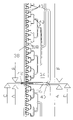
- FIG. 3 a front view of the liquid distributor.
- FIG. 4 a a detail of the rear view of the liquid distributor
- FIG. 4 b a cross section through FIG. 4 a along line D—D;
- FIGS. 5 a , 5 b , and 5 c are cross sectional views taken along lines A—A, B—B and C—C in FIG. 3 ;
- FIGS. 6 and 7 an alternative design of the liquid distributor
- FIG. 8 a detail of FIG. 3 .
- the typical design of the invention shown in FIG. 1 has a multitude of vertical reactor double plates 2 , which are arranged side-by-side with some space in-between.
- Each of the reactor double plates 2 has one upper end 4 , one lower end 6 , one first and one second main surface 8 and 10 respectively, and a void 12 between first and second main surface 8 and 10 .
- the void 12 is shaped to form a heat transfer duct system 14 , in which e.g. water can circulate as a heating or cooling media HKM.
- a mass transfer duct system 16 is formed between the individual reactor double plates 2 .
- the first and second main surfaces 8 and 10 of the reactor double plates 2 are designed as mass and heat transfer surfaces 18 .
- the mass and heat transfer surfaces 18 are moistened continuously from the top by a liquid medium FM or a sorbent. From the bottom, in counter-flow direction, a gaseous medium flows between the reactor double plates, which releases—in case of absorption—a gaseous component into the sorbent FM and absorbs the same gaseous component from the sorbent FM in case of desorption.
- a liquid distributor or ultra low flow liquid distributor 20 is attached, which provides sorbent FM across the entire width of the reactor double plates 2 on all mass and heat transfer surfaces 18 to form a thin film of liquid. Details of the liquid distributor 20 are described in FIGS. 3 , 4 and 5 .
- the mass and heat transfer surfaces 18 have a coating 21 consisting of small solid particles 22 , for example sand grains, as schematically shown in FIG. 2 .
- the mass and heat transfer surfaces 18 thus have a surface like sandpaper.
- gaps and voids 24 are formed between the individual solid particles or sand grains 22 .
- These small gaps and voids 24 by their capillary effect cause the even distribution of sorbent FM in the form of a thin liquid film 26 on the mass and heat transfer surfaces 18 .
- the sand grains 22 are applied individually, side-by-side on the mass and heat transfer surfaces 18 . This single layer application enables the formation of a very thin film of liquid.
- the coating 21 and the sand grains 22 are fixed permanently on the mass and heat transfer surface 18 , using glue.
- the coating can be fixed onto an intermediate carrier, which is not shown, which itself can be fixed onto the mass and heat transfer surfaces 18 .
- FIG. 3 to 5 show a typical design of a liquid distributor 20 , which is used to apply the liquid sorbent FM from the upper end 4 of the reactor double plates 2 onto the mass and heat transfer surfaces 18 .
- the liquid distributor 20 consists of a base body 27 in the form of a rectangular panel with a front side 28 and a rear side 29 .
- the width “b” and thickness “d” of the liquid distributor correspond to the width and thickness of the reactor double plates 2 .
- front and rear liquid outlet openings 30 and 32 are situated at regular intervals side by side, whereby the front and rear openings 30 and 32 are alternating. Therefore the front liquid outlets 30 moisten the front side 28 of the liquid distributor 20 and the first main surface 8 of a reactor double plate 2 , while the rear liquid outlet openings 32 moisten the rear side 29 and the second main surface 10 .
- the liquid outlet openings 30 and 32 receive the liquid or sorbent FM, respectively via a liquid supply system 34 .
- the liquid supply system 34 which is shown on the front side 28 , includes a common main supply 36 and a multitude of sub-mains 38 .
- the liquid main supply 36 is branched by repetitive bifurcations 40 into liquid supply sub-mains 38 , until one liquid supply sub-main 38 is available for each liquid outlet opening 30 and 32 .
- the design as shown in FIG. 3 has 64 liquid outlet openings 30 leading to the first main surface 8 and 64 liquid outlet openings 32 leading to the second main surface 10 .
- the liquid main supply 36 branches at the first bifurcation 40 into two sub-mains 38 , which are split another five times, every time into two sub mains until one individual sub main 38 is available for each of the 128 liquid outlet openings 30 and 32 .
- the liquid main supply 36 is equipped with a connection pipe 42 , which lies above the upper edge of the liquid distributor 20 and serves to feed the liquid sorbent into the system.
- the liquid main supply 36 ends at the lowest point of the liquid supply system 34 and the liquid supply sub-mains 38 are always directed either horizontally or vertically, pointing upwards against gravity. This arrangement of liquid supply sub mains 38 prevents the formation of gas bubbles in the liquid supply system 34 , which could lead to a discontinuous film formation.
- FIGS. 5 a and 5 c show that the liquid supply openings 30 and 32 are tapered, with the wider opening pointing outwards. This shape prevents the formation of droplets when liquid sorbent FM leaves the liquid outlet openings 30 and 32 and ensures the continuous moistening of the mass and heat transfer surfaces 18 .
- both front side 28 and rear side 29 of the liquid distributor 20 are equipped with the same coating 21 as the mass and heat transfer surfaces 18 . This ensures a continuous formation of a liquid film, starting from the liquid outlet openings 30 , 32 and reaching to the lower end 6 of the mass and heat transfer surfaces 18 .
- the liquid distributor 20 is plugged onto the respective reactor double plate 2 with a plug and socket connection 44 .
- the cross section of the plug and socket connection 44 resembles the letter “M”, as displayed in FIGS. 5 a , 5 b and 5 c .
- It is equipped with a center plugging strip 46 , which protrudes out of the bottom and left, right, in the front and the rear a front cover strip 48 and a rear cover strip 50 .
- the front cover strip 48 overlaps the first main surface 8 and the rear cover strip 50 overlaps the second main surface 10 .
- FIGS. 6 and 7 show cross sectional views of alternative designs of the liquid distributor 20 .
- the designs in accordance with FIGS. 6 and 7 are different from the design in accordance with FIG. 5 with regard to the shape of the liquid outlet openings 30 and 32 .
- the front and rear liquid outlet openings 30 and 32 are at the same level and are not staggered sideways, as in the design in accordance with FIG. 5 .
- the liquid supply sub-mains are directly connected with the liquid supply openings 30 and 32 and lead diagonally outwards and upwards to the top.
- these last liquid supply sub-mains 38 lead horizontally outwards.
- the bifurcation 40 is rounded off to prevent turbulence and irregularities in the flow speed.
- FIG. 8 shows a detail of FIG. 3 with rounded bifurcations 40 .
- the liquid supply sub-mains are provided with a wedge-shaped bulge, which complements the rounded form of the bifurcation.
- the minimum cross section of the liquid supply sub-mains 38 is designed to be twice the size of the largest expected dust particle (typically 1 mm 2 ).
- the ultra low flow liquid distributor as described above is particularly suitable for use in a mass and heat transfer reactor for the dehumidification and cooling of air.
- the air is dehumidified by means of a sorbent while at the same time the absorbing liquid, usually a watery salt solution containing one or several salts, is considerably diluted (absorption).
- the air is humidified and the sorbens re-concentrated (Desorption).
- the heating and cooling liquid which circulates in the heat transfer duct system 14 separated from the liquid sorbent FM and the air GM, transfers heat into or out of the sorption process (Desorption or Absorption).
- the cooling water HKM is ducted in counter-flow or cross-counter-flow direction to the airflow.
- the mass and heat transfer surfaces 18 which separate the sorbent FM and the air GM from the cooling and heating agent HKM, at the void 12 between the reactor double plates 2 are in complete contact with the heating and cooling media HKM and the other side, i.e. the mass and heat transfer surfaces 18 are moistened with the liquid sorbent FM.
- the liquid sorbent FM forms an extremely thin, continuous film 26 on the mass and heat transfer surfaces 18 , which flows down the mass and heat transfer surfaces 18 , following gravity.
- the continuous sorbent film 26 is achieved by use of a special coating 21 consisting of small solid particles 22 , which enables an extremely small amount of sorbent to form a continuous moist surface on the mass and heat transfer surfaces 18 and which runs continuously to the bottom.
- the extremely small amount of sorbent is distributed by the liquid distributor 20 across the upper edge of the mass and heat transfer surfaces 18 over the entire width of the reactor double plate 2 , without forming droplets, which could be carried out by the airflow.
- the liquid distributor 20 does not or only minimally protrude into the free cross section for the airflow between the reactor double plates 2 , so that no significant disturbance of the airflow occurs, which would lead to an increased pressure loss.
- the entire the mass and heat transfer reactor can be manufactured in plastic (Polymers) and can be designed very thin.
- the thickness of the individual reactor double plates 2 for example is 3 mm.
- fins (not shown) are inserted at regular intervals, so that the cooling liquid HKM flows through in the form of a meander.
- the mass transfer duct system 16 which is formed between the reactor double plates 2 , air GM flows against gravity while liquid sorbent FM flows with gravity, forming a direct, continuous counter flow.
Landscapes
- Chemical & Material Sciences (AREA)
- Engineering & Computer Science (AREA)
- Chemical Kinetics & Catalysis (AREA)
- Organic Chemistry (AREA)
- Mechanical Engineering (AREA)
- General Engineering & Computer Science (AREA)
- Physics & Mathematics (AREA)
- Thermal Sciences (AREA)
- Combustion & Propulsion (AREA)
- Physical Or Chemical Processes And Apparatus (AREA)
- Gas Separation By Absorption (AREA)
Applications Claiming Priority (4)
| Application Number | Priority Date | Filing Date | Title |
|---|---|---|---|
| DE10141526 | 2001-08-24 | ||
| DE10141526.5 | 2001-08-24 | ||
| DE10141526A DE10141526A1 (de) | 2001-08-24 | 2001-08-24 | Kleinstflüssigkeitsmengenverteiler |
| PCT/EP2002/009458 WO2003019097A1 (de) | 2001-08-24 | 2002-08-23 | Kleinstflüssigkeitsmengenverteiler |
Publications (2)
| Publication Number | Publication Date |
|---|---|
| US20040195708A1 US20040195708A1 (en) | 2004-10-07 |
| US7021608B2 true US7021608B2 (en) | 2006-04-04 |
Family
ID=7696491
Family Applications (1)
| Application Number | Title | Priority Date | Filing Date |
|---|---|---|---|
| US10/486,822 Expired - Fee Related US7021608B2 (en) | 2001-08-24 | 2002-08-23 | Distributor for micro-quantities of liquid |
Country Status (6)
| Country | Link |
|---|---|
| US (1) | US7021608B2 (de) |
| EP (1) | EP1438544B1 (de) |
| JP (1) | JP2005500905A (de) |
| DE (1) | DE10141526A1 (de) |
| ES (1) | ES2254734T3 (de) |
| WO (1) | WO2003019097A1 (de) |
Cited By (7)
| Publication number | Priority date | Publication date | Assignee | Title |
|---|---|---|---|---|
| WO2008113806A1 (en) * | 2007-03-22 | 2008-09-25 | Dsm Fine Chemicals Austria Nfg Gmbh & Co Kg | Reaction plates with alternative, unordered microstuctured surfaces for microreactors for performing gas-liquid reactions |
| US20110192217A1 (en) * | 2010-02-08 | 2011-08-11 | Agilent Technologies, Inc. | Flow Distribution Mixer |
| USRE42882E1 (en) * | 2001-05-17 | 2011-11-01 | Amalgamated Research, Inc. | Fractal device for mixing and reactor applications |
| CN102325589A (zh) * | 2008-12-23 | 2012-01-18 | 康宁股份有限公司 | 微通道反应器 |
| US11209222B1 (en) | 2020-08-20 | 2021-12-28 | Hamilton Sundstrand Corporation | Spiral heat exchanger header |
| US11268770B2 (en) | 2019-09-06 | 2022-03-08 | Hamilton Sunstrand Corporation | Heat exchanger with radially converging manifold |
| US11280550B2 (en) * | 2019-03-08 | 2022-03-22 | Hamilton Sundstrand Corporation | Radially layered helical core geometry for heat exchanger |
Families Citing this family (9)
| Publication number | Priority date | Publication date | Assignee | Title |
|---|---|---|---|---|
| JP4973721B2 (ja) * | 2009-12-07 | 2012-07-11 | 東ソー株式会社 | 微小粒子構造体およびそれを用いた微小粒子の製造方法 |
| DE102012011520A1 (de) * | 2012-06-08 | 2013-12-12 | Fraunhofer-Gesellschaft zur Förderung der angewandten Forschung e.V. | Wärmetauschersystem, Verfahren zu dessenHerstellung sowie Fluidverteilungselement |
| NL2013989B1 (en) * | 2014-10-02 | 2016-09-07 | 2Ndair B V | A method of conditioning air and an air-conditioner module. |
| WO2016053099A1 (en) * | 2014-10-02 | 2016-04-07 | 2Ndair B.V. | Heat and mass exchange module and use thereof |
| EP3381531A1 (de) * | 2017-03-31 | 2018-10-03 | Vrije Universiteit Brussel | Flussverteiler |
| US11274886B2 (en) | 2019-03-08 | 2022-03-15 | Hamilton Sundstrand Corporation | Heat exchanger header with fractal geometry |
| US11359864B2 (en) | 2019-03-08 | 2022-06-14 | Hamilton Sundstrand Corporation | Rectangular helical core geometry for heat exchanger |
| CN111412762A (zh) * | 2020-05-09 | 2020-07-14 | 常州市云凌节能科技有限公司 | 一种新型复合流式闭式冷却塔 |
| CN119016002B (zh) * | 2024-10-30 | 2025-03-11 | 中国科学技术大学先进技术研究院 | 微型反应器 |
Citations (10)
| Publication number | Priority date | Publication date | Assignee | Title |
|---|---|---|---|---|
| US2490080A (en) * | 1944-05-19 | 1949-12-06 | Francis L Melvill | Contacting apparatus |
| FR978800A (fr) | 1948-01-10 | 1951-04-18 | Directie Staatsmijnen Nl | Réfrigérant à ruissellement |
| US5250234A (en) * | 1992-10-08 | 1993-10-05 | Koch Engineering Company, Inc. | Liquid distributor apparatus and method for high viscosity liquids |
| US5354460A (en) | 1993-01-28 | 1994-10-11 | The Amalgamated Sugar Company | Fluid transfer system with uniform fluid distributor |
| DE4312743A1 (de) | 1993-04-20 | 1994-12-22 | Kuemmerling Andreas | Zylinderförmige Kompakt-Leuchtstofflampe |
| US5439620A (en) * | 1994-01-12 | 1995-08-08 | Mitsubishi Corporation | Liquid distributor to be used in substance and/or heat exchanging |
| US6367782B1 (en) * | 2000-09-12 | 2002-04-09 | Research Products Corporation | Water distributor |
| DE10051531A1 (de) | 2000-10-17 | 2002-05-02 | Wicona Bausysteme Gmbh | "Verfahren zur Schalldämmung verschließbarer Fassadenöffnungen und schallgedämpfte Fensterelemente" |
| US6450485B1 (en) * | 1998-10-08 | 2002-09-17 | Ff Seeley Nominees Pty Ltd | Water entry to the water distribution for evaporative coolers |
| US20030111744A1 (en) * | 2000-05-18 | 2003-06-19 | Manteufel Rolf P.C. | Device for guiding the flow of a liquid used for material and/or energy exchange in a wash column |
Family Cites Families (3)
| Publication number | Priority date | Publication date | Assignee | Title |
|---|---|---|---|---|
| DE3640886C1 (de) | 1986-11-29 | 1988-06-09 | Raschig Ag | Fluessigkeitsverteiler fuer Stoff- und Waermeaustauschkolonnen |
| DE4321743A1 (de) | 1992-06-30 | 1994-03-17 | Fraunhofer Ges Forschung | Wärme- und Stoffaustauschreaktor |
| JP2003512144A (ja) * | 1999-10-18 | 2003-04-02 | マントイフェル、ロルフ・ピー・シー | 洗浄塔内で物質及び/又はエネルギ交換する方法及び装置 |
-
2001
- 2001-08-24 DE DE10141526A patent/DE10141526A1/de not_active Ceased
-
2002
- 2002-08-23 JP JP2003523917A patent/JP2005500905A/ja not_active Withdrawn
- 2002-08-23 ES ES02767424T patent/ES2254734T3/es not_active Expired - Lifetime
- 2002-08-23 EP EP02767424A patent/EP1438544B1/de not_active Expired - Lifetime
- 2002-08-23 US US10/486,822 patent/US7021608B2/en not_active Expired - Fee Related
- 2002-08-23 WO PCT/EP2002/009458 patent/WO2003019097A1/de not_active Ceased
Patent Citations (10)
| Publication number | Priority date | Publication date | Assignee | Title |
|---|---|---|---|---|
| US2490080A (en) * | 1944-05-19 | 1949-12-06 | Francis L Melvill | Contacting apparatus |
| FR978800A (fr) | 1948-01-10 | 1951-04-18 | Directie Staatsmijnen Nl | Réfrigérant à ruissellement |
| US5250234A (en) * | 1992-10-08 | 1993-10-05 | Koch Engineering Company, Inc. | Liquid distributor apparatus and method for high viscosity liquids |
| US5354460A (en) | 1993-01-28 | 1994-10-11 | The Amalgamated Sugar Company | Fluid transfer system with uniform fluid distributor |
| DE4312743A1 (de) | 1993-04-20 | 1994-12-22 | Kuemmerling Andreas | Zylinderförmige Kompakt-Leuchtstofflampe |
| US5439620A (en) * | 1994-01-12 | 1995-08-08 | Mitsubishi Corporation | Liquid distributor to be used in substance and/or heat exchanging |
| US6450485B1 (en) * | 1998-10-08 | 2002-09-17 | Ff Seeley Nominees Pty Ltd | Water entry to the water distribution for evaporative coolers |
| US20030111744A1 (en) * | 2000-05-18 | 2003-06-19 | Manteufel Rolf P.C. | Device for guiding the flow of a liquid used for material and/or energy exchange in a wash column |
| US6367782B1 (en) * | 2000-09-12 | 2002-04-09 | Research Products Corporation | Water distributor |
| DE10051531A1 (de) | 2000-10-17 | 2002-05-02 | Wicona Bausysteme Gmbh | "Verfahren zur Schalldämmung verschließbarer Fassadenöffnungen und schallgedämpfte Fensterelemente" |
Cited By (10)
| Publication number | Priority date | Publication date | Assignee | Title |
|---|---|---|---|---|
| USRE42882E1 (en) * | 2001-05-17 | 2011-11-01 | Amalgamated Research, Inc. | Fractal device for mixing and reactor applications |
| WO2008113806A1 (en) * | 2007-03-22 | 2008-09-25 | Dsm Fine Chemicals Austria Nfg Gmbh & Co Kg | Reaction plates with alternative, unordered microstuctured surfaces for microreactors for performing gas-liquid reactions |
| CN102325589A (zh) * | 2008-12-23 | 2012-01-18 | 康宁股份有限公司 | 微通道反应器 |
| CN102325589B (zh) * | 2008-12-23 | 2014-07-09 | 康宁股份有限公司 | 微通道反应器 |
| US20110192217A1 (en) * | 2010-02-08 | 2011-08-11 | Agilent Technologies, Inc. | Flow Distribution Mixer |
| US8511889B2 (en) * | 2010-02-08 | 2013-08-20 | Agilent Technologies, Inc. | Flow distribution mixer |
| US11280550B2 (en) * | 2019-03-08 | 2022-03-22 | Hamilton Sundstrand Corporation | Radially layered helical core geometry for heat exchanger |
| US11268770B2 (en) | 2019-09-06 | 2022-03-08 | Hamilton Sunstrand Corporation | Heat exchanger with radially converging manifold |
| US12130090B2 (en) | 2019-09-06 | 2024-10-29 | Hamilton Sundstrand Corporation | Heat exchanger with radially converging manifold |
| US11209222B1 (en) | 2020-08-20 | 2021-12-28 | Hamilton Sundstrand Corporation | Spiral heat exchanger header |
Also Published As
| Publication number | Publication date |
|---|---|
| WO2003019097A1 (de) | 2003-03-06 |
| EP1438544B1 (de) | 2005-12-28 |
| EP1438544A1 (de) | 2004-07-21 |
| DE10141526A1 (de) | 2003-04-17 |
| JP2005500905A (ja) | 2005-01-13 |
| US20040195708A1 (en) | 2004-10-07 |
| ES2254734T3 (es) | 2006-06-16 |
Similar Documents
| Publication | Publication Date | Title |
|---|---|---|
| US7021608B2 (en) | Distributor for micro-quantities of liquid | |
| US6848265B2 (en) | Air conditioning system | |
| US4139584A (en) | Contact body for liquid and gas | |
| EP1836046B1 (de) | Verfahren und materialien zur verbesserung von verdunstungswärmetauschern | |
| CN1997861A (zh) | 热质交换器 | |
| US6523604B1 (en) | Indirect evaporative cooling apparatus | |
| US20110041531A1 (en) | Evaporative cooler | |
| US9993743B2 (en) | Distributor tray for gas/liquid contact column with secondary distribution system | |
| US4782857A (en) | Method and apparatus for uniformly distributing solids-containing liquid | |
| KR101603367B1 (ko) | 병류 접촉 장치 내 액체 분배 개선 | |
| RU2073174C1 (ru) | Установка для косвенно-испарительного охлаждения воздуха | |
| CN108981416B (zh) | 洗涤塔尾气降温装置及气体净化系统 | |
| JP7243057B2 (ja) | 気液接触装置 | |
| KR20230072044A (ko) | 트레이 | |
| AU2010201392B2 (en) | Method and Means for Operating Evaporative Coolers | |
| RU2203726C1 (ru) | Пленочный распределитель жидкости | |
| US5980617A (en) | Gas processing contactor tower | |
| KR101692939B1 (ko) | 유체분배기 및 이를 구비한 열교환기 | |
| HK1090114A (en) | Evaporative cooler | |
| WO2016085895A1 (en) | System and method for the handling of a fluid in a heat and mass exchanger | |
| CS217814B1 (cs) | Rozdělovač kapaliny | |
| UA80946C2 (en) | Cap with semi-transparent aerodynamic screens above fluid films for contact heat-mass-transfer apparatus | |
| SE434995B (sv) | Anordning vid evaporativa kontaktkroppar anordning vid evaporativa kontaktkroppar | |
| CS255963B1 (cs) | Zařízení k rozdělování kapaliny po vodorovném průřezu kolonového aparátu | |
| MXPA01003587A (en) | Improvements in water spreading in evaporative coolers |
Legal Events
| Date | Code | Title | Description |
|---|---|---|---|
| FEPP | Fee payment procedure |
Free format text: PAYOR NUMBER ASSIGNED (ORIGINAL EVENT CODE: ASPN); ENTITY STATUS OF PATENT OWNER: SMALL ENTITY |
|
| FPAY | Fee payment |
Year of fee payment: 4 |
|
| REMI | Maintenance fee reminder mailed | ||
| FPAY | Fee payment |
Year of fee payment: 8 |
|
| SULP | Surcharge for late payment |
Year of fee payment: 7 |
|
| FEPP | Fee payment procedure |
Free format text: MAINTENANCE FEE REMINDER MAILED (ORIGINAL EVENT CODE: REM.) |
|
| LAPS | Lapse for failure to pay maintenance fees |
Free format text: PATENT EXPIRED FOR FAILURE TO PAY MAINTENANCE FEES (ORIGINAL EVENT CODE: EXP.) |
|
| STCH | Information on status: patent discontinuation |
Free format text: PATENT EXPIRED DUE TO NONPAYMENT OF MAINTENANCE FEES UNDER 37 CFR 1.362 |
|
| FP | Lapsed due to failure to pay maintenance fee |
Effective date: 20180404 |