US6969543B1 - Intermediate transfer blanket and method of producing the same - Google Patents
Intermediate transfer blanket and method of producing the same Download PDFInfo
- Publication number
- US6969543B1 US6969543B1 US09/011,634 US1163498A US6969543B1 US 6969543 B1 US6969543 B1 US 6969543B1 US 1163498 A US1163498 A US 1163498A US 6969543 B1 US6969543 B1 US 6969543B1
- Authority
- US
- United States
- Prior art keywords
- layer
- image transfer
- transfer member
- member according
- layers
- Prior art date
- Legal status (The legal status is an assumption and is not a legal conclusion. Google has not performed a legal analysis and makes no representation as to the accuracy of the status listed.)
- Expired - Fee Related
Links
- 238000012546 transfer Methods 0.000 title claims abstract description 229
- 238000000034 method Methods 0.000 title abstract description 28
- 239000000463 material Substances 0.000 claims description 64
- 239000006229 carbon black Substances 0.000 claims description 14
- 239000007788 liquid Substances 0.000 claims description 12
- 239000003351 stiffener Substances 0.000 claims 3
- 239000000758 substrate Substances 0.000 abstract description 40
- 239000010410 layer Substances 0.000 description 269
- 239000000203 mixture Substances 0.000 description 19
- 235000019589 hardness Nutrition 0.000 description 18
- 238000003384 imaging method Methods 0.000 description 16
- 230000008569 process Effects 0.000 description 16
- 238000000576 coating method Methods 0.000 description 14
- 239000011248 coating agent Substances 0.000 description 13
- 239000000853 adhesive Substances 0.000 description 12
- 230000001070 adhesive effect Effects 0.000 description 12
- 239000000945 filler Substances 0.000 description 12
- 238000003475 lamination Methods 0.000 description 12
- 230000004888 barrier function Effects 0.000 description 11
- ZWEHNKRNPOVVGH-UHFFFAOYSA-N 2-Butanone Chemical compound CCC(C)=O ZWEHNKRNPOVVGH-UHFFFAOYSA-N 0.000 description 9
- YXFVVABEGXRONW-UHFFFAOYSA-N Toluene Chemical compound CC1=CC=CC=C1 YXFVVABEGXRONW-UHFFFAOYSA-N 0.000 description 9
- VLKZOEOYAKHREP-UHFFFAOYSA-N n-Hexane Chemical compound CCCCCC VLKZOEOYAKHREP-UHFFFAOYSA-N 0.000 description 9
- 229920001296 polysiloxane Polymers 0.000 description 9
- 239000007787 solid Substances 0.000 description 9
- 239000004971 Cross linker Substances 0.000 description 7
- 229920002545 silicone oil Polymers 0.000 description 7
- OKTJSMMVPCPJKN-UHFFFAOYSA-N Carbon Chemical compound [C] OKTJSMMVPCPJKN-UHFFFAOYSA-N 0.000 description 6
- 230000015572 biosynthetic process Effects 0.000 description 6
- 239000003054 catalyst Substances 0.000 description 6
- 150000001875 compounds Chemical class 0.000 description 6
- 229910052751 metal Inorganic materials 0.000 description 6
- 239000002184 metal Substances 0.000 description 6
- CNPVJWYWYZMPDS-UHFFFAOYSA-N 2-methyldecane Chemical compound CCCCCCCCC(C)C CNPVJWYWYZMPDS-UHFFFAOYSA-N 0.000 description 5
- 239000004744 fabric Substances 0.000 description 5
- 230000007246 mechanism Effects 0.000 description 5
- 239000004814 polyurethane Substances 0.000 description 5
- 239000004925 Acrylic resin Substances 0.000 description 4
- 229920000178 Acrylic resin Polymers 0.000 description 4
- VTYYLEPIZMXCLO-UHFFFAOYSA-L Calcium carbonate Chemical compound [Ca+2].[O-]C([O-])=O VTYYLEPIZMXCLO-UHFFFAOYSA-L 0.000 description 4
- 229920000800 acrylic rubber Polymers 0.000 description 4
- 238000009833 condensation Methods 0.000 description 4
- 230000005494 condensation Effects 0.000 description 4
- 239000004020 conductor Substances 0.000 description 4
- 238000010030 laminating Methods 0.000 description 4
- 238000007645 offset printing Methods 0.000 description 4
- 108091008695 photoreceptors Proteins 0.000 description 4
- 229920000642 polymer Polymers 0.000 description 4
- 229920002635 polyurethane Polymers 0.000 description 4
- 238000007639 printing Methods 0.000 description 4
- RYYKJJJTJZKILX-UHFFFAOYSA-M sodium octadecanoate Chemical compound [Na+].CCCCCCCCCCCCCCCCCC([O-])=O RYYKJJJTJZKILX-UHFFFAOYSA-M 0.000 description 4
- 229920002799 BoPET Polymers 0.000 description 3
- 239000005041 Mylar™ Substances 0.000 description 3
- 229920000459 Nitrile rubber Polymers 0.000 description 3
- 239000004372 Polyvinyl alcohol Substances 0.000 description 3
- NIXOWILDQLNWCW-UHFFFAOYSA-N acrylic acid group Chemical group C(C=C)(=O)O NIXOWILDQLNWCW-UHFFFAOYSA-N 0.000 description 3
- 239000000654 additive Substances 0.000 description 3
- 239000012790 adhesive layer Substances 0.000 description 3
- 229920005645 diorganopolysiloxane polymer Polymers 0.000 description 3
- 229920001971 elastomer Polymers 0.000 description 3
- 239000000806 elastomer Substances 0.000 description 3
- 238000010438 heat treatment Methods 0.000 description 3
- 230000006872 improvement Effects 0.000 description 3
- 239000004922 lacquer Substances 0.000 description 3
- 238000004519 manufacturing process Methods 0.000 description 3
- VNWKTOKETHGBQD-UHFFFAOYSA-N methane Chemical compound C VNWKTOKETHGBQD-UHFFFAOYSA-N 0.000 description 3
- 229920002451 polyvinyl alcohol Polymers 0.000 description 3
- 239000012858 resilient material Substances 0.000 description 3
- LFQSCWFLJHTTHZ-UHFFFAOYSA-N Ethanol Chemical compound CCO LFQSCWFLJHTTHZ-UHFFFAOYSA-N 0.000 description 2
- 101000801643 Homo sapiens Retinal-specific phospholipid-transporting ATPase ABCA4 Proteins 0.000 description 2
- 102100033617 Retinal-specific phospholipid-transporting ATPase ABCA4 Human genes 0.000 description 2
- BOTDANWDWHJENH-UHFFFAOYSA-N Tetraethyl orthosilicate Chemical compound CCO[Si](OCC)(OCC)OCC BOTDANWDWHJENH-UHFFFAOYSA-N 0.000 description 2
- 239000003963 antioxidant agent Substances 0.000 description 2
- 235000006708 antioxidants Nutrition 0.000 description 2
- 229910000019 calcium carbonate Inorganic materials 0.000 description 2
- 238000010276 construction Methods 0.000 description 2
- 230000006866 deterioration Effects 0.000 description 2
- 238000009472 formulation Methods 0.000 description 2
- 239000007789 gas Substances 0.000 description 2
- 238000002386 leaching Methods 0.000 description 2
- 229920003223 poly(pyromellitimide-1,4-diphenyl ether) Polymers 0.000 description 2
- 229920000058 polyacrylate Polymers 0.000 description 2
- 238000006116 polymerization reaction Methods 0.000 description 2
- 229920002631 room-temperature vulcanizate silicone Polymers 0.000 description 2
- 239000002904 solvent Substances 0.000 description 2
- 238000003756 stirring Methods 0.000 description 2
- KSBAEPSJVUENNK-UHFFFAOYSA-L tin(ii) 2-ethylhexanoate Chemical compound [Sn+2].CCCCC(CC)C([O-])=O.CCCCC(CC)C([O-])=O KSBAEPSJVUENNK-UHFFFAOYSA-L 0.000 description 2
- BPSIOYPQMFLKFR-UHFFFAOYSA-N trimethoxy-[3-(oxiran-2-ylmethoxy)propyl]silane Chemical compound CO[Si](OC)(OC)CCCOCC1CO1 BPSIOYPQMFLKFR-UHFFFAOYSA-N 0.000 description 2
- XLYOFNOQVPJJNP-UHFFFAOYSA-N water Substances O XLYOFNOQVPJJNP-UHFFFAOYSA-N 0.000 description 2
- VYZAMTAEIAYCRO-UHFFFAOYSA-N Chromium Chemical compound [Cr] VYZAMTAEIAYCRO-UHFFFAOYSA-N 0.000 description 1
- 229920000784 Nomex Polymers 0.000 description 1
- 229910000831 Steel Inorganic materials 0.000 description 1
- 230000009471 action Effects 0.000 description 1
- 230000000996 additive effect Effects 0.000 description 1
- 229910052782 aluminium Inorganic materials 0.000 description 1
- XAGFODPZIPBFFR-UHFFFAOYSA-N aluminium Chemical compound [Al] XAGFODPZIPBFFR-UHFFFAOYSA-N 0.000 description 1
- 238000007664 blowing Methods 0.000 description 1
- 238000005119 centrifugation Methods 0.000 description 1
- 238000013329 compounding Methods 0.000 description 1
- 230000002596 correlated effect Effects 0.000 description 1
- 238000005520 cutting process Methods 0.000 description 1
- 230000009849 deactivation Effects 0.000 description 1
- 230000001419 dependent effect Effects 0.000 description 1
- 238000013461 design Methods 0.000 description 1
- 238000001035 drying Methods 0.000 description 1
- 230000000694 effects Effects 0.000 description 1
- 238000002474 experimental method Methods 0.000 description 1
- 239000000835 fiber Substances 0.000 description 1
- 239000010408 film Substances 0.000 description 1
- 238000001914 filtration Methods 0.000 description 1
- 239000012467 final product Substances 0.000 description 1
- -1 for example Chemical compound 0.000 description 1
- 239000003292 glue Substances 0.000 description 1
- 238000000227 grinding Methods 0.000 description 1
- 229910052736 halogen Inorganic materials 0.000 description 1
- 150000002367 halogens Chemical class 0.000 description 1
- 238000003780 insertion Methods 0.000 description 1
- 230000037431 insertion Effects 0.000 description 1
- JEIPFZHSYJVQDO-UHFFFAOYSA-N iron(III) oxide Inorganic materials O=[Fe]O[Fe]=O JEIPFZHSYJVQDO-UHFFFAOYSA-N 0.000 description 1
- 238000002955 isolation Methods 0.000 description 1
- 239000003273 ketjen black Substances 0.000 description 1
- 238000002156 mixing Methods 0.000 description 1
- 239000004763 nomex Substances 0.000 description 1
- TWNQGVIAIRXVLR-UHFFFAOYSA-N oxo(oxoalumanyloxy)alumane Chemical compound O=[Al]O[Al]=O TWNQGVIAIRXVLR-UHFFFAOYSA-N 0.000 description 1
- 239000002245 particle Substances 0.000 description 1
- 230000035515 penetration Effects 0.000 description 1
- 229920000728 polyester Polymers 0.000 description 1
- 229920001225 polyester resin Polymers 0.000 description 1
- 239000004645 polyester resin Substances 0.000 description 1
- 229920003225 polyurethane elastomer Polymers 0.000 description 1
- 239000000843 powder Substances 0.000 description 1
- 230000002028 premature Effects 0.000 description 1
- 230000007420 reactivation Effects 0.000 description 1
- 238000010992 reflux Methods 0.000 description 1
- 239000011347 resin Substances 0.000 description 1
- 229920005989 resin Polymers 0.000 description 1
- 230000004044 response Effects 0.000 description 1
- 239000011369 resultant mixture Substances 0.000 description 1
- 229920006395 saturated elastomer Polymers 0.000 description 1
- 239000013464 silicone adhesive Substances 0.000 description 1
- 229910001220 stainless steel Inorganic materials 0.000 description 1
- 239000010935 stainless steel Substances 0.000 description 1
- 239000010959 steel Substances 0.000 description 1
- 239000000126 substance Substances 0.000 description 1
- 239000010409 thin film Substances 0.000 description 1
Images


Classifications
-
- G—PHYSICS
- G03—PHOTOGRAPHY; CINEMATOGRAPHY; ANALOGOUS TECHNIQUES USING WAVES OTHER THAN OPTICAL WAVES; ELECTROGRAPHY; HOLOGRAPHY
- G03G—ELECTROGRAPHY; ELECTROPHOTOGRAPHY; MAGNETOGRAPHY
- G03G15/00—Apparatus for electrographic processes using a charge pattern
- G03G15/14—Apparatus for electrographic processes using a charge pattern for transferring a pattern to a second base
- G03G15/16—Apparatus for electrographic processes using a charge pattern for transferring a pattern to a second base of a toner pattern, e.g. a powder pattern, e.g. magnetic transfer
- G03G15/1605—Apparatus for electrographic processes using a charge pattern for transferring a pattern to a second base of a toner pattern, e.g. a powder pattern, e.g. magnetic transfer using at least one intermediate support
- G03G15/161—Apparatus for electrographic processes using a charge pattern for transferring a pattern to a second base of a toner pattern, e.g. a powder pattern, e.g. magnetic transfer using at least one intermediate support with means for handling the intermediate support, e.g. heating, cleaning, coating with a transfer agent
-
- G—PHYSICS
- G03—PHOTOGRAPHY; CINEMATOGRAPHY; ANALOGOUS TECHNIQUES USING WAVES OTHER THAN OPTICAL WAVES; ELECTROGRAPHY; HOLOGRAPHY
- G03G—ELECTROGRAPHY; ELECTROPHOTOGRAPHY; MAGNETOGRAPHY
- G03G15/00—Apparatus for electrographic processes using a charge pattern
- G03G15/14—Apparatus for electrographic processes using a charge pattern for transferring a pattern to a second base
- G03G15/16—Apparatus for electrographic processes using a charge pattern for transferring a pattern to a second base of a toner pattern, e.g. a powder pattern, e.g. magnetic transfer
- G03G15/1605—Apparatus for electrographic processes using a charge pattern for transferring a pattern to a second base of a toner pattern, e.g. a powder pattern, e.g. magnetic transfer using at least one intermediate support
- G03G15/162—Apparatus for electrographic processes using a charge pattern for transferring a pattern to a second base of a toner pattern, e.g. a powder pattern, e.g. magnetic transfer using at least one intermediate support details of the the intermediate support, e.g. chemical composition
-
- Y—GENERAL TAGGING OF NEW TECHNOLOGICAL DEVELOPMENTS; GENERAL TAGGING OF CROSS-SECTIONAL TECHNOLOGIES SPANNING OVER SEVERAL SECTIONS OF THE IPC; TECHNICAL SUBJECTS COVERED BY FORMER USPC CROSS-REFERENCE ART COLLECTIONS [XRACs] AND DIGESTS
- Y10—TECHNICAL SUBJECTS COVERED BY FORMER USPC
- Y10S—TECHNICAL SUBJECTS COVERED BY FORMER USPC CROSS-REFERENCE ART COLLECTIONS [XRACs] AND DIGESTS
- Y10S428/00—Stock material or miscellaneous articles
- Y10S428/909—Resilient layer, e.g. printer's blanket
-
- Y—GENERAL TAGGING OF NEW TECHNOLOGICAL DEVELOPMENTS; GENERAL TAGGING OF CROSS-SECTIONAL TECHNOLOGIES SPANNING OVER SEVERAL SECTIONS OF THE IPC; TECHNICAL SUBJECTS COVERED BY FORMER USPC CROSS-REFERENCE ART COLLECTIONS [XRACs] AND DIGESTS
- Y10—TECHNICAL SUBJECTS COVERED BY FORMER USPC
- Y10T—TECHNICAL SUBJECTS COVERED BY FORMER US CLASSIFICATION
- Y10T428/00—Stock material or miscellaneous articles
- Y10T428/24—Structurally defined web or sheet [e.g., overall dimension, etc.]
- Y10T428/24942—Structurally defined web or sheet [e.g., overall dimension, etc.] including components having same physical characteristic in differing degree
- Y10T428/24992—Density or compression of components
Definitions
- the present invention relates to improved intermediate transfer blankets, especially suited for transfer of liquid toner images, and methods of producing such blankets.
- intermediate transfer members and members including transfer blankets, for offset ink printing, is also well known.
- Such blankets have characteristics which are suitable for ink transfer but they are generally not usable, per se, for liquid toner imaging.
- Multi-layered intermediate transfer blankets for toner imaging are known in the art.
- such blankets include a thin, multi-layered, image transfer portion and a base (or body) portion which supports the image transfer portion and provides the blanket with resilience during contact with an imaging surface and/or a final substrate. While the process for producing the image transfer portion is a relatively clean process, the base portion is generally not compatible with such clean processes.
- U.S. Pat. No. 4,074,001 describes a fixing roller for electrophotography which has a 3 mm coating of a mixture of diorganopolysiloxanes terminated at both chain ends with diorganohydroxysilyl groups bonded to terminal silicone atoms (a condensation type silicone), diorganopolysiloxanes terminated at both chain ends with trialkysilyl groups (a substantially unreactive silicone oil), a minor part of an alkoxysilane catalyst and various amounts of fillers.
- This material vulcanizes, in the 3 mm thickness, at room temperature.
- a method of producing a multi-layered image transfer blanket including a body portion and an image transfer portion, the image transfer portion having an image transfer surface and a back surface comprising:
- the image transfer portion is formed on the carrier substrate such that the back surface of the image transfer portion faces the carrier substrate.
- the method comprises curing at least one of the layers in said multi-layered blanket after transferring the image transfer portion.
- the image transfer blanket comprises a polymer layer, preferably a conducting layer, interfacing the back surface of the image transfer portion and curing at least one of the layers comprises curing the polymer layer after laminating the image transfer portion onto the body portion.
- the polymer layer is part of the body portion. Additionally or alternatively, the polymer layer is part of the image transfer portion.
- the image transfer portion comprises a release layer at the image transfer surface and a conforming layer and wherein curing at least one layer comprises curing the release layer and the conforming layer before laminating the image transfer portion to the body portion.
- the release layer and the conforming layer are cured after laminating the image transfer portion to the body portion.
- forming the image transfer portion comprises coating the carrier substrate with a conforming layer.
- forming the image transfer portion comprises coating the carrier substrate with a barrier layer.
- forming the image transfer portion comprises coating the carrier substrate with a conductive layer.
- the conforming layer comprises a plurality of layers of different hardnesses.
- forming the image transfer portion comprises overcoating the conforming layer with a release layer, preferably comprising a layer of condensation type silicone.
- an image transfer member suitable for the transfer of toner images and having a non-tacky outer release coating of a condensation type silicone.
- the release layer has a thickness of less than 1 mm, more preferably less than 500 micrometers, even more preferably less than 100 micrometers and most preferably between 3 and 15 micrometers thick.
- the release layer preferably has less than 4% filler, more preferably less than 1% filler, even more preferably less than 0.1% filler.
- the outer release layer contains less than 10% silicone oil, more preferably less than 5% silicone oil, more preferably less than 1% silicone oil, most preferably little or no silicone oil.
- the outer release layer contains added crosslinker.
- the outer release layer contains added catalyst.
- the outer release layer contains added conductive material.
- adhesion of the outer release coating to the image transfer member is enhanced utilizing primer.
- apparatus for producing a multi-layered image transfer blanket including a body portion and an image transfer portion, the image transfer portion having an image transfer surface and a back surface, comprising:
- the apparatus further comprises a curing device which cures at least one of the layers in said multi-layered blanket.
- an image transfer blanket comprising:
- the sub-layers comprise at least two sub-layers, a relatively harder one of said sub-layers being situated between is between the release surface and a relatively softer one of said sub-layers.
- the relatively softer sub-layer has a Shore A hardness of less than 42, less than 35, or less than 25.
- the relatively harder sub-layer has a Shore A hardness of greater than 42, or greater than 50.
- the ratio of the thickness of the relatively harder sub-layer to the thickness of the relatively softer sub-layer is about 1:4.
- an image transfer blanket comprising:
- an intermediate transfer member which receives a toner image from an imaging surface and from which it is subsequently transferred, comprising:
- the supporting base layer comprises a layer of Kapton.
- an intermediate transfer member which receives a toner image from an imaging surface and from which it is subsequently transferred, comprising:
- a predetermined length of used-up sheet is taken-up by the take-up member and replaced with approximately the same length of unused sheet which is supplied the supply member.
- a carrier substrate having formed thereon a multi-layered image transfer arrangement, the image transfer arrangement comprising a back surface and an image transfer surface, wherein the back surface of the image transfer arrangement faces the carrier substrate and is removably attached thereto.
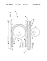
- FIG. 1 is a simplified cross-sectional illustration of an image transfer member, including a multi-layered image transfer blanket mounted on a drum, in accordance with a preferred embodiment of the present invention
- FIGS. 2A and 2B are respective top and side views of the image transfer blanket of FIG. 1 , in accordance with a preferred embodiment of the present invention
- FIG. 2C shows details of the multi-layered construction of the image transfer blanket of FIGS. 2A and 2B , in accordance with one, preferred, embodiment of the present invention
- FIG. 3 is a schematic illustration of apparatus for producing a multi-layered image transfer blanket, constructed and operative in accordance with a preferred embodiment of the present invention
- FIG. 4 is a simplified, schematic illustration of an image transfer blanket having an image transfer portion, constructed in accordance with another, preferred, embodiment of the present invention.
- FIG. 5 is a simplified cross-sectional illustration of an image transfer member, including the image transfer blanket of FIG. 4 mounted on a drum and apparatus for renewing the image transfer portion of the image transfer blanket, constructed and operative in accordance with a preferred embodiment of the invention.
- FIG. 1 is a simplified cross-sectional illustration of an image transfer member 30 , including a multi-layered image transfer blanket 100 mounted on a drum 102 , in accordance with a preferred embodiment of the present invention.
- Image transfer member 30 may, for some embodiments of the invention, be any suitable intermediate transfer member having a multilayered transfer portion such as those described below or in U.S. Pat. No. 5,089,856 or 5,047,808 or in PCT Application PCT/NL 95/00188, filed Jun. 6, 1995, the disclosures of which are incorporated herein by reference and by other structures known in the art.
- member 30 is maintained at a suitable voltage and temperature for electrostatic transfer of a toner image thereto from an image bearing surface, such as a photoreceptor surface.
- the image is preferably transferred from intermediate transfer member 30 onto a final substrate (not shown), such as paper, preferably by heat and pressure.
- a final substrate such as paper
- an image temperature of about 95° C. at the inception of fusing is preferred.
- a plurality of single color images are preferably sequentially transferred, in mutual alignment, to the surface of an image transfer portion 104 of image transfer blanket 100 , by sequential imaging cycles.
- the complete multi-color image is transferred from transfer member 30 to the final substrate.
- each single color image may be separately transferred to the substrate via the intermediate transfer member, as known in the art.
- image transfer portion 104 comprises a release layer 109 which is outermost on the blanket when it is mounted on drum 102 .
- Underlying layer 109 is a conforming layer 111 preferably of a soft elastomer, preferably of polyurethane or acrylic and preferably having a Shore A hardness of less than about 65, more preferably, less than about 55, but preferably more than about 35.
- a suitable hardness value is between about 42 and about 45.
- layer 11 may have sub-layers of varying hardness, as described below.
- a thin barrier layer for solvents and/or gases 114 lies between layer 111 and an underlying conductive layer 115 for some embodiments of the invention. In general, the order of layers 114 and 115 may be reversed.
- Conductive layer 115 overlays a blanket body 116 comprising a top layer 118 , a compressible layer 120 and a fabric layer 122 .
- top layer 118 is conductive and conductive layer 115 may be omitted.
- layer 126 Underlying the fabric layer there may be an adhesive layer 126 which is in contact with drum 102 .
- layer 126 is a very soft, smooth, layer.
- Drum 102 is preferably heated by an internal halogen lamp heater or other heater to aid transfer of the image to the release layer 109 and therefrom to the final substrate, as is well known in the art.
- Other heating methods, or no heating at all, may also be used in the practice of the invention. The degree of heating will depend on the characteristics of the toner and/or ink used in conjunction with the invention.
- mounting fitting 106 comprises an elongate electrically conducting bar 108 , for example of a metal such as aluminum, formed with a series of L-shaped mounting legs 110 (in the form of finger-like extensions) which are also conducting, preferably of the same material as bar 108 , and preferably formed integrally therewith.
- bar 108 is formed, in one preferred embodiment, with a slot into which the end of layered part of blanket 100 is inserted.
- the end of the layered part which is inserted into the mounting bar does not include release layer 109 , conforming layer 111 and barrier layer 114 , whereby conducting layer 115 is exposed and is therefore in electrical contact with bar 108 .
- the slot can be formed with sharp internal projections which pierce the outer layers of the blanket and contact conducting layer 115 or conducting top layer 118 .
- each of the layers beneath conducting layer 115 may be partially conducting (for example, by the addition of conductive carbon black or metal fibers) and the adhesive (or very soft and smooth) layer 126 may be conductive, such that current flows, additionally or alternatively, directly from the drum surface to the conducting layer.
- layer 115 may generally be omitted.
- the conforming layer and/or the release layer are made somewhat conductive (preferably between 10 6 and 10 12 ohm-cm, more preferably, between 10 9 and 10 11 ohm-cm) by the addition of carbon black or between 1% and 10% of anti-static compounds such as CC-42 (Witco).
- the structure and method of attachment of the blanket to drum 30 is not relevant, per se, to the invention.
- fitting 106 is formed of a single sheet of metal, wherein the legs are partially cut from the metal which is bent into a U-shape to form the slot into which the layered portion is inserted. After insertion, the outer walls of the slot are forced against the layered portion to secure the layered portion in the slot and, optionally, to pierce the outer surface of the blanket and contact the conductive layer. The partially cut out portion is bent to form the mounting legs.
- drum 102 is maintained at a potential suitable for transferring images to the intermediate transfer member, for example at a negative voltage of 500 volts, which voltage is applied, via mounting fitting 106 to conductive layer 115 or 118 .
- a potential suitable for transferring images to the intermediate transfer member for example at a negative voltage of 500 volts, which voltage is applied, via mounting fitting 106 to conductive layer 115 or 118 .
- the source of transfer voltage is very near the outer surface of transfer portion 104 which allows for a lower transfer potential on the drum.
- the multi-layered blanket 100 of the present invention is generally similar to that described in PCT/NL 95/00188, except for additional preferred embodiments as described herein.
- the multi-layered blanket of the present invention is produced by a new process, as described below.
- blanket body 116 includes components which may contaminate at least some of the layers in the image transfer portion during production of the blanket. For example, small particles from blanket body 116 , which is generally formed of relatively unclean materials, may break off the body portion and contaminate the relatively clean layers of transfer portion 104 . This may result in low transfer efficiency and poor imaging quality. Therefore, in a preferred embodiment of the present invention, blanket body 116 and image transfer portion 104 are formed separately. The separately formed image transfer portion is consequently laminated onto the blanket body, as described in detail below with reference to FIG. 3 .
- Conducting layer 115 may be coated directly on blanket body 116 or laminated thereon together with the other layers of image transfer portion 104 , as described below. Alternatively, layer 118 is conducting and layer 115 is omitted. Curing of the different layers in the multi-layered blanket may be performed before, after or during lamination of the two portions of the blanket.
- FIG. 3 schematically illustrates apparatus 180 for forming multi-layered image transfer blanket 100 , constructed and operative in accordance with a preferred embodiment of the invention.
- blanket 116 is generally similar to that described in PCT/NL 959/0018.
- One suitable body is MCC-1129-02 manufactured and sold by Reeves SpA, Lodi Vecchio (Milano), Italy.
- Other preferred blanket types are described in U.S. Pat. Nos. 5,047,808; 4,984,025; 5,335,054 and PCT publications WO 91/03007; WO 91/14393; WO 90/14619; and WO 90/04216, which are incorporated herein by reference, and in PCT/NL 95/00188.
- Body portion 116 includes fabric layer 122 , preferably formed of woven NOMEX material having a thickness of about 200 micrometers, compressible layer 120 , preferably comprising about 400 micrometers of saturated nitrile rubber loaded with carbon black to increase its thermal conductivity.
- Layer 120 preferably contains small voids (about 40–60% by volume) and top layer 118 is preferably formed of the same material as the compressible layer, but without voids.
- Blanket body 116 can be produced using production methods as are generally used for the production of offset printing blankets for ink offset printing.
- Blanket body 116 is preferably sized to a relatively exact thickness by abrading portions of the surface of top layer 118 .
- a preferred thickness for the finished body 116 is about 700 micrometers, although other thicknesses are useful, depending on the geometry of the printing system in which it is used and the exact materials used in the blanket body.
- the fabric side of blanket body 116 may be coated with a 30 micrometer thick coating of silicone based adhesive (preferably, Type Q2-7566 manufactured by Dow Corning).
- the adhesive is covered with a sheet of mylar coated with a fluorosilicone material, such as DP 5648 Release Paper (one side coat) distributed by H.P. Smith Inc., Bedford Park, Ill.
- This adhesive is characterized by its good bond to the surface of drum 102 and its resistance to the carrier liquid used in the liquid toner.
- the blanket may be removed from drum 102 , when its replacement is desired, by cutting the blanket along the edge of fitting 106 and removing the blanket and fitting.
- An adhesive is preferably used to assure good thermal contact between the back of the blanket and the drum on which it is mounted.
- a silicone adhesive is preferred since adhesives normally used in attachment of blankets to drums in the printing art deteriorate under the heat which is generated in the underlying drum in the preferred apparatus. While the temperature of the drum varies, depending on the thermal resistance of the blanket and the desired surface temperature of the blanket (which in turn depends on the toner used in the process and the details of transfer of the toner to the final substrate), the drum temperature may reach 80° C., 100° C., 120° C. or 150° C. or more.
- a very soft conforming layer may be used at the back of the blanket.
- a soft layer of this type will allow for good thermal contact between the blanket and the heated drum 102 so that the temperature of the drum need not be excessive in order for the outer surface of the blanket to reach its operating temperature. Furthermore, such a soft layer, especially if it is very soft, will cause the blanket to “cling” to the drum obviating the use of adhesive under certain circumstances. Furthermore, when the blanket is replaced there is no adhesive residue on the drum to be removed.
- a very soft layer may be produced by the following method:
- the very soft conforming layer has a Shore A hardness of about 20–24 without carbon black and about 40–45 with carbon black. Softer materials are also suitable; however, substantially harder materials do not adhere well to the drum surface.
- the trailing end of the blanket is not coated with the very soft layer. The trailing edge is coated with an adhesive to improve adhesion between this portion and the drum or other surface to which it is attached. This is especially desirable when somewhat harder materials are used for the very soft layer.
- the acrylic material may be replaced by other soft elastomer materials such as soft polyurethane or nitrile rubber.
- Other heat improving additives which have a smaller effect on the hardness of the final product may be used instead of carbon black, such as Fe 2 O 3 or alpha aluminum oxide.
- Top layer 118 is preferably coated with a sub-micron layer of primer before being coated with additional layers.
- a preferred primer is Dow Corning 1205 Prime Coat.
- the type of primer depends on the properties of the top layer and of the conductive layer.
- Preferably, 0.3 micron of primer is coated onto a clean top layer with a No. 0 bar in a wire-rod coating apparatus and is allowed to dry before applying the conductive layer.
- Conductive layer 115 is preferably formed of an acrylic rubber loaded with conductive carbon black.
- the conductive layer is formed by first compounding 300 grams of Hytemp 4051EP (Zeon Chemicals) with 6 grams of Hytemp NPC 50 and 9 grams of sodium stearate in a two-roll mill for 20 minutes; and then dissolving 150 grams of the compounded material in 2000 grams of methyl ethyl ketone (MEK) by stirring for 12 hours at room temperature.
- Hytemp 4051EP Zeon Chemicals
- MEK methyl ethyl ketone
- conductive carbon black such as, for example, Printex XE2 (Degussa) are added to the solution and the mixture is ground in a 01 attritor (Union Process) loaded with 3/16′′ steel balls. Grinding proceeds at 10° C. for 4 hours after which time the material is diluted by the addition of MEK to a concentration of 7.5–8% solids and discharged from the grinder in the form of a conductive lacquer.
- layer 118 is made conductive and layer 115 is omitted.
- a different conductive formulation is preferably used, which formulation is prepared as follows:
- Layer 120 is overcalled with about 100 micrometers of the resulting material and is dried at up to 100° C. for a few minutes. Several layers of this material are added until the desired thickness of 100 micrometers is reached. This layer is sized as described above.
- the resulting conductive layer preferably has a resistance of 15K ohms per square to 50K ohms per square.
- An additional coating of primer may be added over the conductive lacquer or the conductive top layer 118 (except for the portion which is to be inserted into bar 108 ) before the remaining layers, i.e. the layers of image transfer portion 104 , are laminated onto blanket body 116 .
- Conductive layer 115 is preferably not cured until after lamination with portion 104 , as described below.
- the resistance of the conductive layer should preferably be more than about 15–20K ohms per square and preferably less than about 50K ohms per square. This value will depend on the resistivity of the layers above the conducting layer and on the aspect ratio of the blanket. In general, the resistance should be low enough so that the current flowing on the conducting layer (to supply leakage current through the overlying layers) does not cause a substantial variation of voltage along the surface of the blanket.
- the resistance of the conducting layer and, more importantly, the resistance of the overlying layers control the current flowing through the overlying layers.
- the conductive layer has a relatively low resistance and resistivity
- the conforming layer (layer 111 ) has a higher resistivity
- the overlying release layer (layer 109 ) has a still higher resistivity.
- image transfer portion 104 is preferably formed on a carrier substrate 200 independently of the formation of blanket body 116 as described above.
- the utilized surface 202 of substrate 200 should be releasable from conforming layer 111 , barrier layer 114 or conducting layer 115 (depending on whether barrier layer 114 and/or conductive layer 115 are included in image transfer portion 104 ), because portion 104 is to be subsequently removed from substrate 200 .
- the releasability of substrate 200 from portion 104 should be higher than the releasability of release layer 109 from conforming layer 111 , to ensure that the layers in portion 104 are collectively releasable from substrate 200 .
- substrate 200 is a sheet of metalized, preferably aluminized, polyester having a thickness of between 100 micrometers and 175 micrometers. This material provides substrate 200 with the desired release and support qualities. It should be appreciated, however, that other materials may be equally suitable or more suitable for providing the desired qualities of substrate 200 .
- Barrier layer 114 is preferably included in image transfer portion 104 in order to isolate the other layers in the image transfer portion from body portion 116 , when transfer portion 104 is subsequently integrated with body portion 116 , as described below. Such isolation may be required because blanket body 116 may contain materials such as anti-oxidants, anti-ozonants or other additives which may migrate through the upper layers of the blanket, for example as a gas when the blanket is heated during the imaging process and/or in the presence of carrier liquid such as Isopar L.
- the barrier layer should be substantially impervious to such materials in the blanket body which may migrate and/or to the carrier liquid which is used by the imaging apparatus. If this layer is omitted, under certain circumstances the additive materials can cause deterioration of the photoreceptor used by the imaging apparatus. In particular, it was found that the imaging process may become humidity dependent.
- a 4–11 micrometer layer of polyvinyl alcohol (88% hydrolyzed) is coated onto surface 202 of substrate 200 .
- the solution can be deposited on surface 202 of substrate 200 using a fine wire rod or knife inclined at 30–45° to the direction of movement of the knife or body.
- the solvent is evaporated either by drying at room temperature or by blowing hot air on the layer.
- One or more coating passes are employed to give the required thickness.
- a thin layer of the solution is coated onto the barrier layer and dried. This process is repeated several times until a thickness of preferably 100 micrometers is achieved.
- the layer has a Shore A hardness of about 20–24 without carbon black and about 42–45 with carbon black. Softer materials are also suitable; however, substantially harder materials do not adhere well to the drum surface.
- the acrylic material may be replaced by other soft elastomer materials such as soft nitrile rubber, as described in detail in PCT/NL 95/00188, the disclosure of which is incorporated herein by reference.
- the function of the conforming layer is to provide good conformation of the blanket to the image forming surface (and the image on the image forming surface) at the low pressures used in transfer of the image from the image forming surface to the blanket.
- the layer should have a Shore A hardness preferably of between 25 and 65, more preferably between 40 and 50, more preferably between about 42 and 45. While a thickness of 100 micrometers is preferred, other thicknesses, between 50 micrometers and 300 micrometers can be used, with 75 to 125 micrometers being preferred. Too hard a layer can cause incomplete transfer to the intermediate transfer member of very small printed areas, such as single dots. Too soft a layer can cause difficulty in removal of a paper substrate (to which the image is transferred from the intermediate transfer member) from the intermediate transfer member. It is often difficult to achieve optimum transfer and substrate removal.
- This problem is partially solved by dividing conforming layer 111 into a number of sub-layers of different hardnesses.
- the sub-layers may have the same thickness or different thicknesses.
- This embodiment is based on the discovery that paper removal appears to be most sensitive to the hardness of the upper portion of the layer and that transfer of the image to the transfer blanket is less sensitive to the hardness of this portion of the layer.
- the hardness of the harder layer between 42 and 55 Shore A was varying the hardness between 42 and 55 Shore A, the soft layer hardness between 20 and 42 and the thickness of the harder layer between 15 and 30 micrometers (the total layer thickness remaining at 100 micrometers) gave improved paper release properties.
- the image transfer was improved mainly for the experiments in which the hard layer was thinner and the soft layer softer.
- the layers are preferably formed such that the harder layer is closest to the upper portion of the layer, and the softer layer closer to the body 116 of the intermediate transfer member. It is believed that thinner hard layers and/or softer soft layers will give even better results.
- conforming layer 111 is overcoated with release layer 109 , which is formed by the following process, according to one preferred embodiment of the invention.
- 12 grams of RTV silicone 236 (Dow Corning) release material preferably diluted with 2 grams of Isopar L (Exxon) and 0.72 grams of Syl-off 297 (Dow Corning) are mixed together.
- a wire rod (bar No. 1) coating system is used, with between one and six passes, under clean conditions to achieve a preferably 3–15 micrometer, more preferably 6–12 and most preferably 8–10 micrometer release layer thickness. In practice the release layer is about 8 micrometers thick.
- the material is cured at room temperature for 2 hours followed by 140° C. for two hours.
- the cured release material has a resistivity of approximately 10 14 to 10 15 ohm-cm (or a lesser value if a conductive material is added).
- release layer 109 is formed of a condensation type silicone release layer.
- such materials are not used for thin layers, such as the approximately 3–15 micrometer, preferably 8 micrometer layer generally desired for the present invention.
- the release layer 109 is prepared by the following process:
- the filler material is preferably removed from RTV 11 by dissolving 120 gm of RTV 11 in 80 grams of an Isopar H/Hexane mixture (1:1). The solution is centrifuged at 7000 RPM for one hour.
- the resulting material has about 25% filler material, comprising mostly calcium carbonate.
- a release layer with less filler can be prepared by removing the filler material from the RTV 41 as well.
- a crosslinker such as ethyl silicate and conductive material, such as carbon black or anti-static compounds such as CC-42 (Witco) are added to the release layer 109 of the second preferred embodiment of the invention.
- the added crosslinker provides for further improvement of the mechanical properties and very thin film polymerization of the release layer, while the added conductive material provides for improved electrical characteristics and print quality.
- Primers such as (3-glycidoxypropyl)trimethoxysilane (ABCR, Germany) and 1205 (Dow Corning), are used to provide for maximum adhesion of the release layer 109 to the conforming layer 111 .
- the release layer 109 of this embodiment is prepared as follows:
- release layer 109 is the upper-most layer coated onto surface 202 of substrate 200 and, thus, layer 109 interfaces surface 222 of drum 220 .
- the generally smooth release layer 109 will temporarily attach itself by a vacuum action to the smooth, metal, surface 222 of drum 220 , thereby assisting in the transfer of portion 104 from substrate 200 to intermediate carrier 220 , at a first transfer region 203 .
- the pre-fabricated body portion 116 is fed into a second transfer region 206 , between intermediate carrier drum 220 and a lamination drum 212 having a surface 214 , along the direction indicated by arrow 215 .
- Drum 212 rotates in a sense opposite that of drum 220 , as indicated by arrow 217 , such that there is substantially zero relative motion between surfaces 222 and 214 at region 206 .
- image transfer portion 104 attaches itself to portion 116 and is thus removed from surface 222 of drum 220 . Portion 104 is laminated with body portion 116 , resulting in the formation of the integrated, multi-layered, image transfer blanket 100 .
- Lamination of the two portions of blanket 100 is preferably aided by heat and pressure applied by drums 220 and 212 .
- drum 220 is heated to a temperature range of between 90° C. and 130° C.
- drum 212 may also be heated. This temperature range should be suitable for aiding bonding between transfer portion 104 and body portion 116 , when the materials describes above are used. Bonding is achieved by the uncured conductive layer 115 which becomes highly adhesive in response to the heat applied thereto during lamination.
- conductive layer 115 is preferably not cured prior to lamination.
- the layers in transfer portion 104 i.e. layers 109 , 111 and 114 , may be cured before lamination, if the conductive layer is formed as part of body portion 116 , prior to lamination, as described above. Nevertheless, if conductive layer 115 is included is formed as part of image transfer portion 104 , prior to lamination, all the layers in portion 104 are preferably not cured before lamination.
- layer 118 is made conductive (and layer 115 is omitted) then a thin layer of the lacquer of the type used for layer 115 or a glue or a primer may be used over layer 118 to enhance the lamination process.
- the blanket is cured, for example, using a curing device 225 .
- the cured layers include the layers which were not cured prior to lamination, particularly conductive layer 115 and, optionally, uncured layers in image transfer portion 104 .
- Curing device 225 preferably includes a heater as is well known in the art. This completes the formation of multi-layered image transfer blanket 100 .
- strips of blanket may be cured in an oven heated to between 110° C. (for about one hour) and 180° C. (for about four minutes).
- FIG. 4 schematically illustrates a cross-section of an image transfer blanket 300 having a body portion 216 and an image transfer portion 204 , constructed in accordance with another, preferred, embodiment of the present invention.
- Blanket 300 preferably includes all of the layers described above with reference to FIGS. 1–3 , i.e. layers 109 , 111 , 115 , 118 , 120 , 122 and, optionally, adhesive (or soft) layer 126 of blanket 100 ( FIG. 2C ).
- image transfer portion 204 of blanket 300 is a self-supporting layer which is not necessarily laminated with body portion 216 .
- failure of intermediate transfer blankets is caused primarily by failure of the release properties of layer 109 .
- failure of the blanket may also be caused by failure of the resilient properties of body portion 116 , the resilient properties of the body portion last much longer, at least several times longer, than the release properties of the release layer.
- the present invention provides a mechanism for replacing only the image transfer portion of blanket 300 , as described below.
- FIG. 5 schematically illustrates an image transfer member 230 using an image transfer blanket, such as blanket 300 of FIG. 4 , in which transfer portion 204 is separate from body portion 216 .
- Body portion 216 of blanket 300 is mounted on a drum 240 which rotates in the direction indicated by arrow 235 .
- Body portion 216 may be mounted in a manner similar to that of blanket 100 in the embodiment of FIG. 1 , such that only one end of the body portion is secured to a fastener member (not shown) which would be situated at the location indicated by reference numeral 310 .
- image transfer member 230 further includes apparatus for replacing image transfer portion 204 of image transfer blanket 300 without replacing body portion 216 .
- the replacement apparatus preferably includes a transfer portion supply member 260 , preferably a cassette containing a predetermined length of new, i.e. unused, transfer portion 204 , and a take up member 270 , preferably a cassette, which collects used transfer portion 204 .
- Transfer portion 204 is preferably tightly stretched over body portion 216 , between an aperture 265 of supply member 260 and an aperture 275 of take-up member 270 .
- the transfer portion is preferably locked and/or tensioned at apertures 265 and 275 using any suitable lock/tension devices (not shown), preferably electrically controlled devices.
- a take-up roller 227 and a pay-out roller 278 are tensioned to assure desired tension in the exposed part of portion 204 .
- take-up member includes a motor-operated take-up roller 277 which collects the used transfer portion 204 .
- a controller (not shown)
- a predetermined length of transfer portion 204 is collected by take-up roller 277 , so as to replace the transfer portion on the entire surface of body portion 216 .
- the controller preferably also controls deactivation of the lock/tension devices at apertures 265 and 275 , before replacement of the transfer portion, and reactivation of the lock/tension devices upon completion of the replacement process.
- portion 204 is much thinner than body portion 216 and, thus, a longer length of transfer portion may be contained in supply member 260 , in comparison to prior art mechanisms which replaced the entire thickness of the blanket. This enables a larger number of replacements of portion 204 before the entire supply of transfer portion 204 in member 260 is used.
- aspects of the invention are not limited to the specific type of image forming system used and some aspects of the present invention are also useful with any suitable imaging system which forms a liquid toner image on an image forming surface and, for some aspects of the invention, with powder toner systems. Some aspects of the invention are also useful in systems such as those using other types of intermediate transfer members such as belt or continuous coated drum type transfer members. Some aspects of the invention are suitable for use with offset printing systems.
- the specific details given above (and in the documents incorporated herein by reference) for the image forming system are included as part of a best mode of carrying out the invention; however, many aspects of the invention are applicable to a wide range of systems as known in the art for electrophotographic and offset printing and copying.
Landscapes
- Physics & Mathematics (AREA)
- General Physics & Mathematics (AREA)
- Electrostatic Charge, Transfer And Separation In Electrography (AREA)
- Decoration By Transfer Pictures (AREA)
- Printing Plates And Materials Therefor (AREA)
Applications Claiming Priority (2)
| Application Number | Priority Date | Filing Date | Title |
|---|---|---|---|
| IL11499295A IL114992A0 (en) | 1995-08-17 | 1995-08-17 | Intermediate transfer blanket and method of producing the same |
| PCT/NL1996/000323 WO1997007433A2 (en) | 1995-08-17 | 1996-08-16 | Intermediate transfer blanket and method of producing the same |
Publications (1)
| Publication Number | Publication Date |
|---|---|
| US6969543B1 true US6969543B1 (en) | 2005-11-29 |
Family
ID=11067892
Family Applications (1)
| Application Number | Title | Priority Date | Filing Date |
|---|---|---|---|
| US09/011,634 Expired - Fee Related US6969543B1 (en) | 1995-08-17 | 1996-08-16 | Intermediate transfer blanket and method of producing the same |
Country Status (8)
| Country | Link |
|---|---|
| US (1) | US6969543B1 (https=) |
| EP (1) | EP0845117A2 (https=) |
| JP (2) | JPH11512190A (https=) |
| KR (1) | KR100422230B1 (https=) |
| AU (1) | AU6671396A (https=) |
| CA (1) | CA2229635A1 (https=) |
| IL (1) | IL114992A0 (https=) |
| WO (1) | WO1997007433A2 (https=) |
Cited By (10)
| Publication number | Priority date | Publication date | Assignee | Title |
|---|---|---|---|---|
| US20050241502A1 (en) * | 2004-04-30 | 2005-11-03 | Man Roland Druckmaschinen Ag | Sleeve for a printing machine |
| US20070009684A1 (en) * | 2003-03-31 | 2007-01-11 | Kabushiki Kaisha Meiji Gomu Kasei | Image transfer sheet |
| US20080041256A1 (en) * | 2006-08-17 | 2008-02-21 | Day International, Inc. | Printing blanket including a barrier layer |
| WO2010016830A1 (en) * | 2008-08-05 | 2010-02-11 | Hewlett-Packard Development Company, L.P. | Image transfer blankets for printing apparatuses |
| WO2011105995A1 (en) | 2010-02-23 | 2011-09-01 | Hewlett-Packard Development Company, L.P. | Removable top blanket |
| US20120134695A1 (en) * | 2009-08-17 | 2012-05-31 | Hewlett-Packard Indigo B.V. | Release layer |
| US10884349B2 (en) * | 2016-05-30 | 2021-01-05 | Landa Labs (2012) Ltd. | Method of manufacturing a multi-layer article |
| CN113993711A (zh) * | 2019-07-19 | 2022-01-28 | 富士胶片商业创新有限公司 | 转印部件、转印滚筒和图像形成装置 |
| US11609514B2 (en) | 2019-07-19 | 2023-03-21 | Fujifilm Business Innovation Corp. | Transfer member, transfer drum, and image forming apparatus |
| US11656563B2 (en) | 2019-08-14 | 2023-05-23 | Fujifilm Business Innovation Corp. | Jacket, transfer device, and image forming device |
Families Citing this family (21)
| Publication number | Priority date | Publication date | Assignee | Title |
|---|---|---|---|---|
| US6623902B1 (en) | 1991-03-28 | 2003-09-23 | Hewlett-Packard Indigo B.V. | Liquid toner and method of printing using same |
| IL114992A0 (en) | 1995-08-17 | 1995-12-08 | Indigo Nv | Intermediate transfer blanket and method of producing the same |
| JP2000508280A (ja) * | 1995-09-08 | 2000-07-04 | インディゴ ナムローゼ フェンノートシャップ | 画像装置及びその改良された送出装置 |
| US6551716B1 (en) | 1997-06-03 | 2003-04-22 | Indigo N.V. | Intermediate transfer blanket and method of producing the same |
| DE69724839T2 (de) * | 1997-06-03 | 2004-07-08 | Hewlett-Packard Indigo B.V. | Zwischenübertragungselement für Tonerbilder |
| US6912952B1 (en) | 1998-05-24 | 2005-07-05 | Hewlett-Packard Indigo B.V. | Duplex printing system |
| JP2002517016A (ja) | 1998-05-24 | 2002-06-11 | インデイゴ ナムローゼ フェンノートシャップ | プリントシステム |
| WO2000031593A1 (en) | 1998-11-25 | 2000-06-02 | Indigo N.V. | Fuser and intermediate transfer drums |
| AU4530999A (en) | 1999-07-05 | 2001-01-22 | Indigo N.V. | Printers and copiers with pre-transfer substrate heating |
| AU1072900A (en) | 1999-11-07 | 2001-06-06 | Indigo N.V. | Tandem printing system with fine paper-position correction |
| US7927684B2 (en) * | 2000-01-19 | 2011-04-19 | Saint-Gobain Performance Plastics Corporation | Low coefficient of friction polymer film |
| CA2406107A1 (en) | 2000-04-18 | 2001-10-25 | Indigo N.V. | Sheet transport position and jam monitor |
| WO2001088619A1 (en) | 2000-05-17 | 2001-11-22 | Indigo N.V. | Fluorescent liquid toner and method of printing using same |
| CA2428265A1 (en) | 2000-10-13 | 2002-04-18 | Hewlett-Packard Indigo B.V. | Fuser and intermediate transfer drums |
| US6363234B2 (en) | 2000-11-21 | 2002-03-26 | Indigo N.V. | Printing system |
| IL144326A0 (en) | 2001-07-15 | 2002-05-23 | Indigo Nv | Liquid toner with additives for enhancing life of intermediate transfer members |
| US20050249530A1 (en) * | 2004-05-07 | 2005-11-10 | Mclean Michael E | Intermediate transfer blanket for use in electrophotographic printing |
| WO2008013521A1 (en) * | 2006-07-25 | 2008-01-31 | Hewlett-Packard Development Company, L.P. | Laser printer systems, intermediate transfer members, primer layers for intermediate transfer members, and primer layer compositions |
| CN102712203A (zh) * | 2010-03-30 | 2012-10-03 | 惠普发展公司,有限责任合伙企业 | 图像转印敷层 |
| WO2012147402A1 (ja) * | 2011-04-27 | 2012-11-01 | バンドー化学株式会社 | 印刷用ブランケット、及び、その製造方法 |
| DE102012218849A1 (de) | 2012-10-16 | 2014-04-17 | Océ Printing Systems GmbH & Co. KG | Verfahren und Vorrichtung zum indirekten Übertragen eines Bildes/Musters auf einen Aufzeichnungsträger |
Citations (50)
| Publication number | Priority date | Publication date | Assignee | Title |
|---|---|---|---|---|
| US3862848A (en) | 1971-12-24 | 1975-01-28 | Australia Res Lab | Transfer of color images |
| JPS5046037A (https=) | 1973-08-27 | 1975-04-24 | ||
| US3893761A (en) | 1972-11-02 | 1975-07-08 | Itek Corp | Electrophotographic toner transfer and fusing apparatus |
| US3983287A (en) | 1971-11-22 | 1976-09-28 | Minnesota Mining And Manufacturing Company | Compressible printing blanket |
| US4066802A (en) * | 1975-12-22 | 1978-01-03 | Xerox Corporation | Colored xerographic image transfer process |
| US4074001A (en) * | 1975-06-24 | 1978-02-14 | Shin-Etsu Chemical Co., Ltd. | Fixing roll for electrophotography |
| US4093487A (en) | 1976-11-15 | 1978-06-06 | Dayco Corporation | Method of continuously making a printing blanket construction |
| US4112841A (en) | 1975-08-01 | 1978-09-12 | Xerox Corporation | Resilient lithographic masters for direct printing |
| US4216252A (en) * | 1974-12-18 | 1980-08-05 | General Electric Company | Solventless release coating |
| JPS5719753A (en) * | 1980-07-10 | 1982-02-02 | Ricoh Co Ltd | Member for electrophotographic transfer |
| JPS5720742A (en) * | 1980-07-14 | 1982-02-03 | Ricoh Co Ltd | Member for electrophotographic transfer |
| US4511622A (en) * | 1980-07-18 | 1985-04-16 | Konishiroku Photo Industry Co., Ltd. | Intermediate transfer member for transferring toner image on a carrier |
| US4531825A (en) | 1981-11-25 | 1985-07-30 | Konishiroku Photo Industry Co., Ltd. | Electrostatic reproducing apparatus having an intermediate toner image transfer member |
| US4532175A (en) * | 1983-08-22 | 1985-07-30 | Corning Glass Works | Collector membrane |
| US4595602A (en) * | 1984-09-04 | 1986-06-17 | Xerox Corporation | Process for preparing overcoated electrophotographic imaging members |
| US4600673A (en) * | 1983-08-04 | 1986-07-15 | Minnesota Mining And Manufacturing Company | Silicone release coatings for efficient toner transfer |
| US4684238A (en) | 1986-06-09 | 1987-08-04 | Xerox Corporation | Intermediate transfer apparatus |
| US4690539A (en) | 1986-05-27 | 1987-09-01 | Xerox Corporation | Transfer apparatus |
| JPS62293270A (ja) | 1986-06-12 | 1987-12-19 | Fujitsu Ltd | 転写定着装置 |
| WO1990004216A1 (en) | 1988-10-04 | 1990-04-19 | Spectrum Sciences B.V. | Method and apparatus for imaging using an intermediate transfer member |
| US4935300A (en) | 1988-04-13 | 1990-06-19 | Dennison Manufacturing Company | Heat transferable laminate |
| EP0399794A2 (en) | 1989-05-23 | 1990-11-28 | Delphax Systems | Powder transport, fusing and imaging apparatus |
| EP0399186A2 (en) | 1989-04-04 | 1990-11-28 | Seiko Epson Corporation | Wet type image forming apparatus |
| WO1990014619A1 (en) | 1989-05-15 | 1990-11-29 | Spectrum Sciences B.V. | Color imaging system |
| US4984025A (en) | 1989-02-06 | 1991-01-08 | Spectrum Sciences B.V. | Imaging system with intermediate transfer member |
| WO1991003007A1 (en) | 1989-08-14 | 1991-03-07 | Spectrum Sciences B.V. | Imaging method and apparatus |
| US5047808A (en) | 1989-02-06 | 1991-09-10 | Spectrum Sciences B.V. | Image transfer apparatus including a compliant transfer member |
| WO1991014393A1 (en) | 1990-03-28 | 1991-10-03 | La Haye Laboratories, Inc. | Disposable anticontamination tonometer tip cover or cap |
| US5089856A (en) | 1989-02-06 | 1992-02-18 | Spectrum Sciences B.V. | Image transfer apparatus incorporating an internal heater |
| US5103263A (en) | 1989-05-23 | 1992-04-07 | Delphax Systems | Powder transport, fusing and imaging apparatus |
| US5114814A (en) * | 1987-10-12 | 1992-05-19 | Canon Kabushiki Kaisha | Photosensitive member for electrophotography, image forming method and electrophotographic apparatus using the same |
| US5114520A (en) * | 1991-09-27 | 1992-05-19 | Minnesota Mining And Manufacturing Company | Image transfer apparatus and method |
| EP0534472A1 (en) | 1991-09-27 | 1993-03-31 | Shin-Etsu Chemical Co., Ltd. | Primer composition adapted for adhesion to condensation reaction-type silicone rubbers |
| US5213899A (en) | 1990-12-17 | 1993-05-25 | General Electric Company | Room temperature vulcanizable silicone compositions |
| US5227850A (en) | 1990-10-19 | 1993-07-13 | Fuji Photo Film Co., Ltd. | Electrophotographic plate-making apparatus |
| US5276492A (en) | 1989-08-14 | 1994-01-04 | Spectrum Sciences B.V. | Imaging method and apparatus |
| EP0584893A2 (en) | 1989-08-14 | 1994-03-02 | Indigo N.V. | Image transfer apparatus and method |
| US5335054A (en) | 1989-02-06 | 1994-08-02 | Spectrum Sciences B.V. | Image transfer apparatus including intermediate transfer blanket |
| US5340679A (en) * | 1993-03-22 | 1994-08-23 | Xerox Corporation | Intermediate transfer element coatings |
| US5356987A (en) | 1991-05-13 | 1994-10-18 | E. I. Du Pont De Nemours And Company | Method of curing a topcoat |
| US5370931A (en) | 1993-05-27 | 1994-12-06 | Xerox Corporation | Fuser member overcoated with a fluoroelastomer, polyorganosiloxane and copper oxide composition |
| DE4426820A1 (de) * | 1993-07-29 | 1995-02-02 | Fuji Photo Film Co Ltd | Bilderzeugungsmaterial und Bilderzeugungsverfahren |
| EP0638854A1 (en) | 1993-02-03 | 1995-02-15 | Toray Industries, Inc. | Intermediate transfer element, and method for image formation by use of this element |
| US5413809A (en) | 1993-07-01 | 1995-05-09 | E. I. Du Pont De Nemours And Company | Method for achieving recoat adhesion over a silane topcoat |
| US5430002A (en) | 1992-11-30 | 1995-07-04 | Dai Nippon Printing Co., Ltd. | Thermal transfer image-receiving sheet and process for producing the same |
| US5431989A (en) * | 1990-03-23 | 1995-07-11 | Rollin S.A. | Printing blanket with two foam layers |
| WO1996011426A1 (en) | 1994-10-11 | 1996-04-18 | Indigo N.V. | Imaging apparatus and intermediate transfer blanket therefor |
| WO1996014619A1 (en) | 1994-11-02 | 1996-05-17 | I-Cube, Inc. | Hierarchical crossbar switch |
| US5576818A (en) | 1995-06-26 | 1996-11-19 | Xerox Corporation | Intermediate transfer component having multiple coatings |
| WO1997007433A2 (en) | 1995-08-17 | 1997-02-27 | Indigo N.V. | Intermediate transfer blanket and method of producing the same |
Family Cites Families (2)
| Publication number | Priority date | Publication date | Assignee | Title |
|---|---|---|---|---|
| US5110702A (en) * | 1989-12-11 | 1992-05-05 | Eastman Kodak Company | Process for toned image transfer using a roller |
| JPH0546037A (ja) * | 1991-08-21 | 1993-02-26 | Toyo Ink Mfg Co Ltd | 液体トナー画像の転写装置 |
-
1995
- 1995-08-17 IL IL11499295A patent/IL114992A0/xx unknown
-
1996
- 1996-08-16 JP JP9509178A patent/JPH11512190A/ja active Pending
- 1996-08-16 CA CA002229635A patent/CA2229635A1/en not_active Abandoned
- 1996-08-16 EP EP96926661A patent/EP0845117A2/en not_active Withdrawn
- 1996-08-16 US US09/011,634 patent/US6969543B1/en not_active Expired - Fee Related
- 1996-08-16 AU AU66713/96A patent/AU6671396A/en not_active Abandoned
- 1996-08-16 WO PCT/NL1996/000323 patent/WO1997007433A2/en not_active Ceased
-
1997
- 1997-06-03 KR KR10-1999-7011310A patent/KR100422230B1/ko not_active Expired - Fee Related
-
2008
- 2008-09-09 JP JP2008230875A patent/JP2008310362A/ja active Pending
Patent Citations (53)
| Publication number | Priority date | Publication date | Assignee | Title |
|---|---|---|---|---|
| US3983287A (en) | 1971-11-22 | 1976-09-28 | Minnesota Mining And Manufacturing Company | Compressible printing blanket |
| US3862848A (en) | 1971-12-24 | 1975-01-28 | Australia Res Lab | Transfer of color images |
| US3893761A (en) | 1972-11-02 | 1975-07-08 | Itek Corp | Electrophotographic toner transfer and fusing apparatus |
| JPS5046037A (https=) | 1973-08-27 | 1975-04-24 | ||
| US4216252A (en) * | 1974-12-18 | 1980-08-05 | General Electric Company | Solventless release coating |
| US4074001A (en) * | 1975-06-24 | 1978-02-14 | Shin-Etsu Chemical Co., Ltd. | Fixing roll for electrophotography |
| US4112841A (en) | 1975-08-01 | 1978-09-12 | Xerox Corporation | Resilient lithographic masters for direct printing |
| US4114535A (en) | 1975-08-01 | 1978-09-19 | Xerox Corporation | Resilient lithographic masters for direct printing |
| US4066802A (en) * | 1975-12-22 | 1978-01-03 | Xerox Corporation | Colored xerographic image transfer process |
| US4093487A (en) | 1976-11-15 | 1978-06-06 | Dayco Corporation | Method of continuously making a printing blanket construction |
| JPS5719753A (en) * | 1980-07-10 | 1982-02-02 | Ricoh Co Ltd | Member for electrophotographic transfer |
| JPS5720742A (en) * | 1980-07-14 | 1982-02-03 | Ricoh Co Ltd | Member for electrophotographic transfer |
| US4511622A (en) * | 1980-07-18 | 1985-04-16 | Konishiroku Photo Industry Co., Ltd. | Intermediate transfer member for transferring toner image on a carrier |
| US4531825A (en) | 1981-11-25 | 1985-07-30 | Konishiroku Photo Industry Co., Ltd. | Electrostatic reproducing apparatus having an intermediate toner image transfer member |
| US4600673A (en) * | 1983-08-04 | 1986-07-15 | Minnesota Mining And Manufacturing Company | Silicone release coatings for efficient toner transfer |
| US4532175A (en) * | 1983-08-22 | 1985-07-30 | Corning Glass Works | Collector membrane |
| US4595602A (en) * | 1984-09-04 | 1986-06-17 | Xerox Corporation | Process for preparing overcoated electrophotographic imaging members |
| US4690539A (en) | 1986-05-27 | 1987-09-01 | Xerox Corporation | Transfer apparatus |
| US4684238A (en) | 1986-06-09 | 1987-08-04 | Xerox Corporation | Intermediate transfer apparatus |
| JPS62293270A (ja) | 1986-06-12 | 1987-12-19 | Fujitsu Ltd | 転写定着装置 |
| US5114814A (en) * | 1987-10-12 | 1992-05-19 | Canon Kabushiki Kaisha | Photosensitive member for electrophotography, image forming method and electrophotographic apparatus using the same |
| US4935300A (en) | 1988-04-13 | 1990-06-19 | Dennison Manufacturing Company | Heat transferable laminate |
| WO1990004216A1 (en) | 1988-10-04 | 1990-04-19 | Spectrum Sciences B.V. | Method and apparatus for imaging using an intermediate transfer member |
| US5497222A (en) | 1989-02-06 | 1996-03-05 | Indigo N.V. | Image transfer apparatus incorporating an integral heater |
| US4984025A (en) | 1989-02-06 | 1991-01-08 | Spectrum Sciences B.V. | Imaging system with intermediate transfer member |
| US5335054A (en) | 1989-02-06 | 1994-08-02 | Spectrum Sciences B.V. | Image transfer apparatus including intermediate transfer blanket |
| US5089856A (en) | 1989-02-06 | 1992-02-18 | Spectrum Sciences B.V. | Image transfer apparatus incorporating an internal heater |
| US5047808A (en) | 1989-02-06 | 1991-09-10 | Spectrum Sciences B.V. | Image transfer apparatus including a compliant transfer member |
| EP0399186A2 (en) | 1989-04-04 | 1990-11-28 | Seiko Epson Corporation | Wet type image forming apparatus |
| WO1990014619A1 (en) | 1989-05-15 | 1990-11-29 | Spectrum Sciences B.V. | Color imaging system |
| US5012291A (en) | 1989-05-23 | 1991-04-30 | Delphax Systems | Powder transport, fusing and imaging apparatus |
| US5103263A (en) | 1989-05-23 | 1992-04-07 | Delphax Systems | Powder transport, fusing and imaging apparatus |
| EP0399794A2 (en) | 1989-05-23 | 1990-11-28 | Delphax Systems | Powder transport, fusing and imaging apparatus |
| US5276492A (en) | 1989-08-14 | 1994-01-04 | Spectrum Sciences B.V. | Imaging method and apparatus |
| EP0584893A2 (en) | 1989-08-14 | 1994-03-02 | Indigo N.V. | Image transfer apparatus and method |
| WO1991003007A1 (en) | 1989-08-14 | 1991-03-07 | Spectrum Sciences B.V. | Imaging method and apparatus |
| US5431989A (en) * | 1990-03-23 | 1995-07-11 | Rollin S.A. | Printing blanket with two foam layers |
| WO1991014393A1 (en) | 1990-03-28 | 1991-10-03 | La Haye Laboratories, Inc. | Disposable anticontamination tonometer tip cover or cap |
| US5227850A (en) | 1990-10-19 | 1993-07-13 | Fuji Photo Film Co., Ltd. | Electrophotographic plate-making apparatus |
| US5213899A (en) | 1990-12-17 | 1993-05-25 | General Electric Company | Room temperature vulcanizable silicone compositions |
| US5356987A (en) | 1991-05-13 | 1994-10-18 | E. I. Du Pont De Nemours And Company | Method of curing a topcoat |
| EP0534472A1 (en) | 1991-09-27 | 1993-03-31 | Shin-Etsu Chemical Co., Ltd. | Primer composition adapted for adhesion to condensation reaction-type silicone rubbers |
| US5114520A (en) * | 1991-09-27 | 1992-05-19 | Minnesota Mining And Manufacturing Company | Image transfer apparatus and method |
| US5430002A (en) | 1992-11-30 | 1995-07-04 | Dai Nippon Printing Co., Ltd. | Thermal transfer image-receiving sheet and process for producing the same |
| EP0638854A1 (en) | 1993-02-03 | 1995-02-15 | Toray Industries, Inc. | Intermediate transfer element, and method for image formation by use of this element |
| US5340679A (en) * | 1993-03-22 | 1994-08-23 | Xerox Corporation | Intermediate transfer element coatings |
| US5370931A (en) | 1993-05-27 | 1994-12-06 | Xerox Corporation | Fuser member overcoated with a fluoroelastomer, polyorganosiloxane and copper oxide composition |
| US5413809A (en) | 1993-07-01 | 1995-05-09 | E. I. Du Pont De Nemours And Company | Method for achieving recoat adhesion over a silane topcoat |
| DE4426820A1 (de) * | 1993-07-29 | 1995-02-02 | Fuji Photo Film Co Ltd | Bilderzeugungsmaterial und Bilderzeugungsverfahren |
| WO1996011426A1 (en) | 1994-10-11 | 1996-04-18 | Indigo N.V. | Imaging apparatus and intermediate transfer blanket therefor |
| WO1996014619A1 (en) | 1994-11-02 | 1996-05-17 | I-Cube, Inc. | Hierarchical crossbar switch |
| US5576818A (en) | 1995-06-26 | 1996-11-19 | Xerox Corporation | Intermediate transfer component having multiple coatings |
| WO1997007433A2 (en) | 1995-08-17 | 1997-02-27 | Indigo N.V. | Intermediate transfer blanket and method of producing the same |
Non-Patent Citations (1)
| Title |
|---|
| Patent Abstracts of Japan, vol. 012, No. 185 (P-170), May 1988. |
Cited By (16)
| Publication number | Priority date | Publication date | Assignee | Title |
|---|---|---|---|---|
| US20070009684A1 (en) * | 2003-03-31 | 2007-01-11 | Kabushiki Kaisha Meiji Gomu Kasei | Image transfer sheet |
| US7754313B2 (en) * | 2003-03-31 | 2010-07-13 | Kabushiki Kaisha Meiji Gomu Kasei | Image transfer sheet |
| US20050241502A1 (en) * | 2004-04-30 | 2005-11-03 | Man Roland Druckmaschinen Ag | Sleeve for a printing machine |
| US7395759B2 (en) * | 2004-04-30 | 2008-07-08 | Man Roland Druckmaschinen Ag | Sleeve for a printing machine |
| US20080041256A1 (en) * | 2006-08-17 | 2008-02-21 | Day International, Inc. | Printing blanket including a barrier layer |
| WO2010016830A1 (en) * | 2008-08-05 | 2010-02-11 | Hewlett-Packard Development Company, L.P. | Image transfer blankets for printing apparatuses |
| US8712298B2 (en) * | 2009-08-17 | 2014-04-29 | Hewlett-Packard Indigo B.V. | Release layer |
| US20120134695A1 (en) * | 2009-08-17 | 2012-05-31 | Hewlett-Packard Indigo B.V. | Release layer |
| WO2011105995A1 (en) | 2010-02-23 | 2011-09-01 | Hewlett-Packard Development Company, L.P. | Removable top blanket |
| EP2539157A4 (en) * | 2010-02-23 | 2015-06-03 | Hewlett Packard Development Co | REMOVABLE TOP BLANKET |
| US10884349B2 (en) * | 2016-05-30 | 2021-01-05 | Landa Labs (2012) Ltd. | Method of manufacturing a multi-layer article |
| CN113993711A (zh) * | 2019-07-19 | 2022-01-28 | 富士胶片商业创新有限公司 | 转印部件、转印滚筒和图像形成装置 |
| US11609514B2 (en) | 2019-07-19 | 2023-03-21 | Fujifilm Business Innovation Corp. | Transfer member, transfer drum, and image forming apparatus |
| US11966176B2 (en) | 2019-07-19 | 2024-04-23 | Fujifilm Business Innovation Corp. | Transfer member, transfer drum, and image forming apparatus |
| CN113993711B (zh) * | 2019-07-19 | 2024-06-04 | 富士胶片商业创新有限公司 | 转印部件、转印滚筒和图像形成装置 |
| US11656563B2 (en) | 2019-08-14 | 2023-05-23 | Fujifilm Business Innovation Corp. | Jacket, transfer device, and image forming device |
Also Published As
| Publication number | Publication date |
|---|---|
| EP0845117A2 (en) | 1998-06-03 |
| KR100422230B1 (ko) | 2004-03-10 |
| WO1997007433A3 (en) | 1997-04-03 |
| JP2008310362A (ja) | 2008-12-25 |
| AU6671396A (en) | 1997-03-12 |
| CA2229635A1 (en) | 1997-02-27 |
| IL114992A0 (en) | 1995-12-08 |
| JPH11512190A (ja) | 1999-10-19 |
| WO1997007433A2 (en) | 1997-02-27 |
| KR20010013315A (ko) | 2001-02-26 |
Similar Documents
| Publication | Publication Date | Title |
|---|---|---|
| US6969543B1 (en) | Intermediate transfer blanket and method of producing the same | |
| US6551716B1 (en) | Intermediate transfer blanket and method of producing the same | |
| JP2008310362A6 (ja) | 像転写部材 | |
| US5745829A (en) | Imaging apparatus and intermediate transfer blanket therefor | |
| CA2285915C (en) | Transfer/transfuse member release agent and methods thereof | |
| EP0469629B1 (en) | Elastic roller and fixing apparatus using same | |
| US6070042A (en) | Image transfer apparatus incorporating an integral heater | |
| US5047808A (en) | Image transfer apparatus including a compliant transfer member | |
| US5985419A (en) | Polyurethane and doped metal oxide transfer components | |
| JP4497773B2 (ja) | 画像形成装置 | |
| JP3869442B2 (ja) | イメージング装置とそのための中間転写ブランケット | |
| EP1416336A1 (en) | An intermediate transfer member having a three layers structure | |
| EP1028358B1 (en) | Intermediate transfer blanket for toner images | |
| EP1179757B1 (en) | Imaging apparatus and intermediate transfer blanket therefor | |
| US20040086647A1 (en) | Smooth surface transfuse belts and process for preparing same | |
| HK1040125A (en) | Intermediate transfer blanket and method of producing the same | |
| HK1026950B (en) | Intermediate transfer blanket and method of producing the same | |
| MXPA99010872A (en) | Transfer / transfer member release agent | |
| JPH11338266A (ja) | 画像形成装置 | |
| HK1044384A (en) | Imaging apparatus and intermediate transfer blanket therefor | |
| HK1044825A1 (en) | Imaging equipment and its intermediate transfer printing plate |
Legal Events
| Date | Code | Title | Description |
|---|---|---|---|
| AS | Assignment |
Owner name: INDIGO N.V., NETHERLANDS Free format text: ASSIGNMENT OF ASSIGNORS INTEREST;ASSIGNORS:ARONHIME, MARC;AVADIC, FRIDA;IDAN, DAVID;AND OTHERS;REEL/FRAME:009095/0948 Effective date: 19980308 |
|
| AS | Assignment |
Owner name: HEWLETT-PACKARD INDIGO B.V., NETHERLANDS Free format text: CHANGE OF NAME;ASSIGNOR:INDIGO N.V.;REEL/FRAME:014275/0821 Effective date: 20020918 Owner name: HEWLETT-PACKARD INDIGO B.V.,NETHERLANDS Free format text: CHANGE OF NAME;ASSIGNOR:INDIGO N.V.;REEL/FRAME:014275/0821 Effective date: 20020918 |
|
| FPAY | Fee payment |
Year of fee payment: 4 |
|
| FPAY | Fee payment |
Year of fee payment: 8 |
|
| REMI | Maintenance fee reminder mailed | ||
| LAPS | Lapse for failure to pay maintenance fees |
Free format text: PATENT EXPIRED FOR FAILURE TO PAY MAINTENANCE FEES (ORIGINAL EVENT CODE: EXP.) |
|
| STCH | Information on status: patent discontinuation |
Free format text: PATENT EXPIRED DUE TO NONPAYMENT OF MAINTENANCE FEES UNDER 37 CFR 1.362 |
|
| FP | Lapsed due to failure to pay maintenance fee |
Effective date: 20171129 |