US6824378B2 - Microreplication tool with gas release features - Google Patents
Microreplication tool with gas release features Download PDFInfo
- Publication number
- US6824378B2 US6824378B2 US10/160,744 US16074402A US6824378B2 US 6824378 B2 US6824378 B2 US 6824378B2 US 16074402 A US16074402 A US 16074402A US 6824378 B2 US6824378 B2 US 6824378B2
- Authority
- US
- United States
- Prior art keywords
- microreplication
- tool
- cavities
- features
- microreplicated
- Prior art date
- Legal status (The legal status is an assumption and is not a legal conclusion. Google has not performed a legal analysis and makes no representation as to the accuracy of the status listed.)
- Expired - Fee Related
Links
Images


Classifications
-
- B—PERFORMING OPERATIONS; TRANSPORTING
- B29—WORKING OF PLASTICS; WORKING OF SUBSTANCES IN A PLASTIC STATE IN GENERAL
- B29C—SHAPING OR JOINING OF PLASTICS; SHAPING OF MATERIAL IN A PLASTIC STATE, NOT OTHERWISE PROVIDED FOR; AFTER-TREATMENT OF THE SHAPED PRODUCTS, e.g. REPAIRING
- B29C59/00—Surface shaping of articles, e.g. embossing; Apparatus therefor
- B29C59/02—Surface shaping of articles, e.g. embossing; Apparatus therefor by mechanical means, e.g. pressing
- B29C59/04—Surface shaping of articles, e.g. embossing; Apparatus therefor by mechanical means, e.g. pressing using rollers or endless belts
-
- B—PERFORMING OPERATIONS; TRANSPORTING
- B29—WORKING OF PLASTICS; WORKING OF SUBSTANCES IN A PLASTIC STATE IN GENERAL
- B29C—SHAPING OR JOINING OF PLASTICS; SHAPING OF MATERIAL IN A PLASTIC STATE, NOT OTHERWISE PROVIDED FOR; AFTER-TREATMENT OF THE SHAPED PRODUCTS, e.g. REPAIRING
- B29C33/00—Moulds or cores; Details thereof or accessories therefor
- B29C33/10—Moulds or cores; Details thereof or accessories therefor with incorporated venting means
-
- B—PERFORMING OPERATIONS; TRANSPORTING
- B29—WORKING OF PLASTICS; WORKING OF SUBSTANCES IN A PLASTIC STATE IN GENERAL
- B29C—SHAPING OR JOINING OF PLASTICS; SHAPING OF MATERIAL IN A PLASTIC STATE, NOT OTHERWISE PROVIDED FOR; AFTER-TREATMENT OF THE SHAPED PRODUCTS, e.g. REPAIRING
- B29C33/00—Moulds or cores; Details thereof or accessories therefor
- B29C33/38—Moulds or cores; Details thereof or accessories therefor characterised by the material or the manufacturing process
-
- B—PERFORMING OPERATIONS; TRANSPORTING
- B29—WORKING OF PLASTICS; WORKING OF SUBSTANCES IN A PLASTIC STATE IN GENERAL
- B29C—SHAPING OR JOINING OF PLASTICS; SHAPING OF MATERIAL IN A PLASTIC STATE, NOT OTHERWISE PROVIDED FOR; AFTER-TREATMENT OF THE SHAPED PRODUCTS, e.g. REPAIRING
- B29C33/00—Moulds or cores; Details thereof or accessories therefor
- B29C33/42—Moulds or cores; Details thereof or accessories therefor characterised by the shape of the moulding surface, e.g. ribs or grooves
- B29C33/424—Moulding surfaces provided with means for marking or patterning
-
- B—PERFORMING OPERATIONS; TRANSPORTING
- B29—WORKING OF PLASTICS; WORKING OF SUBSTANCES IN A PLASTIC STATE IN GENERAL
- B29C—SHAPING OR JOINING OF PLASTICS; SHAPING OF MATERIAL IN A PLASTIC STATE, NOT OTHERWISE PROVIDED FOR; AFTER-TREATMENT OF THE SHAPED PRODUCTS, e.g. REPAIRING
- B29C37/00—Component parts, details, accessories or auxiliary operations, not covered by group B29C33/00 or B29C35/00
- B29C37/006—Degassing moulding material or draining off gas during moulding
-
- B—PERFORMING OPERATIONS; TRANSPORTING
- B29—WORKING OF PLASTICS; WORKING OF SUBSTANCES IN A PLASTIC STATE IN GENERAL
- B29C—SHAPING OR JOINING OF PLASTICS; SHAPING OF MATERIAL IN A PLASTIC STATE, NOT OTHERWISE PROVIDED FOR; AFTER-TREATMENT OF THE SHAPED PRODUCTS, e.g. REPAIRING
- B29C59/00—Surface shaping of articles, e.g. embossing; Apparatus therefor
- B29C59/02—Surface shaping of articles, e.g. embossing; Apparatus therefor by mechanical means, e.g. pressing
- B29C59/022—Surface shaping of articles, e.g. embossing; Apparatus therefor by mechanical means, e.g. pressing characterised by the disposition or the configuration, e.g. dimensions, of the embossments or the shaping tools therefor
- B29C59/025—Fibrous surfaces with piles or similar fibres substantially perpendicular to the surface
-
- C—CHEMISTRY; METALLURGY
- C25—ELECTROLYTIC OR ELECTROPHORETIC PROCESSES; APPARATUS THEREFOR
- C25D—PROCESSES FOR THE ELECTROLYTIC OR ELECTROPHORETIC PRODUCTION OF COATINGS; ELECTROFORMING; APPARATUS THEREFOR
- C25D1/00—Electroforming
- C25D1/10—Moulds; Masks; Masterforms
-
- B—PERFORMING OPERATIONS; TRANSPORTING
- B29—WORKING OF PLASTICS; WORKING OF SUBSTANCES IN A PLASTIC STATE IN GENERAL
- B29C—SHAPING OR JOINING OF PLASTICS; SHAPING OF MATERIAL IN A PLASTIC STATE, NOT OTHERWISE PROVIDED FOR; AFTER-TREATMENT OF THE SHAPED PRODUCTS, e.g. REPAIRING
- B29C59/00—Surface shaping of articles, e.g. embossing; Apparatus therefor
- B29C59/02—Surface shaping of articles, e.g. embossing; Apparatus therefor by mechanical means, e.g. pressing
- B29C59/022—Surface shaping of articles, e.g. embossing; Apparatus therefor by mechanical means, e.g. pressing characterised by the disposition or the configuration, e.g. dimensions, of the embossments or the shaping tools therefor
- B29C2059/023—Microembossing
-
- B—PERFORMING OPERATIONS; TRANSPORTING
- B29—WORKING OF PLASTICS; WORKING OF SUBSTANCES IN A PLASTIC STATE IN GENERAL
- B29C—SHAPING OR JOINING OF PLASTICS; SHAPING OF MATERIAL IN A PLASTIC STATE, NOT OTHERWISE PROVIDED FOR; AFTER-TREATMENT OF THE SHAPED PRODUCTS, e.g. REPAIRING
- B29C45/00—Injection moulding, i.e. forcing the required volume of moulding material through a nozzle into a closed mould; Apparatus therefor
- B29C45/17—Component parts, details or accessories; Auxiliary operations
- B29C45/26—Moulds
- B29C45/34—Moulds having venting means
- B29C45/345—Moulds having venting means using a porous mould wall or a part thereof, e.g. made of sintered metal
-
- B—PERFORMING OPERATIONS; TRANSPORTING
- B29—WORKING OF PLASTICS; WORKING OF SUBSTANCES IN A PLASTIC STATE IN GENERAL
- B29C—SHAPING OR JOINING OF PLASTICS; SHAPING OF MATERIAL IN A PLASTIC STATE, NOT OTHERWISE PROVIDED FOR; AFTER-TREATMENT OF THE SHAPED PRODUCTS, e.g. REPAIRING
- B29C45/00—Injection moulding, i.e. forcing the required volume of moulding material through a nozzle into a closed mould; Apparatus therefor
- B29C45/17—Component parts, details or accessories; Auxiliary operations
- B29C45/26—Moulds
- B29C45/37—Mould cavity walls, i.e. the inner surface forming the mould cavity, e.g. linings
- B29C45/372—Mould cavity walls, i.e. the inner surface forming the mould cavity, e.g. linings provided with means for marking or patterning, e.g. numbering articles
-
- B—PERFORMING OPERATIONS; TRANSPORTING
- B29—WORKING OF PLASTICS; WORKING OF SUBSTANCES IN A PLASTIC STATE IN GENERAL
- B29L—INDEXING SCHEME ASSOCIATED WITH SUBCLASS B29C, RELATING TO PARTICULAR ARTICLES
- B29L2031/00—Other particular articles
- B29L2031/727—Fastening elements
- B29L2031/729—Hook and loop-type fasteners
-
- B—PERFORMING OPERATIONS; TRANSPORTING
- B33—ADDITIVE MANUFACTURING TECHNOLOGY
- B33Y—ADDITIVE MANUFACTURING, i.e. MANUFACTURING OF THREE-DIMENSIONAL [3-D] OBJECTS BY ADDITIVE DEPOSITION, ADDITIVE AGGLOMERATION OR ADDITIVE LAYERING, e.g. BY 3-D PRINTING, STEREOLITHOGRAPHY OR SELECTIVE LASER SINTERING
- B33Y80/00—Products made by additive manufacturing
-
- Y—GENERAL TAGGING OF NEW TECHNOLOGICAL DEVELOPMENTS; GENERAL TAGGING OF CROSS-SECTIONAL TECHNOLOGIES SPANNING OVER SEVERAL SECTIONS OF THE IPC; TECHNICAL SUBJECTS COVERED BY FORMER USPC CROSS-REFERENCE ART COLLECTIONS [XRACs] AND DIGESTS
- Y10—TECHNICAL SUBJECTS COVERED BY FORMER USPC
- Y10S—TECHNICAL SUBJECTS COVERED BY FORMER USPC CROSS-REFERENCE ART COLLECTIONS [XRACs] AND DIGESTS
- Y10S425/00—Plastic article or earthenware shaping or treating: apparatus
- Y10S425/812—Venting
-
- Y—GENERAL TAGGING OF NEW TECHNOLOGICAL DEVELOPMENTS; GENERAL TAGGING OF CROSS-SECTIONAL TECHNOLOGIES SPANNING OVER SEVERAL SECTIONS OF THE IPC; TECHNICAL SUBJECTS COVERED BY FORMER USPC CROSS-REFERENCE ART COLLECTIONS [XRACs] AND DIGESTS
- Y10—TECHNICAL SUBJECTS COVERED BY FORMER USPC
- Y10T—TECHNICAL SUBJECTS COVERED BY FORMER US CLASSIFICATION
- Y10T428/00—Stock material or miscellaneous articles
- Y10T428/24—Structurally defined web or sheet [e.g., overall dimension, etc.]
- Y10T428/24479—Structurally defined web or sheet [e.g., overall dimension, etc.] including variation in thickness
Definitions
- the invention relates generally to microreplication, and more particularly to tools used in a microreplication process.
- Microreplication techniques can be used to create a wide variety of microreplicated structures.
- Microreplicated structures are defined herein as structures that include features having at least one dimension smaller than 1000 microns.
- the features may form tapered protrusions that extend from a backing structure.
- the microreplicated structure may comprise one side of a mated surface fastener.
- the mated surface fastener may include two microreplicated structures formed with tapered protrusions that extend from respective backing structures, and have cross-sectional widths smaller than 1000 microns.
- the protrusions may also collectively define an array of recesses.
- the two microreplicated structures can be pressed together such that the tapered protrusions mate with opposing recesses in an interlocking arrangement, thereby attaching the two microreplicated structures to one another.
- Microreplication processes typically utilize microreplication tools such as a casting belt, a casting roller, an injection molding tool, or the like.
- the microreplication tool may be used in an extrusion process or an injection molding process in which the microreplicated structures are created.
- the microreplication tool may include small cavities that define the microreplicated features of the microreplicated structure to be created. During the replication process, however, air entrapment within the cavities may undermine the quality of the microreplicated features. In other words, trapped air within the cavities of the microreplication tool may limit the ability of material being microreplicated to completely fill the cavities.
- the invention is directed to a microreplication tool that includes gas release features that allow gas to escape from microreplication cavities of the tool.
- Various embodiments may be directed to the microreplication tool, techniques for creating the tool, techniques for using the tool, and microreplicated structures created using the tool.
- the microreplication tool may comprise an extrusion tool, such as a casting belt or a casting roller, or an injection molding tool used for injection molding structures that define the small microreplicated features.
- a microreplication tool in one embodiment, includes a set of cavities used to form microreplicated features during a microreplication process.
- the tool may also include gas release features disposed adjacent bottom regions of the respective cavities to allow gas to escape from the cavities during the microreplication process. In this manner, air entrapment within the cavities of the tool during the microreplication process can be avoided, thereby improving the quality of the microreplicated product.
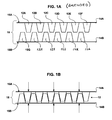
- FIG. 1A is an enlarged cross-sectional view of two microreplicated structures that collectively form a mated fastening structure.
- FIG. 1B is another enlarged cross-sectional view of the mated fastening structure of FIG. 1A, with the two microreplicated structures being forced together into mated engagement.
- FIG. 2 is a perspective view of two microreplicated structures that collectively form a mated fastening structure.
- FIG. 3 is another enlarged cross-sectional view of a microreplicated structure according to an embodiment of the invention.
- FIG. 4 is a cross-sectional view of a microreplication tool according to an embodiment of the invention.
- FIG. 5 is an enlarged cross-sectional view of a microreplication tool according to another embodiment of the invention.
- FIG. 6 is a flow diagram illustrating an exemplary process for the creation and use of a the microreplication tool illustrated in FIG. 5 .
- FIG. 7 is an enlarged cross-sectional view of a master that can be used in creating a microreplication tool.
- FIG. 8 is an enlarged cross-sectional view of the master of FIG. 7 with material electroplated on the mastered surface.
- FIG. 9 is an enlarged cross-sectional view illustrating the electroplated material of FIG. 8 with the master removed.
- FIG. 10 is a perspective view of a microreplication system making use of a microreplication tool in the form of a casting belt according to an embodiment of the invention.
- FIG. 11 is a perspective view of a microreplication system making use of a microreplication tool in the form of a casting roller according to an embodiment of the invention.
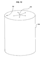
- FIG. 12 is a perspective view of an electroplating apparatus for creating a casting roller according to an embodiment of the invention.
- FIGS. 13A and 13B are cross-sectional diagrams comparing a conventional microreplicated structure to a microreplicated structure created using one or more techniques described herein.
- microreplication tools that include gas release features that allow gas to escape from microreplication cavities of the tool.
- the microreplication tool may comprise an extrusion tool, such as a casting belt or a casting roller, or possibly an injection molding tool used for injection molding structures that define the small microreplicated features.
- incorporating gas release features in the microreplication tool can improve the quality of microreplicated structures created using the tool by reducing air entrapment within the cavities during the microreplication process.
- the incidence of surface irregularities or other air pocket artifacts on the microreplicated structures can be reduced or substantially eliminated.
- FIG. 1A is a cross-sectional view of two microreplicated structures that collectively form a mated fastening structure.
- microreplicated features 12 A- 12 F (collectively features 12 ) in the form of tapered protrusions, extend from a backing structure 14 A to form a first microreplicated structure 15 A.
- microreplicated features 12 G- 12 L (collectively features 12 ) in the form of tapered elements extend from a backing structure 14 B to form a second microreplicated structure 15 B.
- first microreplicated structure 15 A and second microreplicated structure 15 B can be forced together such that the microreplicated features 12 fit together in a friction-fit interlocking arrangement.
- first and second microreplicated structures 15 A and 15 B define a mated surface fastener 18 . Accordingly, back sides of first and second microreplicated structures 15 A and 15 B structures can be affixed to different articles or surfaces so that mated surface fastener 18 serves as a connecting structure.
- first and second microreplicated structures 15 A and 15 B can be created using microreplication tools that include gas release features that allow gas to escape from microreplication cavities of the tool.
- microreplication tools that include gas release features that allow gas to escape from microreplication cavities of the tool.
- the shape of microreplicated features 12 can be more precisely defined by the cavities of the tool, and the incidence of physical artifacts, i.e., irregularities, on features 12 caused by air entrapment within the tool can be reduced or substantially avoided.
- FIG. 2 is a perspective view of mated surface fastener 18 illustrated in FIGS. 1A and 1B.
- features 12 have a four-sided profile.
- the profile may be defined to include any number of sides.
- a circular, oval or elliptical profile may also be defined, if desired.
- mated surface fastener 18 can be used for a wide variety of applications.
- the outer surfaces 19 A and 19 B of sides 15 A and 15 B may be adhered to items so that the items can be removably fastened to one another.
- Mated surface fastener 18 may be particularly useful for clean room applications where adhesives may cause contamination. Medical clean rooms and clean rooms used for electronic circuit construction or assembly are two examples.
- Other applications may include applications for anti-skid surfaces, fasteners for pull-over covers, handle wraps for sports equipment or the like, applications for plasma display panels, and other applications.
- the embodiments outlined below are readily applicable to a wide variety of microreplicated features and microreplicated structures.
- tapered protrusions of microreplicated structures that form a mated surface fastener are just one exemplary embodiment of microreplicated features that can benefit from the invention.
- FIG. 3 is another cross-sectional view of a microreplicated structure according to an embodiment of the invention.
- each microreplicated feature 12 M- 12 R may have a number of dimensions (X, Y and Z).
- the terms microreplication and microreplicated features relate to features (such as features 12 ) that have at least one dimension less than approximately 1000 microns. In other words, at least one of the dimensions X, Y or Z is less than approximately 1000 microns.
- microreplicated features 12 may have a width X on the order of approximately 15-70 microns, a height Y on the order of approximately 45-210 microns, and width Z on the order of 15-70 microns.
- Features 12 may also be characterized as having a high aspect ratio, such as an aspect ratio larger than 3, larger than 5, or larger than 10.
- the height Z may be approximately 3, 5 or 10 times larger than the width X or the width Y.
- features 12 can be more precisely defined by the cavities of the microreplication tool.
- features 12 generally do not exhibit artifacts or surface irregularities caused by air entrapment within cavities of the microreplication tool. The techniques are particularly useful when creating features with high aspect ratios.
- FIG. 4 is an enlarged cross-sectional side view of one embodiment of a portion of microreplication tool 40 .
- microreplication tool 40 may be a casting belt or a casting roller used in an extrusion process, a molding tool used in an injection molding apparatus, or any other microreplication tool.
- microreplication tool 40 includes a microreplication surface 48 formed with a number of cavities 42 A, 42 B, 42 C (collectively referred to as cavities 42 ). Cavities 42 are used to form microreplicated features (such as features 12 ) during a microreplication process. Accordingly, the size and shape of cavities 42 may substantially correspond to the size and shape of features 12 described above, and may also vary according to any desired shape of microreplicated features. As illustrated in FIG.
- microreplication tool 40 includes gas release features disposed adjacent bottom regions of the respective cavities 42 to allow gas to escape from the cavities during the microreplication process.
- the gas release features comprise a layer of porous material 45 that defines the bottom of cavities 42 .
- a porous material 45 can be provided, such as in the form of a substrate.
- the porous material 45 can be masked, such as by using electroforming masking techniques.
- Material 46 can then be electroformed on the porous material 45 .
- the masking of porous material 45 can define the microreplication pattern of cavities defined by electroformed material 46 after the electroforming process.
- a deposition process may precede the electroforming process to form a thin layer of material that serves as a seed layer to the electroformed material.
- Material can be electroformed to an extent sufficient to define widths and depths of the cavities used for creating features 12 described above.
- porous material 45 forms the bottoms of cavities 42 , gas can escape through the porous material 45 when the microreplication tool is used.
- microreplication tool 40 can be more completely filled with deposited material because air is not trapped in cavities 42 .
- FIG. 5 is an enlarged cross-section side view of another embodiment of a portion of a microreplication tool 50 .
- microreplication tool 50 may be a casting belt or a casting roller used in an extrusion process, a molding tool used in an injection molding apparatus, or any other microreplication tool.
- microreplication tool 50 includes a microreplication surface 58 formed with a number of cavities 52 A, 52 B, 52 C (collectively referred to as cavities 52 ). Cavities 52 are used to form microreplicated features (such as features 12 ) during a microreplication process.
- the size and shape of cavities 52 may substantially correspond to the size and shape of features 12 described above. As illustrated in FIG.
- microreplication tool 50 includes gas release features disposed adjacent bottom regions of the respective cavities 52 to allow gas to escape from the cavities during the microreplication process.
- the gas release features comprise channels 53 A, 53 B and 53 C (collectively channels 53 ) formed at the bottoms of cavities 52 .
- channels 53 may be sized so that that air or other gasses can escape, while the material being microreplicated cannot escape.
- cavities 52 of microreplication tool 50 can be more completely filled because air is not trapped in cavities 52 .
- air or other gasses can escape through channels 53 so that cavities 52 can be more completely filled with material.
- features of microreplicated structures can be improved by avoiding surface irregularities or artifacts associated with air entrapment within cavities 52 .
- channels 53 may be defined so that the material being used to fill cavities 52 cannot pass through the channels, but trapped gasses can escape.
- the cross-sectional width of channels 53 (defined perpendicular to a direction that air flows through channels 53 ) may be as small as approximately 20 microns, approximately 10 microns, approximately 1 micron or even approximately 0.1 microns at the smallest diameter point.
- the optimal width of channels 53 may be selected based on the material composition used to create the final microreplicated product.
- FIG. 6 is a flow diagram illustrating the creation and use of a the microreplication tool illustrated in FIG. 5 .
- the creation process for microreplication tool 50 may begin with a mastering process.
- a master is created ( 61 ) to define mastered features that are the inverse of a set of cavities to be created in the microreplication tool.
- the mastered features can be formed to include pyramid-like protrusions at the ends of the mastered features.
- FIG. 7 is an enlarged cross-sectional side view of an exemplary master 70 that includes mastered features 72 A, 72 B and 72 C (collectively mastered features 72 ) formed to include pyramid-like shaped protrusions 74 A, 74 B and 74 C (collectively pyramid-like shaped protrusions 74 ) at the ends of the mastered features 72 .
- Mastered features 72 may be the inverse of the cavities 52 to be created in microreplication tool 50 (FIG. 5 ). Similarly, pyramid-like protrusions 74 may be the inverse of the channels 53 to be created in microreplication tool 50 .
- the mastering process may involve one or more of a wide variety of known mastering techniques. For example, diamond turning techniques, laser machining techniques, conventional machining techniques such as carbide milling, electro-discharge machining (EDM) techniques, reactive ion etching techniques, additive processes such as stereo lithography, or the like, may be used to create master 70 ( 61 ). Mastered features 72 may ultimately define the size and shape of features being created (such as features 12 shown in FIGS. 1 - 3 ).
- FIG. 8 illustrates a structure that includes master 70 with material 80 electroformed on the master surface.
- the electroformed material 80 may completely cover mastered features 72 as well as pyramid-like shaped protrusions 74 .
- Electroforming techniques are well know techniques for forming a relatively thick layer of material on a master surface. For example, a thin layer of material may be originally deposited on the master surface, before placing the coated master surface in an electroforming process solution. Electroforming techniques can then be used to uniformly form material 80 on the master surface.
- the electroformed material 80 may comprise a metal, such as nickel, copper, or the like, and the metal can be uniformly built up to the desired thickness, such as a thickness sufficient to completely cover mastered features 72 and pyramid-like protrusions 74 .
- FIG. 9 shows the electroformed structure 90 after the master has been removed.
- the master may be removed by physically separating the master 70 from electroformed material 80 (FIG. 8 ). Any excess mastered material that remains in the cavities 92 or channels 93 may be removed by a stripper chemical, or the like.
- a portion of the electroformed material can be removed ( 64 ) to expose channels 53 (FIG. 5) defined by the pyramid-like protrusions 74 (FIG. 8 ).
- the portion 95 of the electroplated structure 90 can be removed, such as by etching or abating the material away.
- the microreplication tool illustrated in FIG. 5 can be created.
- channels 53 can be exposed by removing material 95 (FIG. 9) such that gas can escape from cavities 52 through channels 53 (FIG. 5 ).
- material 95 may be removed to an extent sufficient to expose channels 93 by a dimension less than approximately 20 microns, 10 microns, 1 micron, or even 0.1 micron.
- an aperture defined by exposed channels following the removal of material 95 may have an aperture width less than approximately 20 microns, 10 microns, 1 micron, or even 0.1 micron.
- the tool After removing the excess electroformed material to expose the channels in the tool ( 64 ), the tool can be used in a microreplication process ( 65 ). In that case, during the microreplication process, microreplication material may completely fill cavities 52 because gasses, such as air, can escape through channels 53 (FIG. 5 ).
- a number of segmented electroformed structures can be positioned over a larger surface to define a larger microreplication tool.
- the process illustrated in FIG. 6 may be repeated to create a number of segments of a molding tool that can be positioned or assembled according to the shape of the molding tool.
- the surface of the tool may be textured or roughened.
- surface 48 of microreplication tool 40 , or surface 58 of microreplication tool 50 may be textured, such as by sandblasting the surface after creating the tool. Texturing the side-walls and/or the bottoms of the cavities may be particularly useful to improve filling of the cavities.
- FIG. 10 is a perspective view of a microreplication system 100 making use of a microreplication tool in the form of a casting belt 102 according to an embodiment.
- material can be extruded by passing the material between casting belt 102 and a roller 104 .
- the casting belt 102 may comprise a number of segmented electroformed structures that include cavities with channels disposed at the bottoms of the respective cavities to allow gas to escape from the cavities during the microreplication process.
- casting belt 102 may be assembled from a number of segmented electroformed structures created as described above.
- FIG. 11 is another perspective view of a microreplication system 110 making use of a microreplication tool in the form of a casting roller 112 .
- material can be extruded by passing the material between casting roller 112 and a conveyor 114 . Additional nip rollers may also be provided on the back side of conveyor 114 .
- FIG. 12 is a perspective view of an electroplating apparatus for creating a casting roller like that illustrated in FIG. 11 .
- the master may be positioned on an inner surface 122 of cylindrical electroforming chamber 124 .
- the electroforming process may cause the electroforming material to form on the master surface provided on inner surface 122 of cylindrical electroforming chamber 124 (as illustrated by arrows 126 ).
- Such electroforming techniques can be used to create a casting roller like that illustrated in FIG. 11 .
- the microreplication tool can be enhanced as outlined above.
- FIGS. 13A and 13B are cross-sectional diagrams comparing a conventional microreplicated structure with a microreplicated structure created using one or more techniques described herein.
- FIG. 13A illustrates a conventional microreplicated structure.
- FIG. 13A may be slightly exaggerated for illustrated purposes.
- conventional microreplicated structures generally exhibit artifacts in the form of surface irregularities 131 .
- surface irregularities 131 are caused by air entrapment in the microreplication tool.
- surface irregularities 131 may be generally exhibited on the top surfaces of the microreplicated features.
- surface irregularities 131 can be reduced or substantially eliminated as conceptually shown in FIG. 13B by utilizing microreplication tools that include gas release features disposed at the bottoms of the respective cavities to allow gas to escape from the cavities during the microreplication process. In this manner, improved microreplicated structures, like that illustrated in FIG. 13B can be realized.
- microreplication tool that includes gas release features that allows air or other gasses to escape from microreplication cavities of the tool has been described.
- the microreplication tool may be a tool other than a casting belt, a casting roller, or an injection molding tool.
- the techniques and microreplication tools described herein may be created according to any desired microreplication features.
- one or more of the structural devices and techniques may be extended for application in larger scale replication tools, such as tools used for replicating structures with larger features than those described herein. Accordingly, other implementations and embodiments are within the scope of the following claims.
Landscapes
- Engineering & Computer Science (AREA)
- Mechanical Engineering (AREA)
- Chemical & Material Sciences (AREA)
- Chemical Kinetics & Catalysis (AREA)
- Electrochemistry (AREA)
- Materials Engineering (AREA)
- Metallurgy (AREA)
- Organic Chemistry (AREA)
- Manufacturing & Machinery (AREA)
- Moulds For Moulding Plastics Or The Like (AREA)
Priority Applications (8)
| Application Number | Priority Date | Filing Date | Title |
|---|---|---|---|
| US10/160,744 US6824378B2 (en) | 2002-05-31 | 2002-05-31 | Microreplication tool with gas release features |
| AU2003234308A AU2003234308A1 (en) | 2002-05-31 | 2003-05-01 | Microreplication tool with gas release features |
| JP2004509028A JP4567444B2 (ja) | 2002-05-31 | 2003-05-01 | 気体放出造作体を備えた微細複製工具 |
| EP03728622A EP1511609A1 (en) | 2002-05-31 | 2003-05-01 | Microreplication tool with gas release features |
| CNB038175266A CN100415475C (zh) | 2002-05-31 | 2003-05-01 | 具有放气特征的微复制工具 |
| PCT/US2003/013461 WO2003101698A1 (en) | 2002-05-31 | 2003-05-01 | Microreplication tool with gas release features |
| KR1020047019315A KR100955970B1 (ko) | 2002-05-31 | 2003-05-01 | 가스 해제 형상부를 갖춘 미세 복제 공구 |
| BR0311424-4A BR0311424A (pt) | 2002-05-31 | 2003-05-01 | Ferramenta de micro-replicação, método para criar a mesma, estrutura micro-replicada, e, sistema de micro-replicação |
Applications Claiming Priority (1)
| Application Number | Priority Date | Filing Date | Title |
|---|---|---|---|
| US10/160,744 US6824378B2 (en) | 2002-05-31 | 2002-05-31 | Microreplication tool with gas release features |
Publications (2)
| Publication Number | Publication Date |
|---|---|
| US20030224144A1 US20030224144A1 (en) | 2003-12-04 |
| US6824378B2 true US6824378B2 (en) | 2004-11-30 |
Family
ID=29583251
Family Applications (1)
| Application Number | Title | Priority Date | Filing Date |
|---|---|---|---|
| US10/160,744 Expired - Fee Related US6824378B2 (en) | 2002-05-31 | 2002-05-31 | Microreplication tool with gas release features |
Country Status (8)
| Country | Link |
|---|---|
| US (1) | US6824378B2 (enExample) |
| EP (1) | EP1511609A1 (enExample) |
| JP (1) | JP4567444B2 (enExample) |
| KR (1) | KR100955970B1 (enExample) |
| CN (1) | CN100415475C (enExample) |
| AU (1) | AU2003234308A1 (enExample) |
| BR (1) | BR0311424A (enExample) |
| WO (1) | WO2003101698A1 (enExample) |
Cited By (11)
| Publication number | Priority date | Publication date | Assignee | Title |
|---|---|---|---|---|
| US20070014997A1 (en) * | 2005-07-14 | 2007-01-18 | 3M Innovative Properties Company | Tool and method of making and using the same |
| US20070013103A1 (en) * | 2005-07-14 | 2007-01-18 | 3M Innovative Properties Company | Nanostructured article and method of making the same |
| US20070015288A1 (en) * | 2005-07-14 | 2007-01-18 | 3M Innovative Properties Company | Surface-enhanced spectroscopic method, flexible structured substrate, and method of making the same |
| US20080248203A1 (en) * | 2005-04-22 | 2008-10-09 | Eliason Kevin M | Masking Article and Method of Masking of Substrate |
| US20130313339A1 (en) * | 2011-02-02 | 2013-11-28 | 3M Innovative Properties Company | Nozzle and method of making same |
| US20160303594A1 (en) * | 2013-12-05 | 2016-10-20 | 3M Innovative Properties Company | Container for a spraying device |
| US10099043B2 (en) | 2013-07-16 | 2018-10-16 | 3M Innovative Properties Company | Hollow microneedle array article |
| US10201691B2 (en) | 2013-07-16 | 2019-02-12 | 3M Innovative Properties | Article comprising a microneedle |
| US10232157B2 (en) | 2013-07-16 | 2019-03-19 | 3M Innovative Properties Company | Hollow microneedle with beveled tip |
| US10384047B2 (en) | 2013-07-16 | 2019-08-20 | 3M Innovative Properties Company | Hollow microneedle with bevel opening |
| RU2702550C2 (ru) * | 2015-04-15 | 2019-10-08 | Авери Деннисон Корпорейшн | Вентилируемый обрабатывающий ремень для изготовления структурированных поверхностей |
Families Citing this family (18)
| Publication number | Priority date | Publication date | Assignee | Title |
|---|---|---|---|---|
| JP4599086B2 (ja) * | 2004-04-23 | 2010-12-15 | 株式会社リコー | 成形用金型 |
| FR2869601B1 (fr) * | 2004-04-28 | 2006-06-09 | Commissariat Energie Atomique | Moule pour la nano-impression, procede de fabrication d'un tel moule et utilisation d'un tel moule |
| US7418202B2 (en) | 2005-08-04 | 2008-08-26 | 3M Innovative Properties Company | Article having a birefringent surface and microstructured features having a variable pitch or angles for use as a blur filter |
| JP4872052B2 (ja) * | 2006-04-12 | 2012-02-08 | 独立行政法人産業技術総合研究所 | 微細金型コア部材 |
| US9134471B2 (en) | 2006-06-28 | 2015-09-15 | 3M Innovative Properties Company | Oriented polymeric articles and method |
| FR2918677A1 (fr) * | 2007-07-13 | 2009-01-16 | Aplix Sa | Installation de fabrication de nappes a tiges pouvant etre obtenue par cette installation |
| KR101610180B1 (ko) | 2007-11-21 | 2016-04-07 | 캐논 나노테크놀로지즈 인코퍼레이티드 | 나노-임프린트 리소그래피용 다공성 주형 및 임프린팅 스택 |
| US20100104852A1 (en) * | 2008-10-23 | 2010-04-29 | Molecular Imprints, Inc. | Fabrication of High-Throughput Nano-Imprint Lithography Templates |
| US20100109201A1 (en) * | 2008-10-31 | 2010-05-06 | Molecular Imprints, Inc. | Nano-Imprint Lithography Template with Ordered Pore Structure |
| NL2003600A (en) * | 2008-12-04 | 2010-06-07 | Asml Netherlands Bv | Imprint lithography apparatus and method. |
| US20110148008A1 (en) * | 2009-12-23 | 2011-06-23 | National Cheng Kung University | Micro-nano imprint mould and imprinting process |
| US8875356B2 (en) | 2011-10-06 | 2014-11-04 | Intercontinental Great Brands Llc | Mechanical and adhesive based reclosable fasteners |
| JP2016510375A (ja) * | 2012-12-21 | 2016-04-07 | スリーエム イノベイティブ プロパティズ カンパニー | 射出成形工程を含む、ノズルを製造する方法 |
| CN107848073B (zh) * | 2015-06-10 | 2019-04-19 | 沙特基础工业全球技术有限公司 | 在固体塑料零件上形成表面结构的方法和包含由该方法形成的固体塑料零件的照明产品 |
| JP6734652B2 (ja) * | 2016-01-15 | 2020-08-05 | 株式会社ブリヂストン | ゴム物品用モールドの製造方法 |
| DE202016101299U1 (de) * | 2016-03-09 | 2017-06-12 | Kuka Systems Gmbh | Matrize |
| CN106378906B (zh) * | 2016-11-08 | 2018-06-22 | 浙江大学宁波理工学院 | 注塑模具 |
| US20250334856A1 (en) * | 2024-04-25 | 2025-10-30 | Tesla, Inc. | Cone-textured glare shield for enhanced camera vision |
Citations (14)
| Publication number | Priority date | Publication date | Assignee | Title |
|---|---|---|---|---|
| US86660A (en) | 1869-02-09 | Improvement in lamp-chimneys | ||
| US3399425A (en) | 1966-08-23 | 1968-09-03 | Jerome H. Lemelson | Apparatus for surface forming materials |
| US3822857A (en) * | 1971-02-16 | 1974-07-09 | Toyo Tire & Rubber Co | Synthetic resin plug for vent hole of mould |
| US4208368A (en) | 1978-07-18 | 1980-06-17 | Gebruder Buhler Ag | Method and apparatus for injection molding foamed plastic articles using a pre-pressurized mold having fixed core members with controlled venting |
| JPS5847538A (ja) | 1981-09-14 | 1983-03-19 | Alps Electric Co Ltd | 金型 |
| US4846938A (en) | 1987-07-13 | 1989-07-11 | Honda Giken Kogyo Kabushiki Kaisha | Method of manufacturing a porous electroformed object |
| US5077870A (en) | 1990-09-21 | 1992-01-07 | Minnesota Mining And Manufacturing Company | Mushroom-type hook strip for a mechanical fastener |
| JPH0780848A (ja) * | 1993-09-09 | 1995-03-28 | Bridgestone Sports Co Ltd | ゴルフボール用金型及びゴルフボール |
| EP0771537A2 (en) | 1995-11-06 | 1997-05-07 | Ykk Corporation | Molded surface fastener, and method and apparatus for manufacturing the same |
| US5688193A (en) * | 1995-07-17 | 1997-11-18 | Bridgestone Sports Co., Ltd. | Golf ball and mold therefor |
| US5845375A (en) | 1990-09-21 | 1998-12-08 | Minnesota Mining And Manufacturing Company | Mushroom-type hook strip for a mechanical fastener |
| US6223401B1 (en) | 1998-10-01 | 2001-05-01 | 3M Innovative Properties Company | Intermeshable articles |
| US20020035854A1 (en) * | 2000-07-15 | 2002-03-28 | Herzbach Lars Christian | Method for making a microstructure in a glass or plastic substrate according to hot-forming technology and associated forming tool |
| US20030102591A1 (en) * | 2000-06-16 | 2003-06-05 | Avery Dennison Corporation Delaware | Process and apparatus for embossing precise microstructures and embossing tool for making same |
Family Cites Families (4)
| Publication number | Priority date | Publication date | Assignee | Title |
|---|---|---|---|---|
| JPS6220811U (enExample) * | 1985-07-24 | 1987-02-07 | ||
| GB8703972D0 (en) * | 1987-02-20 | 1987-03-25 | Bicc Plc | Electrical adaptor |
| JP3100337B2 (ja) * | 1996-01-09 | 2000-10-16 | 江南特殊産業株式会社 | 多孔質電鋳殻及びその製造方法 |
| US6682332B2 (en) | 2001-08-14 | 2004-01-27 | Alcoa Inc. | Dual isolated mode controller for injection molding machine |
-
2002
- 2002-05-31 US US10/160,744 patent/US6824378B2/en not_active Expired - Fee Related
-
2003
- 2003-05-01 JP JP2004509028A patent/JP4567444B2/ja not_active Expired - Fee Related
- 2003-05-01 CN CNB038175266A patent/CN100415475C/zh not_active Expired - Fee Related
- 2003-05-01 AU AU2003234308A patent/AU2003234308A1/en not_active Abandoned
- 2003-05-01 KR KR1020047019315A patent/KR100955970B1/ko not_active Expired - Fee Related
- 2003-05-01 WO PCT/US2003/013461 patent/WO2003101698A1/en not_active Ceased
- 2003-05-01 EP EP03728622A patent/EP1511609A1/en not_active Withdrawn
- 2003-05-01 BR BR0311424-4A patent/BR0311424A/pt not_active IP Right Cessation
Patent Citations (14)
| Publication number | Priority date | Publication date | Assignee | Title |
|---|---|---|---|---|
| US86660A (en) | 1869-02-09 | Improvement in lamp-chimneys | ||
| US3399425A (en) | 1966-08-23 | 1968-09-03 | Jerome H. Lemelson | Apparatus for surface forming materials |
| US3822857A (en) * | 1971-02-16 | 1974-07-09 | Toyo Tire & Rubber Co | Synthetic resin plug for vent hole of mould |
| US4208368A (en) | 1978-07-18 | 1980-06-17 | Gebruder Buhler Ag | Method and apparatus for injection molding foamed plastic articles using a pre-pressurized mold having fixed core members with controlled venting |
| JPS5847538A (ja) | 1981-09-14 | 1983-03-19 | Alps Electric Co Ltd | 金型 |
| US4846938A (en) | 1987-07-13 | 1989-07-11 | Honda Giken Kogyo Kabushiki Kaisha | Method of manufacturing a porous electroformed object |
| US5077870A (en) | 1990-09-21 | 1992-01-07 | Minnesota Mining And Manufacturing Company | Mushroom-type hook strip for a mechanical fastener |
| US5845375A (en) | 1990-09-21 | 1998-12-08 | Minnesota Mining And Manufacturing Company | Mushroom-type hook strip for a mechanical fastener |
| JPH0780848A (ja) * | 1993-09-09 | 1995-03-28 | Bridgestone Sports Co Ltd | ゴルフボール用金型及びゴルフボール |
| US5688193A (en) * | 1995-07-17 | 1997-11-18 | Bridgestone Sports Co., Ltd. | Golf ball and mold therefor |
| EP0771537A2 (en) | 1995-11-06 | 1997-05-07 | Ykk Corporation | Molded surface fastener, and method and apparatus for manufacturing the same |
| US6223401B1 (en) | 1998-10-01 | 2001-05-01 | 3M Innovative Properties Company | Intermeshable articles |
| US20030102591A1 (en) * | 2000-06-16 | 2003-06-05 | Avery Dennison Corporation Delaware | Process and apparatus for embossing precise microstructures and embossing tool for making same |
| US20020035854A1 (en) * | 2000-07-15 | 2002-03-28 | Herzbach Lars Christian | Method for making a microstructure in a glass or plastic substrate according to hot-forming technology and associated forming tool |
Non-Patent Citations (3)
| Title |
|---|
| Bowen, R.: "Proper Utilization of Porous Mold Steel to Solve Venting Problems" ANTEC 1999-Annual Technical Conference of the Society of Plastics Engineers, vol. 1, May 1999, XP002252597. |
| Menges, G; Michaeli, W.; Mohren, P., How to Make Injection Molds 2000, Hanser, Munich XP002252598. |
| Weber et al, Mikroabformung, Verfahren, Werkzeuge, Anwendungen, Micro-Moulding-Processes, Moulds, Applications, Kunststoffe, Carl Hanswer Verlag, Munchen, DE, vol. 88, 1998 pp. 1791-1792, 1794, 1796, 1798, 1800, 1802, XP000981365 (translation attached). |
Cited By (22)
| Publication number | Priority date | Publication date | Assignee | Title |
|---|---|---|---|---|
| US20080248203A1 (en) * | 2005-04-22 | 2008-10-09 | Eliason Kevin M | Masking Article and Method of Masking of Substrate |
| US8399058B2 (en) * | 2005-04-22 | 2013-03-19 | 3M Innovative Properties Company | Masking article and method of masking of substrate |
| US20070014997A1 (en) * | 2005-07-14 | 2007-01-18 | 3M Innovative Properties Company | Tool and method of making and using the same |
| US20070013103A1 (en) * | 2005-07-14 | 2007-01-18 | 3M Innovative Properties Company | Nanostructured article and method of making the same |
| US20070015288A1 (en) * | 2005-07-14 | 2007-01-18 | 3M Innovative Properties Company | Surface-enhanced spectroscopic method, flexible structured substrate, and method of making the same |
| US7651863B2 (en) | 2005-07-14 | 2010-01-26 | 3M Innovative Properties Company | Surface-enhanced spectroscopic method, flexible structured substrate, and method of making the same |
| US7888129B2 (en) | 2005-07-14 | 2011-02-15 | 3M Innovative Properties Company | Surface-enhanced spectroscopic method, flexible structured substrate, and method of making the same |
| US7906057B2 (en) | 2005-07-14 | 2011-03-15 | 3M Innovative Properties Company | Nanostructured article and method of making the same |
| US10054094B2 (en) * | 2011-02-02 | 2018-08-21 | 3M Innovative Properties Company | Microstructured pattern for forming a nozzle pre-form |
| US20130313339A1 (en) * | 2011-02-02 | 2013-11-28 | 3M Innovative Properties Company | Nozzle and method of making same |
| US10576257B2 (en) | 2013-07-16 | 2020-03-03 | 3M Innovative Properties Company | Article comprising a microneedle and methods of use |
| US10099043B2 (en) | 2013-07-16 | 2018-10-16 | 3M Innovative Properties Company | Hollow microneedle array article |
| US10201691B2 (en) | 2013-07-16 | 2019-02-12 | 3M Innovative Properties | Article comprising a microneedle |
| US10232157B2 (en) | 2013-07-16 | 2019-03-19 | 3M Innovative Properties Company | Hollow microneedle with beveled tip |
| US10384047B2 (en) | 2013-07-16 | 2019-08-20 | 3M Innovative Properties Company | Hollow microneedle with bevel opening |
| US11541407B2 (en) * | 2013-12-05 | 2023-01-03 | 3M Innovative Properties Company | Container for a spraying device |
| US10857553B2 (en) * | 2013-12-05 | 2020-12-08 | 3M Innovative Properties Company | Container for a spraying device |
| US20160303594A1 (en) * | 2013-12-05 | 2016-10-20 | 3M Innovative Properties Company | Container for a spraying device |
| US20230096717A1 (en) * | 2013-12-05 | 2023-03-30 | 3M Innovative Properties Company | Container for a spraying device |
| US11958069B2 (en) * | 2013-12-05 | 2024-04-16 | 3M Innovative Properties Company | Container for a spraying device |
| US20240216934A1 (en) * | 2013-12-05 | 2024-07-04 | 3M Innovative Properties Company | Container for a spraying device |
| RU2702550C2 (ru) * | 2015-04-15 | 2019-10-08 | Авери Деннисон Корпорейшн | Вентилируемый обрабатывающий ремень для изготовления структурированных поверхностей |
Also Published As
| Publication number | Publication date |
|---|---|
| WO2003101698A1 (en) | 2003-12-11 |
| CN1671530A (zh) | 2005-09-21 |
| KR100955970B1 (ko) | 2010-05-04 |
| JP2005528255A (ja) | 2005-09-22 |
| AU2003234308A1 (en) | 2003-12-19 |
| KR20050016469A (ko) | 2005-02-21 |
| US20030224144A1 (en) | 2003-12-04 |
| JP4567444B2 (ja) | 2010-10-20 |
| EP1511609A1 (en) | 2005-03-09 |
| BR0311424A (pt) | 2005-03-15 |
| CN100415475C (zh) | 2008-09-03 |
Similar Documents
| Publication | Publication Date | Title |
|---|---|---|
| US6824378B2 (en) | Microreplication tool with gas release features | |
| EP0328278B1 (en) | Apparatus and methods for using a plating mask | |
| KR101919429B1 (ko) | 수명이 연장된 텍스쳐링된 챔버 부품들 및 그 제조 방법 | |
| US6099289A (en) | Forming mold cavities | |
| US8398390B2 (en) | Die for forming honeycomb structure | |
| US20060157381A1 (en) | Component carrier and method for making | |
| US20090061040A1 (en) | Die for forming honeycomb structure | |
| KR20220082933A (ko) | 증착물 보유력을 증가시키기 위한 표면 텍스처링을 위한 기하형상들 및 패턴들 | |
| WO2008048785A1 (en) | Component carrier and method for making | |
| EP0143555A1 (en) | A die for extruding honeycomb structural body and a method of manufacturing the same | |
| EP1017553B1 (en) | Forming mold cavities | |
| EP0876247A1 (en) | Stacked laminate mold and method of making | |
| US12005605B2 (en) | Method of modifying a honeycomb-structure-forming extrusion die and modified extrusion dies | |
| US6939123B2 (en) | Electroformed adhesive laminated tooling surface with precision structured interfaces | |
| CN108687656B (zh) | 工件游星轮及工件游星轮的制造方法 | |
| JP2010280217A (ja) | ハニカム押出ダイ装置および方法 | |
| US5660638A (en) | Jig for producing electronic components with side electrodes | |
| JP2005019834A (ja) | キャリアプレート | |
| US6305924B1 (en) | Stacked laminate mold | |
| EP1871925B1 (en) | Method for electroforming a studded plate | |
| KR20090046811A (ko) | 복합형 표면의 미세복제 | |
| TW202120328A (zh) | 孔洞結構及其製作方法以及包含孔洞結構之異材質接合結構及其製作方法 | |
| TWI715590B (zh) | 組件載帶及其製造方法 | |
| EP1568657A3 (en) | Method of manufacturing nanostructure arrays |
Legal Events
| Date | Code | Title | Description |
|---|---|---|---|
| AS | Assignment |
Owner name: 3M INNOVATIVE PROPERTIES COMPANY, MINNESOTA Free format text: ASSIGNMENT OF ASSIGNORS INTEREST;ASSIGNORS:KING, VINCENT W.;D'SA, JOSEPH M.;FEHR, ROBERT T.;AND OTHERS;REEL/FRAME:013297/0940;SIGNING DATES FROM 20020810 TO 20020830 |
|
| FPAY | Fee payment |
Year of fee payment: 4 |
|
| FPAY | Fee payment |
Year of fee payment: 8 |
|
| REMI | Maintenance fee reminder mailed | ||
| LAPS | Lapse for failure to pay maintenance fees | ||
| STCH | Information on status: patent discontinuation |
Free format text: PATENT EXPIRED DUE TO NONPAYMENT OF MAINTENANCE FEES UNDER 37 CFR 1.362 |
|
| FP | Lapsed due to failure to pay maintenance fee |
Effective date: 20161130 |